EP1167159A1 - Servo valve for hydraulic power steering of a motor vehicle - Google Patents
Servo valve for hydraulic power steering of a motor vehicle Download PDFInfo
- Publication number
- EP1167159A1 EP1167159A1 EP01420121A EP01420121A EP1167159A1 EP 1167159 A1 EP1167159 A1 EP 1167159A1 EP 01420121 A EP01420121 A EP 01420121A EP 01420121 A EP01420121 A EP 01420121A EP 1167159 A1 EP1167159 A1 EP 1167159A1
- Authority
- EP
- European Patent Office
- Prior art keywords
- assistance
- oil
- hydraulic
- valve
- dead
- Prior art date
- Legal status (The legal status is an assumption and is not a legal conclusion. Google has not performed a legal analysis and makes no representation as to the accuracy of the status listed.)
- Granted
Links
Images

Classifications
-
- B—PERFORMING OPERATIONS; TRANSPORTING
- B62—LAND VEHICLES FOR TRAVELLING OTHERWISE THAN ON RAILS
- B62D—MOTOR VEHICLES; TRAILERS
- B62D5/00—Power-assisted or power-driven steering
- B62D5/06—Power-assisted or power-driven steering fluid, i.e. using a pressurised fluid for most or all the force required for steering a vehicle
- B62D5/08—Power-assisted or power-driven steering fluid, i.e. using a pressurised fluid for most or all the force required for steering a vehicle characterised by type of steering valve used
- B62D5/083—Rotary valves
-
- F—MECHANICAL ENGINEERING; LIGHTING; HEATING; WEAPONS; BLASTING
- F16—ENGINEERING ELEMENTS AND UNITS; GENERAL MEASURES FOR PRODUCING AND MAINTAINING EFFECTIVE FUNCTIONING OF MACHINES OR INSTALLATIONS; THERMAL INSULATION IN GENERAL
- F16K—VALVES; TAPS; COCKS; ACTUATING-FLOATS; DEVICES FOR VENTING OR AERATING
- F16K47/00—Means in valves for absorbing fluid energy
- F16K47/02—Means in valves for absorbing fluid energy for preventing water-hammer or noise
Definitions
- the present invention relates to steering systems hydraulic assisted, for motor vehicles. More specifically, this invention relates to an improvement made to the valves assistance, usually incorporated in this type of directions assisted.
- a hydraulic vehicle power steering valve automobile comprises, in a generally known manner, a rotor linked by via a torsion bar to a pinion, itself engaging with the steering rack, the generally tubular rotor being mounted around the torsion bar, and being surrounded by a jacket rotary, linked in rotation with the pinion, the rotor and the pinion being mounted rotating along the same axis in a casing by means of bearings.
- the assistance valve still has filled channels and chambers oil, which allow it to behave like a distributor hydraulic supplying an oil pressure which is an increasing function of the torque applied to this valve and deforming its torsion bar.
- a power steering valve hydraulic contains "dead volumes” filled with oil, volumes in which hydraulic waves can either amortize, or on the contrary enter into resonance, this depending on many parameters that make the generating wave agree or not.
- the present invention aims to improve a valve assistance of the kind considered here, so as to suppress noise and vibrations in question, of hydraulic origin, and the resulting discomfort, by a simple and effective technical solution.
- the invention essentially relates to a valve assistance for hydraulic power steering of a motor vehicle, genre here concerned, which is provided with means for adjusting the volumes dead oil contained in this assistance valve, so as to dampen disturbing hydraulic waves.
- the resonance of the waves depending on the characteristics of dead oil volumes included in the valve is to make the dead volume adjustable oil especially during manufacturing, in order to obtain the amortization of disturbing hydraulic waves.
- This solution allows you to adjust the dead oil volume depending on the specifics of the generating wave and each vehicle, in order to amortize it in an appropriate and certain way, therefore prevent resonance and thereby remove the very cause of noise and vibration phenomena to be avoided.
- the means for adjusting the dead oil volumes are constituted by a screw adjustment, mounted in a tapped hole which is formed in the housing, between a dead volume and the outside. So the dead volume is changed to screwing the adjusting screw more or less deeply into the tapped hole corresponding, this screw being operable from the outside of the valve.
- the means for adjusting the dead oil volumes are supplemented by at least one damping element, such as spring and / or block damper and / or trapped air volume and / or element allowing passage of oil through a restriction orifice, in order to have more latitude to dampen disturbing waves.
- damping element such as spring and / or block damper and / or trapped air volume and / or element allowing passage of oil through a restriction orifice, in order to have more latitude to dampen disturbing waves.
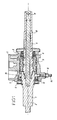
- the assistance valve shown in the drawing comprises, arranged along its longitudinal axis 1 inside the steering casing 2, a pinion 3 and a rotor 4, the latter being partially surrounded by a shirt 5.
- the pinion 3, engaging the rack (not shown), is guided in rotation in the casing 2 by a bearing 6, to which is associated an annular seal 7.
- the rotor 4 is guided in rotation in the casing 2 by another bearing 8, which is also associated with a sealing ring 9.
- the inner end of the pinion 3 is linked in rotation by a drive pin (not shown), in shirt 5.
- the rotor 4 of tubular conformation is linked in rotation by its external part with the steering column of the vehicle concerned.
- a torsion bar 10 AT the inside of the rotor 4, along the axis 1, is arranged a torsion bar 10, one end of which is embedded in the pinion 3, and the other of which end is linked in rotation, by a pin 11, with the end rotor exterior 4.
- the 3-sleeve pinion assembly 5 can describe a relative rotation of limited amplitude, relative to the rotor 4.
- the assistance valve still has chambers and channels hydraulic, allowing it to function as a distributor hydraulic proportional to the torque.
- a resistant torque on the pinion 3 coming from the grip of the wheels steering of the vehicle and transmitted by the rack, and on the other hand, a input torque on the rotor 4 from the flywheel; these two couples are of opposite meanings.
- the hydraulic circuit of such an assistance valve contains "Dead volumes” filled with oil, for example at low pressure, such as annular volume indicated at 12, delimited by the casing 2, the pinion 3, a end of the jacket 5 and the annular seal 7.
- the present invention aims to perfect this kind of valve, so as to suppress noise and vibrations of hydraulic origin, resulting from the resonance of waves hydraulics in dead volumes such as volume 12.
- a hole 13, tapped on at least part of its length is drilled through the casing 2, between a point dead volume 12 and the outside of the assistance valve.
- Tapping hole 13 receives an adjustment screw 14, which can be inserted more or less deeply by screwing in this hole 13, so as to adjust the volume dead 12.
- the adjusting screw 14 receives, externally, a locking nut 15 which is clamped against the outer wall of the casing 2, once the adjustment carried out, so as to immobilize the adjusting screw 14 in the position chosen. There is a seal between the nut 15 and the casing 2.
- Figure 2 shows another embodiment, which includes also an adjustment screw 14, with locking nut 15, screwed into a threaded hole 13 drilled between the dead volume 12 and the outside of the valve assistance.
- the device is here supplemented by a damping element, constituted by a spring 16 associated with a small piston 17, placed in the hole 13 under the adjusting screw 14, in a smooth portion of this hole 13, the piston 17 thus forming a wall portion of the dead volume 12.
- the position and / or the inclination of the tapped hole 13 receiving the adjusting screw 14 can vary, the axis of the hole 13 and of the screw 14 may be perpendicular or oblique to the longitudinal axis 1 of the assistance valve.
Abstract
Description
La présente invention concerne les systèmes de direction assistée hydraulique, pour véhicules automobiles. Plus particulièrement, cette invention a pour objet un perfectionnement apporté aux valves d'assistance, habituellement incorporées dans ce type de directions assistées.The present invention relates to steering systems hydraulic assisted, for motor vehicles. More specifically, this invention relates to an improvement made to the valves assistance, usually incorporated in this type of directions assisted.
Une valve de direction assistée hydraulique de véhicule automobile comprend, de façon généralement connue, un rotor lié par l'intermédiaire d'une barre de torsion à un pignon, venant lui-même en prise avec la crémaillère de la direction, le rotor de forme générale tubulaire étant monté autour de la barre de torsion, et étant entouré par une chemise rotative, liée en rotation avec le pignon, le rotor et le pignon étant montés rotatifs suivant un même axe dans un carter par l'intermédiaire de paliers. La valve d'assistance comporte encore des canaux et chambres remplis d'huile, qui lui permettent de se comporter comme un distributeur hydraulique fournissant une pression d'huile qui est une fonction croissante du couple appliqué sur cette valve et déformant sa barre de torsion.A hydraulic vehicle power steering valve automobile comprises, in a generally known manner, a rotor linked by via a torsion bar to a pinion, itself engaging with the steering rack, the generally tubular rotor being mounted around the torsion bar, and being surrounded by a jacket rotary, linked in rotation with the pinion, the rotor and the pinion being mounted rotating along the same axis in a casing by means of bearings. The assistance valve still has filled channels and chambers oil, which allow it to behave like a distributor hydraulic supplying an oil pressure which is an increasing function of the torque applied to this valve and deforming its torsion bar.
A titre d'exemple d'une telle valve d'assistance, il peut être fait référence à la demande de brevet français n° 2 752 809 au nom du demandeur, ou à la demande de brevet européen correspondante n° 0 827 892.As an example of such an assistance valve, it can be done reference to French patent application No. 2 752 809 in the name of applicant, or to the corresponding European patent application No. 0 827 892.
De par sa conception, une valve de direction assistée hydraulique, telle que rappelée ci-dessus, contient des « volumes morts » remplis d'huile, volumes dans lesquels les ondes hydrauliques peuvent soit s'amortir, soit au contraire entrer en résonance, ceci en fonction de nombreux paramètres qui font que l'onde génératrice s'accorde ou non.By design, a power steering valve hydraulic, as recalled above, contains "dead volumes" filled with oil, volumes in which hydraulic waves can either amortize, or on the contrary enter into resonance, this depending on many parameters that make the generating wave agree or not.
Le fait que l'onde hydraulique entre en résonance peut gérer des bruits et/ou des vibrations, et ces bruits et vibrations d'origine interne à la valve d'assistance peuvent se propager par exemple au travers de la colonne de direction, jusqu'à l'habitacle du véhicule, et occasionner alors une gêne pour le conducteur de ce véhicule.The fact that the hydraulic wave enters into resonance can manage noises and / or vibrations, and these noises and vibrations of internal origin at the assistance valve can spread for example through the steering column, to the passenger compartment of the vehicle, and then cause discomfort for the driver of this vehicle.
La présente invention vise à perfectionner une valve d'assistance du genre ici considéré, de manière à supprimer les bruits et vibrations en question, d'origine hydraulique, et la gêne qui en résulte, par une solution technique simple et efficace.The present invention aims to improve a valve assistance of the kind considered here, so as to suppress noise and vibrations in question, of hydraulic origin, and the resulting discomfort, by a simple and effective technical solution.
A cet effet, l'invention a essentiellement pour objet une valve d'assistance pour direction assistée hydraulique de véhicule automobile, du genre ici concerné, qui est pourvue de moyens de réglage des volumes morts d'huile contenus dans cette valve d'assistance, de manière à amortir les ondes hydrauliques perturbatrices.To this end, the invention essentially relates to a valve assistance for hydraulic power steering of a motor vehicle, genre here concerned, which is provided with means for adjusting the volumes dead oil contained in this assistance valve, so as to dampen disturbing hydraulic waves.
Ainsi, la mise en résonance des ondes dépendant des caractéristiques des volumes morts d'huile inclus dans la valve, l'idée à la base de la présente invention consiste à rendre réglable le volume mort d'huile notamment à la fabrication, afin d'obtenir l'amortissement des ondes hydrauliques perturbatrices. Cette solution permet de régler le volume mort d'huile en fonction des spécificités de l'onde génératrice et de chaque véhicule, afin de l'amortir de façon adaptée et certaine, donc d'empêcher la mise en résonance et de supprimer ainsi la cause même des phénomènes de bruit et de vibration à éviter.Thus, the resonance of the waves depending on the characteristics of dead oil volumes included in the valve, the idea at basis of the present invention is to make the dead volume adjustable oil especially during manufacturing, in order to obtain the amortization of disturbing hydraulic waves. This solution allows you to adjust the dead oil volume depending on the specifics of the generating wave and each vehicle, in order to amortize it in an appropriate and certain way, therefore prevent resonance and thereby remove the very cause of noise and vibration phenomena to be avoided.
Dans une forme de réalisation particulière de l'invention, les moyens de réglage des volumes morts d'huile sont constitués par une vis de réglage, montée dans un trou taraudé qui est ménagé dans le carter, entre un volume mort et l'extérieur. Ainsi, le volume mort est modifié en vissant plus ou moins profondément la vis de réglage dans le trou taraudé correspondant, cette vis étant manoeuvrable depuis l'extérieur de la valve.In a particular embodiment of the invention, the means for adjusting the dead oil volumes are constituted by a screw adjustment, mounted in a tapped hole which is formed in the housing, between a dead volume and the outside. So the dead volume is changed to screwing the adjusting screw more or less deeply into the tapped hole corresponding, this screw being operable from the outside of the valve.
Selon une caractéristique additionnelle avantageuse de l'invention, les moyens de réglage des volumes morts d'huile sont complétés par au moins un élément amortisseur, tel que ressort et/ou bloc amortisseur et/ou volume d'air emprisonné et/ou élément permettant un passage d'huile par un orifice de restriction, afin d'avoir plus de latitude pour amortir les ondes perturbatrices. Cette caractéristique additionnelle peut être combinée avec la forme de réalisation précédemment indiquée, l'élément amortisseur tel que ressort, associé à un petit piston, étant placé dans le trou de montage de la vis de réglage, sous cette vis, le piston coopérant avec une portion lisse dudit trou.According to an advantageous additional characteristic of the invention, the means for adjusting the dead oil volumes are supplemented by at least one damping element, such as spring and / or block damper and / or trapped air volume and / or element allowing passage of oil through a restriction orifice, in order to have more latitude to dampen disturbing waves. This additional feature can be combined with the previously indicated embodiment, the damping element as spring, associated with a small piston, being placed in the mounting hole of the adjusting screw, under this screw, the piston cooperating with a smooth portion of said hole.
De toute façon, l'invention sera mieux comprise à l'aide de la
description qui suit, en référence au dessin schématique annexé
représentant, à titre d'exemples, deux formes d'exécution de cette valve
d'assistance pour direction assistée hydraulique de véhicule automobile :
La valve d'assistance représentée au dessin comprend, disposés
suivant son axe longitudinal 1 à l'intérieur du carter de direction 2, un
pignon 3 et un rotor 4, ce dernier étant entouré partiellement par une
chemise 5. Le pignon 3, venant en prise avec la crémaillère (non
représentée), est guidé en rotation dans le carter 2 par un palier 6, auquel
est associé un joint annulaire d'étanchéité 7. Le rotor 4 est guidé en
rotation dans le carter 2 par un autre palier 8, auquel est aussi associé un
joint annulaire d'étanchéité 9.The assistance valve shown in the drawing comprises, arranged
along its longitudinal axis 1 inside the steering casing 2, a
pinion 3 and a
L'extrémité intérieure du pignon 3 est liée en rotation, par un
pion d'entraínement (non représenté), à la chemise 5.The inner end of the pinion 3 is linked in rotation by a
drive pin (not shown), in
Le rotor 4, de conformation tubulaire, est lié en rotation par sa
partie extérieure avec la colonne de direction du véhicule concerné. A
l'intérieur du rotor 4, suivant l'axe 1, est disposée une barre de torsion 10,
dont une extrémité est encastrée dans le pignon 3, et dont l'autre
extrémité est liée en rotation, par une goupille 11, avec l'extrémité
extérieure du rotor 4.The
En conséquence de cette structure, l'ensemble pignon 3-chemise
5 peut décrire une rotation relative d'amplitude limitée, par rapport
au rotor 4.As a result of this structure, the 3-
La valve d'assistance comporte encore des chambres et canaux
hydrauliques, lui permettant de fonctionner comme un distributeur
hydraulique proportionnel au couple. Sur cette valve s'exercent, d'une part,
un couple résistant sur le pignon 3, provenant de l'adhérence des roues
directrices du véhicule et transmis par la crémaillère, et d'autre part, un
couple d'entrée sur le rotor 4 provenant du volant ; ces deux couples sont
de sens contraires.The assistance valve still has chambers and channels
hydraulic, allowing it to function as a distributor
hydraulic proportional to the torque. On this valve, on the one hand,
a resistant torque on the pinion 3, coming from the grip of the wheels
steering of the vehicle and transmitted by the rack, and on the other hand, a
input torque on the
Ainsi, les deux couples entraínent une torsion de la barre de
torsion 10, donc un décalage angulaire entre le rotor 4 (lié au volant) et la
chemise 5 (liée au pignon 3 par l'intermédiaire du pion d'entraínement). Ce
décalage angulaire ouvre, proportionnellement au couple, un passage
hydraulique vers une chambre de vérin, tandis qu'une chambre opposée est
en communication avec le circuit de retour hydraulique. La pression dans la
chambre de vérin augmente, au fur et à mesure que le décalage angulaire
entre le rotor 4 et la chemise 5 s'accroít. Cette pression engendre sur la
chemise 5 un couple moteur, qui est transmis au pignon 3 et qui s'oppose
ainsi au couple résistant. So the two couples cause the bar to twist.
Le circuit hydraulique d'une telle valve d'assistance contient des
« volumes morts » remplis d'huile par exemple à basse pression, tels que le
volume annulaire indiqué en 12, délimité par le carter 2, le pignon 3, une
extrémité de la chemise 5 et le joint annulaire 7. La présente invention vise
à perfectionner ce genre de valve, de manière à supprimer les bruits et
vibrations d'origine hydraulique, résultant de la mise en résonance d'ondes
hydrauliques dans les volumes morts tels que le volume 12.The hydraulic circuit of such an assistance valve contains
"Dead volumes" filled with oil, for example at low pressure, such as
annular volume indicated at 12, delimited by the casing 2, the pinion 3, a
end of the
A cet effet, selon la figure 1, un trou 13, taraudé sur au moins
une partie de sa longueur, est percé au travers du carter 2, entre un point
du volume mort 12 et l'extérieur de la valve d'assistance. Le taraudage du
trou 13 reçoit une vis de réglage 14, pouvant être enfoncée plus ou moins
profondément par vissage dans ce trou 13, de manière à ajuster le volume
mort 12. La vis de réglage 14 reçoit, extérieurement, un écrou de blocage
15 qui est serré contre la paroi extérieure du carter 2, une fois le réglage
effectué, de manière à immobiliser la vis de réglage 14 dans la position
choisie. Une étanchéité est réalisable entre l'écrou 15 et le carter 2.To this end, according to FIG. 1, a
La figure 2 montre une autre forme de réalisation, qui comprend
elle aussi une vis de réglage 14, avec écrou de blocage 15, vissée dans un
trou taraudé 13 percé entre le volume mort 12 et l'extérieur de la valve
d'assistance. Le dispositif est ici complété par un élément amortisseur,
constitué par un ressort 16 associé à un petit piston 17, placé dans le trou
13 sous la vis de réglage 14, dans une portion lisse de ce trou 13, le piston
17 formant ainsi une portion de paroi du volume mort 12.Figure 2 shows another embodiment, which includes
also an
Comme le montre la comparaison des figures 1 et 2, la position
et/ou l'inclinaison du trou taraudé 13 recevant la vis de réglage 14 peut
varier, l'axe du trou 13 et de la vis 14 pouvant être perpendiculaire ou
oblique par rapport à l'axe longitudinal 1 de la valve d'assistance.As shown in the comparison of Figures 1 and 2, the position
and / or the inclination of the tapped
L'on ne s'éloignerait pas du cadre de l'invention, telle que définie dans les revendications annexées :
- en remplaçant les vis de réglage par tout organe équivalent, permettant de régler les volumes morts d'huile ;
- en disposant l'organe de réglage en toute position et selon toute orientation appropriée ;
- dans le cas d'une réalisation avec élément amortisseur associé à l'organe de réglage, en donnant à cet élément amortisseur toute forme appropriée, telle que bloc amortisseur en élastomère, ou volume d'air emprisonné, ou encore élément permettant un passage d'huile par un orifice de restriction, etc ...
- by replacing the adjustment screws with any equivalent member, making it possible to adjust the dead oil volumes;
- by placing the adjustment member in any position and in any appropriate orientation;
- in the case of an embodiment with a damping element associated with the adjustment member, by giving this damping element any suitable shape, such as an elastomer damping block, or volume of trapped air, or even an element allowing passage of oil through a restriction port, etc ...
Enfin, dans le même ordre d'idées, les dispositions conformes à l'invention, telle que définie dans les revendications annexées, restent naturellement applicables à des valves d'assistance dont les détails constructifs, tels que ceux concernant les paliers et les joints, diffèreraient des réalisations illustrées à titre de simples exemples sur le dessin annexé.Finally, in the same vein, the provisions in accordance with the invention, as defined in the appended claims, remains naturally applicable to assistance valves, the details of which constructive, such as those regarding bearings and seals, would differ achievements illustrated as simple examples in the accompanying drawing.
Claims (4)
Applications Claiming Priority (2)
| Application Number | Priority Date | Filing Date | Title |
|---|---|---|---|
| FR0008336A FR2810957B1 (en) | 2000-06-28 | 2000-06-28 | ASSISTANCE VALVE FOR HYDRAULIC POWER STEERING OF MOTOR VEHICLE |
| FR0008336 | 2000-06-28 |
Publications (2)
| Publication Number | Publication Date |
|---|---|
| EP1167159A1 true EP1167159A1 (en) | 2002-01-02 |
| EP1167159B1 EP1167159B1 (en) | 2004-10-06 |
Family
ID=8851817
Family Applications (1)
| Application Number | Title | Priority Date | Filing Date |
|---|---|---|---|
| EP20010420121 Expired - Lifetime EP1167159B1 (en) | 2000-06-28 | 2001-05-21 | Servo valve for hydraulic power steering of a motor vehicle |
Country Status (3)
| Country | Link |
|---|---|
| EP (1) | EP1167159B1 (en) |
| DE (1) | DE60106135T2 (en) |
| FR (1) | FR2810957B1 (en) |
Cited By (2)
| Publication number | Priority date | Publication date | Assignee | Title |
|---|---|---|---|---|
| FR2869864A1 (en) * | 2004-05-06 | 2005-11-11 | Koyo Steering Europ K S E Soc | Servo valve for hydraulic power steering of motor vehicle, has inner hydraulic return circuit with perforated tube that creates pressure drop to limit oil flow from circuit in order to deaden pressure peaks and to decrease their amplitude |
| EP2591979A1 (en) | 2011-11-08 | 2013-05-15 | Jtekt Europe | Assistance valve for hydraulic power-steering of an automobile vehicle |
Families Citing this family (2)
| Publication number | Priority date | Publication date | Assignee | Title |
|---|---|---|---|---|
| FR2873342B1 (en) | 2004-07-21 | 2006-09-15 | Koyo Steering Europ K S E Soc | METHOD FOR ASSEMBLING A METAL SEAL RING ON A HYDRAULIC DISTRIBUTION VALVE SHIRT |
| FR2916179B1 (en) | 2007-05-15 | 2009-09-18 | Jtekt Europ Soc Par Actions Si | POWER ASSISTED STEERING OF A MOTOR VEHICLE WITHOUT A TORSION BAR |
Citations (2)
| Publication number | Priority date | Publication date | Assignee | Title |
|---|---|---|---|---|
| FR827892A (en) | 1937-10-14 | 1938-05-05 | Method for reducing the resistance to movement of a solid body in a fluid and apparatus such as a ship, seaplane or airplane for carrying out this method | |
| FR2752809A1 (en) | 1996-09-04 | 1998-03-06 | Soc D Mecanique D Irigny | ASSISTANCE VALVE FOR POWER STEERING OF MOTOR VEHICLE |
-
2000
- 2000-06-28 FR FR0008336A patent/FR2810957B1/en not_active Expired - Fee Related
-
2001
- 2001-05-21 EP EP20010420121 patent/EP1167159B1/en not_active Expired - Lifetime
- 2001-05-21 DE DE2001606135 patent/DE60106135T2/en not_active Expired - Fee Related
Patent Citations (3)
| Publication number | Priority date | Publication date | Assignee | Title |
|---|---|---|---|---|
| FR827892A (en) | 1937-10-14 | 1938-05-05 | Method for reducing the resistance to movement of a solid body in a fluid and apparatus such as a ship, seaplane or airplane for carrying out this method | |
| FR2752809A1 (en) | 1996-09-04 | 1998-03-06 | Soc D Mecanique D Irigny | ASSISTANCE VALVE FOR POWER STEERING OF MOTOR VEHICLE |
| EP0827892A2 (en) * | 1996-09-04 | 1998-03-11 | Société de Mécanique d'Irigny | Valve for motor vehicle power steering |
Cited By (2)
| Publication number | Priority date | Publication date | Assignee | Title |
|---|---|---|---|---|
| FR2869864A1 (en) * | 2004-05-06 | 2005-11-11 | Koyo Steering Europ K S E Soc | Servo valve for hydraulic power steering of motor vehicle, has inner hydraulic return circuit with perforated tube that creates pressure drop to limit oil flow from circuit in order to deaden pressure peaks and to decrease their amplitude |
| EP2591979A1 (en) | 2011-11-08 | 2013-05-15 | Jtekt Europe | Assistance valve for hydraulic power-steering of an automobile vehicle |
Also Published As
| Publication number | Publication date |
|---|---|
| EP1167159B1 (en) | 2004-10-06 |
| FR2810957B1 (en) | 2002-09-13 |
| FR2810957A1 (en) | 2002-01-04 |
| DE60106135D1 (en) | 2004-11-11 |
| DE60106135T2 (en) | 2005-10-20 |
Similar Documents
| Publication | Publication Date | Title |
|---|---|---|
| FR2576380A1 (en) | SUPPORT COMPRISING AN ELASTOMER AND A HYDRAULIC DAMPING SYSTEM, USED IN PARTICULAR AS A MOTOR SUPPORT IN A VEHICLE | |
| FR2552389A1 (en) | POWER STEERING SYSTEM FOR VEHICLE USING SELECTIVE FLUID FLOW TO AN ASSISTANCE DEVICE | |
| FR3050496A1 (en) | HYDRAULIC SUSPENSION SYSTEM OF A VEHICLE | |
| EP0241353B1 (en) | Modifications of antivibration mountings of the hydraulic type | |
| EP1167159B1 (en) | Servo valve for hydraulic power steering of a motor vehicle | |
| FR3057232B1 (en) | STEERING LINK WITH ELASTIC SHOCK ABSORBER PROTECTED UNDER DIRECTION BOX BELLOW | |
| FR2463040A1 (en) | HYDRAULIC STEERING IN CREMAILLERE | |
| FR2460829A1 (en) | POWER ASSISTED STEERING MECHANISM WITH HYDRAULIC CONTROL | |
| EP0882907A1 (en) | Oil damper | |
| EP0112249B1 (en) | Power steering for motor vehicles | |
| EP1321350B1 (en) | Electric power steering for a motor vehicle | |
| FR2916179A1 (en) | POWER ASSISTED STEERING OF A MOTOR VEHICLE WITHOUT TORSION BAR | |
| FR2798108A1 (en) | RACK TRANSMISSION OR RACK DIRECTION | |
| EP0827892A2 (en) | Valve for motor vehicle power steering | |
| EP0059657B1 (en) | Servosteering valve adapted for simplified assembly | |
| FR2869864A1 (en) | Servo valve for hydraulic power steering of motor vehicle, has inner hydraulic return circuit with perforated tube that creates pressure drop to limit oil flow from circuit in order to deaden pressure peaks and to decrease their amplitude | |
| FR3096338B1 (en) | SHOCK ABSORBER FOR MOTOR VEHICLE OR MOTORCYCLE | |
| EP0612649A1 (en) | Telescopic steering colomn in particular for automotive vehicle | |
| FR2730465A1 (en) | DEVICE FOR MOUNTING A STEERING WHEEL OF A MOTOR VEHICLE ON A STEERING SHAFT | |
| FR2947485A1 (en) | HYDRAULIC SWIVEL MOTOR | |
| EP3379066B1 (en) | Integration of the drive cam of the hp pump on the flywheel | |
| FR2637862A1 (en) | Rack-and-pinion power assisted steering mechanism | |
| FR2500396A1 (en) | Movement control for vehicle power assisted steering - has prism-form plug received in similar cavity in steering column | |
| FR2865988A1 (en) | Variable assist power steering for motor vehicle, has valve body, separated from steering column, controlled by stepper motor and directly coupled on chambers of power cylinder of case | |
| FR2721573A1 (en) | Servomotor assisted rack and pinion steering. |
Legal Events
| Date | Code | Title | Description |
|---|---|---|---|
| PUAI | Public reference made under article 153(3) epc to a published international application that has entered the european phase |
Free format text: ORIGINAL CODE: 0009012 |
|
| AK | Designated contracting states |
Kind code of ref document: A1 Designated state(s): DE ES GB IT SE Kind code of ref document: A1 Designated state(s): AT BE CH CY DE DK ES FI FR GB GR IE IT LI LU MC NL PT SE TR |
|
| AX | Request for extension of the european patent |
Free format text: AL;LT;LV;MK;RO;SI |
|
| 17P | Request for examination filed |
Effective date: 20020619 |
|
| AKX | Designation fees paid |
Free format text: DE ES GB IT SE |
|
| GRAP | Despatch of communication of intention to grant a patent |
Free format text: ORIGINAL CODE: EPIDOSNIGR1 |
|
| GRAS | Grant fee paid |
Free format text: ORIGINAL CODE: EPIDOSNIGR3 |
|
| GRAA | (expected) grant |
Free format text: ORIGINAL CODE: 0009210 |
|
| AK | Designated contracting states |
Kind code of ref document: B1 Designated state(s): DE ES GB IT SE |
|
| PG25 | Lapsed in a contracting state [announced via postgrant information from national office to epo] |
Ref country code: IT Free format text: LAPSE BECAUSE OF FAILURE TO SUBMIT A TRANSLATION OF THE DESCRIPTION OR TO PAY THE FEE WITHIN THE PRESCRIBED TIME-LIMIT;WARNING: LAPSES OF ITALIAN PATENTS WITH EFFECTIVE DATE BEFORE 2007 MAY HAVE OCCURRED AT ANY TIME BEFORE 2007. THE CORRECT EFFECTIVE DATE MAY BE DIFFERENT FROM THE ONE RECORDED. Effective date: 20041006 Ref country code: GB Free format text: LAPSE BECAUSE OF FAILURE TO SUBMIT A TRANSLATION OF THE DESCRIPTION OR TO PAY THE FEE WITHIN THE PRESCRIBED TIME-LIMIT Effective date: 20041006 |
|
| REG | Reference to a national code |
Ref country code: GB Ref legal event code: FG4D Free format text: NOT ENGLISH |
|
| REG | Reference to a national code |
Ref country code: IE Ref legal event code: FG4D Free format text: FRENCH |
|
| REF | Corresponds to: |
Ref document number: 60106135 Country of ref document: DE Date of ref document: 20041111 Kind code of ref document: P |
|
| PG25 | Lapsed in a contracting state [announced via postgrant information from national office to epo] |
Ref country code: SE Free format text: LAPSE BECAUSE OF FAILURE TO SUBMIT A TRANSLATION OF THE DESCRIPTION OR TO PAY THE FEE WITHIN THE PRESCRIBED TIME-LIMIT Effective date: 20050106 |
|
| PG25 | Lapsed in a contracting state [announced via postgrant information from national office to epo] |
Ref country code: ES Free format text: LAPSE BECAUSE OF FAILURE TO SUBMIT A TRANSLATION OF THE DESCRIPTION OR TO PAY THE FEE WITHIN THE PRESCRIBED TIME-LIMIT Effective date: 20050117 |
|
| GBV | Gb: ep patent (uk) treated as always having been void in accordance with gb section 77(7)/1977 [no translation filed] |
Effective date: 20041006 |
|
| REG | Reference to a national code |
Ref country code: IE Ref legal event code: FD4D |
|
| PLBE | No opposition filed within time limit |
Free format text: ORIGINAL CODE: 0009261 |
|
| STAA | Information on the status of an ep patent application or granted ep patent |
Free format text: STATUS: NO OPPOSITION FILED WITHIN TIME LIMIT |
|
| 26N | No opposition filed |
Effective date: 20050707 |
|
| PG25 | Lapsed in a contracting state [announced via postgrant information from national office to epo] |
Ref country code: DE Free format text: LAPSE BECAUSE OF NON-PAYMENT OF DUE FEES Effective date: 20051201 |