EP1167030A2 - Printing device and printing method - Google Patents
Printing device and printing method Download PDFInfo
- Publication number
- EP1167030A2 EP1167030A2 EP01304895A EP01304895A EP1167030A2 EP 1167030 A2 EP1167030 A2 EP 1167030A2 EP 01304895 A EP01304895 A EP 01304895A EP 01304895 A EP01304895 A EP 01304895A EP 1167030 A2 EP1167030 A2 EP 1167030A2
- Authority
- EP
- European Patent Office
- Prior art keywords
- toroidal
- transfer film
- transfer
- printing
- shaped body
- Prior art date
- Legal status (The legal status is an assumption and is not a legal conclusion. Google has not performed a legal analysis and makes no representation as to the accuracy of the status listed.)
- Granted
Links
Images




Classifications
-
- B—PERFORMING OPERATIONS; TRANSPORTING
- B41—PRINTING; LINING MACHINES; TYPEWRITERS; STAMPS
- B41F—PRINTING MACHINES OR PRESSES
- B41F16/00—Transfer printing apparatus
- B41F16/0006—Transfer printing apparatus for printing from an inked or preprinted foil or band
- B41F16/0073—Transfer printing apparatus for printing from an inked or preprinted foil or band with means for printing on specific materials or products
- B41F16/008—Transfer printing apparatus for printing from an inked or preprinted foil or band with means for printing on specific materials or products for printing on three-dimensional articles
-
- B—PERFORMING OPERATIONS; TRANSPORTING
- B29—WORKING OF PLASTICS; WORKING OF SUBSTANCES IN A PLASTIC STATE IN GENERAL
- B29D—PRODUCING PARTICULAR ARTICLES FROM PLASTICS OR FROM SUBSTANCES IN A PLASTIC STATE
- B29D30/00—Producing pneumatic or solid tyres or parts thereof
- B29D30/06—Pneumatic tyres or parts thereof (e.g. produced by casting, moulding, compression moulding, injection moulding, centrifugal casting)
- B29D30/72—Side-walls
-
- B—PERFORMING OPERATIONS; TRANSPORTING
- B29—WORKING OF PLASTICS; WORKING OF SUBSTANCES IN A PLASTIC STATE IN GENERAL
- B29D—PRODUCING PARTICULAR ARTICLES FROM PLASTICS OR FROM SUBSTANCES IN A PLASTIC STATE
- B29D30/00—Producing pneumatic or solid tyres or parts thereof
- B29D30/06—Pneumatic tyres or parts thereof (e.g. produced by casting, moulding, compression moulding, injection moulding, centrifugal casting)
- B29D30/72—Side-walls
- B29D2030/728—Decorating or marking the sidewalls after tyre vulcanization
-
- B—PERFORMING OPERATIONS; TRANSPORTING
- B41—PRINTING; LINING MACHINES; TYPEWRITERS; STAMPS
- B41M—PRINTING, DUPLICATING, MARKING, OR COPYING PROCESSES; COLOUR PRINTING
- B41M5/00—Duplicating or marking methods; Sheet materials for use therein
- B41M5/025—Duplicating or marking methods; Sheet materials for use therein by transferring ink from the master sheet
- B41M5/035—Duplicating or marking methods; Sheet materials for use therein by transferring ink from the master sheet by sublimation or volatilisation of pre-printed design, e.g. sublistatic
- B41M5/0358—Duplicating or marking methods; Sheet materials for use therein by transferring ink from the master sheet by sublimation or volatilisation of pre-printed design, e.g. sublistatic characterised by the mechanisms or artifacts to obtain the transfer, e.g. the heating means, the pressure means or the transport means
-
- Y—GENERAL TAGGING OF NEW TECHNOLOGICAL DEVELOPMENTS; GENERAL TAGGING OF CROSS-SECTIONAL TECHNOLOGIES SPANNING OVER SEVERAL SECTIONS OF THE IPC; TECHNICAL SUBJECTS COVERED BY FORMER USPC CROSS-REFERENCE ART COLLECTIONS [XRACs] AND DIGESTS
- Y10—TECHNICAL SUBJECTS COVERED BY FORMER USPC
- Y10S—TECHNICAL SUBJECTS COVERED BY FORMER USPC CROSS-REFERENCE ART COLLECTIONS [XRACs] AND DIGESTS
- Y10S101/00—Printing
- Y10S101/30—Special article printing with article controlled operation
Definitions
- the present invention relates to a printing device for a toroidal-shaped body and a printing method by using the same. More specifically, the present invention relates to a printing device which can effectively print indications such as letters, patterns, logo marks, numerals, and bar codes on the side portions of a toroidal-shaped body such as a tire, a tube, a roll, or the like.
- a printing method of using a silk screen for example, as a method of printing white logo marks or the like on the side portions of the tire, there have been proposed a printing method of using a silk screen, a heat-printing method, a template printing method, a printing method of using a rubber-pad, and the like.
- an object of the present invention is to solve problems involved in a conventional art and provide a printing device and a printing method capable of effectively printing clear indications on the side portions of a toroidal-shaped body such as a tire.
- a first aspect of the present invention is a printing device, comprising: a support means for supporting a toroidal-shaped body; a plurality of transfer film supply means for supplying a transfer film, on the surface of which ink has been applied, to portions in the vicinities of the toroidal-shaped body, the ink exhibiting thermal transferability when heated; and a plurality of transfer means, disposed so as to correspond to the transfer film supply means, for heating the transfer film while pressing the ink applied surface of the transfer film onto a surface of the toroidal-shaped body.
- the toroidal-shaped body such as a tire is supported by the support means.
- the transfer film supply means supplies the transfer film onto, for example, the side portions of the toroidal-shaped body.
- the transfer means heats the transfer film and presses the ink applied surface of the film onto the surface of the side portion of the tire. Ink is heated to generate transferability, is subjected to a pressing force, and thereby transferred onto the surface of the toroidal-shaped body.
- the logo marks are formed with ink beforehand and transferred onto the surface of the toroidal-shaped body, the logo marks are formed (printed) on the surface of the toroidal-shaped body.
- liquid ink since liquid ink is not used in printing, clear indications can be obtained without blurring.
- the support means has a pressure imparting means for imparting pressure to the surface at the opposite side of a printing surface on which printing is to be carried out, of the toroidal-shaped body.
- the support means supports the toroidal-shaped body, and imparts pressure to the surface at the opposite side of the printing surface of the toroidal-shaped body.
- the transfer means presses the transfer film onto the side portion which constitutes the printing surface of the toroidal-shaped body, in a state in which pressure is not being imparted to the surface at the opposite side of the printing surface of the toroidal-shaped body, if the toroidal-shaped body is flexible, the side portion is easily deformed so that the ink applied surface of the transfer film may fail to contact the printing surface or may not be pressed onto the printing surface under an appropriate pressure.
- ink can reliably be transferred onto the surface on which printing is to be carried out of the toroidal-shaped body.
- a third aspect of the present invention is the printing device, including: a storage section for storing a plurality of toroidal-shaped bodies; and a conveying means for supplying the toroidal-shaped bodies stored in the storage section to the support means and for discharging the toroidal-shaped bodies for which printing has been completed from the supporting means.
- the conveying means supplies the toroidal-shaped bodies stored in the storage section to the support means.
- the toroidal-shaped bodies for which printing has been completed are discharged by the conveying means from the support means.
- a fourth aspect of the present invention is the printing device in which the support means includes a detection means for detecting a specified position of the toroidal-shaped body, and positions the toroidal-shaped body at a transfer position, at which ink-transfer is to be performed, on the basis of the specified positions detected by the detection means.
- a specified position of the toroidal-shaped body is detected by the detection means.
- a specified position include indications such as rotation marks which can be detected by an optical sensor, a TV camera, and the like.
- the support means positions the toroidal-shaped body at a transfer position at which ink-transfer is to be performed.
- the aforementioned indications can be printed at predetermined positions based on the specified position of the toroidal-shaped body.
- a fifth aspect of the present invention is the printing device, wherein the toroidal-shaped body is a tire rim assembly in which a tire is attached to a rim, and the support means supports the rim.
- the rim of the tire rim assembly which constitutes the toroidal-shaped body is supported by the support means so that printing can be carried out, for example, on the side portion of a tire.
- a sixth aspect of the present of the present invention is a printing method which comprises steps of imparting pressure to the surface at the opposite side of a surface on which printing is to be carried out, of a toroidal-shaped body; pressing a transfer film being in a state of being heated and having ink that generates transferability due to heating on the surface thereof, to the printing surface on which printing is to be carried out, the surface at the opposite of the printing surface being under a pressure; and thereby transferring the ink of the transfer film onto the surface on which printing is to be carried out.
- ink that generates transferability due to heating is transferred to the printing surface on which printing is to be carried out, by pressing a transfer film in a state of being heated to the printing surface whose opposite-side surface being under a pressure.
- a seventh aspect of the present invention is the printing method further comprising a step of simultaneously transferring the ink of the transfer film onto a plurality of positions of the toroidal-shaped body.
- ink of the transfer film is simultaneously transferred onto a plurality of positions of the toroidal-shaped body.
- An eighth aspect of the present invention is the printing method further comprising a step of disposing the transfer film such that the transfer film faces each of axial direction side surfaces of the toroidal-shaped body and then simultaneously transferring the ink of the transfer film on both of the axial direction side surfaces of the toroidal-shaped body.
- the transfer film is disposed so as to face each of the axial direction side surfaces of the toroidal-shaped body, and ink of the transfer film is simultaneously transferred on both axial direction side surfaces of the toroidal-shaped body. Therefore, printing can be effectively carried out on both axial direction side surfaces of the toroidal-shaped body.
- a ninth aspect of the present invention is the printing method further comprising a step of sequentially shifting a strip-shaped transfer film and transferring said ink onto said transfer film.
- the transfer film when another toroidal-shaped body is positioned at the transfer position, in place of the toroidal-shaped body having ink already transferred thereon, after ink of the transfer film has been transferred onto the toroidal-shaped body, the transfer film is shifted such that a portion of the transfer film having ink thereon faces the another toroidal-shaped body and another printing or transfer process can be carried out.
- the transfer sheet When a sheet type transfer film is used, the transfer sheet must be changed for each toroidal-shaped body so that the changing operation becomes troublesome.
- the printing process can be repeated or continuously performed for a plurality of toroidal-shaped bodies only by shifting the transfer film, whereby the operation is made easy.
- a tenth aspect of the present invention is the printing method wherein the toroidal-shaped body is a tire rim assembly in which a tire is attached to a rim and the method further comprising a step of carrying out a transfer in a state in which internal pressure is imparted into the tire.
- printing can be carried out, for example, on the side portion of the tire of the tire rim assembly.
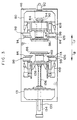
- a printing device of the present invention With reference to Figs. 1 to 5, an embodiment of a printing device of the present invention will be explained as a tire printing device hereinafter.
- a storage section 14 for storing a plurality of tires 12 at the '"R" side of Fig. 2 (which will be referred to "the "R" side” hereinafter).
- the storage section 14 is provided with a tilt platform 16 on which a plurality of the tires 12 is placed in a row.
- the tilt platform 16 is lowered at the left hand side thereof.
- a tire supply device 18 is disposed in the vicinity of the storage section 14 at the "L" side of Fig. 2 (which will be referred to as “the "L” side” hereinafter).
- the tire supply device 18 has a main body portion 22 that is installed on a floor surface 20.
- a bearing 24 At the upper portion of the main body portion 22, there is disposed a bearing 24.
- One end of a tire loading plate 28 for loading the tire 12 thereon is supported by a shaft 26 which is supported by this bearing 24, thus enabling the tire loading plate 28 to swing.
- the tire loading plate 28 is formed into a substantially V-shape.
- the main body portion 22 is provided with an air cylinder support portion 30 on the side surface thereof at the storage section 14 side.
- An air cylinder 32 is supported by the air cylinder support portion 30 so as to be able to swing.
- the tip end portion of a piston rod 34 of the air cylinder 32 is connected to the other end of the tire loading plate 28 via a pin 36.
- An operation of the air cylinder 32 is controlled by a controller 40.
- a tire loading stand 42 is provided at the "L" side of the tire supply device 18.
- the tire loading stand 42 is provided with a base plate 46 which is installed on the floor surface 20.
- a pair of guide rails 48 which extend horizontally in a direction orthogonal to the "R" and "L” directions in Fig. 2 (i.e., a thickness direction of Fig. 2 or the direction of arrow F and the direction of arrow B in Fig. 1) is mounted to the base 46.
- a transversely movable frame 50 (which will be referred to as a "frame 50" hereinafter) is supported by the guide rails 48 via linear bearings 49.
- an air cylinder 54 having a piston rod 56 whose tip end portion engages with the frame 50.
- the position of the frame 50 can be controlled both in the direction of arrow B and in the direction of arrow F.
- a plurality of guide shafts 58 is disposed vertically at the frame 50.
- a vertically moving frame 60 (which will be referred to as a "frame 60" hereinafter) is supported by the guide shafts 58 so as to be slidable.
- a screw jack 62 is disposed at the frame 50. By rotating a handle 64 of the screw jack 62, the height position of the frame 60 can be adjusted.
- a bearing 66 is disposed at the upper portion of the frame 60.
- One end of a tire loading plate 70 for loading a tire 12 thereon is supported by a shaft 68 supported by this bearing 66, thus enabling the tire loading plate 70 to swing.
- An air cylinder 72 is disposed vertically at the "R" side of the frame 60.
- the air cylinder 72 is controlled by the controller 40.
- each of the rollers 76 is disposed horizontally and has a rotation axis whose lengthwise direction corresponds to a direction orthogonal to the direction of arrow R and the direction of arrow L.
- a gate-shaped frame 78 is disposed on the floor surface 20.
- a support 80 and a support 131 (which will be described later) for forming the gate-shaped frame 78.
- the support 80 is disposed at the "F" side of Fig. 1 (which will be referred to as “the "F” side” hereinafter) of the gate-shaped frame 78 and has a bearing 82 by which a rotation axis 84 is rotatably supported.
- a bead portion support member 86 for engaging with one of the bead portions of the tire 12.
- This bead portion support member 86 is formed into the substantially same disc-shaped configuration as one of the halves of a rim which would be obtained by cutting the rim at the center portion in the widthwise direction thereof.
- a passage (not shown) which supplies air.
- One end of the air passage formed inside the bead portion support member 86 is opened outside at the "B" side in Fig. 3.
- the support 80 is provided with a motor 92 having a sprocket 90 mounted on the rotation axis thereof.
- An unillustrated sprocket is mounted to the rotation axis 84 at the other end side thereof.
- An endless chain 94 is entrained between the sprocket 90 of the motor 92 and the sprocket of the rotation axis 84.
- the rotation axis 84 can be rotated.
- the rotation of the motor 92 is controlled by the controller 40.
- a thermal transfer printer 98 is disposed at each side of the support 80 so as to interpose the rotation axis 84 therebetween.
- the thermal transfer printer 98 is provided with a base plate 100 which is mounted on the side surface of the support 80.
- a pair of guide rails 102 is mounted horizontally to the base plate 100.
- a moving base 106 is supported by the pair of the guide rails 102 by way of linear bearings 104.
- a hydraulic cylinder 108 is horizontally mounted on the base plate 100.
- One end of a piston rod 110 engages with the moving base 106.
- a take-up side reel support shaft 118 At the lower portion of the moving base 106 is provided a take-up side reel support shaft 118. To this take-up side reel support shaft 118 is detachably mounted a take-up reel 120.
- a pair of nipping rollers 122 for nipping the transfer film 114 and withdrawing the same toward the take-up reel 120.
- the nipping rollers 122 and the take-up reel 120 are rotated by an unillustrated motor so as to pull the transfer film 114 out from the supply reel 116 and take up the transfer film 114 onto the take-up reel 120. Further, the motor for rotating the nipping rollers 122 and the take-up reel 120 is connected to the controller 40 and the rotation thereof is controlled by the controller 40.
- a pair of guide rollers 124 for guiding the transfer film 114 between the pair of the nipping rollers 122 and the take-up reel 120 in a vertical direction.
- an arcuate thermal plate 126 as is shown in Fig. 5 is disposed parallel to the transfer film 114.
- a thermal plate 126 is heated by an unillustrated heater.
- the thermal transfer film 114 is constructed such that white logo marks 128 are printed on one side of a heat-resistant resin film (which side is opposite to thermal plate 126 side of the film) at a predetermined interval.
- the logo marks 128 are printed with ink that does not show transferability at the room temperature or so but shows the transferability when it is heated (e.g., at the temperature of 100°C or more).
- Ink such as rubber-based ink, synthetic resin-based ink or the like that rolls well even in a solid state is preferable.
- Registration marks 130 are printed on the transfer film 114 at the same predetermined intervals as the logo marks 128.
- the registration marks 130 are detected by an optical sensor 132 which is provided at the moving base 106.
- the optical sensor 132 is connected to the controller 40, and controlled by the controller 40 such that, for instance, the optical sensor 132 reliably detects the registration marks 130 when the transfer film 114 comes to the position (the transfer position) at which the logo marks 128 face the portions of the tire 12 on which the logo marks 128 are to be printed or transferred.
- a TV camera 133 for detecting rotation marks that are provided at the side portions of the tire 12.
- the TV camera 133 is connected to the controller 40.
- a hydraulic cylinder 134 and a pair of guide shafts 135 are disposed at another support 131.
- the pair of the guide shafts 135 is supported by a bearing disposed at the support 131 so as to be able to slide freely both in the direction of arrow F and the direction of arrow B.
- a moving frame 138 is mounted to the "F" side ends of the guide shafts 135.
- a piston rod 136 of the hydraulic cylinder 134 is mounted to the moving frame 138. By extending/retracting the piston rod 136, the moving frame 138 can be moved both in the direction of arrow F and in the direction of arrow B.
- the hydraulic cylinder 134 is controlled by the controller 40.
- the thermal transfer printer 98 is disposed at each side of the moving frame 138 so as to interpose the hydraulic cylinder 134 therebetween. Accordingly, four thermal transfer printers 98 are provided in the present embodiment.
- a bearing 140 by which a shaft having the bead portion support member 86 mounted thereon (not shown) is rotatably supported.
- a horizontal beam 142 At the upper portion of the gate-shaped frame 78 is disposed a horizontal beam 142.
- An air cylinder 144 is disposed so as to cross the beam 142 thus allowing a piston rod 146 to downwardly extend/upwardly retract.
- a stopper roller 148 At the lower end of the piston rod 146 is mounted a stopper roller 148 that abuts the tire 12 to prevent the tire 12 from moving. An operation of this air cylinder 144 is controlled by the controller 40.
- a conveying platform 150 for conveying the tire 12 having logo marks printed thereon in the direction of arrow L.
- the tires 12 on which logo marks are to be printed are placed in a row on the tilt platform 16.
- the tilt platform 16 is inclined such that the "L" side thereof is lowered, the tires 12 at the "L" side of the storage section 14 are sequentially rolled over farther in the direction of arrow L and disposed on the tire loading plate 28 of the tire supply device 18.
- each of the tires 12 which have rolled over stops at the concave portion of the V-shape.
- the tire loading plate 70 is adjusted in height beforehand by using the screw jack 62 such that the center of rotation of the tire 12 loaded thereon corresponds to that of the bead portion support member 86.
- the piston rod 136 of the hydraulic cylinder 134 provided at the support 131 is extended in the direction of arrow F, such that a pair of the bead portion support members 86 nips the tire 12 therebetween and portions in the vicinities of outer periphery of the bead portion support members 86 come into contact with the bead portions of the tire 12.
- the inside of the tire 12 is air-tightly sealed.
- air from a compressor is supplied into the tire 12 to thereby maintain the internal pressure inside of the tire 12 at a predetermined level.
- the motor 92 is operated to thereby rotate the tire 12 nipped by the bead portion support members 86.
- the take-up reel 120 and the nipping rollers 122 are rotated to thereby take up the transfer film 114 from the supply reel 116.
- the transfer film 114 is heated by the thermal plates 126, and the logo marks 128 is transferred to the side portions of the tire 12.
- the pressing pressure of the thermal plate 126 reliably acts upon the logo marks 128 of the transfer film 114 thus allowing the logo marks 128 to reliably transfer onto the side portions of the tire 12.
- a predetermined internal pressure of the tire 12 may be a minimum pressure at which the logo marks 128 can reliably be transferred.
- liquid ink since liquid ink is not used in printing, clear indications can be obtained without blurring.
- the logo marks 128 can simultaneously be printed at four positions of the tire 12 .
- the piston rods 110 of the hydraulic cylinders 108 are withdrawn, such that the thermal plates 126 are moved in a direction in which the thermal plates 126 separate from the tire 12.
- a switch valve which is disposed on a path of an unilllustrated pipe is switched, so that the inside of the tire 12 communicates with the atmosphere and the internal pressure of the tire 12 is reduced to an atmospheric pressure. Thereafter, the piston rod 136 of the hydraulic cylinder 134 is retracted, whereby the bead portion support member 86 at the support 131 side is separated from the tire 12.
- the tire 12 on which the logo marks 128 have been printed rolls over onto the conveying platform 150 in the direction of arrow L.
- the logo marks 128 can automatically be printed at four positions per a single tire, it is possible to print the logo marks 128 effectively on a number of the tires 12.
- the logo marks 128 are provided on the transfer film 114 at a predetermined interval.
- ink may be applied to the entire surface of one side of the film 114.
- the surface of the thermal plate 126 may be formed into a letterpress printing plate or an intaglio printing plate-like structure so that indications such as logo marks, letters, numbers, patterns, and the like can be printed on the tire 12 in a manner of the letterpress or intaglio printing.
- the tire 12 was used as an object to be printed.
- the present invention is not limited to this tire.
- indications can be printed on any toroidal-shaped bodies except a tire, such as a tube, a roll, a float, a rubber boat main portion, and the like.
- an excellent effect can be provided in that indications can be printed clearly and effectively on the side portions of a toroidal-shaped body such as a tire.
Landscapes
- Engineering & Computer Science (AREA)
- Mechanical Engineering (AREA)
- Tyre Moulding (AREA)
- Labeling Devices (AREA)
Abstract
Description
Further, to the intermediate portion of the air pipe is connected a switch valve (not shown), and to the other end of the air pipe is connected an air compressor (not shown). Moreover, the switch valve is controlled by the
Claims (21)
- A printing device, comprising:a support means for supporting a toroidal-shaped body;a plurality of transfer film supply means for supplying a transfer film, on the surface of which ink has been applied, to portions in the vicinities of the toroidal-shaped body, the ink exhibiting thermal transferability when heated; anda plurality of transfer means, disposed so as to correspond to said transfer film supply means, for heating said transfer film while pressing the ink applied surface of said transfer film onto a surface of said toroidal-shaped body.
- The printing device according to claim 1, wherein said support means has a pressure imparting means for imparting pressure to the surface at the opposite side of a printing surface on which printing is to be carried out, of the toroidal-shaped body.
- The printing device according to claim 2, further comprising:a storage section for storing a plurality of toroidal-shaped bodies; anda conveying means for supplying the toroidal-shaped bodies stored in said storage section to said support means and for discharging said toroidal-shaped bodies for which printing has been completed from said support means.
- The printing device according to claim 3, wherein said support means has a detection means for detecting a specified position of said toroidal-shaped body, and positions the toroidal-shaped body at a transfer position, at which ink transfer is to be carried out, on the basis of said specified position detected by said detection means.
- The printing device according to claim 4, wherein said transfer film supply means has another detection means for detecting a specified position of said transfer film, and positions the transfer film at a transfer position, at which ink transfer is to be carried out, on the basis of said specified position detected by said another detection means.
- The printing device according to claim 5, wherein said transfer film supply means supplies said transfer film to a portion in the vicinity of the toroidal-shaped body such that the transfer position of said transfer film corresponds to the transfer position of said toroidal-shaped body.
- The printing device according to claim 1, wherein said toroidal-shaped body is a tire rim assembly in which a tire is attached to a rim, and said support means supports the rim.
- The printing device according to claim 1, further comprising:a storage section for storing a plurality of toroidal-shaped bodies; anda conveying means for supplying the toroidal-shaped bodies stored in said storage section to said support means and for discharging the toroidal-shaped bodies for which printing has been completed from said support means.
- The printing device according to claim 8, wherein said support means has a detection means for detecting a specified position of said toroidal-shaped body, and positions the toroidal-shaped body at a transfer position, at which ink transfer is to be carried out, on the basis of said specified position detected by said detection means.
- The printing device according to claim 9, wherein said transfer film supply means has another detection means for detecting a specified position of said transfer film, and positions the transfer film at a transfer position, at which ink transfer is to be carried out, on the basis of said specified position detected by said another detection means.
- The printing device according to claim 10, wherein said transfer film supply means supplies said transfer film to a portion in the vicinity of the toroidal-shaped body such that the transfer position of said transfer film corresponds to the transfer position of said toroidal-shaped body.
- A printing device, comprising:a support means for supporting a toroidal-shaped body such that a printing region, in which printing is to be carried out, of the surface of the toroidal-shaped body is positioned at a predetermined position;a transfer film supply means for supplying a transfer film which contains a transfer region in which ink having thermal transferability is applied on the surface thereof, such that said transfer region of the transfer film corresponds to the printing region of the surface of the toroidal-shaped body; anda plurality of transfer means which is disposed so as to correspond to said transfer film supply means and which heats said transfer region of said transfer film and transfers thermally transferable ink onto said printing region of said surface of said toroidal-shaped body.
- The printing device according to claim 12, wherein said support means has a pressure imparting means for imparting pressure to the surface at the opposite side of a printing surface on which printing is to be carried out, of the toroidal-shaped body.
- The printing device according to claim 12, further comprising:a storage section for storing a plurality of toroidal-shaped bodies; anda conveying means for supplying the toroidal-shaped bodies stored in said storage section to said support means and for discharging the toroidal-shaped bodies for which printing has been completed from said support means.
- The printing device according to claim 12, wherein said support means detects a specified position of said toroidal-shaped body, and positions the toroidal-shaped body at a transfer position, at which ink transfer is to be carried out, on the basis of the specified position thus detected.
- The printing device according to claim 12, wherein said transfer film supply means detects a specified position of said transfer film, and positions the transfer film at a transfer position, at which ink transfer is to be carried out, on the basis of said specified position thus detected.
- A printing method, comprising the steps of:(a) imparting pressure to the surface at the opposite side of a surface on which printing is to be carried out, of a toroidal-shaped body;(b) pressing a transfer film being in a state of being heated and having ink that generates transferability due to heating on the surface thereof, to a printing surface on which printing is to be carried out, the surface at the opposite of the printing surface being under a pressure; and(c) thereby transferring the ink of the transfer film onto the printing surface.
- The printing method according to claim 17, further comprising a step of simultaneously transferring said ink of said transfer film onto a plurality of positions of said toroidal-shaped body.
- The printing device according to claim 17, further comprising a step of disposing the transfer film such that the transfer film faces each of axial direction side surfaces of the toroidal-shaped body and then simultaneously transferring the ink of the transfer film on both of the axial direction side surfaces of the toroidal-shaped body.
- The printing device according to claim 17, further comprising a step of sequentially shifting said transfer film formed in a strip and transferring said ink onto said transfer film.
- The printing device according to claim 17, wherein said toroidal-shaped body is a tire rim assembly in which a tire is attached to a rim and further comprising a step of carrying out said transfer in a state in which internal pressure is imparted into said tire.
Applications Claiming Priority (5)
| Application Number | Priority Date | Filing Date | Title |
|---|---|---|---|
| JP2000182111 | 2000-06-16 | ||
| JP2000182111 | 2000-06-16 | ||
| JP2000018211 | 2000-06-16 | ||
| JP2001137115A JP4885370B2 (en) | 2000-06-16 | 2001-05-08 | Printing apparatus and printing method |
| JP2001137115 | 2001-05-08 |
Publications (4)
| Publication Number | Publication Date |
|---|---|
| EP1167030A2 true EP1167030A2 (en) | 2002-01-02 |
| EP1167030A8 EP1167030A8 (en) | 2002-03-13 |
| EP1167030A3 EP1167030A3 (en) | 2004-10-27 |
| EP1167030B1 EP1167030B1 (en) | 2011-02-09 |
Family
ID=26594140
Family Applications (1)
| Application Number | Title | Priority Date | Filing Date |
|---|---|---|---|
| EP01304895A Expired - Lifetime EP1167030B1 (en) | 2000-06-16 | 2001-06-05 | Printing device and printing method |
Country Status (4)
| Country | Link |
|---|---|
| US (1) | US6568320B2 (en) |
| EP (1) | EP1167030B1 (en) |
| JP (1) | JP4885370B2 (en) |
| DE (1) | DE60143999D1 (en) |
Cited By (2)
| Publication number | Priority date | Publication date | Assignee | Title |
|---|---|---|---|---|
| FR2891194A1 (en) * | 2005-09-28 | 2007-03-30 | Cer Soc Par Actions Simplifiee | Marking machine for cylindrical objects, e.g. cosmetic and hygiene products or building products, has separate control and alignment cameras, the alignment camera being used to align the object prior to printing |
| WO2011097621A1 (en) | 2010-02-08 | 2011-08-11 | Micro-Poise Measurement Systems, Llc | Tire marking apparatus |
Families Citing this family (23)
| Publication number | Priority date | Publication date | Assignee | Title |
|---|---|---|---|---|
| ITTO20020356A1 (en) * | 2002-04-24 | 2003-10-24 | Eidos Spa | MACHINE FOR PRINTING IMAGES ON ARTICLES. |
| JP4999458B2 (en) * | 2004-09-10 | 2012-08-15 | 株式会社秀峰 | Method for printing on curved surface and printed curved surface by the same |
| CN100400300C (en) * | 2006-01-10 | 2008-07-09 | 美可达电子影像有限公司 | cup baking machine |
| JP5127425B2 (en) * | 2007-12-18 | 2013-01-23 | 株式会社ブリヂストン | Tire labeling method and apparatus |
| CN102905907B (en) | 2010-06-02 | 2014-12-24 | 惠普发展公司,有限责任合伙企业 | Tension module for wide format inkjet printers |
| JP5683908B2 (en) | 2010-11-08 | 2015-03-11 | 株式会社ブリヂストン | Tire surface printing method and tire |
| JP2012158297A (en) * | 2011-02-02 | 2012-08-23 | Bridgestone Corp | Tire and tire manufacturing method |
| CN102729669A (en) * | 2011-04-02 | 2012-10-17 | 北京厚明德新材料包装有限公司 | Printing method and equipment of compound thermal shrinkage film |
| CN102390166B (en) * | 2011-07-21 | 2013-07-17 | 汕头市东田转印有限公司 | Equipment and method for performing transfer printing on plate surface |
| JP5684198B2 (en) * | 2012-05-18 | 2015-03-11 | 株式会社ブリヂストン | Tire surface printing method and tire printing apparatus |
| US9321256B2 (en) | 2012-08-14 | 2016-04-26 | Illinois Tool Works Inc. | System for applying images to planar surfaces of a target object |
| CN103112244A (en) * | 2012-12-10 | 2013-05-22 | 苏州一致电子制程有限公司 | Blanking device of thermal transfer printing machine |
| CN104260559B (en) * | 2014-09-10 | 2016-08-31 | 合肥汉闻数字印刷设备有限公司 | A kind of rotational structure for tire digital printer |
| CN104742510A (en) * | 2015-02-16 | 2015-07-01 | 中信戴卡股份有限公司 | Workstation rotating wheel printing fixture |
| CN105236071A (en) * | 2015-11-11 | 2016-01-13 | 万达工业(始兴)有限公司 | Automatic pad printing machine of tire |
| CN106005646A (en) * | 2016-07-01 | 2016-10-12 | 无锡康柏斯机械科技有限公司 | Anti-offsetting device for label outside tire |
| JP2018132365A (en) * | 2017-02-14 | 2018-08-23 | 株式会社神戸製鋼所 | Marking device |
| CN107336532A (en) * | 2017-07-21 | 2017-11-10 | 中信戴卡股份有限公司 | A kind of airtight marking unit of double |
| CN107825870A (en) * | 2017-10-31 | 2018-03-23 | 合肥汉闻数字印刷设备有限公司 | A kind of device that processing is continuously printed for tire |
| CN107804075A (en) * | 2017-10-31 | 2018-03-16 | 合肥汉闻数字印刷设备有限公司 | A kind of novel tire printer |
| CN107757142A (en) * | 2017-10-31 | 2018-03-06 | 合肥汉闻数字印刷设备有限公司 | A kind of equipment for tire printing processing |
| US10625896B2 (en) * | 2018-03-01 | 2020-04-21 | Akron Special Machinery, Inc. | Decal marker system |
| DE102023001728A1 (en) * | 2023-04-28 | 2024-10-31 | Dieffenbacher Maschinenfabrik Gmbh, Zaisenhausen | Press and method for finishing or laminating substrates and method for operating a press |
Family Cites Families (15)
| Publication number | Priority date | Publication date | Assignee | Title |
|---|---|---|---|---|
| DE2507500C2 (en) * | 1975-02-21 | 1978-03-23 | Carl Schenck Ag, 6100 Darmstadt | Device for marking a rotatable test item |
| JPS52110504A (en) * | 1976-03-15 | 1977-09-16 | Yuseisho Denpa Kenkyusho | Preecompressor for reducing spectrum distortion |
| JPS5925281B2 (en) * | 1976-12-20 | 1984-06-16 | 日本コロムビア株式会社 | Method and device for forming display section of record disc |
| SE404896B (en) * | 1977-04-05 | 1978-11-06 | Stabil Mek Verk | DEVICE FOR APPLYING A BAND-SHAPED MATERIAL ON THE SIDE OF A ROTATING SYMMETRIC BODY |
| US4397710A (en) * | 1982-01-22 | 1983-08-09 | The Meyercord Co. | Machine for applying indicia to tapered or straight cylindrical articles |
| JPS62152755A (en) * | 1985-12-27 | 1987-07-07 | Yokohama Rubber Co Ltd:The | Printing apparatus for tire structure material |
| DE3733796A1 (en) * | 1987-10-07 | 1989-04-20 | Sipra Patent Beteiligung | THREAD CHANGING DEVICE, ESPECIALLY FOR KNITTING MACHINES |
| JP2917284B2 (en) * | 1989-03-10 | 1999-07-12 | スズキ株式会社 | How to mark light spots on wheels |
| JPH04223142A (en) * | 1990-12-26 | 1992-08-13 | Bridgestone Corp | Method for applying stripe pattern onto side wall of tire and its device |
| US5364688A (en) * | 1993-03-08 | 1994-11-15 | Mahn Jr John | Heat activated transfer for elastomeric materials |
| US5600359A (en) * | 1993-07-14 | 1997-02-04 | Sony Corporation | Thermal transfer printing method and apparatus |
| IT1289701B1 (en) * | 1996-11-29 | 1998-10-16 | Bridgestone Firestone Tech | METHOD FOR MARKING A TIRE |
| US5932052A (en) * | 1997-02-10 | 1999-08-03 | Brown; Russell S | Process for applying indicia onto an elastomeric component |
| JPH10329402A (en) * | 1997-06-03 | 1998-12-15 | Bridgestone Corp | Tire surface printing method |
| JPH11278020A (en) * | 1998-03-26 | 1999-10-12 | Bridgestone Corp | Marking inspection device |
-
2001
- 2001-05-08 JP JP2001137115A patent/JP4885370B2/en not_active Expired - Fee Related
- 2001-06-05 EP EP01304895A patent/EP1167030B1/en not_active Expired - Lifetime
- 2001-06-05 DE DE60143999T patent/DE60143999D1/en not_active Expired - Lifetime
- 2001-06-13 US US09/878,945 patent/US6568320B2/en not_active Expired - Lifetime
Cited By (7)
| Publication number | Priority date | Publication date | Assignee | Title |
|---|---|---|---|---|
| FR2891194A1 (en) * | 2005-09-28 | 2007-03-30 | Cer Soc Par Actions Simplifiee | Marking machine for cylindrical objects, e.g. cosmetic and hygiene products or building products, has separate control and alignment cameras, the alignment camera being used to align the object prior to printing |
| EP1769916A3 (en) * | 2005-09-28 | 2007-08-29 | Cer | Device and process for marking cylindrical objects |
| WO2011097621A1 (en) | 2010-02-08 | 2011-08-11 | Micro-Poise Measurement Systems, Llc | Tire marking apparatus |
| CN102770600A (en) * | 2010-02-08 | 2012-11-07 | 精衡测量系统有限公司 | Tire marking apparatus |
| EP2534304A4 (en) * | 2010-02-08 | 2013-07-24 | Micro Poise Measurement Systems Llc | TIRE MARKING APPARATUS |
| CN102770600B (en) * | 2010-02-08 | 2016-01-20 | 精衡测量系统有限公司 | tire marking device |
| US9440405B2 (en) | 2010-02-08 | 2016-09-13 | Micro-Poise Measurement Systems, Llc | Tire marking apparatus |
Also Published As
| Publication number | Publication date |
|---|---|
| DE60143999D1 (en) | 2011-03-24 |
| EP1167030B1 (en) | 2011-02-09 |
| JP2002068154A (en) | 2002-03-08 |
| US20020005123A1 (en) | 2002-01-17 |
| US6568320B2 (en) | 2003-05-27 |
| JP4885370B2 (en) | 2012-02-29 |
| EP1167030A8 (en) | 2002-03-13 |
| EP1167030A3 (en) | 2004-10-27 |
Similar Documents
| Publication | Publication Date | Title |
|---|---|---|
| US6568320B2 (en) | Heat transfer printing device and method for printing on toroidal-shaped bodies | |
| CN104284850B (en) | Endless flexible belts for printing systems | |
| US7503256B2 (en) | Variable cut-off offset press system and method of operation | |
| JP4616451B2 (en) | Print quality inspection device | |
| US6142073A (en) | Method and apparatus for exchanging a roll of a printing press | |
| CN87103498A (en) | Converting of paper and other webs | |
| JP5638167B2 (en) | A method of attaching and registering a printing plate to a plate cylinder of a multicolor offset printing press | |
| CN113442555A (en) | Flexible plate printing machine with accurate color register and control method | |
| KR0181516B1 (en) | Engraving drum cooling device for reclamatory printing paper feed | |
| EP3711952A1 (en) | Intermittent printing apparatus | |
| CA1303900C (en) | Flexographic printing machine, especially for flexographic web printing | |
| CN211971243U (en) | Unwinding device is received to coiled material | |
| KR102838308B1 (en) | Offset printing system with sensors capable of identifying defective products | |
| ES2357544T3 (en) | PRINTING DEVICE AND PRINTING METHOD. | |
| CN220078084U (en) | Conveying device of high-speed printing machine | |
| CN223407641U (en) | A device for developing a cross-section color or spot color thermal transfer process | |
| CN223520504U (en) | Transfer printing mark and printing equipment | |
| JP7841282B2 (en) | Printing apparatus, method for controlling a printing apparatus | |
| JP3007729B2 (en) | Printing plate mounting system | |
| CN120773459A (en) | Sheet, sheet printing method, sheet printing apparatus, and inflated product | |
| JPH115291A (en) | Multicolor printing apparatus and duplex printing method | |
| KR101585860B1 (en) | Digital printing machine | |
| JP2004277088A (en) | Position adjusting method for beltlike body, printing device equipped with it, and position adjusting method for beltlike body | |
| GB2243330A (en) | Screen printing apparatus | |
| KR20240028735A (en) | Printing device and printing method |
Legal Events
| Date | Code | Title | Description |
|---|---|---|---|
| PUAI | Public reference made under article 153(3) epc to a published international application that has entered the european phase |
Free format text: ORIGINAL CODE: 0009012 |
|
| AK | Designated contracting states |
Kind code of ref document: A2 Designated state(s): AT BE CH CY DE DK ES FI FR GB GR IE IT LI LU MC NL PT SE TR |
|
| AX | Request for extension of the european patent |
Free format text: AL;LT;LV;MK;RO;SI |
|
| PUAL | Search report despatched |
Free format text: ORIGINAL CODE: 0009013 |
|
| AK | Designated contracting states |
Kind code of ref document: A3 Designated state(s): AT BE CH CY DE DK ES FI FR GB GR IE IT LI LU MC NL PT SE TR |
|
| AX | Request for extension of the european patent |
Extension state: AL LT LV MK RO SI |
|
| RIC1 | Information provided on ipc code assigned before grant |
Ipc: 7B 44C 1/17 B Ipc: 7B 41F 16/00 A Ipc: 7B 60C 13/00 B Ipc: 7B 41F 17/00 B |
|
| 17P | Request for examination filed |
Effective date: 20050414 |
|
| AKX | Designation fees paid |
Designated state(s): DE ES FR GB IT |
|
| GRAP | Despatch of communication of intention to grant a patent |
Free format text: ORIGINAL CODE: EPIDOSNIGR1 |
|
| GRAS | Grant fee paid |
Free format text: ORIGINAL CODE: EPIDOSNIGR3 |
|
| GRAA | (expected) grant |
Free format text: ORIGINAL CODE: 0009210 |
|
| AK | Designated contracting states |
Kind code of ref document: B1 Designated state(s): DE ES FR GB IT |
|
| REG | Reference to a national code |
Ref country code: GB Ref legal event code: FG4D |
|
| REF | Corresponds to: |
Ref document number: 60143999 Country of ref document: DE Date of ref document: 20110324 Kind code of ref document: P |
|
| REG | Reference to a national code |
Ref country code: DE Ref legal event code: R096 Ref document number: 60143999 Country of ref document: DE Effective date: 20110324 |
|
| REG | Reference to a national code |
Ref country code: ES Ref legal event code: FG2A Ref document number: 2357544 Country of ref document: ES Kind code of ref document: T3 Effective date: 20110427 |
|
| PLBE | No opposition filed within time limit |
Free format text: ORIGINAL CODE: 0009261 |
|
| STAA | Information on the status of an ep patent application or granted ep patent |
Free format text: STATUS: NO OPPOSITION FILED WITHIN TIME LIMIT |
|
| 26N | No opposition filed |
Effective date: 20111110 |
|
| REG | Reference to a national code |
Ref country code: DE Ref legal event code: R097 Ref document number: 60143999 Country of ref document: DE Effective date: 20111110 |
|
| PGFP | Annual fee paid to national office [announced via postgrant information from national office to epo] |
Ref country code: GB Payment date: 20120530 Year of fee payment: 12 |
|
| PGFP | Annual fee paid to national office [announced via postgrant information from national office to epo] |
Ref country code: IT Payment date: 20120618 Year of fee payment: 12 |
|
| PGFP | Annual fee paid to national office [announced via postgrant information from national office to epo] |
Ref country code: ES Payment date: 20120621 Year of fee payment: 12 |
|
| GBPC | Gb: european patent ceased through non-payment of renewal fee |
Effective date: 20130605 |
|
| PG25 | Lapsed in a contracting state [announced via postgrant information from national office to epo] |
Ref country code: GB Free format text: LAPSE BECAUSE OF NON-PAYMENT OF DUE FEES Effective date: 20130605 |
|
| PG25 | Lapsed in a contracting state [announced via postgrant information from national office to epo] |
Ref country code: IT Free format text: LAPSE BECAUSE OF NON-PAYMENT OF DUE FEES Effective date: 20130605 |
|
| REG | Reference to a national code |
Ref country code: ES Ref legal event code: FD2A Effective date: 20140707 |
|
| REG | Reference to a national code |
Ref country code: DE Ref legal event code: R082 Ref document number: 60143999 Country of ref document: DE Representative=s name: BARDEHLE PAGENBERG PARTNERSCHAFT MBB PATENTANW, DE |
|
| REG | Reference to a national code |
Ref country code: FR Ref legal event code: CA Effective date: 20140812 |
|
| REG | Reference to a national code |
Ref country code: DE Ref legal event code: R081 Ref document number: 60143999 Country of ref document: DE Owner name: BRIDGESTONE CORPORATION, JP Free format text: FORMER OWNER: BRIDGESTONE CORP., TOKIO/TOKYO, JP Effective date: 20140828 Ref country code: DE Ref legal event code: R082 Ref document number: 60143999 Country of ref document: DE Representative=s name: BARDEHLE PAGENBERG PARTNERSCHAFT MBB PATENTANW, DE Effective date: 20140828 |
|
| PG25 | Lapsed in a contracting state [announced via postgrant information from national office to epo] |
Ref country code: ES Free format text: LAPSE BECAUSE OF NON-PAYMENT OF DUE FEES Effective date: 20130606 |
|
| REG | Reference to a national code |
Ref country code: FR Ref legal event code: PLFP Year of fee payment: 15 |
|
| PGFP | Annual fee paid to national office [announced via postgrant information from national office to epo] |
Ref country code: DE Payment date: 20150619 Year of fee payment: 15 |
|
| PGFP | Annual fee paid to national office [announced via postgrant information from national office to epo] |
Ref country code: FR Payment date: 20150619 Year of fee payment: 15 |
|
| REG | Reference to a national code |
Ref country code: DE Ref legal event code: R119 Ref document number: 60143999 Country of ref document: DE |
|
| REG | Reference to a national code |
Ref country code: FR Ref legal event code: ST Effective date: 20170228 |
|
| PG25 | Lapsed in a contracting state [announced via postgrant information from national office to epo] |
Ref country code: DE Free format text: LAPSE BECAUSE OF NON-PAYMENT OF DUE FEES Effective date: 20170103 Ref country code: FR Free format text: LAPSE BECAUSE OF NON-PAYMENT OF DUE FEES Effective date: 20160630 |