EP1166884A1 - Spray gun air cap - Google Patents
Spray gun air cap Download PDFInfo
- Publication number
- EP1166884A1 EP1166884A1 EP01110800A EP01110800A EP1166884A1 EP 1166884 A1 EP1166884 A1 EP 1166884A1 EP 01110800 A EP01110800 A EP 01110800A EP 01110800 A EP01110800 A EP 01110800A EP 1166884 A1 EP1166884 A1 EP 1166884A1
- Authority
- EP
- European Patent Office
- Prior art keywords
- air
- cap
- horn
- outer side
- passages
- Prior art date
- Legal status (The legal status is an assumption and is not a legal conclusion. Google has not performed a legal analysis and makes no representation as to the accuracy of the status listed.)
- Withdrawn
Links
- 239000007921 spray Substances 0.000 title claims abstract description 32
- 239000002184 metal Substances 0.000 claims description 3
- 229910001369 Brass Inorganic materials 0.000 claims description 2
- 239000010951 brass Substances 0.000 claims description 2
- 239000003973 paint Substances 0.000 description 4
- 230000000712 assembly Effects 0.000 description 3
- 238000000429 assembly Methods 0.000 description 3
- 238000000889 atomisation Methods 0.000 description 2
- 239000012530 fluid Substances 0.000 description 2
- 238000009825 accumulation Methods 0.000 description 1
Images

Classifications
-
- B—PERFORMING OPERATIONS; TRANSPORTING
- B05—SPRAYING OR ATOMISING IN GENERAL; APPLYING FLUENT MATERIALS TO SURFACES, IN GENERAL
- B05B—SPRAYING APPARATUS; ATOMISING APPARATUS; NOZZLES
- B05B7/00—Spraying apparatus for discharge of liquids or other fluent materials from two or more sources, e.g. of liquid and air, of powder and gas
- B05B7/0081—Apparatus supplied with low pressure gas, e.g. "hvlp"-guns; air supplied by a fan
-
- B—PERFORMING OPERATIONS; TRANSPORTING
- B05—SPRAYING OR ATOMISING IN GENERAL; APPLYING FLUENT MATERIALS TO SURFACES, IN GENERAL
- B05B—SPRAYING APPARATUS; ATOMISING APPARATUS; NOZZLES
- B05B7/00—Spraying apparatus for discharge of liquids or other fluent materials from two or more sources, e.g. of liquid and air, of powder and gas
- B05B7/02—Spray pistols; Apparatus for discharge
- B05B7/08—Spray pistols; Apparatus for discharge with separate outlet orifices, e.g. to form parallel jets, i.e. the axis of the jets being parallel, to form intersecting jets, i.e. the axis of the jets converging but not necessarily intersecting at a point
- B05B7/0807—Spray pistols; Apparatus for discharge with separate outlet orifices, e.g. to form parallel jets, i.e. the axis of the jets being parallel, to form intersecting jets, i.e. the axis of the jets converging but not necessarily intersecting at a point to form intersecting jets
- B05B7/0815—Spray pistols; Apparatus for discharge with separate outlet orifices, e.g. to form parallel jets, i.e. the axis of the jets being parallel, to form intersecting jets, i.e. the axis of the jets converging but not necessarily intersecting at a point to form intersecting jets with at least one gas jet intersecting a jet constituted by a liquid or a mixture containing a liquid for controlling the shape of the latter
-
- B—PERFORMING OPERATIONS; TRANSPORTING
- B05—SPRAYING OR ATOMISING IN GENERAL; APPLYING FLUENT MATERIALS TO SURFACES, IN GENERAL
- B05B—SPRAYING APPARATUS; ATOMISING APPARATUS; NOZZLES
- B05B7/00—Spraying apparatus for discharge of liquids or other fluent materials from two or more sources, e.g. of liquid and air, of powder and gas
- B05B7/02—Spray pistols; Apparatus for discharge
- B05B7/06—Spray pistols; Apparatus for discharge with at least one outlet orifice surrounding another approximately in the same plane
- B05B7/062—Spray pistols; Apparatus for discharge with at least one outlet orifice surrounding another approximately in the same plane with only one liquid outlet and at least one gas outlet
- B05B7/066—Spray pistols; Apparatus for discharge with at least one outlet orifice surrounding another approximately in the same plane with only one liquid outlet and at least one gas outlet with an inner liquid outlet surrounded by at least one annular gas outlet
Definitions
- the invention relates generally to spray gun nozzles, and more particularly to air caps for high volume low pressure air atomization paint spray gun nozzle assemblies.
- Spray gun nozzle assemblies including those used in high volume low pressure atomization paint spray guns, are known generally.
- the known spray gun nozzle assembly air caps also comprise two air horns protruding from an outer side thereof on opposite sides of the cap opening.
- the air horns each include one or more horn air orifices that emit corresponding air jets that converge upon and shape an expanding conical atomized fluid flow dispensed from the cap opening into a generally flat fan shape.
- An object of the present invention is to provide novel air caps that improve upon and overcome problems in the art.
- Another object of the invention is to provide novel air caps that are economical and reliable.
- a further object of the invention is to provide novel spray gun nozzle air caps that produce improved spray patterns.
- Yet another object of the invention is to provide novel spray nozzle air caps that produce spray patterns having reduced spray density toward outer end portions thereof.
- a more particular object of the invention is to provide novel spray gun air caps comprising an axial passage with a cap opening on an outer side thereof, first and second air horns protruding from the outer side of the air cap on opposite sides of the cap opening, first and second diverging air passages disposed in the air cap having corresponding orifices on the outer side thereof, the first and second diverging air passages disposed on opposite sides of the cap opening and aligned generally perpendicular to the first and second air horns.
- Another more particular object of the invention is to provide novel air caps for HVLP spray gun nozzle assemblies, comprising a body member having an axial passage with a cap opening on an outer side thereof, first and second air horns protruding from the outer side ofthe body member on opposite sides of the cap opening, the first and second air horns having corresponding horn air passages therein, first and second diverging air passages extending through the body member having corresponding orifices on the outer side thereof, the first and second diverging air passages diverging from the passage axis in a direction away from the outer side of the body member, the first and second diverging air passages disposed on opposite sides of the cap opening and aligned perpendicular to the horn air passages.
- Yet another more particular object of the invention is to provide novel improvements in HVLP spray gun air caps having an axial passage with a cap opening on an outer side thereof and first and second air horns protruding therefrom on diametrically opposite sides of the cap opening, comprising first and second air passages disposed in the air cap having corresponding first and second orifices on the outer side thereof, the first and second air passages disposed on opposite sides of the cap opening generally perpendicular to the alignment of the first and second air horns, and the first and second air passages diverging from the passage axis in a direction away from the outer side of the air cap.
- the exemplary air cap is for an exemplary HVLP spray gun nozzle assembly application of the well known type disclosed generally in the referenced U.S. Patent No. 5,344,078 entitled "Nozzle Assembly for HVLP Spray Gun".
- the air caps of the present invention may however be used in applications other than HVLP spray guns.
- the air cap comprises a body member 10 having an axial passage with a cap opening 12 on an outer side 14 thereof.
- the axial passage extends through the air cap and preferably has one or more a substantially conical surface portions 16 disposed about the cap opening 12 on an inner side of the body member.
- the air cap comprises first and second air horns 20 and 30 protruding from the outer side 14 thereof on opposite sides of the cap opening 12.
- the first and second air horns each generally include one or more horn air passages with corresponding horn orifices facing generally toward the passage axis.
- the exemplary first air horn includes first and second horn air passages disposed therein with corresponding horn orifices 22 and 24, and the exemplary second air horn includes first and second horn air passages disposed therein with corresponding horn orifices 32 and 34.
- the horn air passages of the first and second air horns are preferably arranged symmetrically about the cap opening and are directed toward the passage axis, generally away from the outer side of the body member.
- the horn air passages of the first and second air horns communicate with corresponding air flow passages 21 and 31, which supply air thereto.
- a first pair of air passages are disposed in the air cap having corresponding orifices 16 and 17 on the outer side thereof near the first air horn 20 on opposite sides of the horn orifices 22 and 24 thereof, and a second pair of air passages are disposed in the air cap having corresponding orifices 18 and 19 on the outer side thereof near the second air horn 30 on opposite sides of the horn orifices 32 and 34 thereof.
- the orifices 16 and 17 are disposed generally between the cap opening 12 and the first air horn 20, and the orifices 18 and 19 are disposed generally between the cap opening 12 and the second air horn 30.
- the air cap further comprises first and second diverging air passages 40 and 50 disposed in the body member 10 on opposite sides of the cap opening 12, preferably symmetrically thereabout, with corresponding orifices on the outer side thereof.
- the diverging air passages having corresponding orifices 41 and 51 on the outer side 14 of the body member aligned generally perpendicular to the alignment of the first and second air horns, and particularly the alignment of the horn air passages thereof.
- the first and second diverging air passages 40 and 50 each diverge at an angle ⁇ measured from the passage axis through the cap opening between approximately 20 degrees and approximately 70 degrees.
- the angle ⁇ is approximately 45 degrees.
- Air jets emitted from the first and second diverging air passages 40 and 50 increase the width of the spray pattern and reduce the spray density at opposite end portions thereof.
- the spray pattern for a given application may be optimized by appropriately selecting the angle of the passages 40 and 50 relative to the passage axis, the spacing of the corresponding orifices from the cap opening, the diameters of the orifices, and the corresponding air flow rates, all of which may be determined without undue experimentation by those of ordinary skill in the art based on the disclosure herein.
- the orifice diameter of the passages 40 and 50 is approximately 1.15 mm
- the diameters of the horn orifices 22 and 32 is approximately 2.20 mm
- the diameters of the horn orifices 24 and 34 is approximately 1.80 mm.
- the exemplary air cap is a unitary metal member, formed for example of brass.
Landscapes
- Nozzles (AREA)
Abstract
Description
- The invention relates generally to spray gun nozzles, and more particularly to air caps for high volume low pressure air atomization paint spray gun nozzle assemblies.
- Spray gun nozzle assemblies, including those used in high volume low pressure atomization paint spray guns, are known generally. U.S. Patent No. 5,344,078 entitled "Nozzle Assembly for HVLP Spray Gun", assigned commonly with the present application, for example discloses a spray gun nozzle assembly comprising a fluid tip protruding into a cap opening of an air cap from an inner side thereof to form a generally conical annulus therebetween. See generally U.S. Patent No. 5,090,623 entitled "Paint Spray Gun", also assigned commonly herewith.
- The known spray gun nozzle assembly air caps also comprise two air horns protruding from an outer side thereof on opposite sides of the cap opening. The air horns each include one or more horn air orifices that emit corresponding air jets that converge upon and shape an expanding conical atomized fluid flow dispensed from the cap opening into a generally flat fan shape. U.S. Patents Nos. 5,344,078 and 5,090,623.
- It is also known to provide pairs of relatively small air passages having orifices on the outer side of the air cap between the cap opening and each of the air horns. The small air passages direct air jets on either side of the air jets emitted from the orifices of the air horns to reduce paint accumulation on the air cap and to help transport spray toward the target. U.S. Patent No. 5,344,078.
- An object of the present invention is to provide novel air caps that improve upon and overcome problems in the art.
- Another object of the invention is to provide novel air caps that are economical and reliable.
- A further object of the invention is to provide novel spray gun nozzle air caps that produce improved spray patterns.
- It is another object of the invention to provide novel spray gun nozzle air caps that produce spray patterns having increased width.
- Yet another object of the invention is to provide novel spray nozzle air caps that produce spray patterns having reduced spray density toward outer end portions thereof.
- A more particular object of the invention is to provide novel spray gun air caps comprising an axial passage with a cap opening on an outer side thereof, first and second air horns protruding from the outer side of the air cap on opposite sides of the cap opening, first and second diverging air passages disposed in the air cap having corresponding orifices on the outer side thereof, the first and second diverging air passages disposed on opposite sides of the cap opening and aligned generally perpendicular to the first and second air horns.
- Another more particular object of the invention is to provide novel air caps for HVLP spray gun nozzle assemblies, comprising a body member having an axial passage with a cap opening on an outer side thereof, first and second air horns protruding from the outer side ofthe body member on opposite sides of the cap opening, the first and second air horns having corresponding horn air passages therein, first and second diverging air passages extending through the body member having corresponding orifices on the outer side thereof, the first and second diverging air passages diverging from the passage axis in a direction away from the outer side of the body member, the first and second diverging air passages disposed on opposite sides of the cap opening and aligned perpendicular to the horn air passages.
- Yet another more particular object of the invention is to provide novel improvements in HVLP spray gun air caps having an axial passage with a cap opening on an outer side thereof and first and second air horns protruding therefrom on diametrically opposite sides of the cap opening, comprising first and second air passages disposed in the air cap having corresponding first and second orifices on the outer side thereof, the first and second air passages disposed on opposite sides of the cap opening generally perpendicular to the alignment of the first and second air horns, and the first and second air passages diverging from the passage axis in a direction away from the outer side of the air cap.
- These and other objects, aspects, features and advantages of the present invention will become more fully apparent upon careful consideration of the following Detailed Description of the Invention and the accompanying Drawings, which may be disproportionate for ease of understanding, wherein like structure and steps are referenced generally by corresponding numerals and indicators.
-
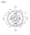
- FIG. 1 is a plan view of a spray gun nozzle air cap according to an exemplary embodiment of the invention.
- FIG. 2 is a sectional view along lines I - I of FIG. 1.
- FIG. 3 is a sectional view along line II - II of FIG. 1.
-
- The exemplary air cap is for an exemplary HVLP spray gun nozzle assembly application of the well known type disclosed generally in the referenced U.S. Patent No. 5,344,078 entitled "Nozzle Assembly for HVLP Spray Gun". The air caps of the present invention may however be used in applications other than HVLP spray guns.
- In FIGS. 1 and 2, the air cap comprises a
body member 10 having an axial passage with a cap opening 12 on anouter side 14 thereof. In FIG. 2, the axial passage extends through the air cap and preferably has one or more a substantiallyconical surface portions 16 disposed about the cap opening 12 on an inner side of the body member. - In FIGS. 1 and 2, the air cap comprises first and
second air horns outer side 14 thereof on opposite sides of the cap opening 12. The first and second air horns each generally include one or more horn air passages with corresponding horn orifices facing generally toward the passage axis. In FIGS. 1 and 2, the exemplary first air horn includes first and second horn air passages disposed therein withcorresponding horn orifices corresponding horn orifices - The horn air passages of the first and second air horns are preferably arranged symmetrically about the cap opening and are directed toward the passage axis, generally away from the outer side of the body member. The horn air passages of the first and second air horns communicate with corresponding
air flow passages - Thus configured, air jets directed from the orifices of the horn air passages converge upon the diverging atomized spray emitted from the cap opening 12 to form a generally flattened spray pattern, as is known generally and disclosed more fully in the referenced U.S. Patent No. 5,344,078 entitled "Nozzle Assembly for HVLP Spray Gun".
- In FIG. 1, a first pair of air passages are disposed in the air cap having
corresponding orifices first air horn 20 on opposite sides of thehorn orifices corresponding orifices second air horn 30 on opposite sides of thehorn orifices orifices first air horn 20, and theorifices second air horn 30. - In FIG. 3, the air cap further comprises first and second diverging
air passages body member 10 on opposite sides of the cap opening 12, preferably symmetrically thereabout, with corresponding orifices on the outer side thereof. - In FIG. 1, the diverging air passages having
corresponding orifices outer side 14 of the body member aligned generally perpendicular to the alignment of the first and second air horns, and particularly the alignment of the horn air passages thereof. - In FIG. 3, the first and second diverging
air passages - Air jets emitted from the first and second diverging
air passages passages - In one exemplary embodiment suitable for the exemplary HVLP spray gun nozzle assembly application, the orifice diameter of the
passages horn orifices horn orifices - The exemplary air cap is a unitary metal member, formed for example of brass.
- While the foregoing written description ofthe invention enables one of ordinary skill to make and use what is considered presently to be the best mode thereof, those of ordinary skill will understand and appreciate the existence of variations, combinations, and equivalents of the specific exemplary embodiments herein. The invention is therefore to be limited not by the exemplary embodiments herein, but by all embodiments within the scope and spirit of the appended claims.
Claims (20)
- A spray gun air cap, comprising:an axial passage having a cap opening on an outer side of the air cap;first and second air horns protruding from the outer side of the air cap on opposite sides of the cap opening;first and second diverging air passages disposed in the air cap having corresponding orifices on the outer side thereof,the first and second diverging air passages disposed on opposite sides ofthe cap opening and aligned generally perpendicular to the first and second air horns.
- The air cap of Claim 1, a first horn air passage in the first air horn, a second horn air passage in the second air horn, the horn air passages of the first and second air horns directed toward the passage axis, the first and second diverging air passages aligned perpendicular to the horn air passages of the first and second air horns.
- The air cap of Claim 1 or 2, a first pair of air passages disposed in the air cap having corresponding orifices on the outer side thereof near the first air horn on opposite sides of a first horn orifice thereof, a second pair of air passages disposed in the air cap having corresponding orifices on the outer side thereof near the second air horn on opposite sides of a second horn orifice thereof.
- The air cap of Claim 3, the orifices of the first pair of air passages disposed generally between the cap opening and the first air horn, the orifices of the second pair of air passages disposed generally between the cap opening and the second air horn.
- The air cap of at least one of the preceding claims, the first and second air horns each having first and second horn air passages therein, the first and second horn air passages of the first and second air horns are aligned and converge toward the passage axis, the first'and second diverging air passages aligned perpendicular to the alignment of the first and second horn air passages of the first and second air horns.
- The air cap of at least one of the preceding claims, the axial passage of the air cap having a substantially conical surface disposed about the cap opening on an inner side of the air cap.
- The air cap of at least one of the preceding claims is a unitary metal member.
- The air cap of at least one of the preceding claims, the first and second diverging air passages disposed symmetrically about the passage axis.
- The air cap of at least one of the preceding claims, the first and second diverging air passages each diverge between approximately 20 and approximately 70 degrees from the passage axis.
- An air cap for an HVLP spray gun nozzle assembly, comprising:a body member having an axial passage disposed therein, the axial passage having a cap opening on an outer side of the body member;a first air horn protruding from the outer side of the body member on one side of the cap opening, and a second air horn protruding from the outer side of the body member on an opposite side of the cap opening,the first and second air horns having corresponding horn air passages;first and second air passages extending through the body member having corresponding orifices on the outer side thereof, the first and second air passages diverging from the passage axis in a direction away from the outer side of the body member,the first and second air passages disposed on opposite sides of the cap opening and aligned perpendicular to the horn air passages.
- The air cap of Claim 10, the horn air passages of the first and second air horns directed toward the passage axis and away from the outer side of the body member.
- The air cap of Claim 10 or 11, the first air horn having first and second horn air passages, the second air horn having first and second horn air passages, the horn air passages of the first and second air horns extending away from the outer side of the body member and convergent upon the passage axis.
- The air cap of at least one of claims 10 to 12, a first pair of air passages disposed in the body member having corresponding orifices on the outer side thereof near the first air horn on opposite sides of the horn orifices thereof, a second pair of air passages disposed in the body member having corresponding orifices on the outer side thereof near the second air horn on opposite sides of the horn orifices thereof.
- The air cap of at least one of claims 10 to 13, the orifices of the first pair of air passages disposed between the cap opening and the first air horn, the orifices of the second pair of air passages disposed between the cap opening and the second air horn.
- The air cap of at least one of claims 10 to 14 is a unitary metal member comprising brass.
- The air cap of at least one of claims 10 to 15, the axial passage having a substantially conical surface disposed about the cap opening on an inner side of the air cap.
- The air cap of at least one of claims 10 to 16, the first and second diverging air passages disposed symmetrically about the passage axis.
- The air cap of Claim 17, the first and second diverging air passages disposed on opposite sides of the cap opening each diverge approximately 45 degrees from the passage axis.
- A HVLP spray gun air cap having an axial passage with a cap opening on an outer side thereof and first and second air horns protruding therefrom on diametrically opposing sides of the cap opening, the improved air cap comprising:a first air passage disposed in the air cap having a first orifice on the outer side thereof, the first air passage diverging from the passage axis in a direction away from the outer side of the air cap;a second air passage disposed in the air cap having a second orifice on the outer side thereof, the second air passage diverging from the passage axis in a direction away from the outer side of the air cap;the first and second air passages disposed on opposite sides of the cap opening and aligned generally perpendicular to the alignment of the first and second air horns.
- The air cap of Claim 19, the first and second diverging air passages disposed symmetrically about the passage axis and aligned perpendicular to horn air passages in the first and second air horns.
Applications Claiming Priority (2)
| Application Number | Priority Date | Filing Date | Title |
|---|---|---|---|
| US09/607,193 US6293476B1 (en) | 2000-06-28 | 2000-06-28 | Spray gun nozzle assembly air cap |
| US607193 | 2003-06-27 |
Publications (1)
| Publication Number | Publication Date |
|---|---|
| EP1166884A1 true EP1166884A1 (en) | 2002-01-02 |
Family
ID=24431215
Family Applications (1)
| Application Number | Title | Priority Date | Filing Date |
|---|---|---|---|
| EP01110800A Withdrawn EP1166884A1 (en) | 2000-06-28 | 2001-05-04 | Spray gun air cap |
Country Status (4)
| Country | Link |
|---|---|
| US (1) | US6293476B1 (en) |
| EP (1) | EP1166884A1 (en) |
| JP (1) | JP5198698B2 (en) |
| CA (1) | CA2349387C (en) |
Families Citing this family (3)
| Publication number | Priority date | Publication date | Assignee | Title |
|---|---|---|---|---|
| SE525124C2 (en) * | 2003-06-30 | 2004-12-07 | Baldwin Jimek Ab | spray nozzle |
| JP4938249B2 (en) * | 2005-04-27 | 2012-05-23 | アネスト岩田株式会社 | Air cap for spray gun |
| US20090121048A1 (en) * | 2007-01-30 | 2009-05-14 | Shunji Noshima | Spray gun |
Citations (4)
| Publication number | Priority date | Publication date | Assignee | Title |
|---|---|---|---|---|
| US3635401A (en) * | 1969-10-27 | 1972-01-18 | Gourdine Coating Systems Inc | Electrostatic spraying methods and apparatus |
| US3645447A (en) * | 1968-12-31 | 1972-02-29 | Electrogasdynamics | Electrostatic paint spray system |
| US4232824A (en) * | 1977-03-22 | 1980-11-11 | S K M, Societe Anonyme | Method and apparatus for the pneumatic spraying of liquid products |
| EP0609005A1 (en) * | 1993-01-27 | 1994-08-03 | ITW Limited | Aircap for spray guns |
Family Cites Families (16)
| Publication number | Priority date | Publication date | Assignee | Title |
|---|---|---|---|---|
| US2569251A (en) * | 1946-01-17 | 1951-09-25 | Colorator Ab | Spraying device and operation thereof |
| US4380320A (en) * | 1981-02-25 | 1983-04-19 | Nordson Corporation | Electrostatic powder spray gun nozzle |
| JPH01218655A (en) * | 1986-11-12 | 1989-08-31 | Can Am Engineered Prod Inc | Spray fan-shaped spreading-degree adjusting mechanism of paint spray gun |
| JPH01143660A (en) * | 1987-11-27 | 1989-06-06 | Sannou Kagaku:Kk | Air cap for spray gun equipped with air-curtain device |
| JPH0716633B2 (en) * | 1988-12-12 | 1995-03-01 | 岩田塗装機工業株式会社 | Two-component spray gun |
| US5170941A (en) * | 1989-04-20 | 1992-12-15 | Iwata Air Compressor Mfg. Co., Ltd. | Premixing-type spray gun |
| JPH03262560A (en) * | 1990-03-09 | 1991-11-22 | Ransburg Gema Kk | Air nozzle for spray gun |
| US5090623A (en) * | 1990-12-06 | 1992-02-25 | Ransburg Corporation | Paint spray gun |
| JPH04247252A (en) * | 1991-02-04 | 1992-09-03 | Iwata Air Compressor Mfg Co Ltd | Low-pressure wide-angle pattern spray gun |
| US5169070A (en) * | 1991-06-20 | 1992-12-08 | Mattson Spray Equipment Company, Inc. | Air directing ring for fluid spray gun air cap |
| US5236129A (en) * | 1992-05-27 | 1993-08-17 | Ransburg Corporation | Ergonomic hand held paint spray gun |
| US5344078A (en) | 1993-04-22 | 1994-09-06 | Ransburg Corporation | Nozzle assembly for HVLP spray gun |
| JPH07213960A (en) * | 1994-01-31 | 1995-08-15 | Cosmo Tec Kk | Spray gun for coating |
| JP3209676B2 (en) * | 1995-12-15 | 2001-09-17 | アネスト岩田株式会社 | Tip structure of low pressure spray gun |
| JP3656773B2 (en) * | 1996-02-16 | 2005-06-08 | アネスト岩田株式会社 | Air spray gun air cap |
| JP3193901B2 (en) * | 1998-06-04 | 2001-07-30 | アネスト岩田株式会社 | Air airless gun |
-
2000
- 2000-06-28 US US09/607,193 patent/US6293476B1/en not_active Expired - Lifetime
-
2001
- 2001-05-04 EP EP01110800A patent/EP1166884A1/en not_active Withdrawn
- 2001-05-29 JP JP2001160180A patent/JP5198698B2/en not_active Expired - Fee Related
- 2001-05-31 CA CA002349387A patent/CA2349387C/en not_active Expired - Lifetime
Patent Citations (4)
| Publication number | Priority date | Publication date | Assignee | Title |
|---|---|---|---|---|
| US3645447A (en) * | 1968-12-31 | 1972-02-29 | Electrogasdynamics | Electrostatic paint spray system |
| US3635401A (en) * | 1969-10-27 | 1972-01-18 | Gourdine Coating Systems Inc | Electrostatic spraying methods and apparatus |
| US4232824A (en) * | 1977-03-22 | 1980-11-11 | S K M, Societe Anonyme | Method and apparatus for the pneumatic spraying of liquid products |
| EP0609005A1 (en) * | 1993-01-27 | 1994-08-03 | ITW Limited | Aircap for spray guns |
Also Published As
| Publication number | Publication date |
|---|---|
| JP2002028540A (en) | 2002-01-29 |
| CA2349387C (en) | 2005-10-04 |
| CA2349387A1 (en) | 2001-12-28 |
| US6293476B1 (en) | 2001-09-25 |
| JP5198698B2 (en) | 2013-05-15 |
Similar Documents
| Publication | Publication Date | Title |
|---|---|---|
| US4386739A (en) | Nozzle for hydrostatic fluid tip | |
| CA2132039C (en) | Suction feed nozzle assembly for hvlp spray gun | |
| US6267301B1 (en) | Air atomizing nozzle assembly with improved air cap | |
| US4055300A (en) | Equipment for spraying paint and the like | |
| JP5787410B2 (en) | Spray gun | |
| CA2379465A1 (en) | Air assisted spray system with an improved air cap | |
| CA2620283A1 (en) | Improved external mix air atomizing spray nozzle assembly | |
| CA2134910A1 (en) | An improved spray nozzle | |
| CA2110609A1 (en) | Spray nozzle with recessed deflector surface | |
| WO2005058504A3 (en) | Asymmetrical spray nozzle with alignment notch | |
| WO2001054821A3 (en) | Spray nozzle with improved asymmetrical fluid discharge distribution | |
| JP4397608B2 (en) | Spray nozzle | |
| CA2349387C (en) | Spray gun nozzle assembly air cap | |
| JP4116692B2 (en) | Spray gun | |
| JP3357189B2 (en) | Low pressure atomizing spray gun | |
| JPH0243500Y2 (en) | ||
| CN101312789A (en) | Multi-orifice spray nozzle | |
| JPS637321Y2 (en) | ||
| JPS6229081Y2 (en) | ||
| TW202235164A (en) | Spray nozzle | |
| JPS62160157A (en) | Painting spray gun | |
| JPH0259059A (en) | Two-fluid spray gun having plurality of nozzles | |
| JPS6227241Y2 (en) | ||
| JPH06238203A (en) | Air cap for spray gun | |
| JPH03262560A (en) | Air nozzle for spray gun |
Legal Events
| Date | Code | Title | Description |
|---|---|---|---|
| PUAI | Public reference made under article 153(3) epc to a published international application that has entered the european phase |
Free format text: ORIGINAL CODE: 0009012 |
|
| AK | Designated contracting states |
Kind code of ref document: A1 Designated state(s): DE FR GB Kind code of ref document: A1 Designated state(s): AT BE CH CY DE DK ES FI FR GB GR IE IT LI LU MC NL PT SE TR |
|
| AX | Request for extension of the european patent |
Free format text: AL;LT;LV;MK;RO;SI |
|
| 17P | Request for examination filed |
Effective date: 20011124 |
|
| AKX | Designation fees paid |
Free format text: DE FR GB |
|
| 17Q | First examination report despatched |
Effective date: 20061218 |
|
| GRAP | Despatch of communication of intention to grant a patent |
Free format text: ORIGINAL CODE: EPIDOSNIGR1 |
|
| GRAS | Grant fee paid |
Free format text: ORIGINAL CODE: EPIDOSNIGR3 |
|
| STAA | Information on the status of an ep patent application or granted ep patent |
Free format text: STATUS: THE APPLICATION IS DEEMED TO BE WITHDRAWN |
|
| 18D | Application deemed to be withdrawn |
Effective date: 20090603 |