EP1166516B1 - Procede de synchronisation - Google Patents
Procede de synchronisation Download PDFInfo
- Publication number
- EP1166516B1 EP1166516B1 EP00929244A EP00929244A EP1166516B1 EP 1166516 B1 EP1166516 B1 EP 1166516B1 EP 00929244 A EP00929244 A EP 00929244A EP 00929244 A EP00929244 A EP 00929244A EP 1166516 B1 EP1166516 B1 EP 1166516B1
- Authority
- EP
- European Patent Office
- Prior art keywords
- synchronization
- communication system
- transmitter
- sequence
- receiver
- Prior art date
- Legal status (The legal status is an assumption and is not a legal conclusion. Google has not performed a legal analysis and makes no representation as to the accuracy of the status listed.)
- Expired - Lifetime
Links
Images

Classifications
-
- H—ELECTRICITY
- H04—ELECTRIC COMMUNICATION TECHNIQUE
- H04L—TRANSMISSION OF DIGITAL INFORMATION, e.g. TELEGRAPHIC COMMUNICATION
- H04L7/00—Arrangements for synchronising receiver with transmitter
-
- H—ELECTRICITY
- H04—ELECTRIC COMMUNICATION TECHNIQUE
- H04L—TRANSMISSION OF DIGITAL INFORMATION, e.g. TELEGRAPHIC COMMUNICATION
- H04L27/00—Modulated-carrier systems
- H04L27/26—Systems using multi-frequency codes
- H04L27/2601—Multicarrier modulation systems
- H04L27/2602—Signal structure
- H04L27/261—Details of reference signals
- H04L27/2613—Structure of the reference signals
- H04L27/26134—Pilot insertion in the transmitter chain, e.g. pilot overlapping with data, insertion in time or frequency domain
Definitions
- the invention relates to a method for synchronizing one or more receivers to a transmitter within a transmission system using a data stream with guard intervals, in particular for balancing multipath propagation, and by a transmitter for processing a synchronization sequence and a receiver for evaluating this synchronization sequence and a communication system.
- a transmitter serves one or more receivers.
- the sender sends one or more packets to the receivers at a time.
- OFDM Orthogonal Frequency Division Multiplexing
- the transmit symbols are modulated onto a plurality of subcarriers in the frequency domain by a generally digital modulation scheme [1].
- the subcarriers are then transformed in total with an IFFT (Inverse Fast Fourier Transformation) in the time domain and then sent out.
- IFFT Inverse Fast Fourier Transformation
- the receiver it is necessary to reconstruct some information about the transmitted signal, in particular the block start and the frequency offset.
- the timing of the signal to be received must be known.
- a two-stage method is usually used, according to which first a coarse and then a fine detection of the beginning of the block are carried out one after the other.
- the receiver has a frequency offset with respect to the transmitter.
- this filing is particularly critical, because it can lead to a disturbance of the orthogonality, which leads to increased bit errors.
- the frequency synchronization is used to correct this frequency difference.
- a transmission burst in accordance with [2], [3] and [4] is preceded by two identical synchronization symbols, in particular OFDM symbols, which are transmitted twice at a predetermined distance.
- the position of these signals can be determined by evaluating the metric.
- a guard interval is often inserted in the transmitter whose length is adapted to the duration of the channel impulse response. So that in the receiver actually no interference by temporally adjacent symbols occur, the settling time, that is, the beginning of the ISI-free signal section, must be determined before the data evaluation in the receiver. The determination of this time is called block or symbol synchronization. If the impulse response of the If the present channel is shorter than the guard interval, the block synchronization does not have to determine exactly the start of the steady state, but instead results in a permissible synchronization interval.
- ISI interference symbol interference
- a receiver for receiving and synchronizing an OFDM data stream with guard intervals, comprising a sampling memory for a received data stream and a synchronization evaluation means for determining the timing of the received signal from a composite term of two different symbol sequences within a predetermined interval.
- the WO-A-9602990 also has a synchronization device for an OFDM data stream. Chirp signals in adjacent data frames are used for synchronization.
- the receiver comprises a memory containing a stored bit pattern which corresponds to the chirp signals and is compared with the decoded receive data for synchronization.
- the accuracy of the synchronization over known methods can be significantly improved. While the known methods are actually usable only for coarse block synchronization, the method according to the invention provides quite accurate results both in terms of fine block and frequency estimation.
- the solution according to the invention is advantageously suitable for OFDM as a transmission method. If coherent demodulation is provided, the synchronization sequence for block synchronization and frequency offset estimation can also be used to estimate the channel impulse response.
- the implementation effort for the method according to the invention is hardly higher than in known methods, but provides an increased accuracy of the estimation, in particular the frequency offset.
- the method according to the invention or a corresponding communication system is advantageously suitable for use in radio systems, in normal bidirectional communication systems with variable role distribution of transmitter and receiver as well as in omnidirectional systems in which the roles of transmitter and receiver are static over time.
- a transmission medium may be provided out of radio and an on-line transmission, For example via coaxial cable or over shielded or unshielded wire pairs of a network.
- an on-line transmission For example via coaxial cable or over shielded or unshielded wire pairs of a network.
- the invention can be used advantageously.
- the modulation type is in particular OFDM. But even in systems without OFDM, where transmission methods are used, in which a guard interval for the compensation of multipath propagation is provided, the invention can be used advantageously.
- the sender S of a subscriber currently sends one or more data packets to the receivers E1, E2, E3, whose duration may be constant or variable.
- the situation can generally also change such that dynamically one of the subscribers switches later from the receive mode to transmit mode and a transmitting subscriber and / or the other receiving subscriber then work in receive mode.
- OFDM Orthogonal frequency division multiplexing
- the transmit symbols are modulated onto a plurality of subcarriers in the frequency domain by a generally digital modulation type.
- the subcarriers are then transformed in total with an IFFT (Inverse Fast Fourier Transformation) in the time domain and then sent out.
- IFFT Inverse Fast Fourier Transformation
- A ⁇ r i ⁇ of length N, which is sent twice with the pitch P, see FIG. 2 .
- the block synchronization in the OFDM system should close on the basis of the periodic preamble on the interference-free range of the following data blocks.
- the correlation window is shortened compared to the sequence length by the length of the guard interval.
- the temporal position of the signal to be received between transmitter S and receiver E is determined from a composite term, in particular the total metric, of the various symbol sequences, here the symbol sequence pairs within a predetermined interval.
- S (X, Y) denotes the relative start index for the signal interval X and ⁇ (X, Y) the distance of the two signal pairs X, Y.
- Frequency shuffling involves the problem that the phase shift between two similar symbols (A l , A m ) and (B l , B m ) can exceed 350 °, so that the resulting ambiguity must first be resolved.
- the estimated frequency position f c from the phase rotation ⁇ 01 of two adjacent periodic sections can be used, since here the capture range with
- the coefficients c ⁇ are weighting factors with which the different noise powers, which are the Phase estimates are superimposed. They result on the one hand from the number of sequence pairs that are taken into account, on the other hand from the distance (X, Y) of the frequency pairs.
- the function ⁇ ( ⁇ o l , ⁇ o ⁇ ) resolves the ambiguity of the phase ⁇ o ⁇ , ⁇ > 1 on the basis of the previously determined phase estimate ⁇ o l .
- the indicated symbols can also be used according to the invention for channel estimation if they are known in the transmission and in the receiver.
- the synchronization symbols are FFT-processed after the frequency correction in the receiver and determines the amplitude and phase weights of the individual subcarriers. If the sync signals (A or B) are shorter than a normal OFDM symbol, the phase and amplitude weights of the non-transmitted subcarriers must be determined by interpolation. The fact that multiple known sync symbols are used can be exploited to communicate the channel parameters over the known symbols, thereby increasing the accuracy of the channel estimation.
- each synchronization sequence preambles after FIG. 4 prefixing.
- the synchronization sequence according to the invention is preceded by a preamble, which serves to set the gain control of the receiver correctly to fully control the analog-to-digital converter in the receiver.
- the subsequent synchronization symbol consists of the sequence AABBAA.
- ⁇ S i ⁇ i L 1 L 1 + ⁇ i . L 1 . 4 ⁇ L 1 + ⁇ i . L 1 . 5 ⁇ L 1 + ⁇ ⁇ i + L 1 . L 1 . 3 ⁇ L 1 + ⁇ ⁇ i + L 1 . L 1 . 4 ⁇ L 1 + ⁇ ⁇ i + 4 ⁇ L 1 . L 1 . L 1 + ⁇ ⁇ i + 2 ⁇ L 1 . L 1 . L 1
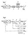
- FIG. 5 An OFDM sander, that is to say its coding or modulation device CM, is fed with a bit sequence. This is followed by the usual processing with IFFT (Inverse Fast Fourier Transformation), parallel-serial conversion P / S and the insertion of the guard interval SI by periodic continuation (compare [1]). Subsequently, at the beginning of each transmission, the synchronization sequence is read from a memory SP and, together with the preamble, after FIG. 4 inserted by means of the insertion device EB. The signal is converted digitally-analogue (D / A) and transferred to the transmission front end SF, where it is possibly mixed up into another frequency position and transmitted via an antenna.
- D / A digitally-analogue
- the insertion of the synchronization sequence is done in the realization in FIG. 5 after the IFFT, so that in the memory SP, the time signal of the synchronization sequence must be present. But under certain conditions it is it is also possible to insert the synchronization sequence before the IFFT and have it processed by the IFFT.
- the mixed into the base fire and converted analog-digital signal enters a sample memory AS.
- the synchronization device SY can access this sampling memory AS in order to carry out the block synchronization, frequency synchronization and channel estimation.
- a windowing unit BS is addressed which reads the correct values from the sample buffer memory.
- a frequency correction is performed in the mixing device FS with the determined frequency offset.
- the channel parameters determined by the channel estimation are used for demodulation and decoration DM.
- the presented method assumes that the different signal sequences each have the same length.
Claims (15)
- Procédé de synchronisation d'un ou plusieurs récepteurs par rapport à un émetteur dans un système de transmission par recours à un flux de données doté d'intervalles de protection, le procédé présentant les étapes suivantes :- en particulier au début de l'émission, l'émetteur (S) insère dans le flux de données une succession spéciale de synchronisation qui permet en particulier d'estimer la position temporelle du signal à recevoir et/ou le décalage de fréquence entre l'émetteur (S) et les récepteurs (E),- la succession de synchronisation est formée d'au moins deux séquences de symboles différentes (A, B) qui sont émises périodiquement en alternance,- la position temporelle du signal à recevoir et/ou le décalage de fréquence entre l'émetteur (S) et le récepteur (E) sont déterminés à partir d'un terme qui associée les différentes séquences de symboles (A, B) à l'intérieur d'un intervalle prédéterminé,- pour obtenir une synchronisation par blocs, la métrique totale des deux ou plusieurs séquences différentes de symboles utilisées comme succession de synchronisation est prise en compte et l'index qui minimise la métrique totale à l'intérieur d'un intervalle prédéterminé est sélectionné comme début du bloc.
- Procédé selon la revendication 1, caractérisé en ce que dans un système de transmission OFDM, les séquences de symboles (A, B) sont constituées de symboles OFDM qui ont une longueur identique à celle d'un symbole de données habituel ou différente de celle-ci.
- Procédé selon les revendications 1 ou 2, caractérisé en ce que les séquences de symboles (A, B) sont émises au moins par paires et en alternance.
- Procédé selon les revendications 1 ou 2, caractérisé en ce que lorsqu'il y a plus de deux séquences de symboles différentes, au moins une séquence de symboles est rassemblée sous la forme d'une paire située à distance d'au moins une autre paire d'une autre séquence de symboles pour former la succession de synchronisation.
- Procédé selon les revendications 3 ou 4, caractérisé en ce que des intervalles de protection sont prévus entre les différentes paires de séquences de symboles (AA, BB, AA, ...).
- Procédé selon l'une des revendications 1 à 5, caractérisé en ce que dans une synchronisation par blocs, la métrique totale des séquences de symboles utilisée comme succession de synchronisation est prise en compte et l'index qui minimise la métrique totale à l'intérieur de l'intervalle prédéterminé est sélectionné comme début de bloc.
- Procédé selon l'une des revendications 1 à 6, caractérisé en ce que l'intervalle prédéterminé est défini par la structure de trame du flux de données.
- Procédé selon l'une des revendications 1 à 7, caractérisé en ce que l'angle de phase entre deux parties identiques voisines du signal est déterminé pour estimer le décalage de fréquence.
- Procédé selon la revendication 8, caractérisé en ce que les angles de phase entre d'autres parties identiques de signal sont également déterminés et en ce que le décalage total en fréquence est estimé par formation de la moyenne des angles de phase ainsi déterminés.
- Procédé selon l'une des revendications 1 à 9, caractérisé en ce que les séquences de symboles pour l'estimation des canaux sont utilisées pour une démodulation cohérente en faisant subir à la séquence de symboles une transformation rapide de Fourier (FFT) après correction de la fréquence dans le récepteur et en ce que les amplitudes et pondérations de phase des différentes sous-porteuses sont déterminées.
- Procédé selon la revendication 10, caractérisé en ce que les paramètres des canaux sont estimés par formation d'une valeur moyenne sur les différentes séquences de symboles (A, B).
- Procédé selon l'une des revendications 1 à 11, caractérisé en ce que la succession de synchronisation est précédée d'un préambule (P) prévu en particulier pour régler la régulation d'amplitude (GC) du récepteur (E).
- Système de communication doté d'un émetteur (S) qui prépare une succession de synchronisation pour au moins un récepteur (E) en vue d'évaluer la succession de synchronisation à l'intérieur d'un système de transmission par recours à un flux de données doté d'intervalles de protection, en particulier pour la compensation de la propagation multiparcours, avec les caractéristiques suivantes du côté de l'émetteur :- un dispositif numérique de codage et de modulation (CM) de symboles d'émission sur plusieurs sous-porteuses dans la plage de fréquences,- un dispositif (EB) d'insertion d'une succession de synchronisation formée d'au moins deux séquences de symboles différentes (A, B), le dispositif d'insertion (EB) étant configuré de manière à pouvoir réaliser une insertion périodique alternée de la succession de synchronisation dans le flux de données préparé par le dispositif de codage et de modulation (CM),- un dispositif de mémoire (SP) pour les différentes séquences de symboles et leur association, qui coopère avec le dispositif d'insertion (EB),
ainsi que les caractéristiques suivantes du côté du récepteur :- une mémoire d'échantillonnage (AS) d'un flux de données reçu,- un dispositif (SY) d'évaluation de synchronisation qui coopère avec la mémoire d'échantillonnage (AS) et qui permet d'évaluer la position temporelle et/ou le décalage de fréquence à l'intérieur d'un intervalle prédéterminé d'une succession de synchronisation constituée d'au moins deux séquences de symboles différentes (A, B) qui peuvent être émises périodiquement et en alternance par l'émetteur (S) et de commander des unités correspondantes de réception pour la synchronisation des blocs (BS), la synchronisation en fréquence dans un dispositif de mixage (FS) et/ou l'estimation des canaux (KS) pour la démodulation et le décodage (DM). - Système de communication selon la revendication 13, configuré comme système de communication radio, système de communication par fil ou système de communication hybride, c'est-à-dire système de communication présentant des composantes radio, des composantes à conducteurs d'ondes lumineuses et/ou des composantes filaires, et dans lequel des émetteurs (S) et des récepteurs (E) travaillent en fonctionnant en émission ou en réception de manière variable.
- Système de communication bidirectionnelle selon la revendication 13, configuré comme système de communication radio, système de communication filaire ou système de communication hybride, c'est-à-dire système de communication présentant des composantes radio, des composantes à conducteurs d'ondes lumineuses et/ou des composantes filaires, dans lequel l'attribution du fonctionnement en émission ou en réception aux émetteurs (S) et aux récepteurs (E) est prédéterminée de manière fixe.
Applications Claiming Priority (3)
| Application Number | Priority Date | Filing Date | Title |
|---|---|---|---|
| DE19914600A DE19914600A1 (de) | 1999-03-30 | 1999-03-30 | Verfahren zur Synchronisation |
| DE19914600 | 1999-03-30 | ||
| PCT/DE2000/000915 WO2000060805A2 (fr) | 1999-03-30 | 2000-03-28 | Procede de synchronisation |
Publications (2)
| Publication Number | Publication Date |
|---|---|
| EP1166516A2 EP1166516A2 (fr) | 2002-01-02 |
| EP1166516B1 true EP1166516B1 (fr) | 2010-03-17 |
Family
ID=7903074
Family Applications (1)
| Application Number | Title | Priority Date | Filing Date |
|---|---|---|---|
| EP00929244A Expired - Lifetime EP1166516B1 (fr) | 1999-03-30 | 2000-03-28 | Procede de synchronisation |
Country Status (6)
| Country | Link |
|---|---|
| US (1) | US7170884B1 (fr) |
| EP (1) | EP1166516B1 (fr) |
| JP (1) | JP4582609B2 (fr) |
| KR (1) | KR100738826B1 (fr) |
| DE (2) | DE19914600A1 (fr) |
| WO (1) | WO2000060805A2 (fr) |
Families Citing this family (13)
| Publication number | Priority date | Publication date | Assignee | Title |
|---|---|---|---|---|
| JP2002204215A (ja) * | 2000-12-28 | 2002-07-19 | Kddi Research & Development Laboratories Inc | Ofdm受信装置の位相誤差補正装置 |
| KR100726964B1 (ko) * | 2002-04-15 | 2007-06-14 | 삼성탈레스 주식회사 | 직교 주파수 분할 다중 송수신기 심벌 프레임 동기화 장치및 방법 |
| US7505522B1 (en) | 2003-10-06 | 2009-03-17 | Staccato Communications, Inc. | Spectral shaping in multiband OFDM transmitter with clipping |
| DE112004001837D2 (de) * | 2003-10-18 | 2006-06-08 | Univ Dresden Tech | Verfahren zur Synchronisation bei der Übertragung von OFDM-Signalen |
| EP3267215B1 (fr) | 2004-02-23 | 2023-08-09 | Intellectual Ventures Holding 81 LLC | Systèmes et procédés de mise en uvre d'une architecture en boucle ouverte dans un réseau de communication sans fil |
| US7477683B2 (en) | 2004-03-29 | 2009-01-13 | Stmicroelectronics Ltd. | Periodic DMT signals with cyclic extension |
| US7519123B1 (en) | 2004-04-08 | 2009-04-14 | Staccato Communications, Inc. | Spectral shaping for multiband OFDM transmitters with time spreading |
| JP4264550B2 (ja) * | 2005-11-15 | 2009-05-20 | ソニー株式会社 | 受信装置並びにチャネル推定装置 |
| US20080107011A1 (en) * | 2006-11-02 | 2008-05-08 | Mediatek Inc. | System, Apparatus, and Method for Processing a Received Orthogonal Frequency Division Multiplexing Signal |
| KR101244247B1 (ko) | 2011-11-18 | 2013-03-18 | 국방과학연구소 | 프레임-반송파 결합 동기 장치 및 동기 방법 |
| US9590411B2 (en) | 2011-12-15 | 2017-03-07 | Schweitzer Engineering Laboratories, Inc. | Systems and methods for time synchronization of IEDs via radio link |
| US9599719B2 (en) | 2012-10-19 | 2017-03-21 | Schweitzer Engineering Laboratories, Inc. | Detection of manipulated satellite time signals |
| AU2013331048A1 (en) | 2012-10-19 | 2015-04-09 | Schweitzer Engineering Laboratories, Inc. | Time distribution switch |
Family Cites Families (11)
| Publication number | Priority date | Publication date | Assignee | Title |
|---|---|---|---|---|
| JPS6022726B2 (ja) | 1978-06-13 | 1985-06-04 | 株式会社ボッシュオートモーティブ システム | 変位検出器 |
| DE4128713A1 (de) * | 1991-08-29 | 1993-03-04 | Daimler Benz Ag | Verfahren und anordnung zur messung der traegerfrequenzablage in einem mehrkanaluebertragungssystem |
| FR2691534B1 (fr) | 1992-05-19 | 1994-08-26 | Moving Magnet Tech | Capteur de position à aimant permanent et sonde de hall. |
| US5372113A (en) * | 1994-01-25 | 1994-12-13 | Siemens Automotive L.P. | Weir control of fuel level in a fuel rail tube for reducing the risk of hydra-lock |
| SE514809C2 (sv) * | 1994-07-13 | 2001-04-30 | Hd Divine Ab | Metod och anordning för synkronisering av sändare och mottagare i digitalt system |
| US5809083A (en) * | 1994-11-23 | 1998-09-15 | At&T Wireless Services, Inc. | Differentially encoded pilot word system and method for wireless transmissions of digital data |
| DE4446639B4 (de) * | 1994-12-24 | 2004-04-29 | Rohde & Schwarz Gmbh & Co. Kg | Verfahren zur Gewinnung einer Schätzung von Trägerfrequenz und Trägerphase eines nach einem kohärenten mehrstufigen Modulationsverfahren modulierten Funksignals zu dessen Demodulation in einem Empfänger |
| US5732113A (en) * | 1996-06-20 | 1998-03-24 | Stanford University | Timing and frequency synchronization of OFDM signals |
| DE19738316A1 (de) | 1997-09-02 | 1999-03-04 | Itt Mfg Enterprises Inc | Berührungsloser Wegmesser insbesondere zur Verschleißmessung von Bremsklötzen |
| JP3576412B2 (ja) * | 1998-12-22 | 2004-10-13 | 株式会社東芝 | Ofdm信号伝送方法、ofdm信号送信装置及びofdm信号受信装置 |
| US6654429B1 (en) * | 1998-12-31 | 2003-11-25 | At&T Corp. | Pilot-aided channel estimation for OFDM in wireless systems |
-
1999
- 1999-03-30 DE DE19914600A patent/DE19914600A1/de not_active Ceased
-
2000
- 2000-03-28 DE DE50015890T patent/DE50015890D1/de not_active Expired - Lifetime
- 2000-03-28 EP EP00929244A patent/EP1166516B1/fr not_active Expired - Lifetime
- 2000-03-28 WO PCT/DE2000/000915 patent/WO2000060805A2/fr active Application Filing
- 2000-03-28 US US09/937,608 patent/US7170884B1/en not_active Expired - Fee Related
- 2000-03-28 JP JP2000610177A patent/JP4582609B2/ja not_active Expired - Fee Related
- 2000-03-28 KR KR1020017012425A patent/KR100738826B1/ko not_active IP Right Cessation
Also Published As
| Publication number | Publication date |
|---|---|
| JP2002541729A (ja) | 2002-12-03 |
| DE50015890D1 (de) | 2010-04-29 |
| WO2000060805A2 (fr) | 2000-10-12 |
| US7170884B1 (en) | 2007-01-30 |
| KR100738826B1 (ko) | 2007-07-13 |
| DE19914600A1 (de) | 2000-10-05 |
| JP4582609B2 (ja) | 2010-11-17 |
| WO2000060805A3 (fr) | 2001-01-11 |
| KR20020003225A (ko) | 2002-01-10 |
| EP1166516A2 (fr) | 2002-01-02 |
Similar Documents
| Publication | Publication Date | Title |
|---|---|---|
| DE60027432T2 (de) | Synchronisierung sowie erfassung der modulationsart | |
| DE69728383T2 (de) | Verfahren und Apparat für Zeitsynchronisierung in einem Empfänger für ein Mehrträgersignal | |
| EP1779624B1 (fr) | Procede pour produire des structures de preambule et de signalisation dans un systeme de transmission mimo-ofdm | |
| DE102008010126B4 (de) | System mit einem OFDM-Kanalschätzer | |
| DE69924804T2 (de) | Ofdm (orthogonale frequenzmultiplexierung)-empfänger | |
| DE102004052899B4 (de) | Sowohl auf sporadische als auch auf kontinuierliche Datenkommunikation ausgerichtetes OFDM-Übertragungsverfahren für ein WLAN | |
| EP1374513B1 (fr) | Procede de synchronisation de trame et de frequence de signaux ofdm et procede d'emission de signaux ofdm | |
| EP1166516B1 (fr) | Procede de synchronisation | |
| DE69933409T2 (de) | Verfahren un Anordnung zum Erreichen und Aufrechterhalten der Symbolsynchronisierung in einem OFDM-Übertragungssystem | |
| DE69830952T2 (de) | Verfahren und System zur Bestimmung des Symbolübertragungsformats in einem Übertragungssystem | |
| DE69736659T2 (de) | Mehrträgerempfänger mit Ausgleich von Frequenzverschiebungen und von frequenzabhängigen Verzerrungen | |
| EP0196723A2 (fr) | Méthode et circuit pour la synchronisation des dispositifs de réception dans un système de transmission multiplex numérique | |
| EP3610617B1 (fr) | Récepteur et émetteur et procédés correspondants | |
| DE10026325B4 (de) | Verfahren zur Synchronisation von OFDM-Symbolen bei Rundfunkübertragungen | |
| EP0454266A2 (fr) | Récepteur comprenant un circuit pour estimer l'écart de fréquence | |
| DE602004012381T2 (de) | Verfahren zur zeit- und frequenzbereichssynchronisation mehrerer einrichtungen in einem übertragungssystem mit ofdm-modulation | |
| DE19925925B4 (de) | Verfahren zur Übertragung von Funksignalen und Empfänger zum Empfang von Funksignalen | |
| EP0534399A2 (fr) | Procédé de multiplexage temporel pour déterminer la variation de phase d'un signal de réception | |
| DE69824898T2 (de) | Schätzung der kanalimpulsantwort mittels der streuung vom empfangenen signal | |
| DE60219474T2 (de) | Frequenzkorrektion für ein mehrträgersystem | |
| EP1643707B1 (fr) | Méthode pour la synchronisation d'une horloge d'échantillonnage et ensemble de synchronisation pour un système récepteur multiporteuse | |
| DE102021114327B3 (de) | Verfahren zur Übertragung von Signalen zwischen mehreren Sendern und mehreren Empfängern eines drahtlosen Kommunikationsnetzes | |
| EP2206305B1 (fr) | Synchronisation de symboles recus pour ofdm | |
| EP1023790A1 (fr) | Procede et station radio pour transmettre des donnees | |
| DE102005035203B4 (de) | Verfahren zum Schätzen einer Kanalimpulsantwort eines Funkkanals sowie Funkstation |
Legal Events
| Date | Code | Title | Description |
|---|---|---|---|
| PUAI | Public reference made under article 153(3) epc to a published international application that has entered the european phase |
Free format text: ORIGINAL CODE: 0009012 |
|
| 17P | Request for examination filed |
Effective date: 20011030 |
|
| AK | Designated contracting states |
Kind code of ref document: A2 Designated state(s): AT BE CH CY DE DK ES FI FR GB GR IE IT LI LU MC NL PT SE |
|
| RBV | Designated contracting states (corrected) |
Designated state(s): DE FI FR GB SE |
|
| 17Q | First examination report despatched |
Effective date: 20070822 |
|
| GRAP | Despatch of communication of intention to grant a patent |
Free format text: ORIGINAL CODE: EPIDOSNIGR1 |
|
| GRAS | Grant fee paid |
Free format text: ORIGINAL CODE: EPIDOSNIGR3 |
|
| GRAA | (expected) grant |
Free format text: ORIGINAL CODE: 0009210 |
|
| AK | Designated contracting states |
Kind code of ref document: B1 Designated state(s): DE FI FR GB SE |
|
| REG | Reference to a national code |
Ref country code: GB Ref legal event code: FG4D Free format text: NOT ENGLISH |
|
| REF | Corresponds to: |
Ref document number: 50015890 Country of ref document: DE Date of ref document: 20100429 Kind code of ref document: P |
|
| PG25 | Lapsed in a contracting state [announced via postgrant information from national office to epo] |
Ref country code: FI Free format text: LAPSE BECAUSE OF FAILURE TO SUBMIT A TRANSLATION OF THE DESCRIPTION OR TO PAY THE FEE WITHIN THE PRESCRIBED TIME-LIMIT Effective date: 20100317 |
|
| PG25 | Lapsed in a contracting state [announced via postgrant information from national office to epo] |
Ref country code: SE Free format text: LAPSE BECAUSE OF FAILURE TO SUBMIT A TRANSLATION OF THE DESCRIPTION OR TO PAY THE FEE WITHIN THE PRESCRIBED TIME-LIMIT Effective date: 20100317 |
|
| PLBE | No opposition filed within time limit |
Free format text: ORIGINAL CODE: 0009261 |
|
| STAA | Information on the status of an ep patent application or granted ep patent |
Free format text: STATUS: NO OPPOSITION FILED WITHIN TIME LIMIT |
|
| 26N | No opposition filed |
Effective date: 20101220 |
|
| PGFP | Annual fee paid to national office [announced via postgrant information from national office to epo] |
Ref country code: FR Payment date: 20110401 Year of fee payment: 12 |
|
| PGFP | Annual fee paid to national office [announced via postgrant information from national office to epo] |
Ref country code: GB Payment date: 20110324 Year of fee payment: 12 |
|
| PGFP | Annual fee paid to national office [announced via postgrant information from national office to epo] |
Ref country code: DE Payment date: 20110525 Year of fee payment: 12 |
|
| GBPC | Gb: european patent ceased through non-payment of renewal fee |
Effective date: 20120328 |
|
| REG | Reference to a national code |
Ref country code: FR Ref legal event code: ST Effective date: 20121130 |
|
| REG | Reference to a national code |
Ref country code: DE Ref legal event code: R119 Ref document number: 50015890 Country of ref document: DE Effective date: 20121002 |
|
| PG25 | Lapsed in a contracting state [announced via postgrant information from national office to epo] |
Ref country code: FR Free format text: LAPSE BECAUSE OF NON-PAYMENT OF DUE FEES Effective date: 20120402 Ref country code: GB Free format text: LAPSE BECAUSE OF NON-PAYMENT OF DUE FEES Effective date: 20120328 |
|
| PG25 | Lapsed in a contracting state [announced via postgrant information from national office to epo] |
Ref country code: DE Free format text: LAPSE BECAUSE OF NON-PAYMENT OF DUE FEES Effective date: 20121002 |