EP1166492B1 - Duty cycle corrector for a random number generator - Google Patents
Duty cycle corrector for a random number generatorInfo
- Publication number
- EP1166492B1 EP1166492B1 EP00930090A EP00930090A EP1166492B1 EP 1166492 B1 EP1166492 B1 EP 1166492B1 EP 00930090 A EP00930090 A EP 00930090A EP 00930090 A EP00930090 A EP 00930090A EP 1166492 B1 EP1166492 B1 EP 1166492B1
- Authority
- EP
- European Patent Office
- Prior art keywords
- bits
- bit
- circuit
- output
- duty cycle
- Prior art date
- Legal status (The legal status is an assumption and is not a legal conclusion. Google has not performed a legal analysis and makes no representation as to the accuracy of the status listed.)
- Expired - Lifetime
Links
Images


Classifications
-
- H—ELECTRICITY
- H04—ELECTRIC COMMUNICATION TECHNIQUE
- H04L—TRANSMISSION OF DIGITAL INFORMATION, e.g. TELEGRAPHIC COMMUNICATION
- H04L9/00—Cryptographic mechanisms or cryptographic arrangements for secret or secure communications; Network security protocols
- H04L9/06—Cryptographic mechanisms or cryptographic arrangements for secret or secure communications; Network security protocols the encryption apparatus using shift registers or memories for block-wise or stream coding, e.g. DES systems or RC4; Hash functions; Pseudorandom sequence generators
- H04L9/065—Encryption by serially and continuously modifying data stream elements, e.g. stream cipher systems, RC4, SEAL or A5/3
- H04L9/0656—Pseudorandom key sequence combined element-for-element with data sequence, e.g. one-time-pad [OTP] or Vernam's cipher
- H04L9/0662—Pseudorandom key sequence combined element-for-element with data sequence, e.g. one-time-pad [OTP] or Vernam's cipher with particular pseudorandom sequence generator
-
- H—ELECTRICITY
- H04—ELECTRIC COMMUNICATION TECHNIQUE
- H04L—TRANSMISSION OF DIGITAL INFORMATION, e.g. TELEGRAPHIC COMMUNICATION
- H04L2209/00—Additional information or applications relating to cryptographic mechanisms or cryptographic arrangements for secret or secure communication H04L9/00
- H04L2209/12—Details relating to cryptographic hardware or logic circuitry
Definitions
- the present invention relates generally to computer security, and more specifically to generating an approximately uniform duty cycle in a random number generator.
- Random number generator circuits are used in a variety of electronic applications.
- One important application for random number generators is in the field of computer security where message data is encrypted and decrypted.
- Cryptography involves the transformation of data into a coded message that is to be sent to and decoded only by the intended recipient.
- Most common cryptographic techniques use ciphers (or "keys") used by the sender to encode the message and by the receiver to decode the encoded message.
- Common cipher systems use either a single key, one to code and decode a message, or two keys, one to encode the message and the other to decode the message.
- the keys used to encode and decode messages are basically binary data patterns against which a message is processed or filtered.
- Effective cipher systems require the use of keys that have a sufficiently high number of bits to make replication of a key nearly impossible.
- the data patterns comprising the keys must be sufficiently random so that their pattern or the patterns in the message encoded by the key cannot be predicted.
- Effective cryptographic systems thus require the use of high quality random number generators to ensure that the binary data within a message is transformed in a totally unpredictable manner.
- any lack of randomness in an encryption scheme produces some degree of correlation between the coded and uncoded data. This correlation can then be used crack the code through techniques such as iterative trial and error predictions of possible output patterns based on a coded message.
- a desirable feature of a binary random number generator is that it output one and zero bits in a purely random order. Thus, the value of the output bit at any given time should be totally unpredictable. It is desirable that the duty cycle of the output of the random number generator be approximately fifty percent over an infinite sample size, so that the chance of an output being a logic low (zero) is equal to the chance of the output being a logic high (one). It is also desirable for a random number generator to exhibit low correlation (e.g., approximately zero correlation) between any bit and any other bit, and a flat Fourier distribution among the output bits.
- US-A-5781458 discloses an apparatus for generating random numbers for use in a cryptographic key generator.
- the apparatus extracts entropy from the output signal of an RC oscillating circuit by comparing the period of a first signal with the period of a second signal where the first and second periods are separated by two cycles. If the periods are equal then data is discarded. If the previous period is greater than the later period, a "1" is assigned to a shift register, otherwise, a "0" is assigned to the shift register.
- Such an apparatus is unable to produce a uniform duty cycle output of 1's and 0's, as is a desired object of the present invention.
- Figure 1 illustrates an example of a prior art random number generator that uses a Linear Feedback Shift Register 104 coupled to the output of a random bit source 102
- LFSR 104 comprises a number of latches 105 and gates 106 through which the output bits from random bit source 102 are propagated.
- the states of the output bits are randomly inverted by gates 106, and the order of the bits is further mixed up through feed-back of the bits through latches 105.
- Linear Feedback Shift Registers such as that illustrated in Figure 1 possess certain disadvantages and do not fully correct non-level duty cycle characteristics exhibited by typical random bit sources.
- LFSR 104 a typical LFSR itself comprises a number of latches and gates. These latches and gates will tend to exhibit the same propensity to latch a zero or one in certain circumstances, as the latches in the random bit source 102. Therefore, a typical LFSR does not itself produce a uniform duty cycle output of ones and zeros, and thus cannot entirely correct any duty cycle variations in a random bit source.
- Linear Feedback Shift Registers A further disadvantage of Linear Feedback Shift Registers is the requirement of a large number of latches and gates.
- a 32-bit LFSR such as shown in Figure 1, requires 32 D-type latches, as well as a number of combinatorial gates. This adds significantly to the amount of silicon area required for a random number generator circuit that uses such an LFSR.
- a duty cycle corrector for use in a random number generator is described.
- sequential pairs of bits output from the random bit source are processed by the duty cycle corrector. If both bits in a pair of bits are identical, the duty cycle corrector discards or does not output the pair of bits. If the bits in a pair of bits are different, the duty cycle corrector outputs one of the bits in the bit pair.
- a random bit source is a digital circuit that outputs a series of binary digits in a presumably random order.
- the probability that a given output bit will be a zero is equal to the probability that it will be a one. That is, the duty cycle of the output waveform of the random bit source will be uniformly fifty percent over a statistically significant sample size.
- most random bit sources exhibit some variation in duty cycle due to a tendency of latches and gates within random bit source to latch to a particular logic level when data is latched during a forbidden hold or setup time.
- this property is true regardless of the probability of the random bit source producing a one or zero for any given output. Thus, even if p does not equal 50 percent for a particular random bit source, the probability that the random bit source will produce a zero-one output pair is equal to the probability that it will produce a one-zero output pair. In one embodiment of the present invention, this principle is used to correct the output of a random bit source that exhibits a nonuniform duty cycle and generates an unequal distribution of zeros and ones in a given output bit stream.
- a duty cycle corrector processes bit pairs output from a random bit source to determine a corrected, substantially uniform bit stream. In one embodiment, if both bits in a pair of bits are identical, then that pair is discarded and not output by the duty cycle corrector as part of the corrected bit stream. Thus, if both bits in a pair of output bits are zero, this pair is discarded. Likewise, if both bits in a pair of output bits are one, this pair is discarded. If, however, the bits in a pair of output bits are different, the duty cycle corrector outputs one of the bits in the pair as a bit in the corrected bit stream. In one embodiment, the duty cycle corrector outputs the first bit in a dissimilar pair of bits as the corrected bit.
- the corrected bit is set to zero; and if the output pair is one-zero, the corrected bit is set to one.
- the duty cycle corrector outputs the second bit in a dissimilar pair of bits as the correct bit.
- the corrected bit is set to one; and if the output pair is one-zero, the corrected bit is set to zero.
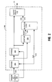
- Figure 2 shows one embodiment of a duty cycle corrector 200 that implements the embodiments described above to produce a substantially uniform bit stream from a random bit source 202 while using fewer gates than previous LFSR circuits.
- Random bit source 202 may be any random bit source that outputs a random stream of bits to signal line 222.
- random bit source 202 is implemented as a latch circuit that uses a randomly varying low speed clock signal to periodically latch a high speed oscillating signal. The value of the output bit from the random bit source latch depends on the voltage level of the high speed signal when it is latched by the low speed signal.
- Random bit source 202 may also generate a clock or strobe signal CLK on signal line 216 as generally known in the art.
- Duty cycle corrector 200 includes storage elements 204 and 206, compare circuit 208, validation logic 210, and an output circuit 212.
- Storage circuits 204 and 206 store pairs of successive bits in the random bit stream output from random bit source 202 for comparison by compare circuit 208. In a first clock cycle of CLK, the first bit in a pair of bits is stored in storage circuit 204. In a later clock cycle, the first bit is stored in storage circuit 206 while the next bit output from random bit source 202 is stored in storage circuit 204.
- Storage circuits 204 and 206 may be any type of storage elements including latches, registers, volatile or non-volatile memory cells, and the like.
- Compare circuit 208 may be any type of compare circuit including an XOR gate or a comparator. If both bits are equal, compare circuit 208 asserts the ACCEPT signal on signal line 220 to a high logic state. If both bits are not equal, however, compare circuit 208 deasserts the ACCEPT signal to a low logic state. Thus, the ACCEPT signal indicates whether the pair of bits output from the random bit source will generate a corrected bit in the bit stream output by duty cycle corrector 200.
- the ACCEPT signal is provided to validation logic 210 together with CLK. Compare circuit 208 will assert ACCEPT when any two successive bits in storage circuits 204 and 206 are different bits. It is advantageous, however, to compare non-overlapping pairs of bits output from random bit source 202 in order to produce a uniform duty cycle output stream from duty cycle corrector 200. Validation logic 210 performs this function. Validation logic 210 asserts the strobe signal STB to a high logic state on signal line 218 when ACCEPT is asserted and the desired bit pair is stored in storage circuits 204 and 206. When STB is asserted, output circuit 212 stores the bit in storage circuit 206.
- Output circuit 212 may be any storage element including a register, a latch, one or more volatile or nonvolatile memory elements, an AND gate, or other logic.
- the bit stored by output circuit 212 is output to signal line 214 as the corrected bit corresponding to the bits stored in storage circuits 204 and 206.
- the output storage circuit 204 may be provided to output circuit 212 instead of the output of storage circuit 206.
- output circuit 212 when STB is asserted, stores the bit in storage circuit 204, and outputs this bit as the corrected bit corresponding to the bits stored in storage circuits 204 and 206.
- Duty cycle corrector 300 that is one embodiment of duty cycle corrector 200.
- Duty cycle corrector 300 includes latches 304 and 306 that are one embodiment of storage circuits 204 and 206, respectively; XOR gate 310 that is one embodiment of compare circuit 210; transparent latch 308 and AND gate 309 that together comprise one embodiment of validation logic 210; and latch 312 that is one embodiment of output circuit 212.
- Latches 304 and 306 latch pairs of successive bits from random bit source 202 for comparison by XOR gate 310.
- the first bit in a pair of bits is latched in latch 304 by CLK. On the next clock pulse of CLK, this first bit is latched in latch 306, and the next bit output from random bit source 202 is latched in latch 304. If both bits in a bit pair are equal, XOR gate 310 deasserts ACCEPT to a zero; if both bits in a bit pair are not equal, XOR gate 310 asserts ACCEPT to a one.
- Transparent latch 308 latches CLK from random bit source 302 for clocking the AND gate 309 such that STB will be asserted only when ACCEPT is asserted and a non-overlapping bit pair is stored in latches 304 and 306.
- latch 312 latches the bit output from latch 306 as the corrected bit output on signal line 214.
- the output of latch 304 may be provided to latch 312. This bit may be latched by latch 312 in response to STB.
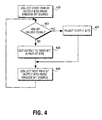
- FIG. 4 is a flowchart that illustrates the operation of duty cycle corrector 300.
- a first pair of bits from random bit source 202 are latched into latches 304 and 306 with the first bit stored in latch 306 and the second bit stored in latch 304.
- XOR gate 310 determines if the two bits of the pair are equal. If the pair of bits are equal at step 204, ACCEPT is deasserted, STB is deasserted, and the bit pair is rejected or discarded. At step 204, neither bit is latched by latch 312 and output to signal line 214. If, however, the two bits are determined to be different from one another at step 402, the first bit is taken as the output bit at step 406.
- step 408 the next overlapping pair of bits from random bit source 202 are collected, and the process repeats from step 402. This process repeats until all output bit pairs from the random bit source have been processed. Any output bits from the random number source that are unpaired cannot be processed and are thus rejected. It should be noted that although the first bit of the pair from latch 306 is supplied as the corrected bit, in an alternative method, the second bit of the pair from latch 304 is supplied as the corrected bit.
- FIG. 5 shows that the second bit pair (bits 2 and 3) and the third bit pairs (bits 4 and 5) generate corrected bits, while the first bit pair (bits 0 and 1) and the fourth bit pair (bits 6 and 7) do not.
- Random bit source 202 may output bits that have a first order autocorrelation between successively generated bits due to the nature of latches, logic gates, and other circuit elements.
- a duty cycle corrector such as those shown above in Figures 2 and 3 may be able to output substantially a random bit pattern having a substantially uniform duty cycle, the likelihood that the output of the duty cycle corrector is closer to a uniform duty cycle increases if the autocorrelation between bits output by the random bit source is lower. That is, the likelihood that the output of the duty cycle corrector is closer to a uniform duty cycle increases if the bits in the random bit stream are unrelated to each other.
- duty cycle corrector 300 of Figure 3 may be affected by first order autocorrelation between the bits in the random bit stream output by random bit source 202 as duty cycle corrector 300 operates on consecutive bit pairs.
- Figures 6 shows another embodiment of a duty cycle corrector 600 that reduces the affect of first order autocorrelation between bits pairs output by random bit source 202. Duty cycle corrector 600 reduces first order autocorrelation by discarding a bit from random bit source 202 once a bit pair is detected that generates a corrected bit.
- Duty cycle corrector 600 is similar to duty cycle corrector 300, except that transparent latch 308 of the validation logic has been replaced with modulo-2 counter 602.
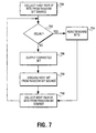
- the operation of duty cycle corrector 600 is illustrated in Figure 7.
- a first pair of bits from random bit source 202 are latched into latches 304 and 306 on counts 0 and 1 of modulo-2 counter 602.
- XOR gate 310 determines if the two bits of the pair are equal. If the pair of bits are equal at step 704, ACCEPT is deasserted, STB is deasserted, and the bit pair is rejected or discarded.
- neither bit is latched by latch 312 and output to signal line 214.
- step 704 ACCEPT is asserted on count 1, STB is asserted, and the first bit (or, alternatively, the second bit) is output by output by latch 312. STB is also fed back to modulo-2 counter 602 such that when STB is asserted modulo-2 counter 602 skips a count and holds the next two clock cycles low (i.e., both count 0). This will cause, at step 807, duty cycle corrector 600 to discard the next bit in the random bit stream from random bit source 202. This occurs because even though the next bit is loaded into latch 304, it will be clocked through latch 306 before the next time that modulo-2 counter 602 will output count 1 to AND gate 309.
- step 708 the next overlapping pair of bits from random bit source 202 are collected, and the process repeats from step 702. This process repeats until all output bit pairs from the random bit source have been processed.
- duty cycle corrector 600 When the first bit pair (bits 0 and 1) are equal, the bits are discarded and no corrected bit is generated for this bit pair. Additionally, STB will not be asserted and modulo-2 counter 602 will not skip a count. The second bit pair (bits 2 and 3) are not equal and duty cycle corrector 600 outputs a zero, and then causes the next bit, bit 4, to be discarded because modulo-2 counter 602 skips a count. The third bit pair (bits 5 and 6) are also not equal. Duty cycle corrector 600 outputs a one and causes the next bit, bit 7, to be discarded because modulo-2 counter 602 skips a count. The last bit pair (bits 8 and 9) are equal and are discarded.
- bits 4 and 7 will reduce the first order autocorrelation between the second bit pair (bits 2 and 3) and the third bit pair (bits 5 and 6), and between the third bit pair and the fourth bit pair (bits 8 and 9).
- the corrected bit stream will be influenced by a less significant second order autocorrelation between the second bit pair and the third bit pair, and between the third bit pair and the fourth bit pair output by random bit source 202.
- Duty cycle corrector 600 reduces the first order autocorrelation between bits generated by the random bit source. It may, however, tend to introduce a nonuniformity in the duty cycle of the corrected bit stream as the singular discarded bits (e.g., bits 4 and 7 of Figure 8) may not be evenly distributed in the random bit stream.
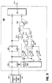
- FIG. 9 shows another embodiment of a duty cycle corrector 900 that reduces the affect of first order autocorrelation between bits pairs output by random bit source 202.
- Duty cycle corrector 900 reduces first order autocorrelation by discarding bits from random bit source 202 that are shifted in on particular counts of a modulo-5 counter.
- Duty cycle corrector 900 is similar to duty cycle corrector 300, except that transparent latch 308 of the validation logic has been replaced with modulo-5 counter 902, inverters 904, 906, and 908, AND gates 910 and 912, and NOR gate 914.
- Modulo-5 counter 902 has three binary output bits C0, C1, and C2.
- AND gate 910 is a three-input AND gate that has a first input coupled C2 via inverter 904, a second input coupled to C1, and a third input coupled to C0 via inverter 908.
- AND gate 912 is a three-input AND gate that has a first input coupled to C2, a second input coupled to C1 via inverter 906, and a third input coupled to C0 via inverter 908.
- NOR gate 914 receives the outputs of AND gates 910 and 912, and drives one input of AND gate 309.
- duty cycle corrector 900 The operation of duty cycle corrector 900 is illustrated in Figure 10.
- a first bit is loaded into latch 304. This bit will be discarded because the signal on signal line 915 will not be asserted for counts 0 and 1.
- a first pair of bits from random bit source 202 is latched into latches 304 and 306 on counts 1 and 2. This will cause the first bit to be discarded from corrector 1000.
- XOR gate 310 determines if the two bits of the pair are equal. If the pair of bits are equal, then at step 1006 ACCEPT is deasserted, STB is deasserted, and the bit pair is rejected or discarded.
- neither bit is latched by latch 312 and output to signal line 214. If the bits do not match at step 1004 and count 2, then at step 1008 ACCEPT is asserted, STB is asserted, and the first bit (or, alternatively, the second bit) is output by latch 312.
- a second pair of bits from random bit source 202 is latched into latches 304 and 306 on counts 3 and 4.
- XOR gate 310 determines if the two bits of the pair are equal. If the pair of bits are equal, then at step 1014 ACCEPT is deasserted, STB is deasserted, and the bit pair is rejected or discarded. If the bits do not match at step 1012 and count 4, then at step 1016 ACCEPT is asserted, STB is asserted, and the first bit (or, alternatively, the second bit) is output by output by latch 312. This process repeats until all output bit pairs from the random bit source have been processed.
- a further illustration of the operation of duty cycle corrector 900 is shown in Figure 11.
- the first bit, bit 0, is loaded into corrector 900, but will be discarded when the first bit pair is loaded.
- bit pair bits 1 and 2
- bit pair bits 3 and 4
- duty cycle corrector 900 outputs a zero.
- Modulo-5 counter 902 then returns back to count 0 such that bit 5 will eventually be discarded.
- the third bit pair (bits 6 and 7) are also not equal, and duty cycle corrector 900 outputs a one.
- the last bit pair (bits 8 and 9) are equal and are discarded.
- bits 0 and 5 will reduce the first order autocorrelation between the second bit pair (bits 3 and 4) and the third bit pair (bits 6 and 7).
- the corrected bit stream will be influenced by a less significant second order autocorrelation between the second and third bit pairs.
- the discarded bits of count 0 (count 5, count 10, etc.) are evenly distributed in the random bit stream and their exclusion may, thus, result in an approximately uniform duty cycle for the corrected bit stream.
- Figures 12 shows another embodiment of a duty cycle corrector 1200 that reduces the affect of first order autocorrelation between bits pairs output by random bit source 202.
- Duty cycle corrector 1200 reduces first order autocorrelation by discarding bits from random bit source 202 that are between pairs of bits that are compared.
- Duty cycle corrector 1200 is similar to duty cycle corrector 300, except that transparent latch 308 of the validation logic has been replaced with modulo-3 counter 1202 that has outputs a high logic signal on signal line 1204 only on count 2.
- duty cycle corrector 1200 is illustrated in Figure 13.
- a first bit is loaded into latch 304. This bit will be discarded because the signal on signal line 1204 will not be asserted for counts 0 and 1.
- a first pair of bits from random bit source 202 is latched into latches 304 and 306 on counts 1 and 2. This will cause the first bit to be discarded from corrector 1200.
- XOR gate 310 determines if the two bits of the pair are equal. If the pair of bits are equal, then at step 1306 ACCEPT is deasserted, STB is deasserted, and the bit pair is rejected or discarded.
- neither bit is latched by latch 312 and output to signal line 214. If the bits do not match at step 1304 and count 2, then at step 1308 ACCEPT is asserted, STB is asserted, and the first bit (or, alternatively, the second bit) is output by output by latch 312. This process repeats until all output bit pairs from the random bit source have been processed.
- a further illustration of the operation of duty cycle corrector 1200 is shown in Figure 14.
- the first bit, bit 0, is loaded into corrector 1200, but will be discarded when the first bit pair is loaded.
- the fourth bit, bit 3 is loaded into corrector 1200, but will be discarded when the second bit pair is loaded.
- the second bit pair (bits 4 and 5) are not equal and duty cycle corrector 1200 outputs a zero.
- the seventh bit, bit 6, is loaded into corrector 1200, but will be discarded when the third bit pair is loaded.
- the third bit pair (bits 7 and 8) are not equal and duty cycle corrector 1200 outputs a one.
- the tenth bit, bit 9, is loaded into corrector 1200, but will be discarded when the fourth bit pair is loaded.
- the fourth bit pair (bits 10 and 11) are equal and are discarded.
- the discarding of bits 0, 3, 6, 9, etc. will reduce the first order autocorrelation between the compared bit pairs.
- the corrected bit stream will be influenced by a less significant second order autocorrelation between the compared bit pairs.
- the discarded bits of counts 0, 3, 6, 9, etc. of modulo-3 counter 1202 are evenly distributed in the random bit stream and their exclusion may, thus, result in an approximately uniform duty cycle for the corrected bit stream.
- duty cycle correctors illustrated above have been described as comparing two consecutive bits in the random bit stream of a random bit source, non-consecutive bits may also be compared in alternative embodiments.
- additional storage circuits may be inserted between storage circuits 204 and 206, or each storage circuit may be clocked by different clocks or different clock edges.
- compare logic 208 may include logic that determines the data provided to output circuit 212 in response to the data stored in storage circuits 204 and 206.
- FIG. 15 is a block diagram of a computer network for transmitting encrypted messages using any of the embodiments described above.
- Network 1500 includes a sending host computer 1502 coupled to a receiving host computer 1504 over a network. Both the sending host computer and the receiving host computer contain network interface devices that provide the physical and logical connections between host computer systems and the network medium. Both host computers also contain encryptor/decryptor circuits that perform various cryptographic functions for secure data communication.
- Sending host 1502 includes encryptor/decryptor circuit 1506, and receiving host 1504 includes encryptor/decryptor circuit 1507.
- the encryptor/decryptor circuits 1506 and 1507 both include random number generators 1508 and 1509, respectively, that employ any of the embodiments of Figure 2, 3, 6, 9, or 12.
- the random number generators are used to generate the public/private key pairs in public/private key systems.
- network 1500 uses a public key (asymmetric) cryptographic system.
- a public key system two different keys are used. One key is used by the sender to encode a message and the other key is used by the receiver to decode the coded message.
- the encryption (public) key may be widely published, but the decryption (private) key must be kept secret so that only the intended receiver can decode the message.
- the public and private keys are typically derived together from very large primes and random numbers. Thus, effective random number generators are required to produce truly random key pairs.
- sending host 1502 composes a message M for transmission to receiving host 1504.
- the two keys used for the transmission comprise the receiver's public key (PuK R ), and the receiver's private key (PrK R ).
- the receiver typically selects a public key from a publicly available register of keys, and derives the private key from the public key through a transformation process known only to the receiver. Thus, the correlation between the public key and private key is generally secret and secure.
- the sending host 1502 encodes the message through encryptor/decryptor circuit 1506 to create an encoded message M'. Once encoded, only the appropriate private key can decode the message.
- receiving host 1504 decodes the message M' with the private key to recover the original message M.
- encryptor/decryptor circuit 1507 in receiving host 1504 includes random number generator 1509 that employs any of the embodiments of Figures 2, 3, 6, 9, or 12. This technique ensures that the bit distribution from random number generator 1509 is sufficiently uniform and random so that there is no consistent correlation between private and public keys produced by receiving host 1504.
- encryptor/decryptor circuit 1506 in sending host 1502 also includes random number generator 1508 that employs any of the embodiments of Figures 2, 3, 6, 9, or 12. This allows sending host 1502 to generate secure private keys and public keys when it employs public key transmission. A high degree of randomness is required in generating the key pair so as to make a non-exhaustive search of private keys exceedingly difficult.
- network 1500 uses a single key (symmetric) system to perform cryptographic functions.
- a single-key system one key is used by both the sender to encrypt the message and by the receiver to decrypt the coded message.
- This system relies on the secrecy of the key. Therefore, a secure process is required for disclosure of the key only between the sender and receiver and no other party.
- different keys are typically used for different message transactions. Thus, generation of the various keys requires a random process to ensure that a key used for one message transaction cannot be determined from any key used for any other message transaction.
- the random number generators within the encryptor/decryptor circuits in each of the host computers of network 1500 are used to generate the random key patterns for encoding and decoding the message data transmitted between the host computers.
- embodiments of the present invention have been discussed in relation to single key and public/private key encryption systems, embodiments of the present invention may be used for random number generation in other types of cryptographic systems for secure computer networking.
- the encryptor/decryptor circuits illustrated in Figure 15 may be used in a secure data transmission systems to perform various cryptographic functions such as coding and decoding of messages, authentication of transmitted messages, verification of digital signatures, and other such functions.
Description
- The present invention relates generally to computer security, and more specifically to generating an approximately uniform duty cycle in a random number generator.
- Random number generator circuits are used in a variety of electronic applications. One important application for random number generators is in the field of computer security where message data is encrypted and decrypted. Cryptography involves the transformation of data into a coded message that is to be sent to and decoded only by the intended recipient. Most common cryptographic techniques use ciphers (or "keys") used by the sender to encode the message and by the receiver to decode the encoded message. Common cipher systems use either a single key, one to code and decode a message, or two keys, one to encode the message and the other to decode the message.
- The keys used to encode and decode messages are basically binary data patterns against which a message is processed or filtered. Effective cipher systems require the use of keys that have a sufficiently high number of bits to make replication of a key nearly impossible. Furthermore, the data patterns comprising the keys must be sufficiently random so that their pattern or the patterns in the message encoded by the key cannot be predicted. Effective cryptographic systems thus require the use of high quality random number generators to ensure that the binary data within a message is transformed in a totally unpredictable manner. In general, any lack of randomness in an encryption scheme produces some degree of correlation between the coded and uncoded data. This correlation can then be used crack the code through techniques such as iterative trial and error predictions of possible output patterns based on a coded message.
- A desirable feature of a binary random number generator is that it output one and zero bits in a purely random order. Thus, the value of the output bit at any given time should be totally unpredictable. It is desirable that the duty cycle of the output of the random number generator be approximately fifty percent over an infinite sample size, so that the chance of an output being a logic low (zero) is equal to the chance of the output being a logic high (one). It is also desirable for a random number generator to exhibit low correlation (e.g., approximately zero correlation) between any bit and any other bit, and a flat Fourier distribution among the output bits.
- US-A-5781458 discloses an apparatus for generating random numbers for use in a cryptographic key generator. The apparatus extracts entropy from the output signal of an RC oscillating circuit by comparing the period of a first signal with the period of a second signal where the first and second periods are separated by two cycles. If the periods are equal then data is discarded. If the previous period is greater than the later period, a "1" is assigned to a shift register, otherwise, a "0" is assigned to the shift register. Such an apparatus is unable to produce a uniform duty cycle output of 1's and 0's, as is a desired object of the present invention.
- Present known random number generators, however, have a tendency to generate an uneven number of zeros or ones over a statistically significant sample size. A common reason for prior art random number generators to exhibit an unequal duty cycle is that the latches comprising the random number generator typically favor one of the two states if data is latched during a forbidden setup/hold time. A common present method of decreasing duty cycle variations in random number generators involves the use of a Linear Feedback Shift Register (LFSR) at the output stage of a random bit source.
- Figure 1 illustrates an example of a prior art random number generator that uses a Linear
Feedback Shift Register 104 coupled to the output of arandom bit source 102 LFSR 104 comprises a number oflatches 105 andgates 106 through which the output bits fromrandom bit source 102 are propagated. The states of the output bits are randomly inverted bygates 106, and the order of the bits is further mixed up through feed-back of the bits throughlatches 105. - In general, Linear Feedback Shift Registers, such as that illustrated in Figure 1 possess certain disadvantages and do not fully correct non-level duty cycle characteristics exhibited by typical random bit sources. As illustrated by LFSR 104, a typical LFSR itself comprises a number of latches and gates. These latches and gates will tend to exhibit the same propensity to latch a zero or one in certain circumstances, as the latches in the
random bit source 102. Therefore, a typical LFSR does not itself produce a uniform duty cycle output of ones and zeros, and thus cannot entirely correct any duty cycle variations in a random bit source. - A further disadvantage of Linear Feedback Shift Registers is the requirement of a large number of latches and gates. For example, a 32-bit LFSR, such as shown in Figure 1, requires 32 D-type latches, as well as a number of combinatorial gates. This adds significantly to the amount of silicon area required for a random number generator circuit that uses such an LFSR.
- According to a first aspect of this invention there is provided a method as claimed in
claim 1 herein. - According to a second aspect of this invention there is provided a duty cycle corrector circuit as claimed in
claim 8 herein. - Other features and advantages of the present invention will be apparent from the accompanying drawings and from the detailed description that follows.
- The present invention is illustrated by way of example and not limitation in the figures of the accompanying drawings, in which like references indicate similar elements, and in which:
- Figure 1 is a conventional random number generator using a Linear Feedback Shift Register;
- Figure 2 is a block diagram of a random bit source and one embodiment of a duty cycle corrector;
- Figure 3 is a logic diagram of one embodiment of the duty cycle corrector of Figure 2;
- Figure 4 is flow chart illustrating the operation of the duty cycle corrector of Figure 2;
- Figure 5 illustrates an example of the corrected bit pattern generated by the duty cycle corrector of Figure 3;
- Figure 6 is a logic diagram of another embodiment of the duty cycle corrector of Figure 2;
- Figure 7 is flow chart illustrating the operation of the duty cycle corrector of Figure 6;
- Figure 8 illustrates an example of the corrected bit pattern generated by the duty cycle corrector of Figure 6;
- Figure 9 is a logic diagram of one embodiment of the duty cycle corrector of Figure 2;
- Figure 10 is flow chart illustrating the operation of the duty cycle corrector of Figure 10;
- Figure 11 illustrates an example of the corrected bit pattern generated by the duty cycle corrector of Figure 9;
- Figure 12 is a logic diagram of one embodiment of the duty cycle corrector of Figure 2;
- Figure 13 is flow chart illustrating the operation of the duty cycle corrector of Figure 12;
- Figure 14 illustrates an example of the corrected bit pattern generated by the duty cycle corrector of Figure 12; and
- Figure 15 is a block diagram of a computer network that uses a bit pairing system for data encryption/decryption according to an embodiment of the present invention.
- A duty cycle corrector for use in a random number generator is described. In one embodiment, sequential pairs of bits output from the random bit source are processed by the duty cycle corrector. If both bits in a pair of bits are identical, the duty cycle corrector discards or does not output the pair of bits. If the bits in a pair of bits are different, the duty cycle corrector outputs one of the bits in the bit pair.
- It is an intended advantage of embodiments of the invention to provide a circuit that produces an approximately uniform duty cycle for the output of a random bit source. It is a further intended advantage of embodiments of the invention to provide a random number generator that requires a reduced amount of silicon area when implemented in an integrated circuit device.
- Recall that a random bit source is a digital circuit that outputs a series of binary digits in a presumably random order. In an ideal random bit source, the probability that a given output bit will be a zero is equal to the probability that it will be a one. That is, the duty cycle of the output waveform of the random bit source will be uniformly fifty percent over a statistically significant sample size. However, most random bit sources exhibit some variation in duty cycle due to a tendency of latches and gates within random bit source to latch to a particular logic level when data is latched during a forbidden hold or setup time.
- The probability that a given bit will be output at a particular time by a random bit source can be expressed by certain mathematical relationships. For example, if the probability that the output will be a zero (P(0)) is p, then the probability that the output will be a one (P(1)) is 1-p. That is,
Probability of generating a zero: P(0) = p
Probability of generating a one: P(1) = 1-p
For an ideal random bit source p is 50 percent. For non-ideal random bit source, p may be substantially greater than or less than 50 percent. - If sequential output bits of the random bit source are considered in pairs, the probabilities become:
- Probability of generating a zero, zero: P(00) = P(0)P(0) = p2
- Probability of generating a zero, one: P(01) = P(0)P(1) = p(1-p)
- Probability of generating a one, zero: P(10) = P(1)P(0) = (1-p)p
- Probability of generating a one, one: P(11) = P(1)P(1) = (1-p)2
- Mathematically, the probabilities of generating either a 0, 1 output pair or a 1, 0 output bit pair are equal, as can be seen in the above probability equations. That is, since p(1-p) = (1-p)p, then P(01) = P(10).
- This property is true regardless of the probability of the random bit source producing a one or zero for any given output. Thus, even if p does not equal 50 percent for a particular random bit source, the probability that the random bit source will produce a zero-one output pair is equal to the probability that it will produce a one-zero output pair. In one embodiment of the present invention, this principle is used to correct the output of a random bit source that exhibits a nonuniform duty cycle and generates an unequal distribution of zeros and ones in a given output bit stream.
- In one method of the present invention, a duty cycle corrector processes bit pairs output from a random bit source to determine a corrected, substantially uniform bit stream. In one embodiment, if both bits in a pair of bits are identical, then that pair is discarded and not output by the duty cycle corrector as part of the corrected bit stream. Thus, if both bits in a pair of output bits are zero, this pair is discarded. Likewise, if both bits in a pair of output bits are one, this pair is discarded. If, however, the bits in a pair of output bits are different, the duty cycle corrector outputs one of the bits in the pair as a bit in the corrected bit stream. In one embodiment, the duty cycle corrector outputs the first bit in a dissimilar pair of bits as the corrected bit. Thus, for this embodiment, if the output pair is zero-one, the corrected bit is set to zero; and if the output pair is one-zero, the corrected bit is set to one. The corrected bit values corresponding to the various paired cases can be represented by the following relationships:
P(00) = P(0)P(0) = p2 Rejected Case P(01) = P(0)P(1) = p(1-p) Logical 0 output P(10) = P(1)P(0) = (1-p)p Logical 1 output P(11) = P(1)P(1) = (1-p)2 Rejected Case - In an alternative embodiment, the duty cycle corrector outputs the second bit in a dissimilar pair of bits as the correct bit. Thus, for this embodiment, if the output pair is zero-one, the corrected bit is set to one; and if the output pair is one-zero, the corrected bit is set to zero. The corrected bit values corresponding to the various paired cases for this alternative embodiment can be represented by the following relationships:
P(00) = P(0)P(0) = p2 Rejected Case P(01) = P(0)P(1) = p(1-p) Logical 1 output P(10) = P(1)P(0) = (1-p)p Logical 0 output P(11) = P(1)P(1) = (1-p)2 Rejected Case - Figure 2 shows one embodiment of a
duty cycle corrector 200 that implements the embodiments described above to produce a substantially uniform bit stream from arandom bit source 202 while using fewer gates than previous LFSR circuits.Random bit source 202 may be any random bit source that outputs a random stream of bits to signalline 222. In one embodiment of the present invention,random bit source 202 is implemented as a latch circuit that uses a randomly varying low speed clock signal to periodically latch a high speed oscillating signal. The value of the output bit from the random bit source latch depends on the voltage level of the high speed signal when it is latched by the low speed signal.Random bit source 202 may also generate a clock or strobe signal CLK onsignal line 216 as generally known in the art. -
Duty cycle corrector 200 includesstorage elements circuit 208,validation logic 210, and anoutput circuit 212.Storage circuits random bit source 202 for comparison by comparecircuit 208. In a first clock cycle of CLK, the first bit in a pair of bits is stored instorage circuit 204. In a later clock cycle, the first bit is stored instorage circuit 206 while the next bit output fromrandom bit source 202 is stored instorage circuit 204.Storage circuits - The bits stored in
storage circuits circuit 208. Comparecircuit 208 may be any type of compare circuit including an XOR gate or a comparator. If both bits are equal, comparecircuit 208 asserts the ACCEPT signal onsignal line 220 to a high logic state. If both bits are not equal, however, comparecircuit 208 deasserts the ACCEPT signal to a low logic state. Thus, the ACCEPT signal indicates whether the pair of bits output from the random bit source will generate a corrected bit in the bit stream output byduty cycle corrector 200. - The ACCEPT signal is provided to
validation logic 210 together with CLK. Comparecircuit 208 will assert ACCEPT when any two successive bits instorage circuits random bit source 202 in order to produce a uniform duty cycle output stream fromduty cycle corrector 200.Validation logic 210 performs this function.Validation logic 210 asserts the strobe signal STB to a high logic state onsignal line 218 when ACCEPT is asserted and the desired bit pair is stored instorage circuits output circuit 212 stores the bit instorage circuit 206.Output circuit 212 may be any storage element including a register, a latch, one or more volatile or nonvolatile memory elements, an AND gate, or other logic. The bit stored byoutput circuit 212 is output to signalline 214 as the corrected bit corresponding to the bits stored instorage circuits - For an alternative embodiment, the
output storage circuit 204 may be provided tooutput circuit 212 instead of the output ofstorage circuit 206. For this embodiment, when STB is asserted,output circuit 212 stores the bit instorage circuit 204, and outputs this bit as the corrected bit corresponding to the bits stored instorage circuits - Figure 3 shows
duty cycle corrector 300 that is one embodiment ofduty cycle corrector 200.Duty cycle corrector 300 includeslatches storage circuits XOR gate 310 that is one embodiment of comparecircuit 210;transparent latch 308 and ANDgate 309 that together comprise one embodiment ofvalidation logic 210; and latch 312 that is one embodiment ofoutput circuit 212. -
Latches random bit source 202 for comparison byXOR gate 310. The first bit in a pair of bits is latched inlatch 304 by CLK. On the next clock pulse of CLK, this first bit is latched inlatch 306, and the next bit output fromrandom bit source 202 is latched inlatch 304. If both bits in a bit pair are equal,XOR gate 310 deasserts ACCEPT to a zero; if both bits in a bit pair are not equal,XOR gate 310 asserts ACCEPT to a one. -
Transparent latch 308 latches CLK from random bit source 302 for clocking the ANDgate 309 such that STB will be asserted only when ACCEPT is asserted and a non-overlapping bit pair is stored inlatches latch 306 as the corrected bit output onsignal line 214. In an alternative embodiment, the output oflatch 304 may be provided to latch 312. This bit may be latched bylatch 312 in response to STB. - Figure 4 is a flowchart that illustrates the operation of
duty cycle corrector 300. Atstep 400, a first pair of bits fromrandom bit source 202 are latched intolatches latch 306 and the second bit stored inlatch 304. AtStep 402,XOR gate 310 determines if the two bits of the pair are equal. If the pair of bits are equal atstep 204, ACCEPT is deasserted, STB is deasserted, and the bit pair is rejected or discarded. Atstep 204, neither bit is latched bylatch 312 and output to signalline 214. If, however, the two bits are determined to be different from one another atstep 402, the first bit is taken as the output bit atstep 406. - At
step 408, the next overlapping pair of bits fromrandom bit source 202 are collected, and the process repeats fromstep 402. This process repeats until all output bit pairs from the random bit source have been processed. Any output bits from the random number source that are unpaired cannot be processed and are thus rejected. It should be noted that although the first bit of the pair fromlatch 306 is supplied as the corrected bit, in an alternative method, the second bit of the pair fromlatch 304 is supplied as the corrected bit. - A further illustration of the operation of
duty cycle corrector 300 is shown in Figure 5. Figure 5 shows that the second bit pair (bits 2 and 3) and the third bit pairs (bits 4 and 5) generate corrected bits, while the first bit pair (bits 0 and 1) and the fourth bit pair (bits 6 and 7) do not. -
Random bit source 202 may output bits that have a first order autocorrelation between successively generated bits due to the nature of latches, logic gates, and other circuit elements. Thus, even though a duty cycle corrector, such as those shown above in Figures 2 and 3, may be able to output substantially a random bit pattern having a substantially uniform duty cycle, the likelihood that the output of the duty cycle corrector is closer to a uniform duty cycle increases if the autocorrelation between bits output by the random bit source is lower. That is, the likelihood that the output of the duty cycle corrector is closer to a uniform duty cycle increases if the bits in the random bit stream are unrelated to each other. - As shown in Figure 5,
duty cycle corrector 300 of Figure 3 may be affected by first order autocorrelation between the bits in the random bit stream output byrandom bit source 202 asduty cycle corrector 300 operates on consecutive bit pairs. Figures 6 shows another embodiment of aduty cycle corrector 600 that reduces the affect of first order autocorrelation between bits pairs output byrandom bit source 202.Duty cycle corrector 600 reduces first order autocorrelation by discarding a bit fromrandom bit source 202 once a bit pair is detected that generates a corrected bit. -
Duty cycle corrector 600 is similar toduty cycle corrector 300, except thattransparent latch 308 of the validation logic has been replaced with modulo-2counter 602. The operation ofduty cycle corrector 600 is illustrated in Figure 7. At step 700, a first pair of bits fromrandom bit source 202 are latched intolatches counts counter 602. Atstep 702,XOR gate 310 determines if the two bits of the pair are equal. If the pair of bits are equal atstep 704, ACCEPT is deasserted, STB is deasserted, and the bit pair is rejected or discarded. Atstep 704, neither bit is latched bylatch 312 and output to signalline 214. If the bits do not match atstep 702, atstep 704 ACCEPT is asserted oncount 1, STB is asserted, and the first bit (or, alternatively, the second bit) is output by output bylatch 312. STB is also fed back to modulo-2counter 602 such that when STB is asserted modulo-2counter 602 skips a count and holds the next two clock cycles low (i.e., both count 0). This will cause, at step 807,duty cycle corrector 600 to discard the next bit in the random bit stream fromrandom bit source 202. This occurs because even though the next bit is loaded intolatch 304, it will be clocked throughlatch 306 before the next time that modulo-2counter 602 will output count 1 to ANDgate 309. Atstep 708, the next overlapping pair of bits fromrandom bit source 202 are collected, and the process repeats fromstep 702. This process repeats until all output bit pairs from the random bit source have been processed. - A further illustration of the operation of
duty cycle corrector 600 is shown in Figure 8. When the first bit pair (bits 0 and 1) are equal, the bits are discarded and no corrected bit is generated for this bit pair. Additionally, STB will not be asserted and modulo-2counter 602 will not skip a count. The second bit pair (bits 2 and 3) are not equal andduty cycle corrector 600 outputs a zero, and then causes the next bit,bit 4, to be discarded because modulo-2counter 602 skips a count. The third bit pair (bits 5 and 6) are also not equal.Duty cycle corrector 600 outputs a one and causes the next bit,bit 7, to be discarded because modulo-2counter 602 skips a count. The last bit pair (bits 8 and 9) are equal and are discarded. - The discarding of
bits bits 2 and 3) and the third bit pair (bits 5 and 6), and between the third bit pair and the fourth bit pair (bits 8 and 9). The corrected bit stream will be influenced by a less significant second order autocorrelation between the second bit pair and the third bit pair, and between the third bit pair and the fourth bit pair output byrandom bit source 202. -
Duty cycle corrector 600 reduces the first order autocorrelation between bits generated by the random bit source. It may, however, tend to introduce a nonuniformity in the duty cycle of the corrected bit stream as the singular discarded bits (e.g.,bits - Figures 9 shows another embodiment of a
duty cycle corrector 900 that reduces the affect of first order autocorrelation between bits pairs output byrandom bit source 202.Duty cycle corrector 900 reduces first order autocorrelation by discarding bits fromrandom bit source 202 that are shifted in on particular counts of a modulo-5 counter. -
Duty cycle corrector 900 is similar toduty cycle corrector 300, except thattransparent latch 308 of the validation logic has been replaced with modulo-5counter 902,inverters gates gate 914. Modulo-5counter 902 has three binary output bits C0, C1, and C2. ANDgate 910 is a three-input AND gate that has a first input coupled C2 viainverter 904, a second input coupled to C1, and a third input coupled to C0 viainverter 908. ANDgate 912 is a three-input AND gate that has a first input coupled to C2, a second input coupled to C1 viainverter 906, and a third input coupled to C0 viainverter 908. NORgate 914 receives the outputs of ANDgates gate 309. - The operation of
duty cycle corrector 900 is illustrated in Figure 10. Atstep 1000 and count 0 of modulo-5counter 902, a first bit is loaded intolatch 304. This bit will be discarded because the signal onsignal line 915 will not be asserted forcounts step 1002, a first pair of bits fromrandom bit source 202 is latched intolatches counts corrector 1000. Atstep 1004 andcount 2,XOR gate 310 determines if the two bits of the pair are equal. If the pair of bits are equal, then atstep 1006 ACCEPT is deasserted, STB is deasserted, and the bit pair is rejected or discarded. Atstep 1006, neither bit is latched bylatch 312 and output to signalline 214. If the bits do not match atstep 1004 andcount 2, then atstep 1008 ACCEPT is asserted, STB is asserted, and the first bit (or, alternatively, the second bit) is output bylatch 312. - At
step 1010, a second pair of bits fromrandom bit source 202 is latched intolatches counts step 1012 andcount 4,XOR gate 310 determines if the two bits of the pair are equal. If the pair of bits are equal, then atstep 1014 ACCEPT is deasserted, STB is deasserted, and the bit pair is rejected or discarded. If the bits do not match atstep 1012 andcount 4, then atstep 1016 ACCEPT is asserted, STB is asserted, and the first bit (or, alternatively, the second bit) is output by output bylatch 312. This process repeats until all output bit pairs from the random bit source have been processed. - A further illustration of the operation of
duty cycle corrector 900 is shown in Figure 11. The first bit,bit 0, is loaded intocorrector 900, but will be discarded when the first bit pair is loaded. When the first bit pair (bits 1 and 2) are equal, the bits are discarded and no corrected bit is generated for this bit pair. The second bit pair (bits 3 and 4) are not equal andduty cycle corrector 900 outputs a zero. Modulo-5counter 902 then returns back to count 0 such thatbit 5 will eventually be discarded. The third bit pair (bits 6 and 7) are also not equal, andduty cycle corrector 900 outputs a one. The last bit pair (bits 8 and 9) are equal and are discarded. - The discarding of
bits bits 3 and 4) and the third bit pair (bits 6 and 7). The corrected bit stream will be influenced by a less significant second order autocorrelation between the second and third bit pairs. The discarded bits of count 0 (count 5, count 10, etc.) are evenly distributed in the random bit stream and their exclusion may, thus, result in an approximately uniform duty cycle for the corrected bit stream. - Figures 12 shows another embodiment of a
duty cycle corrector 1200 that reduces the affect of first order autocorrelation between bits pairs output byrandom bit source 202.Duty cycle corrector 1200 reduces first order autocorrelation by discarding bits fromrandom bit source 202 that are between pairs of bits that are compared. -
Duty cycle corrector 1200 is similar toduty cycle corrector 300, except thattransparent latch 308 of the validation logic has been replaced with modulo-3 counter 1202 that has outputs a high logic signal onsignal line 1204 only oncount 2. - The operation of
duty cycle corrector 1200 is illustrated in Figure 13. Atstep 1300 and count 0 of modulo-3counter 902, a first bit is loaded intolatch 304. This bit will be discarded because the signal onsignal line 1204 will not be asserted forcounts step 1302, a first pair of bits fromrandom bit source 202 is latched intolatches counts corrector 1200. Atstep 1304 andcount 2,XOR gate 310 determines if the two bits of the pair are equal. If the pair of bits are equal, then atstep 1306 ACCEPT is deasserted, STB is deasserted, and the bit pair is rejected or discarded. Atstep 1306, neither bit is latched bylatch 312 and output to signalline 214. If the bits do not match atstep 1304 andcount 2, then atstep 1308 ACCEPT is asserted, STB is asserted, and the first bit (or, alternatively, the second bit) is output by output bylatch 312. This process repeats until all output bit pairs from the random bit source have been processed. - A further illustration of the operation of
duty cycle corrector 1200 is shown in Figure 14. The first bit,bit 0, is loaded intocorrector 1200, but will be discarded when the first bit pair is loaded. When the first bit pair (bits 1 and 2) are equal, the bits are discarded and no corrected bit is generated for this bit pair. The fourth bit,bit 3, is loaded intocorrector 1200, but will be discarded when the second bit pair is loaded. The second bit pair (bits 4 and 5) are not equal andduty cycle corrector 1200 outputs a zero. The seventh bit,bit 6, is loaded intocorrector 1200, but will be discarded when the third bit pair is loaded. The third bit pair (bits 7 and 8) are not equal andduty cycle corrector 1200 outputs a one. The tenth bit,bit 9, is loaded intocorrector 1200, but will be discarded when the fourth bit pair is loaded. The fourth bit pair (bits 10 and 11) are equal and are discarded. - The discarding of
bits counts - While the duty cycle correctors illustrated above have been described as comparing two consecutive bits in the random bit stream of a random bit source, non-consecutive bits may also be compared in alternative embodiments. For example, additional storage circuits may be inserted between
storage circuits - Additionally,
output circuit 212 has been shown to receive either the output ofstorage circuit logic 208 may include logic that determines the data provided tooutput circuit 212 in response to the data stored instorage circuits - The duty cycle correctors described for producing a substantially uniform distribution of ones and zeros from a random bit source may be used in conjunction with a random number generator for coding and decoding messages sent over a computer network. Figure 15 is a block diagram of a computer network for transmitting encrypted messages using any of the embodiments described above.
Network 1500 includes a sendinghost computer 1502 coupled to a receivinghost computer 1504 over a network. Both the sending host computer and the receiving host computer contain network interface devices that provide the physical and logical connections between host computer systems and the network medium. Both host computers also contain encryptor/decryptor circuits that perform various cryptographic functions for secure data communication. Sendinghost 1502 includes encryptor/decryptor circuit 1506, and receivinghost 1504 includes encryptor/decryptor circuit 1507. The encryptor/decryptor circuits random number generators - Various methods of data encryption may be used in
network 1500 to ensure secure communications between sendinghost 1502 and receivinghost 1504. In one embodiment,network 1500 uses a public key (asymmetric) cryptographic system. In a public key system, two different keys are used. One key is used by the sender to encode a message and the other key is used by the receiver to decode the coded message. In this system, the encryption (public) key may be widely published, but the decryption (private) key must be kept secret so that only the intended receiver can decode the message. The public and private keys are typically derived together from very large primes and random numbers. Thus, effective random number generators are required to produce truly random key pairs. - In an example of a data transfer using a public key system, sending
host 1502 composes a message M for transmission to receivinghost 1504. The two keys used for the transmission comprise the receiver's public key (PuKR), and the receiver's private key (PrKR). The receiver typically selects a public key from a publicly available register of keys, and derives the private key from the public key through a transformation process known only to the receiver. Thus, the correlation between the public key and private key is generally secret and secure. Using the public key, the sendinghost 1502 encodes the message through encryptor/decryptor circuit 1506 to create an encoded message M'. Once encoded, only the appropriate private key can decode the message. Upon receiving the message, receivinghost 1504 decodes the message M' with the private key to recover the original message M. - In one embodiment, encryptor/
decryptor circuit 1507 in receivinghost 1504 includesrandom number generator 1509 that employs any of the embodiments of Figures 2, 3, 6, 9, or 12. This technique ensures that the bit distribution fromrandom number generator 1509 is sufficiently uniform and random so that there is no consistent correlation between private and public keys produced by receivinghost 1504. As shown innetwork 1500, encryptor/decryptor circuit 1506 in sendinghost 1502 also includesrandom number generator 1508 that employs any of the embodiments of Figures 2, 3, 6, 9, or 12. This allows sendinghost 1502 to generate secure private keys and public keys when it employs public key transmission. A high degree of randomness is required in generating the key pair so as to make a non-exhaustive search of private keys exceedingly difficult. - In an alternative embodiment,
network 1500 uses a single key (symmetric) system to perform cryptographic functions. In a single-key system, one key is used by both the sender to encrypt the message and by the receiver to decrypt the coded message. This system relies on the secrecy of the key. Therefore, a secure process is required for disclosure of the key only between the sender and receiver and no other party. For this embodiment, different keys are typically used for different message transactions. Thus, generation of the various keys requires a random process to ensure that a key used for one message transaction cannot be determined from any key used for any other message transaction. For this system the random number generators within the encryptor/decryptor circuits in each of the host computers ofnetwork 1500 are used to generate the random key patterns for encoding and decoding the message data transmitted between the host computers. - It should be noted that, although embodiments of the present invention have been discussed in relation to single key and public/private key encryption systems, embodiments of the present invention may be used for random number generation in other types of cryptographic systems for secure computer networking. Moreover, the encryptor/decryptor circuits illustrated in Figure 15 may be used in a secure data transmission systems to perform various cryptographic functions such as coding and decoding of messages, authentication of transmitted messages, verification of digital signatures, and other such functions.
- In the foregoing, a circuit has been described for producing a uniform duty cycle random number generator. Although the present invention has been described with reference to specific exemplary embodiments, it will be evident that various modifications and changes may be made to these embodiments without departing from the broader scope of the invention as set forth in the claims. Accordingly, the specification and drawings are to be regarded in an illustrative rather than a restrictive sense.
Claims (18)
- A method of producing an approximately zero correlation bit stream from a random bit stream output by a random bit source, comprising:comparing (208) the bits of each pair of the plurality of pairs of bits forming the random bit stream with one another;discarding (210) each of the said plurality of pairs of bits when the pair of bits are identical;outputting (212) one bit of each of the said plurality of pairs of bits when the pair of bits are not identical; anddiscarding (708), from the output bit stream, every Xth bit determined by a modulo-X count of the random bit source's clock signal so to reduce autocorrelation between bits.
- The method of claim 1, wherein the outputting one bit of each of the plurality of pairs of bits comprises outputting the first bit of the pair of bits.
- The method of claim 1, wherein the outputting one bit of each of the plurality of pairs of bits comprises outputting the second bit of the pair of bits.
- The method of claim 1, further comprising synchronously latching each of the plurality of pairs of bits in a pair of serially coupled latches (304, 306).
- The method of claim 1, further comprising:comparing bits of another subsequent pair of bits; anddiscarding a bit in the random bit stream between the two pairs of compared bits.
- The method of claim 1, further comprising:discarding the another bit in the random bit stream regardless of whether the pair of bits are identical or not identical.
- The method of any preceding claim, when used in a random number generator operable to produce random binary numbers for use in a cryptographic system for secure communications between a plurality of computers in a network.
- A duty cycle corrector circuit (200) for generating an approximately zero correlation bit stream from a random bit stream output by a random bit source (202), the duty cycle corrector circuit comprising:a first storage circuit (204) arranged to receive and store a first bit of each of a plurality of pairs of bits forming the random bit stream;a second storage circuit (206) coupled with the first storage circuit and arranged to receive and store a second bit of each of the said plurality of pairs of bits;a compare circuit (208) coupled with the first storage circuit and the second storage circuit and arranged to compare the bits of each of the said plurality of pairs of bits in the random bit stream with one another;validation logic (210) coupled with the first storage circuit, the second storage circuit and the compare circuit, the validation logic being arranged to discard each of the said plurality of pairs of bits when the pair of bits are identical, and to output one bit of each of the said plurality of pairs of bits when the pair of bits are not identical; anda timing circuit coupled with the validation logic to discard every Xth bit from the output bit stream determined by a modulo-X counter (602) coupled to a clock output of the random bit source to reduce autocorrelation between bits.
- The duty cycle corrector circuit of claim 8, wherein the first storage circuit and second storage circuit comprise latches (304, 306).
- The duty cycle corrector circuit of claim 8, wherein the compare circuit comprises an XOR gate (310).
- The duty cycle corrector circuit of claim 8, further comprising an output circuit (212) coupled to receive the signal output by the validation logic and the bit stored in the first storage circuit or the second storage circuit, the output circuit being arranged to output the approximately zero correlation bit in the bit stream.
- The duty cycle corrector circuit of claim 11, wherein the output circuit comprises a storage circuit (312).
- The duty cycle corrector circuit of claim 8, wherein the validation logic comprises:a transparent latch (308) coupled with a clock output of the random bit source; anda first AND gate (309) having a first input coupled with an output of the transparent latch, and a second input coupled with a first output of the compare circuit.
- The duty cycle corrector circuit of claim 8, wherein the validation logic further comprises:the modulo-X counter (602) coupled with the clock output of the random bit source, wherein X is an integer greater than 1; anda second AND gate (309) having a first input coupled with an output of the modulo-X counter, and a second input coupled with a second output of the compare circuit.
- A computer network (1500) comprising:a computer (1502);a network interface device operable to send and to receive messages between the computer and a network medium; andan encryption/decryption circuit (1506) arranged to encode and to decode messages transmitted from the computer, the encryption/decryption circuit having a random number generator arranged to produce and to output the random bit stream to the duty cycle corrector circuit defined in any of claims 8-14.
- The circuit of claim 15, wherein the encryption/decryption circuit is further arranged to encode and to decode messages transmitted and received by the computer using a cipher-based cryptographic method.
- The circuit of claim 16, wherein the cipher-based cryptographic method is a single key system.
- The circuit of claim 17, wherein the cipher-based cryptographic method is a public key/private key system.
Applications Claiming Priority (3)
| Application Number | Priority Date | Filing Date | Title |
|---|---|---|---|
| US283096 | 1988-12-12 | ||
| US09/283,096 US6643374B1 (en) | 1999-03-31 | 1999-03-31 | Duty cycle corrector for a random number generator |
| PCT/US2000/006916 WO2000059153A2 (en) | 1999-03-31 | 2000-03-16 | Duty cycle corrector for a random number generator |
Publications (2)
| Publication Number | Publication Date |
|---|---|
| EP1166492A2 EP1166492A2 (en) | 2002-01-02 |
| EP1166492B1 true EP1166492B1 (en) | 2006-10-04 |
Family
ID=23084499
Family Applications (1)
| Application Number | Title | Priority Date | Filing Date |
|---|---|---|---|
| EP00930090A Expired - Lifetime EP1166492B1 (en) | 1999-03-31 | 2000-03-16 | Duty cycle corrector for a random number generator |
Country Status (8)
| Country | Link |
|---|---|
| US (1) | US6643374B1 (en) |
| EP (1) | EP1166492B1 (en) |
| JP (1) | JP4629876B2 (en) |
| AU (1) | AU762617B2 (en) |
| DE (1) | DE60031101T2 (en) |
| HK (1) | HK1039846B (en) |
| TW (1) | TW490967B (en) |
| WO (1) | WO2000059153A2 (en) |
Families Citing this family (20)
| Publication number | Priority date | Publication date | Assignee | Title |
|---|---|---|---|---|
| DE19914407A1 (en) * | 1999-03-30 | 2000-10-05 | Deutsche Telekom Ag | Method for deriving identification numbers converts a customer's personal data into a binary number of a set bit length with the help of a secret key. |
| US6795837B1 (en) | 1999-03-31 | 2004-09-21 | Intel Corporation | Programmable random bit source |
| US6643374B1 (en) | 1999-03-31 | 2003-11-04 | Intel Corporation | Duty cycle corrector for a random number generator |
| US6792438B1 (en) | 2000-03-31 | 2004-09-14 | Intel Corporation | Secure hardware random number generator |
| US6687721B1 (en) | 2000-03-31 | 2004-02-03 | Intel Corporation | Random number generator with entropy accumulation |
| US7350083B2 (en) | 2000-12-29 | 2008-03-25 | Intel Corporation | Integrated circuit chip having firmware and hardware security primitive device(s) |
| FR2821181A1 (en) * | 2001-02-22 | 2002-08-23 | Schlumberger Systems & Service | METHOD FOR CREATING RANDOM VALUES BY A MODULE ASSOCIATED WITH A MICROPROCESSOR |
| JP3732188B2 (en) | 2003-03-31 | 2006-01-05 | Necマイクロシステム株式会社 | Pseudo random number generator |
| US7177888B2 (en) | 2003-08-01 | 2007-02-13 | Intel Corporation | Programmable random bit source |
| US8229108B2 (en) * | 2003-08-15 | 2012-07-24 | Broadcom Corporation | Pseudo-random number generation based on periodic sampling of one or more linear feedback shift registers |
| ATE374967T1 (en) * | 2003-08-22 | 2007-10-15 | Univ Northwest | HARDWARE GENERATOR WITH ANALOG AND DIGITAL CORRECTION CIRCUIT FOR GENERATING UNIFORM AND GAUSSIAN DISTRIBUTED TRUE RANDOM NUMBERS |
| US7876866B1 (en) * | 2005-01-27 | 2011-01-25 | Pmc-Sierra Us, Inc. | Data subset selection algorithm for reducing data-pattern autocorrelations |
| DE102005042135B3 (en) * | 2005-09-05 | 2006-08-31 | Infineon Technologies Ag | Random number generating device for e.g. smart card, has memory device storing bit issued from noise source in memory areas of device, and reading device to read bits from areas, if predetermined bits are stored in one of areas |
| US20090161246A1 (en) * | 2007-12-23 | 2009-06-25 | Hitachi Global Storage Technologies Netherlands, B.V. | Random Number Generation Using Hard Disk Drive Information |
| MY146159A (en) * | 2008-10-20 | 2012-06-29 | Mimos Berhad | Autocorrelation circuit for random number generator |
| US8489660B2 (en) | 2009-06-26 | 2013-07-16 | Intel Corporation | Digital random number generator using partially entropic data |
| KR101139630B1 (en) * | 2010-12-09 | 2012-05-30 | 한양대학교 산학협력단 | Apparatus and method for generating identification key |
| US8788551B2 (en) | 2011-11-15 | 2014-07-22 | Seagate Technology Llc | Random number generation using switching regulators |
| US9201630B2 (en) | 2012-02-10 | 2015-12-01 | Seagate Technology Llc | Random number generation using startup variances |
| US11394530B2 (en) * | 2017-11-01 | 2022-07-19 | Gideon Samid | RandoSol: randomness solutions |
Family Cites Families (25)
| Publication number | Priority date | Publication date | Assignee | Title |
|---|---|---|---|---|
| US3706941A (en) * | 1970-10-28 | 1972-12-19 | Atomic Energy Commission | Random number generator |
| US3790768A (en) | 1972-09-28 | 1974-02-05 | Prayfel Inc | Random number generator |
| US4355366A (en) * | 1980-11-28 | 1982-10-19 | Ncr Corporation | Circuitry for minimizing auto-correlation and bias in a random number generator |
| US4694412A (en) | 1982-09-22 | 1987-09-15 | Intel Corporation | Random number generator for use in an authenticated read-only memory |
| US4578649A (en) | 1985-02-04 | 1986-03-25 | Motorola, Inc. | Random voltage source with substantially uniform distribution |
| US4791594A (en) | 1986-03-28 | 1988-12-13 | Technology Inc. 64 | Random-access psuedo random number generator |
| US4810975A (en) | 1987-08-10 | 1989-03-07 | Dallas Semiconductor Corp. | Random number generator using sampled output of variable frequency oscillator |
| US4855690A (en) | 1987-08-10 | 1989-08-08 | Dallas Semiconductor Corporation | Integrated circuit random number generator using sampled output of variable frequency oscillator |
| DE4006251C1 (en) * | 1990-02-28 | 1991-04-11 | Ant Nachrichtentechnik Gmbh, 7150 Backnang, De | Recognising periodicity in pseudo-stochastic sequence of bits - using comparison registers charged with different cycle and generating alarm if last bits of series correspond |
| US5007087A (en) * | 1990-04-16 | 1991-04-09 | Loral Aerospace Corp. | Method and apparatus for generating secure random numbers using chaos |
| US5539828A (en) | 1994-05-31 | 1996-07-23 | Intel Corporation | Apparatus and method for providing secured communications |
| US5473692A (en) | 1994-09-07 | 1995-12-05 | Intel Corporation | Roving software license for a hardware agent |
| US5627775A (en) | 1995-04-18 | 1997-05-06 | Applied Computing Systems, Inc. | Method and apparatus for generating random numbers using electrical noise |
| US5835594A (en) | 1996-02-09 | 1998-11-10 | Intel Corporation | Methods and apparatus for preventing unauthorized write access to a protected non-volatile storage |
| US5706218A (en) | 1996-05-15 | 1998-01-06 | Intel Corporation | Random number generator |
| US5778070A (en) | 1996-06-28 | 1998-07-07 | Intel Corporation | Method and apparatus for protecting flash memory |
| US5844925A (en) | 1996-07-17 | 1998-12-01 | Ericsson Inc. | Spiral scrambling |
| CA2262551C (en) | 1996-08-16 | 2002-09-17 | Bell Communications Research, Inc. | Improved cryptographically secure pseudo-random bit generator for fast and secure encryption |
| US5844986A (en) | 1996-09-30 | 1998-12-01 | Intel Corporation | Secure BIOS |
| US5828753A (en) | 1996-10-25 | 1998-10-27 | Intel Corporation | Circuit and method for ensuring interconnect security within a multi-chip integrated circuit package |
| US5987483A (en) * | 1997-01-13 | 1999-11-16 | Leybold Systems Gmbh | Random number generator based on directional randomness associated with naturally occurring random events, and method therefor |
| US5781458A (en) * | 1997-03-05 | 1998-07-14 | Transcrypt International, Inc. | Method and apparatus for generating truly random numbers |
| US6195433B1 (en) | 1998-05-08 | 2001-02-27 | Certicom Corp. | Private key validity and validation |
| US6026016A (en) | 1998-05-11 | 2000-02-15 | Intel Corporation | Methods and apparatus for hardware block locking in a nonvolatile memory |
| US6643374B1 (en) | 1999-03-31 | 2003-11-04 | Intel Corporation | Duty cycle corrector for a random number generator |
-
1999
- 1999-03-31 US US09/283,096 patent/US6643374B1/en not_active Expired - Fee Related
-
2000
- 2000-03-16 WO PCT/US2000/006916 patent/WO2000059153A2/en active IP Right Grant
- 2000-03-16 AU AU47971/00A patent/AU762617B2/en not_active Ceased
- 2000-03-16 JP JP2000608542A patent/JP4629876B2/en not_active Expired - Fee Related
- 2000-03-16 EP EP00930090A patent/EP1166492B1/en not_active Expired - Lifetime
- 2000-03-16 DE DE60031101T patent/DE60031101T2/en not_active Expired - Fee Related
- 2000-04-24 TW TW089106086A patent/TW490967B/en not_active IP Right Cessation
-
2002
- 2002-02-22 HK HK02101357.3A patent/HK1039846B/en not_active IP Right Cessation
Also Published As
| Publication number | Publication date |
|---|---|
| HK1039846B (en) | 2007-05-04 |
| JP2002540482A (en) | 2002-11-26 |
| AU4797100A (en) | 2000-10-16 |
| WO2000059153A3 (en) | 2001-01-11 |
| DE60031101T2 (en) | 2007-05-10 |
| JP4629876B2 (en) | 2011-02-09 |
| AU762617B2 (en) | 2003-07-03 |
| WO2000059153A2 (en) | 2000-10-05 |
| DE60031101D1 (en) | 2006-11-16 |
| HK1039846A1 (en) | 2002-05-10 |
| TW490967B (en) | 2002-06-11 |
| US6643374B1 (en) | 2003-11-04 |
| EP1166492A2 (en) | 2002-01-02 |
Similar Documents
| Publication | Publication Date | Title |
|---|---|---|
| EP1166492B1 (en) | Duty cycle corrector for a random number generator | |
| KR101267109B1 (en) | Cryptographic primitives, error coding, and pseudo-random number improvement methods using quasigroups | |
| AU767265B2 (en) | Robust random number generator | |
| US8983069B2 (en) | System and method for counter mode encrypted communication with reduced bandwidth | |
| JP3339688B2 (en) | Non-deterministic mixture generator stream encryption system | |
| US5345507A (en) | Secure message authentication for binary additive stream cipher systems | |
| US20070028088A1 (en) | Polymorphic encryption method and system | |
| US6795837B1 (en) | Programmable random bit source | |
| JP2013168991A (en) | Quantum encryption system and method | |
| US20070195952A1 (en) | Method And System For Computational Transformation | |
| Dubrova et al. | CRC-based message authentication for 5G mobile technology | |
| US7260222B2 (en) | Shared data refining device and shared data refining method | |
| Sloane | Error-correcting codes and cryptography | |
| US7177888B2 (en) | Programmable random bit source | |
| Yamamura et al. | Error detection and authentication in quantum key distribution | |
| Kanso | Clock-controlled generators | |
| Mihaljević | A Framework for Stream Ciphers Based on Pseudorandomness, Randomness and Coding | |
| Mihaljević et al. | Employment of homophonic coding for improvement of certain encryption approaches based on the LPN problem | |
| Gouget et al. | How to strengthen pseudo-random generators by using compression | |
| CN115280813A (en) | Interactive authentication method, device and system, computer equipment and readable storage medium | |
| RU2141169C1 (en) | Method for reception and transmission using message authentication | |
| RU2171012C1 (en) | Procedure forming encoding/decoding key | |
| Brock | Linear Feedback Shift Registers and Cyclic Codes in SAGE | |
| Brock | Linear Feedback Shift Registers in SAGE | |
| RU2180770C2 (en) | Method for generating encryption/decryption key |
Legal Events
| Date | Code | Title | Description |
|---|---|---|---|
| PUAI | Public reference made under article 153(3) epc to a published international application that has entered the european phase |
Free format text: ORIGINAL CODE: 0009012 |
|
| 17P | Request for examination filed |
Effective date: 20011018 |
|
| AK | Designated contracting states |
Kind code of ref document: A2 Designated state(s): AT BE CH CY DE DK ES FI FR GB GR IE IT LI LU MC NL PT SE |
|
| AX | Request for extension of the european patent |
Free format text: AL;LT;LV;MK;RO;SI |
|
| RBV | Designated contracting states (corrected) |
Designated state(s): DE FI FR GB SE |
|
| 17Q | First examination report despatched |
Effective date: 20050119 |
|
| GRAP | Despatch of communication of intention to grant a patent |
Free format text: ORIGINAL CODE: EPIDOSNIGR1 |
|
| GRAS | Grant fee paid |
Free format text: ORIGINAL CODE: EPIDOSNIGR3 |
|
| GRAA | (expected) grant |
Free format text: ORIGINAL CODE: 0009210 |
|
| AK | Designated contracting states |
Kind code of ref document: B1 Designated state(s): DE FI FR GB SE |
|
| PG25 | Lapsed in a contracting state [announced via postgrant information from national office to epo] |
Ref country code: FI Free format text: LAPSE BECAUSE OF FAILURE TO SUBMIT A TRANSLATION OF THE DESCRIPTION OR TO PAY THE FEE WITHIN THE PRESCRIBED TIME-LIMIT Effective date: 20061004 |
|
| REG | Reference to a national code |
Ref country code: GB Ref legal event code: FG4D |
|
| REF | Corresponds to: |
Ref document number: 60031101 Country of ref document: DE Date of ref document: 20061116 Kind code of ref document: P |
|
| PG25 | Lapsed in a contracting state [announced via postgrant information from national office to epo] |
Ref country code: SE Free format text: LAPSE BECAUSE OF FAILURE TO SUBMIT A TRANSLATION OF THE DESCRIPTION OR TO PAY THE FEE WITHIN THE PRESCRIBED TIME-LIMIT Effective date: 20070104 |
|
| REG | Reference to a national code |
Ref country code: HK Ref legal event code: GR Ref document number: 1039846 Country of ref document: HK |
|
| EN | Fr: translation not filed | ||
| PLBE | No opposition filed within time limit |
Free format text: ORIGINAL CODE: 0009261 |
|
| STAA | Information on the status of an ep patent application or granted ep patent |
Free format text: STATUS: NO OPPOSITION FILED WITHIN TIME LIMIT |
|
| 26N | No opposition filed |
Effective date: 20070705 |
|
| PG25 | Lapsed in a contracting state [announced via postgrant information from national office to epo] |
Ref country code: FR Free format text: LAPSE BECAUSE OF FAILURE TO SUBMIT A TRANSLATION OF THE DESCRIPTION OR TO PAY THE FEE WITHIN THE PRESCRIBED TIME-LIMIT Effective date: 20070525 |
|
| PG25 | Lapsed in a contracting state [announced via postgrant information from national office to epo] |
Ref country code: FR Free format text: LAPSE BECAUSE OF FAILURE TO SUBMIT A TRANSLATION OF THE DESCRIPTION OR TO PAY THE FEE WITHIN THE PRESCRIBED TIME-LIMIT Effective date: 20061004 |
|
| PGFP | Annual fee paid to national office [announced via postgrant information from national office to epo] |
Ref country code: DE Payment date: 20090327 Year of fee payment: 10 |
|
| PG25 | Lapsed in a contracting state [announced via postgrant information from national office to epo] |
Ref country code: DE Free format text: LAPSE BECAUSE OF NON-PAYMENT OF DUE FEES Effective date: 20101001 |
|
| PGFP | Annual fee paid to national office [announced via postgrant information from national office to epo] |
Ref country code: GB Payment date: 20120326 Year of fee payment: 13 |
|
| GBPC | Gb: european patent ceased through non-payment of renewal fee |
Effective date: 20130316 |
|
| PG25 | Lapsed in a contracting state [announced via postgrant information from national office to epo] |
Ref country code: GB Free format text: LAPSE BECAUSE OF NON-PAYMENT OF DUE FEES Effective date: 20130316 |