EP1164598A1 - Collimation device, radiology apparatus, test kit and method of testing a radiology apparatus - Google Patents
Collimation device, radiology apparatus, test kit and method of testing a radiology apparatus Download PDFInfo
- Publication number
- EP1164598A1 EP1164598A1 EP01305148A EP01305148A EP1164598A1 EP 1164598 A1 EP1164598 A1 EP 1164598A1 EP 01305148 A EP01305148 A EP 01305148A EP 01305148 A EP01305148 A EP 01305148A EP 1164598 A1 EP1164598 A1 EP 1164598A1
- Authority
- EP
- European Patent Office
- Prior art keywords
- collimation device
- energy beam
- control unit
- testing
- radiology apparatus
- Prior art date
- Legal status (The legal status is an assumption and is not a legal conclusion. Google has not performed a legal analysis and makes no representation as to the accuracy of the status listed.)
- Granted
Links
Images


Classifications
-
- A—HUMAN NECESSITIES
- A61—MEDICAL OR VETERINARY SCIENCE; HYGIENE
- A61B—DIAGNOSIS; SURGERY; IDENTIFICATION
- A61B6/00—Apparatus or devices for radiation diagnosis; Apparatus or devices for radiation diagnosis combined with radiation therapy equipment
- A61B6/58—Testing, adjusting or calibrating thereof
- A61B6/582—Calibration
- A61B6/583—Calibration using calibration phantoms
-
- A—HUMAN NECESSITIES
- A61—MEDICAL OR VETERINARY SCIENCE; HYGIENE
- A61B—DIAGNOSIS; SURGERY; IDENTIFICATION
- A61B6/00—Apparatus or devices for radiation diagnosis; Apparatus or devices for radiation diagnosis combined with radiation therapy equipment
- A61B6/54—Control of apparatus or devices for radiation diagnosis
- A61B6/548—Remote control of the apparatus or devices
-
- A—HUMAN NECESSITIES
- A61—MEDICAL OR VETERINARY SCIENCE; HYGIENE
- A61B—DIAGNOSIS; SURGERY; IDENTIFICATION
- A61B6/00—Apparatus or devices for radiation diagnosis; Apparatus or devices for radiation diagnosis combined with radiation therapy equipment
- A61B6/58—Testing, adjusting or calibrating thereof
- A61B6/581—Remote testing
-
- G—PHYSICS
- G21—NUCLEAR PHYSICS; NUCLEAR ENGINEERING
- G21K—HANDLING OF PARTICLES OR IONISING RADIATION NOT OTHERWISE PROVIDED FOR; IRRADIATION DEVICES; GAMMA RAY OR X-RAY MICROSCOPES
- G21K1/00—Arrangements for handling particles or ionising radiation, e.g. focusing or moderating
- G21K1/02—Arrangements for handling particles or ionising radiation, e.g. focusing or moderating using diaphragms, collimators
- G21K1/04—Arrangements for handling particles or ionising radiation, e.g. focusing or moderating using diaphragms, collimators using variable diaphragms, shutters, choppers
-
- G—PHYSICS
- G21—NUCLEAR PHYSICS; NUCLEAR ENGINEERING
- G21K—HANDLING OF PARTICLES OR IONISING RADIATION NOT OTHERWISE PROVIDED FOR; IRRADIATION DEVICES; GAMMA RAY OR X-RAY MICROSCOPES
- G21K1/00—Arrangements for handling particles or ionising radiation, e.g. focusing or moderating
- G21K1/02—Arrangements for handling particles or ionising radiation, e.g. focusing or moderating using diaphragms, collimators
- G21K1/04—Arrangements for handling particles or ionising radiation, e.g. focusing or moderating using diaphragms, collimators using variable diaphragms, shutters, choppers
- G21K1/043—Arrangements for handling particles or ionising radiation, e.g. focusing or moderating using diaphragms, collimators using variable diaphragms, shutters, choppers changing time structure of beams by mechanical means, e.g. choppers, spinning filter wheels
-
- H—ELECTRICITY
- H05—ELECTRIC TECHNIQUES NOT OTHERWISE PROVIDED FOR
- H05G—X-RAY TECHNIQUE
- H05G1/00—X-ray apparatus involving X-ray tubes; Circuits therefor
- H05G1/08—Electrical details
- H05G1/26—Measuring, controlling or protecting
-
- A—HUMAN NECESSITIES
- A61—MEDICAL OR VETERINARY SCIENCE; HYGIENE
- A61B—DIAGNOSIS; SURGERY; IDENTIFICATION
- A61B6/00—Apparatus or devices for radiation diagnosis; Apparatus or devices for radiation diagnosis combined with radiation therapy equipment
- A61B6/06—Diaphragms
Definitions
- the present invention concerns the field of electromagnetic radiation beams used for different types of measurement and visualization.
- the invention is applicable notably to X-ray imaging or processing devices, for example, in the medical field.
- a radiology apparatus generally comprises means for an X-ray emission having equipped with an X-ray tube and a collimator, means for receiving the X-ray emissions separated from the means for emission by a distance sufficient to place there an object that it is desired to study.
- the collimator serves to determine the solid angle of aperture of the X-ray beam.
- the X-ray beam can thus be limited to the surface of the receiver.
- the collimator can also serve to further reduce the solid angle of the beam in order to limit it to a particular zone of interest of the object that is studied or processed, which makes it possible to prevent other parts of the object from being subjected to X-rays.
- the collimator can include a diaphragm made according to the principle of the diaphragm of a camera of articulated moving plane type.
- a diaphragm whose attenuating material consists of a deformable solid or of a fluid in a chamber is also disclosed in FR-A-2,601,544.
- a radiology apparatus further comprises an electronic control unit for the X-ray tube, collimator, receiver (provided, for example, with a scintillator), a high-voltage supply of the X-ray tube, etc.
- a phantom is an object separate from the apparatus and comprising parts opaque to X-rays arranged according to a geometry defined and known.
- An image of the phantom is acquired under the geometric conditions of an angle of incidence that it is sought to be calibrated.
- the projections of the characteristic points are then recognized in the image.
- Each characteristic point of the object is associated with its trace in the acquired image.
- the system of equation describing the projection supplying the image is inverted in the mathematical sense and the set of parameters of the projection is finally obtained for the given vantage point.
- a phantom and method of calibration of an X-ray imaging system is disclosed in FR-A-2,700,909 and EP-A-0,874,536.
- An embodiment of the present invention is directed to increasing the automation of calibration of a system using electromagnetic radiation.
- An embodiment of the present invention proposes controlling the calibration.
- Tan embodiment of the present invention proposes a phantom whose risks of deterioration are reduced.
- a collimation device is of the type intended to direct an energy beam in a given direction and at a given solid angle.
- the collimation device is capable of being installed on output of an energy beam generating means and of being connected to the control unit.
- the collimation device includes means for testing operation of the assembly formed by the energy beam generating means, the collimation device, the control device and a receiver.
- the means can be integrated with the device, for example, by being adjacent to the collimation elements.
- the means can be connected to the control unit directly or indirectly.
- the collimation device advantageously includes means for calibrating the operating parameters intended to be used by the control unit.
- the collimation device includes means for testing the operation of an X-ray tube emitting the energy beam.
- the means are preferably capable of being commanded by a control unit.
- the means are capable of being remote-controlled by a computer installed on another site.
- the means include a plurality of test tools with a position sensor of each tool.
- the collimation device can include a motion sensor of each tool. The progress or temporal change of the calibration can then be monitored.
- a radiology apparatus means for emitting an energy beam means of reception for the energy beam, a control unit and a collimation device, such as described above.
- a test kit includes means for fastening to a collimation device, of the type designed to direct an energy beam in a given direction and at a given solid angle and means for testing the operation of the collimation device means for emitting energy beam and a control unit.
- the test kit can advantageously be equipped with means for communicating with the control unit.
- the test kit is therefore capable of being fastened to collimation device, notably, below the latter in the direction of propagation of the energy beam.
- the test kit can be fastened on a collimation device with little or no structural modifications.
- the invention also proposes a method for testing a radiology apparatus, in which the operation of the apparatus is tested by means of tools forming part of a collimation device, the tools making it possible to functionally define the operation of the means for emitting an energy beam of the collimation device and of a receiver.
- the invention is also directed to a computer program including means for providing a program code for applying the steps of the above-mentioned method.
- the invention likewise is directed to a storage medium capable of being read by a device for reading the program code which are stored there in and which are capable of applying the steps of the abovementioned method.
- the invention also makes possible a remote control of the quality of operation of an apparatus, notably of a radiology apparatus, by making possible a calibration remote-controlled from a maintenance center, for example, with telecommunication through an Internet-type network, or an automatic calibration at given time intervals or operating times, while providing for the possibility that a negative result of automatic calibration might trip an alarm in a maintenance center which can also be remotely situated.
- the collimation device may comprise: one or more lead plates for calibration of the X-ray tube that is done by emitting X-rays; one or more copper plates for calibration of the gain response of the entire information processing system formed by the apparatus, which makes it possible to characterize, notably, the aging of the X-ray tube; one or more aluminum plates for spectral characterization of the X-ray beam and dose measurement.
- Several aluminum plates will preferably be provided to determine at what thickness of aluminum the dose is divided by a given factor; one or more wires of radiation-absorbent material; one or more grids of radiation-absorbent material; one or more plates of radiation-absorbent material of thickness calibrated in steps to make calibration of the image quality possible.
- the persistence or kinetic blur due, for example, to the scintillator, which continues to emit an output signal when the input signal (X-rays) has been interrupted can be calibrated.
- the progress of persistence is monitored by placing one or more test objects in the beam, automatically controlling the speed and position of the test objects.
- a collimation device 1 comprises a casing 2 provided with an inlet 3, an outlet 4 and a plurality of moving plates 5 to 12 opaque to X-rays.
- Plates 5 to 12 provide a collimation according to a rectangular format of an X-ray beam 13 represented by a line of dots and dashes being propagated on an axis 14.
- the beam emanates from a focus 15 situated in an X-ray tube not represented. Collimation makes it possible to adapt the beam to the shapes of rectangular detectors of film, scintillator and CCD camera type, or solid state detectors, or organs crossed by the X-ray beam.
- the collimation device 1 also includes an additional casing 16 placed in contact with the lower aperture 4 of casing 2 and also arranged to be transparent to X-rays. Inside casing 16, there is a disk 17 rotary-mounted and driven by a motor 18, the rotation being detected by a sensor 19, for example, of optical type reading an optical coder, not represented, which can comprise a sequence of alternate light and dark zones arranged on the upper surface of the disk 17, close to its periphery, opposite the sensor 19.
- a sensor 19 for example, of optical type reading an optical coder, not represented, which can comprise a sequence of alternate light and dark zones arranged on the upper surface of the disk 17, close to its periphery, opposite the sensor 19.
- the disk 17 comprises a plurality, for example seven, of circular zones 22 to 28.
- the diameter and the positioning of the circular zones 22 to 28 on the disk 17 are such that the X-ray beam 13 illustrated in Figure 1 presents a diameter slightly less than that of one of the circular zones 22 to 28, when it crosses one of the circular zones 22 to 28.
- Circular zone 22 is empty and is used in normal operation of a radiology apparatus, for example, on taking an X-ray image of a patient.
- Circular zone 23 is an aluminum plate of given thickness that allows testing of the variation of spectral quality due to aging of the X-ray tube, which makes it possible to determine when it is advisable to change the tube in order to avoid a shutdown of the radiology apparatus due to a malfunction.
- Circular zone 24 comprises a two-dimensional phantom such as a metal grid of given material and thickness.
- Circular zone 25 also comprises a phantom, for example, in the form of a sheet with defined beveled edges. Those two phantoms make possible an evaluation of image quality.
- Circular zone 26 comprises a plate of heavy metal, for example, 2 mm thickness of lead, which makes it possible to totally block the X-ray beam.
- Circular zone 27 comprises a copper plate of given thickness, for example, 2 mm.
- Circular zone 28 also comprises a copper plate of different thickness from circular zone 27. Both circular zones 27 and 28 can be used for calibration of the X-ray dose without it being necessary to use a dosimeter.
- a motor 18 for turning the disk 17 on instruction of the radiology apparatus control unit 20, allows the different steps of calibration to proceed automatically.
- the intervention of an operator can be reduced to the decision to initiate calibration.
- the operator can be located on site or at a remote maintenance center connected by digital link to the radiology apparatus. Calibration can also be carried out automatically, for example, outside of normal working hours of the radiology apparatus and the necessary adjustments of the parameters of the radiology apparatus can be made while being able to signal a fault requiring attention by means of a local alarm and/or to a remote maintenance center.
- a sensor 19, makes it possible to ascertain the position and possibly the speed of rotation of the disk 17, is also connected to the control unit 20 of the radiology apparatus.
- control unit 20 is joined by a wire connection 21 to the operation test means formed by the casing 16 equipped with the disk 17, motor 18 and sensor 19.
- a wireless link or even a connection through casing 2 could also be provided.
- the control unit 20 can be dedicated to the operation test means, or dedicated to the collimation device 1, or can form a central control unit of the radiology apparatus to which the collimation device 1 is a part.
- the control unit 20 includes at least one processor, at least one memory and at least one set of control instructions stored in memory and capable of being executed by the processor.
- Casing 16 and casing 2 can be interlocked, for example, by means of screws, not represented. Casings 2 and 16 can also be made in a single unit. If casing 16 is separate from casing 2, it can be arranged to add an operation test means to the collimation device in the existing radiology apparatus, as shown in Figure 3. In the latter case, the test means may be in the form of a test kit 29 having a general shape similar to the test means of the embodiment of Figure 1 and provided, in addition, with two lugs 30 and 31, each provided with a screw 32, 33 capable of cooperating in corresponding tapped holes of a collimation device casing.
- test tool 34 which can be placed inside a test means casing.
- the tool 34 has a cylindrical structure 35 around which is placed a plurality of rectangular elements 36 comprising the same type of elements as the circular zones 22 to 28 illustrated in Figure 2.
- a test tool 37 comprises a plurality of square test elements 38 to 41, each hinged at an angle on an axis 42 ready to be placed on the path of an X-ray beam 43 that is represented here as a beam of parallel lines.
- the rotation of the tool 34 and of elements 38 to 41 of the tool 37 is motor-driven and monitored by sensor(s) so that the control unit receives information on the position and possibly the movement of these different elements.
- the test tool 44 comprises two blocks 45 and 46 made of a given radiation-absorption material and each having a half-parallelepiped shape cut along a diagonal.
- the two blocks 45 and 46 complement each other, in the sense that, on bringing them in contact, a rectangular parallelepiped is formed.
- the X-ray beam 43 crosses the two blocks 45 and 46, the spacing of which determines the thickness of material crossed by the X-ray beam 43.
- the relative position of the blocks 45 and 46 is detected by sensor and is controlled by means of a motor.
- a routine of the control unit which is dedicated to calibration, verifies the time elapsed since the last calibration and compares it with a predetermined ceiling. If the time elapsed is greater than the ceiling, one then proceeds to step 51; otherwise the program is halted in order to be resumed later, for example, the next day at the same time or after a few minutes of non-use of the radiology apparatus.
- the program controls the movement of a test tool and, by considering the disk 17 of Figure 2, the positioning of circular zone 23 in place of circular zone 22, which is empty, on the path of the beam 13. Then, a standard calibration is carried out with the circular zone 23.
- the program controls the corresponding operations for circular zones 24 to 28.
- the routine controls the movement of the disk 17, so that circular zone 22, which is empty, is placed on the path of the beam 13. If, in the course of one of steps 52 to 56, calibration reveals a fault which the control unit cannot remedy by itself, the program controls an alarm stage 58 either on site, for example, on a screen of the radiology apparatus, or at a remote maintenance center, the alarm being advantageously accompanied by a message relating to the nature of the fault, its seriousness, a down time of the radiology apparatus, etc. Otherwise, calibration is terminated and the time elapsed since the last calibration is reset at step 59.
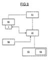
- the radiology apparatus comprises, in addition to the central unit 20 and collimation device 1, an X-ray tube 60 integral with the collimation device 1, a high-voltage generator 61 for powering the tube 60, a receiver 62, provided, for example, with a scintillator and a matrix camera, and a monitor 63 provided with a screen 64 for the display of X-ray images.
- the present invention makes it possible to design tools for automatic testing of an electromagnetic ray imaging and processing apparatus.
- the test tools can come in the form of a kit that is added to an existing collimator or can be integrated with a collimator. Remote image quality control can thus be carried out with diagnosis in real time and preventive maintenance.
- the test tool rests permanently on the imaging apparatus and possesses a deactivated position in which the beam of electromagnetic rays does not encounter any obstacle. The image taken in normal operation of the imaging apparatus does not therefore undergo any attenuation or diminution of quality.
- the radiology apparatus whose control unit is connected to the test tool is advantageously provided with a remote link, digital, for example, to a maintenance center, which makes it possible to perform a number of maintenance operations without the service call of a maintenance operator.
Landscapes
- Health & Medical Sciences (AREA)
- Life Sciences & Earth Sciences (AREA)
- Engineering & Computer Science (AREA)
- Physics & Mathematics (AREA)
- Medical Informatics (AREA)
- High Energy & Nuclear Physics (AREA)
- General Health & Medical Sciences (AREA)
- Heart & Thoracic Surgery (AREA)
- Biophysics (AREA)
- Pathology (AREA)
- Radiology & Medical Imaging (AREA)
- Biomedical Technology (AREA)
- Nuclear Medicine, Radiotherapy & Molecular Imaging (AREA)
- Molecular Biology (AREA)
- Surgery (AREA)
- Animal Behavior & Ethology (AREA)
- Optics & Photonics (AREA)
- Public Health (AREA)
- Veterinary Medicine (AREA)
- Spectroscopy & Molecular Physics (AREA)
- General Engineering & Computer Science (AREA)
- Toxicology (AREA)
- Apparatus For Radiation Diagnosis (AREA)
- Measurement Of Radiation (AREA)
Abstract
Description
- The present invention concerns the field of electromagnetic radiation beams used for different types of measurement and visualization. The invention is applicable notably to X-ray imaging or processing devices, for example, in the medical field.
- A radiology apparatus generally comprises means for an X-ray emission having equipped with an X-ray tube and a collimator, means for receiving the X-ray emissions separated from the means for emission by a distance sufficient to place there an object that it is desired to study. The collimator serves to determine the solid angle of aperture of the X-ray beam. The X-ray beam can thus be limited to the surface of the receiver. The collimator can also serve to further reduce the solid angle of the beam in order to limit it to a particular zone of interest of the object that is studied or processed, which makes it possible to prevent other parts of the object from being subjected to X-rays. The collimator can include a diaphragm made according to the principle of the diaphragm of a camera of articulated moving plane type. A diaphragm whose attenuating material consists of a deformable solid or of a fluid in a chamber is also disclosed in FR-A-2,601,544.
- In addition, a radiology apparatus further comprises an electronic control unit for the X-ray tube, collimator, receiver (provided, for example, with a scintillator), a high-voltage supply of the X-ray tube, etc.
- Such an apparatus must be calibrated in order to attain a sufficient qualitative and quantitative precision of the structures observed on an image. The calibration is generally done by means of a phantom that is placed at the object site on the path of the X-ray beam. A phantom is an object separate from the apparatus and comprising parts opaque to X-rays arranged according to a geometry defined and known. An image of the phantom is acquired under the geometric conditions of an angle of incidence that it is sought to be calibrated. The projections of the characteristic points are then recognized in the image. Each characteristic point of the object is associated with its trace in the acquired image. The system of equation describing the projection supplying the image is inverted in the mathematical sense and the set of parameters of the projection is finally obtained for the given vantage point. A phantom and method of calibration of an X-ray imaging system is disclosed in FR-A-2,700,909 and EP-A-0,874,536.
- An embodiment of the present invention is directed to increasing the automation of calibration of a system using electromagnetic radiation. An embodiment of the present invention proposes controlling the calibration. Tan embodiment of the present invention proposes a phantom whose risks of deterioration are reduced.
- A collimation device, according to one embodiment of the invention, is of the type intended to direct an energy beam in a given direction and at a given solid angle. The collimation device is capable of being installed on output of an energy beam generating means and of being connected to the control unit. The collimation device includes means for testing operation of the assembly formed by the energy beam generating means, the collimation device, the control device and a receiver. The means can be integrated with the device, for example, by being adjacent to the collimation elements. The means can be connected to the control unit directly or indirectly. The collimation device advantageously includes means for calibrating the operating parameters intended to be used by the control unit. In an embodiment of the invention, the collimation device includes means for testing the operation of an X-ray tube emitting the energy beam. The means are preferably capable of being commanded by a control unit. In an embodiment of the invention, the means are capable of being remote-controlled by a computer installed on another site.
- In an embodiment of the invention, the means include a plurality of test tools with a position sensor of each tool. The collimation device can include a motion sensor of each tool. The progress or temporal change of the calibration can then be monitored.
- A radiology apparatus, according to one aspect of the invention, means for emitting an energy beam means of reception for the energy beam, a control unit and a collimation device, such as described above.
- A test kit, according to one embodiment of the invention, includes means for fastening to a collimation device, of the type designed to direct an energy beam in a given direction and at a given solid angle and means for testing the operation of the collimation device means for emitting energy beam and a control unit. The test kit can advantageously be equipped with means for communicating with the control unit. The test kit is therefore capable of being fastened to collimation device, notably, below the latter in the direction of propagation of the energy beam. The test kit can be fastened on a collimation device with little or no structural modifications.
- The invention also proposes a method for testing a radiology apparatus, in which the operation of the apparatus is tested by means of tools forming part of a collimation device, the tools making it possible to functionally define the operation of the means for emitting an energy beam of the collimation device and of a receiver.
- The invention is also directed to a computer program including means for providing a program code for applying the steps of the above-mentioned method.
- The invention likewise is directed to a storage medium capable of being read by a device for reading the program code which are stored there in and which are capable of applying the steps of the abovementioned method.
- The invention also makes possible a remote control of the quality of operation of an apparatus, notably of a radiology apparatus, by making possible a calibration remote-controlled from a maintenance center, for example, with telecommunication through an Internet-type network, or an automatic calibration at given time intervals or operating times, while providing for the possibility that a negative result of automatic calibration might trip an alarm in a maintenance center which can also be remotely situated.
- For that purpose, the collimation device may comprise: one or more lead plates for calibration of the X-ray tube that is done by emitting X-rays; one or more copper plates for calibration of the gain response of the entire information processing system formed by the apparatus, which makes it possible to characterize, notably, the aging of the X-ray tube; one or more aluminum plates for spectral characterization of the X-ray beam and dose measurement. Several aluminum plates will preferably be provided to determine at what thickness of aluminum the dose is divided by a given factor; one or more wires of radiation-absorbent material; one or more grids of radiation-absorbent material; one or more plates of radiation-absorbent material of thickness calibrated in steps to make calibration of the image quality possible.
- The persistence or kinetic blur due, for example, to the scintillator, which continues to emit an output signal when the input signal (X-rays) has been interrupted can be calibrated. The progress of persistence is monitored by placing one or more test objects in the beam, automatically controlling the speed and position of the test objects.
- The invention will now be described in greater detail, by way of example, with reference to the drawings, in which:-
- Figure 1 is a schematic view of a collimator;
- Figures 2, 4, 6 and 7 are schematic views in perspective of test tools;
- Figure 3 is a schematic view of a test kit;
- Figure 5 is a schematic side view in elevation of the test tool of Figure 4;
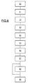
- Figure 8 is a diagram of steps of operation; and
- Figure 9 is a diagram of an architecture of a radiology apparatus.
-
- In Figure 1, a
collimation device 1 comprises acasing 2 provided with aninlet 3, anoutlet 4 and a plurality ofmoving plates 5 to 12 opaque to X-rays.Plates 5 to 12 provide a collimation according to a rectangular format of anX-ray beam 13 represented by a line of dots and dashes being propagated on an axis 14. The beam emanates from afocus 15 situated in an X-ray tube not represented. Collimation makes it possible to adapt the beam to the shapes of rectangular detectors of film, scintillator and CCD camera type, or solid state detectors, or organs crossed by the X-ray beam. - The
collimation device 1 also includes anadditional casing 16 placed in contact with thelower aperture 4 ofcasing 2 and also arranged to be transparent to X-rays. Insidecasing 16, there is adisk 17 rotary-mounted and driven by amotor 18, the rotation being detected by asensor 19, for example, of optical type reading an optical coder, not represented, which can comprise a sequence of alternate light and dark zones arranged on the upper surface of thedisk 17, close to its periphery, opposite thesensor 19. - An embodiment of the
disk 17 is illustrated in Figure 2. Thedisk 17 comprises a plurality, for example seven, of circular zones 22 to 28. The diameter and the positioning of the circular zones 22 to 28 on thedisk 17 are such that theX-ray beam 13 illustrated in Figure 1 presents a diameter slightly less than that of one of the circular zones 22 to 28, when it crosses one of the circular zones 22 to 28. Circular zone 22 is empty and is used in normal operation of a radiology apparatus, for example, on taking an X-ray image of a patient.Circular zone 23 is an aluminum plate of given thickness that allows testing of the variation of spectral quality due to aging of the X-ray tube, which makes it possible to determine when it is advisable to change the tube in order to avoid a shutdown of the radiology apparatus due to a malfunction. The information on change of spectral quality can also be used for calibration of the exposure parameters, such as high service voltage of the X-ray tube, service current, etc.Circular zone 24 comprises a two-dimensional phantom such as a metal grid of given material and thickness.Circular zone 25 also comprises a phantom, for example, in the form of a sheet with defined beveled edges. Those two phantoms make possible an evaluation of image quality.Circular zone 26 comprises a plate of heavy metal, for example, 2 mm thickness of lead, which makes it possible to totally block the X-ray beam.Circular zone 27 comprises a copper plate of given thickness, for example, 2 mm.Circular zone 28 also comprises a copper plate of different thickness fromcircular zone 27. Bothcircular zones - A
motor 18 for turning thedisk 17 on instruction of the radiologyapparatus control unit 20, allows the different steps of calibration to proceed automatically. The intervention of an operator can be reduced to the decision to initiate calibration. The operator can be located on site or at a remote maintenance center connected by digital link to the radiology apparatus. Calibration can also be carried out automatically, for example, outside of normal working hours of the radiology apparatus and the necessary adjustments of the parameters of the radiology apparatus can be made while being able to signal a fault requiring attention by means of a local alarm and/or to a remote maintenance center. Asensor 19, makes it possible to ascertain the position and possibly the speed of rotation of thedisk 17, is also connected to thecontrol unit 20 of the radiology apparatus. - As can be seen in Figure 1, the
control unit 20 is joined by awire connection 21 to the operation test means formed by thecasing 16 equipped with thedisk 17,motor 18 andsensor 19. However, a wireless link or even a connection throughcasing 2 could also be provided. Thecontrol unit 20 can be dedicated to the operation test means, or dedicated to thecollimation device 1, or can form a central control unit of the radiology apparatus to which thecollimation device 1 is a part. Thecontrol unit 20 includes at least one processor, at least one memory and at least one set of control instructions stored in memory and capable of being executed by the processor. -
Casing 16 andcasing 2 can be interlocked, for example, by means of screws, not represented.Casings casing 2, it can be arranged to add an operation test means to the collimation device in the existing radiology apparatus, as shown in Figure 3. In the latter case, the test means may be in the form of atest kit 29 having a general shape similar to the test means of the embodiment of Figure 1 and provided, in addition, with twolugs - In Figures 4 and 5, another test tool is illustrated, which can be placed inside a test means casing. The
tool 34 has acylindrical structure 35 around which is placed a plurality ofrectangular elements 36 comprising the same type of elements as the circular zones 22 to 28 illustrated in Figure 2. - In the embodiment illustrated in Figure 6, a
test tool 37 comprises a plurality ofsquare test elements 38 to 41, each hinged at an angle on anaxis 42 ready to be placed on the path of anX-ray beam 43 that is represented here as a beam of parallel lines. - Of course, in both of the foregoing embodiments, the rotation of the
tool 34 and ofelements 38 to 41 of thetool 37 is motor-driven and monitored by sensor(s) so that the control unit receives information on the position and possibly the movement of these different elements. - In the embodiment illustrated in Figure 7, the
test tool 44 comprises twoblocks blocks X-ray beam 43 crosses the twoblocks X-ray beam 43. The relative position of theblocks - Different steps used by a radiology apparatus control unit are illustrated by way of example in Figure 8 by means of a routine stored in an internal memory of the control unit or outside the control unit.
- At
step 50, a routine of the control unit, which is dedicated to calibration, verifies the time elapsed since the last calibration and compares it with a predetermined ceiling. If the time elapsed is greater than the ceiling, one then proceeds to step 51; otherwise the program is halted in order to be resumed later, for example, the next day at the same time or after a few minutes of non-use of the radiology apparatus. Atstep 51, the program controls the movement of a test tool and, by considering thedisk 17 of Figure 2, the positioning ofcircular zone 23 in place of circular zone 22, which is empty, on the path of thebeam 13. Then, a standard calibration is carried out with thecircular zone 23. Atsteps 52 to 56, the program controls the corresponding operations forcircular zones 24 to 28. - At
stage 57, the routine controls the movement of thedisk 17, so that circular zone 22, which is empty, is placed on the path of thebeam 13. If, in the course of one ofsteps 52 to 56, calibration reveals a fault which the control unit cannot remedy by itself, the program controls analarm stage 58 either on site, for example, on a screen of the radiology apparatus, or at a remote maintenance center, the alarm being advantageously accompanied by a message relating to the nature of the fault, its seriousness, a down time of the radiology apparatus, etc. Otherwise, calibration is terminated and the time elapsed since the last calibration is reset atstep 59. - In Figure 9, the radiology apparatus comprises, in addition to the
central unit 20 andcollimation device 1, anX-ray tube 60 integral with thecollimation device 1, a high-voltage generator 61 for powering thetube 60, areceiver 62, provided, for example, with a scintillator and a matrix camera, and amonitor 63 provided with ascreen 64 for the display of X-ray images. - The present invention makes it possible to design tools for automatic testing of an electromagnetic ray imaging and processing apparatus. The test tools can come in the form of a kit that is added to an existing collimator or can be integrated with a collimator. Remote image quality control can thus be carried out with diagnosis in real time and preventive maintenance. The test tool rests permanently on the imaging apparatus and possesses a deactivated position in which the beam of electromagnetic rays does not encounter any obstacle. The image taken in normal operation of the imaging apparatus does not therefore undergo any attenuation or diminution of quality.
- It is important to know precisely the movement of a tool across the beam in order to be able to deduce therefrom an estimate of the remanence and to monitor the progress of remanence in the course of time, that is, aging of the
receiver 62 and, notably, of the scintillator. For that purpose, a tool will be moved in a few milliseconds in the X-ray beam intermittently and at constant speed. - The radiology apparatus whose control unit is connected to the test tool is advantageously provided with a remote link, digital, for example, to a maintenance center, which makes it possible to perform a number of maintenance operations without the service call of a maintenance operator.
- Other maintenance operations can be carried out with the service call of a maintenance operator, who will have identified the component to be replaced before his trip, which will also make it possible to reduce the number of trips.
- The handling of a phantom separate from the apparatus becomes superfluous, which reduces the risks of loss or deterioration of the phantom likely to distort the calibration.
Claims (11)
- Collimation device (1) of the type intended to direct an energy beam (13) in a given direction and at a given solid angle, the collimation device being capable of being installed at an output of means for emission of an energy beam and of being connected to a control unit, comprising means for testing operation of the assembly formed by the means for emission of an energy beam, the collimation device, means for receiving the energy beam receiver and the control unit, the means for testing comprising means to include a plurality of test tools (22-28) with a sensor (19) of the position of each tool.
- Collimation device according to claim 1 comprising means for calibrating the operating parameters intended to be used by the control unit.
- Collimation device according to claim 1 or 2 comprising means for testing the operation of an energy beam emission tube.
- Collimation device according to any one of the foregoing claims wherein the means are capable of being commanded by the control unit.
- Collimation device according to any one of the foregoing claims, wherein the means are capable of being remote-controlled by a computer installed on another site.
- Collimation device according to claim 1 comprising a motion sensor for each tool.
- Radiology apparatus, including means for emission of an energy beam, means for reception for the energy beam, a control unit and a collimation device, according to any one of the foregoing claims.
- A test kit (29) comprising means for fastening to a collimation device, of the type designed to direct an energy beam in a given direction and at a given solid angle, and means for testing the operation of the collimation device, means for emission of the energy beam and a control unit, the means for testing comprising means include a plurality of test tools (22-28) with a sensor (19) of the position of each tool.
- A method of testing a radiology apparatus, in which the operation of the radiology apparatus is tested by means of tools forming part of a collimation device, the tools making it possible to functionally define the operation of the means for emission of an energy beam, the collimation device and means for receiving the energy beam, the means for testing comprising means to include a plurality of test tools (22-28) with a sensor (19) of the position of each tool..
- Computer program including program code means for applying the steps of the method according to claim 9.
- A storage medium capable of being read by means for reading program code which are stored therein and which are capable of applying the steps of the method according to claim 9.
Applications Claiming Priority (2)
| Application Number | Priority Date | Filing Date | Title |
|---|---|---|---|
| FR0007745A FR2810444B1 (en) | 2000-06-16 | 2000-06-16 | COLLIMATION DEVICE, RADIOLOGY APPARATUS, TEST KIT, AND TESTING METHOD OF RADIOLOGY APPARATUS |
| FR0007745 | 2000-06-16 |
Publications (2)
| Publication Number | Publication Date |
|---|---|
| EP1164598A1 true EP1164598A1 (en) | 2001-12-19 |
| EP1164598B1 EP1164598B1 (en) | 2005-06-01 |
Family
ID=8851369
Family Applications (1)
| Application Number | Title | Priority Date | Filing Date |
|---|---|---|---|
| EP01305148A Expired - Lifetime EP1164598B1 (en) | 2000-06-16 | 2001-06-13 | Collimation device, radiology apparatus, test kit, method of testing a radiology apparatus, computer program including a program code for applying said method and storage medium capable of being read by means for reading said program code |
Country Status (5)
| Country | Link |
|---|---|
| US (2) | US6850596B2 (en) |
| EP (1) | EP1164598B1 (en) |
| JP (1) | JP5377809B2 (en) |
| DE (1) | DE60111124T2 (en) |
| FR (1) | FR2810444B1 (en) |
Cited By (2)
| Publication number | Priority date | Publication date | Assignee | Title |
|---|---|---|---|---|
| WO2003067937A3 (en) * | 2002-02-05 | 2003-11-13 | Philips Intellectual Property | Method and device for automatic testing of an x-ray system |
| EP2114251A4 (en) * | 2007-02-19 | 2014-11-26 | Univ Western Ontario | APPARATUS FOR ASSISTING DETERMINATION OF QUANTA DETECTION EFFICIENCY |
Families Citing this family (17)
| Publication number | Priority date | Publication date | Assignee | Title |
|---|---|---|---|---|
| EP0964362A1 (en) * | 1998-04-07 | 1999-12-15 | Canon Kabushiki Kaisha | Image processing method, apparatus, and storage medium for recognition of irradiation area |
| ATE321818T1 (en) * | 2001-10-18 | 2006-04-15 | Kraton Polymers Res Bv | SOLID CURABLE POLYMER COMPOSITION |
| US6895076B2 (en) * | 2003-06-03 | 2005-05-17 | Ge Medical Systems Global Technology Company, Llc | Methods and apparatus for multiple image acquisition on a digital detector |
| AU2003281908A1 (en) * | 2003-11-20 | 2005-06-08 | Ge Medical Systems Global Technology Company, Llc. | Collimator, x-ray irradiator, and x-ray apparatus |
| DE102004012050B4 (en) * | 2004-03-11 | 2008-01-10 | Siemens Ag | Aperture unit and associated X-ray source or method for their adjustment for fading in an examination area or X-ray device |
| DE102005028208A1 (en) * | 2005-06-17 | 2006-12-28 | Siemens Ag | Radiation diaphragm for an X-ray device |
| CN100454039C (en) * | 2005-09-22 | 2009-01-21 | 同方威视技术股份有限公司 | An integrated structure of a ray generator, a beam guide box, and front and rear collimators |
| US7298820B2 (en) * | 2006-03-31 | 2007-11-20 | Wisconsin Alumni Research Foundation | Portal imaging using modulated treatment beam |
| DE102006042726A1 (en) * | 2006-09-12 | 2008-03-27 | Siemens Ag | multileaf collimator |
| US7714293B2 (en) * | 2007-01-06 | 2010-05-11 | General Electric Company | Methods and apparatus for keystone effect |
| US7397901B1 (en) * | 2007-02-28 | 2008-07-08 | Varian Medical Systems Technologies, Inc. | Multi-leaf collimator with leaves formed of different materials |
| CN101859608B (en) * | 2009-04-09 | 2014-07-09 | Ge医疗系统环球技术有限公司 | Blade device and X-ray imager |
| JP5859232B2 (en) * | 2011-07-08 | 2016-02-10 | 国立大学法人東北大学 | Evaluation aids and evaluation devices |
| KR101429173B1 (en) * | 2013-08-05 | 2014-08-12 | 연세대학교 산학협력단 | Collimator and inspecting system using the same |
| CN108293289B (en) * | 2015-12-01 | 2022-09-13 | 皇家飞利浦有限公司 | Determining a condition of an X-ray tube of an X-ray system |
| JP6014744B2 (en) * | 2015-12-16 | 2016-10-25 | 国立大学法人東北大学 | Evaluation aids and evaluation devices |
| IT201800000868A1 (en) * | 2018-01-15 | 2019-07-15 | Ims Giotto S P A | METHOD OF CALIBRATION OF A COLLIMATOR AND EQUIPMENT FOR ANALYSIS TO X-RAYS CONFIGURED TO PERFORM THIS METHOD. |
Citations (3)
| Publication number | Priority date | Publication date | Assignee | Title |
|---|---|---|---|---|
| US5056130A (en) * | 1989-10-06 | 1991-10-08 | The United States Of America As Represented By The Administrator, National Aeronautics And Space Administration | Computerized tomography calibrator |
| DE19707728A1 (en) * | 1997-02-26 | 1998-08-27 | Siemens Ag | X-ray diagnostics arrangement |
| EP0874536A1 (en) * | 1997-03-31 | 1998-10-28 | General Electric Company | Apparatus and method for automatic monitoring and assessment of image quality in X-ray systems |
Family Cites Families (12)
| Publication number | Priority date | Publication date | Assignee | Title |
|---|---|---|---|---|
| DE2347178B2 (en) * | 1973-09-19 | 1975-09-18 | Siemens Ag, 1000 Berlin Und 8000 Muenchen | X-ray diagnostic apparatus |
| US4023036A (en) * | 1975-06-16 | 1977-05-10 | University Patents, Inc. | Apparatus and method for transverse tomography |
| JPS5643784Y2 (en) * | 1978-07-24 | 1981-10-14 | ||
| US4246488A (en) * | 1979-03-09 | 1981-01-20 | Picker Corporation | Radiation collimator |
| JPS59177405U (en) * | 1983-05-13 | 1984-11-27 | 株式会社 日立メデイコ | Inspection equipment for digital radiography equipment |
| FR2601544A1 (en) | 1986-07-08 | 1988-01-15 | Thomson Csf | DIAPHRAGM FOR BEAM OF ELECTROMAGNETIC RADIATION AND ITS USE IN A DEVICE FOR COLLIMATING THIS BEAM |
| NL8801094A (en) * | 1988-04-27 | 1989-11-16 | Philips Nv | METHOD AND APPARATUS FOR MEASURING INERTIA IN ROENT GENERATION SYSTEMS |
| US6229145B1 (en) * | 1992-01-22 | 2001-05-08 | Pem Technologies, Inc. | Dedicated apparatus and method emission mammography |
| FR2700909B1 (en) | 1993-01-27 | 1995-03-17 | Gen Electric Cgr | Device and automatic method for geometric calibration of an X-ray imaging system. |
| US5394455A (en) * | 1993-04-30 | 1995-02-28 | The Regents Of The University Of California | Digitally aided microfluoroscopy and fluorospot system and method of using the same |
| JP3168824B2 (en) * | 1994-04-30 | 2001-05-21 | 株式会社島津製作所 | X-ray CT system |
| US6285902B1 (en) * | 1999-02-10 | 2001-09-04 | Surgical Insights, Inc. | Computer assisted targeting device for use in orthopaedic surgery |
-
2000
- 2000-06-16 FR FR0007745A patent/FR2810444B1/en not_active Expired - Fee Related
-
2001
- 2001-06-12 US US09/879,488 patent/US6850596B2/en not_active Expired - Lifetime
- 2001-06-13 EP EP01305148A patent/EP1164598B1/en not_active Expired - Lifetime
- 2001-06-13 DE DE60111124T patent/DE60111124T2/en not_active Expired - Lifetime
- 2001-06-15 JP JP2001180943A patent/JP5377809B2/en not_active Expired - Fee Related
-
2004
- 2004-06-14 US US10/867,536 patent/US7021118B2/en not_active Expired - Fee Related
Patent Citations (3)
| Publication number | Priority date | Publication date | Assignee | Title |
|---|---|---|---|---|
| US5056130A (en) * | 1989-10-06 | 1991-10-08 | The United States Of America As Represented By The Administrator, National Aeronautics And Space Administration | Computerized tomography calibrator |
| DE19707728A1 (en) * | 1997-02-26 | 1998-08-27 | Siemens Ag | X-ray diagnostics arrangement |
| EP0874536A1 (en) * | 1997-03-31 | 1998-10-28 | General Electric Company | Apparatus and method for automatic monitoring and assessment of image quality in X-ray systems |
Cited By (4)
| Publication number | Priority date | Publication date | Assignee | Title |
|---|---|---|---|---|
| WO2003067937A3 (en) * | 2002-02-05 | 2003-11-13 | Philips Intellectual Property | Method and device for automatic testing of an x-ray system |
| JP2005516706A (en) * | 2002-02-05 | 2005-06-09 | コーニンクレッカ フィリップス エレクトロニクス エヌ ヴィ | Method and apparatus for automatically testing an X-ray system |
| US7125166B2 (en) | 2002-02-05 | 2006-10-24 | Koninklijke Philips Electronics, N.V. | Method and device for automatic testing of an X-ray system |
| EP2114251A4 (en) * | 2007-02-19 | 2014-11-26 | Univ Western Ontario | APPARATUS FOR ASSISTING DETERMINATION OF QUANTA DETECTION EFFICIENCY |
Also Published As
| Publication number | Publication date |
|---|---|
| FR2810444B1 (en) | 2006-11-24 |
| EP1164598B1 (en) | 2005-06-01 |
| US7021118B2 (en) | 2006-04-04 |
| US20040223591A1 (en) | 2004-11-11 |
| US6850596B2 (en) | 2005-02-01 |
| FR2810444A1 (en) | 2001-12-21 |
| JP5377809B2 (en) | 2013-12-25 |
| US20010053199A1 (en) | 2001-12-20 |
| JP2002095659A (en) | 2002-04-02 |
| DE60111124T2 (en) | 2006-05-04 |
| DE60111124D1 (en) | 2005-07-07 |
Similar Documents
| Publication | Publication Date | Title |
|---|---|---|
| EP1164598B1 (en) | Collimation device, radiology apparatus, test kit, method of testing a radiology apparatus, computer program including a program code for applying said method and storage medium capable of being read by means for reading said program code | |
| US6151383A (en) | Radiographic testing system with learning-based performance prediction | |
| EP2247240B1 (en) | Optical alignment system and alignment method for radiographic x-ray imaging | |
| EP2210560B1 (en) | A system and method to manage maintenance of a radiological imaging system | |
| US4763343A (en) | Method and structure for optimizing radiographic quality by controlling X-ray tube voltage, current, focal spot size and exposure time | |
| JP3197559B2 (en) | Computer X-ray tomography apparatus using image enhanced detector | |
| US6333962B1 (en) | Non-destructive inspection apparatus and inspection system using it | |
| EP1549115B1 (en) | Exposure calculation method and radiography system | |
| EP2290659A1 (en) | Portable X-ray detector with grid sensing unit and X-ray imaging system for automatic exposure setting for the portable X-ray detector | |
| US7522709B2 (en) | X-ray examination apparatus and x-ray examination method using the same | |
| US8050383B2 (en) | Radiographic apparatus and radiographic method | |
| JP2003210444A (en) | Radiation imaging equipment | |
| CA3013358A1 (en) | System and method for adjusting dental x-ray exposure | |
| US6521886B2 (en) | Method of monitoring changes in the detective quantum efficiency of an x-ray detector | |
| KR102324365B1 (en) | real-time monitoring system and method for therapeutic radiation based on plastic scintillating plate | |
| JP6905314B2 (en) | Radiation imaging equipment, radiography systems, radiography methods, and programs | |
| Hendee et al. | Performance specifications for diagnostic x-ray equipment | |
| SU919662A1 (en) | Apparatus for determining radiation field limits in x-ray apparatus | |
| JP2006255216A (en) | X-ray diagnostic imaging apparatus | |
| Hendee et al. | Performance specifications for diagnostic radiologic equipment: a delicate interface between purchaser and supplier | |
| US7046763B2 (en) | Field and factory testable imaging detector | |
| Hashemi | Measurement of focal spots of X-ray tubes using a CT reconstruction approach on edge images of holes with a diameter larger than the focal spot and comparison to classical pinhole imaging | |
| Siedband | Quality assurance measurements in diagnostic radiology | |
| US7891873B2 (en) | System for automatic testing of a digital X-ray detector | |
| Tiefenbach et al. | Saskatchewan postal TLD quality assurance programme for diagnostic X ray equipment |
Legal Events
| Date | Code | Title | Description |
|---|---|---|---|
| PUAI | Public reference made under article 153(3) epc to a published international application that has entered the european phase |
Free format text: ORIGINAL CODE: 0009012 |
|
| AK | Designated contracting states |
Kind code of ref document: A1 Designated state(s): DE NL Kind code of ref document: A1 Designated state(s): AT BE CH CY DE DK ES FI FR GB GR IE IT LI LU MC NL PT SE TR |
|
| AX | Request for extension of the european patent |
Free format text: AL;LT;LV;MK;RO;SI |
|
| RIN1 | Information on inventor provided before grant (corrected) |
Inventor name: DESPONDS, LIONEL Inventor name: SUNDERMANN, DIETMAR Inventor name: DUFLOT, JEAN-LUC |
|
| 17P | Request for examination filed |
Effective date: 20020619 |
|
| AKX | Designation fees paid |
Free format text: DE NL |
|
| 17Q | First examination report despatched |
Effective date: 20030211 |
|
| GRAP | Despatch of communication of intention to grant a patent |
Free format text: ORIGINAL CODE: EPIDOSNIGR1 |
|
| RTI1 | Title (correction) |
Free format text: COLLIMATION DEVICE, RADIOLOGY APPARATUS, TEST KIT, METHOD OF TESTING A RADIOLOGY APPARATUS, COMPUTER PROGRAM INCLUDING A |
|
| RAP1 | Party data changed (applicant data changed or rights of an application transferred) |
Owner name: GE MEDICAL SYSTEMS GLOBAL TECHNOLOGY COMPANY, LLC |
|
| GRAS | Grant fee paid |
Free format text: ORIGINAL CODE: EPIDOSNIGR3 |
|
| GRAA | (expected) grant |
Free format text: ORIGINAL CODE: 0009210 |
|
| AK | Designated contracting states |
Kind code of ref document: B1 Designated state(s): DE NL |
|
| REF | Corresponds to: |
Ref document number: 60111124 Country of ref document: DE Date of ref document: 20050707 Kind code of ref document: P |
|
| PLBE | No opposition filed within time limit |
Free format text: ORIGINAL CODE: 0009261 |
|
| STAA | Information on the status of an ep patent application or granted ep patent |
Free format text: STATUS: NO OPPOSITION FILED WITHIN TIME LIMIT |
|
| 26N | No opposition filed |
Effective date: 20060302 |
|
| REG | Reference to a national code |
Ref country code: DE Ref legal event code: R082 Ref document number: 60111124 Country of ref document: DE Representative=s name: MAI DOERR BESIER EUROPEAN PATENT ATTORNEYS - E, DE Ref country code: DE Ref legal event code: R082 Ref document number: 60111124 Country of ref document: DE Representative=s name: MAI DOERR BESIER PATENTANWAELTE, DE |
|
| PGFP | Annual fee paid to national office [announced via postgrant information from national office to epo] |
Ref country code: NL Payment date: 20130626 Year of fee payment: 13 |
|
| REG | Reference to a national code |
Ref country code: NL Ref legal event code: V1 Effective date: 20150101 |
|
| PG25 | Lapsed in a contracting state [announced via postgrant information from national office to epo] |
Ref country code: NL Free format text: LAPSE BECAUSE OF NON-PAYMENT OF DUE FEES Effective date: 20150101 |
|
| PGFP | Annual fee paid to national office [announced via postgrant information from national office to epo] |
Ref country code: DE Payment date: 20170628 Year of fee payment: 17 |
|
| REG | Reference to a national code |
Ref country code: DE Ref legal event code: R119 Ref document number: 60111124 Country of ref document: DE |
|
| PG25 | Lapsed in a contracting state [announced via postgrant information from national office to epo] |
Ref country code: DE Free format text: LAPSE BECAUSE OF NON-PAYMENT OF DUE FEES Effective date: 20190101 |