EP1164577A2 - Method and apparatus for reproducing speech signals - Google Patents
Method and apparatus for reproducing speech signals Download PDFInfo
- Publication number
- EP1164577A2 EP1164577A2 EP01121724A EP01121724A EP1164577A2 EP 1164577 A2 EP1164577 A2 EP 1164577A2 EP 01121724 A EP01121724 A EP 01121724A EP 01121724 A EP01121724 A EP 01121724A EP 1164577 A2 EP1164577 A2 EP 1164577A2
- Authority
- EP
- European Patent Office
- Prior art keywords
- speech
- encoding
- unit
- unvoiced
- voiced
- Prior art date
- Legal status (The legal status is an assumption and is not a legal conclusion. Google has not performed a legal analysis and makes no representation as to the accuracy of the status listed.)
- Withdrawn
Links
Images


Classifications
-
- G—PHYSICS
- G10—MUSICAL INSTRUMENTS; ACOUSTICS
- G10L—SPEECH ANALYSIS OR SYNTHESIS; SPEECH RECOGNITION; SPEECH OR VOICE PROCESSING; SPEECH OR AUDIO CODING OR DECODING
- G10L19/00—Speech or audio signals analysis-synthesis techniques for redundancy reduction, e.g. in vocoders; Coding or decoding of speech or audio signals, using source filter models or psychoacoustic analysis
- G10L19/02—Speech or audio signals analysis-synthesis techniques for redundancy reduction, e.g. in vocoders; Coding or decoding of speech or audio signals, using source filter models or psychoacoustic analysis using spectral analysis, e.g. transform vocoders or subband vocoders
-
- G—PHYSICS
- G10—MUSICAL INSTRUMENTS; ACOUSTICS
- G10L—SPEECH ANALYSIS OR SYNTHESIS; SPEECH RECOGNITION; SPEECH OR VOICE PROCESSING; SPEECH OR AUDIO CODING OR DECODING
- G10L21/00—Processing of the speech or voice signal to produce another audible or non-audible signal, e.g. visual or tactile, in order to modify its quality or its intelligibility
- G10L21/04—Time compression or expansion
Definitions
- This invention relates to a method and apparatus for reproducing speech signals at a controlled speed.
- the encoding method may roughly be classified into time-domain encoding, frequency domain encoding and analysis/synthesis encoding.
- Examples of the high-efficiency encoding of speech signals include sinusoidal analysis encoding, such as harmonic encoding, multi-band excitation (MBE) encoding, sub-band coding (SBC), linear predictive coding (LPC), discrete cosine transform (DCT), modified DCT (MDCT) and fast Fourier transform (FFT).
- sinusoidal analysis encoding such as harmonic encoding, multi-band excitation (MBE) encoding, sub-band coding (SBC), linear predictive coding (LPC), discrete cosine transform (DCT), modified DCT (MDCT) and fast Fourier transform (FFT).
- the high-efficiency speech encoding method by the time-axis processing involves difficulties in expeditious time-axis conversion (modification) because of the necessity of performing voluminous processing operations subsequent to decoder outputting.
- speed control is performed in the time domain subsequent to decoding, the method cannot be used for bit rate conversion.
- the input speech signal is divided on the time axis in terms of pre-set encoding units to produce encoded parameters which are interpolated to produce modified encoded parameters for desired time points, and the speech signal is reproduced based on these modified encoded parameters.
- the input speech signal is divided on the time axis in terms of pre-set encoding units to produce encoded parameters which are interpolated to modified encoded parameters for desired time points, and the speech signal is then reproduced based on these modified encoded parameters.
- the speech is reproduced with a block length differing from that used for encoding, using encoded parameters obtained on dividing the input speech signal on the time axis in terms of pre-set block as units and encoding the divided speech signal in terms of the encoding blocks.
- the fundamental frequency and the number in a pre-set band of harmonics of the input encoded speech data are converted and the, number of data specifying the amplitude of a spectral component in each input harmonics is interpolated for modifying the pitch.
- the pitch frequency is modified at the time of encoding by dimensional conversion in which the number of harmonics is set at a pre-set value.
- the decoder for speech compression may be used simultaneously as a speech synthesizer for text speech synthesis.
- a speech synthesizer for text speech synthesis For routine speech pronunciation, clear playback speech is obtained by compression and expansion, whereas, for special speech synthesis, text synthesis or synthesis under the pre-determined rule is used for constituting an efficient speech output system.
- an input speech signal is divided in terms of pre-set encoding units on the time axis and encoded in terms of the encoding unit in order to find encoded parameters which are then interpolated to find modified encoded parameters for desired time points.
- the speech signal is then reproduced based on the modified encoded parameters, so that speed control over a wide range may be realized easily with high quality without changing the phoneme or pitch.
- the speech is reproduced with a block length differing from that used for encoding, using encoded parameters obtained on dividing the input speech signal on the time axis in terms of pre-set block as units and on encoding the divided speech signal in terms of the encoding blocks.
- the fundamental frequency and the number in a pre-set band of harmonics of the input encoded speech data are converted and the number of data specifying the amplitude of a spectral component in each input harmonics is interpolated for modifying the pitch.
- the result is that the pitch may be changed to a desired value by a simplified structure.
- the decoder for speech compression may be used simultaneously as the speech synthesizer for text speech synthesis.
- the speech synthesizer for text speech synthesis For routine speech pronunciation, clear playback speech is obtained by compression and expansion, whereas, for special speech synthesis, text synthesis or synthesis under rule is used for constituting an efficient speech output system.
- the pitch-converted to pitch-controlled speech signals can be transmitted or received by a simplified structure.
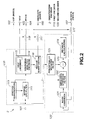
- the present embodiment is directed to a speech signal reproducing apparatus 1 for reproducing speech signals based on encoding parameters as found by dividing the input speech signals on the time axis in terms of a pre-set number of frames as encoding units and encoding the divided input speech signals, as shown in Fig. 1.
- the speech signal reproducing apparatus 1 includes an encoding unit 2 for encoding the speech signals entering an input terminal 101 in terms of frames as units for outputting encoded parameters such as linear prediction encoding (LPC) parameters, line spectrum pair (LSP) parameters, pitch, voiced (V)/unvoiced (UV) or spectral amplitudes Am, and a period modification unit 3 for modifying an output period of the encoding parameters by time axis compansion.
- the speech signal reproducing apparatus also includes a decoding unit 4 for interpolating the encoded parameters outputted at the period modified by the period modification unit 3 for finding the modified encoded parameters for desired time points and for synthesizing the speech signals based on the modified encoded parameters for outputting the synthesized speech signals at an output terminal 201.
- the encoding unit 2 is explained by referring to Figs.2 and 3.
- the encoding unit 2 decides, based on the results of discrimination, whether the input speech signal is voiced or unvoiced, and performs sinusoidal synthetic encoding for a signal portion found to be voiced, while performing vector quantization by a closed-loop search of the optimum vector using an analysis-by-synthesis method for a signal portion found to be unvoiced, for finding the encoded parameters.
- the encoding unit 2 includes a first encoding unit 110 for finding short-term prediction residuals of the input speech signal, such as linear prediction coding (LPC) residuals, to perform sinusoidal analysis encoding, such as harmonic encoding, and a second encoding unit 120 for performing waveform coding by transmitting phase components of the input speech signal.
- the first encoding unit 110 and the second encoding unit 120 are used for encoding the voiced (V) portion and the unvoiced (UV) portion, respectively.
- the speech signal supplied to the input terminal 101 is sent to an inverted LPC filter 111 and an LPC analysis quantization unit 113 of the first encoding unit 110.
- the LPC coefficient obtained from the LPC analysis/quantization unit 113 or the so-called ⁇ -parameter is sent to the inverted LPC filter 111 for taking out the linear prediction residuals (LPC residuals) of the input speech signal by the inverse LPC filter 111.
- LPC residuals linear prediction residuals
- LSP linear spectral pairs
- the LPC residuals from the inverted LPC filter 111 are sent to a sinusoidal analysis encoding unit 114.
- the sinusoidal analysis encoding unit 114 performs pitch detection, spectral envelope amplitude calculations and V/UV discrimination by a voiced (V)/ unvoiced (UV) discrimination unit 115.
- the spectral envelope amplitude data from the sinusoidal analysis encoding unit 114 are sent to the vector quantization unit 116.
- the codebook index from the vector quantization unit 116, as a vector-quantized output of the spectral envelope, is sent via a switch 117 to an output terminal 103, while an output of the sinusoidal analysis encoding unit 114 is sent via a switch 118 to an output terminal 104.
- the V/UV discrimination output from the V/UV discrimination unit 115 is sent to an output terminal 105 and to the switches 117, 118 as switching control signals.
- the index and the pitch are selected so as to be taken out at the output terminals 103, 104.
- a suitable number of dummy data for interpolating amplitude data of an effective band block on the frequency axis from the last amplitude data in the block as far as the first amplitude data in the block, or dummy data extending the last data and the first data in the block are appended to the trailing end and to the leading end of the block, for enhancing the number of data to N F .
- an Os-tuple number of amplitude data are found by band-limiting type Os-tuple oversampling, such as octatuple oversampling.
- the Os-tuple number of the amplitude data ((mMx + 1) ⁇ Os number of data) is further expanded to a larger number of N M , such as 21048, by linear interpolation.
- This N M number data is converted into the pre-set number M (such as 44) by decimation and vector quantization is then performed on the pre-set number of data.
- the second encoding unit 120 has a code excited linear predictive (CELP) coding configuration and performs vector quantization on the time-domain waveform by a closed-loop search employing an analysis-by-synthesis method.
- CELP code excited linear predictive
- an output of a noise codebook 121 is synthesized by a weighted synthesis filter 122 to produce a weighted synthesized speech which is sent to a subtractor 123 where an error between the weighted synthesized speech and the speech supplied to the input terminal 101 and subsequently processed by a perceptually weighting filter 125 is found.
- a distance calculation circuit 124 calculates the distance and a vector which minimizes the error is searched in the noise codebook 121.
- This CELP encoding is used for encoding the unvoiced portion as described above.
- the codebook index as the UV data from the noise codebook 121 is taken out at an output terminal 107 via a switch 127 which is turned on when the results of V/UV discrimination from the V/UV discrimination unit 115 indicates an unvoiced (UV) sound.
- FIG. 3 a more detailed structure of a speech signal encoder shown in Fig. 1 is now explained.
- Fig.3 the parts or components similar to those shown in Fig. 1 are denoted by the same reference numerals.
- the speech signals supplied to the input terminal 101 are filtered by a high-pass filter 109 for removing signals of an unneeded range and thence supplied to an LPC analysis circuit 132 of the LPC analysis/quantization unit 113 and to the inverse LPC filter 111.
- the LPC analysis circuit 132 of the LPC analysis/ quantization unit 113 applies a Hamming window, with a length of the input signal waveform on the order of 256 samples as a block, and finds linear prediction coefficients, that is so-called ⁇ -parameters, by the self-correlation method.
- the framing interval as a data outputting unit is set to approximately 160 samples. If the sampling frequency fs is 8 kHz, for example, a one-frame interval is 20 msec or 160 samples.
- the ⁇ -parameters from the LPC analysis circuit 132 are sent to an ⁇ -LSP conversion circuit 133 for conversion into line spectra pair (LSP) parameters.
- LSP line spectra pair
- the reason the ⁇ -parameters are converted into the LSP parameters is that the LSP parameters are superior in interpolation characteristics to the ⁇ -parameters.
- the LSP parameters from the ⁇ -LSP conversion circuit 133 are matrix- or vector-quantized by the LSP quantizer 134. It is possible to take a frame-to-frame difference prior to vector quantization, or to collect plural frames together in order to perform matrix quantization. In the present case, the LSP parameters, calculated every 20 msec, are vector-quantized, with 20 msec as a frame.
- the quantized output of the quantizer 134 that is the index data of the LSP quantization, are taken out to the decoding unit 103 at a terminal 102, while the quantized LSP vector is sent to an LSP interpolation circuit 136.
- the LSP interpolation circuit 136 interpolates the LSP vectors, quantized every 20 msec or 40 msec, in order to provide an octatuple rate. That is, the LSP vector is updated every 2.5 msec.
- the reason is that, if the residual waveform is processed with the analysis/synthesis by the harmonic encoding/decoding method, the envelope of the synthetic waveform presents an extremely sooth waveform, so that, if the LPC coefficients are changed abruptly every 20 msec, a foreign noise is likely to be produced. That is, if the LPC coefficient is changed gradually every 2.5 msec, such foreign noise may be prevented from being produced.
- the LSP parameters are converted by an LSP to ⁇ conversion circuit 137 into ⁇ -parameters as coefficients of, for example, ten-order direct type filter.
- An output of the LSP to ⁇ conversion circuit 137 is sent to the LPC inverted filter circuit 111 which then performs inverted filtering for producing a smooth output using ⁇ -parameters updated every 2.5 msec.
- An output of the inverted LPC filter 111 is sent to an orthogonal transform circuit 145, such as a DCT circuit, of the sinusoidal analysis encoding unit 114, such as a harmonic encoding circuit.
- the ⁇ -parameters from the LPC analysis circuit 132 of the LPC analysis/quantization unit 113 are sent to a perceptual weighting filter calculating circuit 139 where data for perceptual weighting is found. These weighting data are sent to the perceptual weighting vector quantizer 116, perceptual weighting filter 125 of the second encoding unit 120 and to the perceptual weighted synthesis filter 122.
- the sinusoidal analysis encoding unit 114 of the harmonic encoding circuit analyzes the output of the inverted LPC filter 111 by a method of harmonic encoding. That is, pitch detection, calculations of the amplitudes Am of the respective harmonics and voiced (V)/ unvoiced (UV) discrimination, are carried out, and the numbers of the amplitudes Am or the envelopes of the respective harmonics, varied with the pitch, are made constant by dimensional conversion.
- commonplace harmonic encoding is used.
- MBE multi-band excitation
- voiced portions and unvoiced portions are present in the frequency area or band at the same time point (in the same block or frame).
- harmonic encoding techniques it is uniquely judged whether the speech in one block or in one frame is voiced or unvoiced.
- a given frame is judged to be UV if the totality of the band is UV, insofar as the MBE encoding is concerned.
- the open-loop pitch search unit 141 and the zero-crossing counter 142 of the sinusoidal analysis encoding unit 114 of Fig.3 is fed with the input speech signal from the input terminal 101 and with the signal from the high-pass filter (HPF) 109, respectively.
- the orthogonal transform circuit 145 of the sinusoidal analysis encoding unit 114 is supplied with LPC residuals or linear prediction residuals from the inverted LPC filter 111.
- the open loop pitch search unit 141 takes the LPC residuals of the input signals to perform relatively rough pitch search by open loop.
- the extracted rough pitch data is sent to a fine pitch search unit 146 by closed loop search as later explained.
- the maximum value of the normalized autocorrelation r(p), obtained by normalizing the maximum value of the self-correlation, of the LPC residuals along with the rough pitch data, are taken out along with the rough pitch data so as to be sent to the V/UV discrimination unit 115.
- the orthogonal transform circuit 145 performs orthogonal transform, such as discrete Fourier transform (DFT), for converting the LPC residuals on the time axis into spectral amplitude data on the frequency axis.
- An output of the orthogonal transform circuit 145 is sent to the fine pitch search unit 146 and a spectral evaluation unit 148 for evaluating the spectral amplitude or envelope.
- DFT discrete Fourier transform
- the fine pitch search unit 146 is fed with relatively rough pitch data extracted by the open loop pitch search unit 141 and with frequency-domain data obtained by DFT by the orthogonal transform unit 145.
- the fine pitch search unit 146 swings the pitch data by ⁇ several samples, at a rate of 0.2 to 0.5, centered about the rough pitch value data, in order to arrive ultimately at the value of the fine pitch data having an optimum decimal point (floating point).
- the analysis by synthesis method is used as the fine search technique for selecting a pitch so that the power spectrum will be closest to the power spectrum of the original sound.
- Pitch data from the closed-loop fine pitch search unit 146 is sent to an output terminal 104 via a switch 118.
- the amplitude of each harmonics and the spectral envelope as the sum of the harmonics are evaluated based on the spectral amplitude and the pitch as the orthogonal transform output of the LPC residuals and sent to the fine pitch search unit 146, V/UV discrimination unit 115 and to the perceptually weighted vector quantization unit 116.
- the V/UV discrimination unit 115 discriminates V/UV of a frame based on an output of the orthogonal transform circuit 145, an optimum pitch from the fine pitch search unit 146, spectral amplitude data from the spectral evaluation unit 148, maximum value of the normalized self-correlation r(p) from the open loop pitch search unit 141 and the zero-crossing count value from the zero-crossing counter 142.
- the boundary position of the band-based V/UV discrimination for MBE may also be used as a condition for V/UV discrimination.
- a discrimination output of the V/UV discrimination unit 115 is taken out at the output terminal 105.
- An output unit of the spectrum evaluation unit 148 or an input unit of the vector quantization unit 116 is provided with a number of data conversion unit (a unit performing a sort of sampling rate conversion).
- the data number conversion unit is used for setting the amplitude data
- obtained from band to band, is changed in a range from 8 to 63.
- the data number conversion unit 119 converts the amplitude data of the variable number mMx + 1 to a pre-set number M of data, such as 44 data.
- This weight is supplied by an output of the perceptual weighting filter calculation circuit 139.
- the index of the envelope from the vector quantizer 116 is taken out by a switch 117 at an output terminal 103. Prior to weighted vector quantization, it is advisable to take inter-frame difference using a suitable leakage coefficient for a vector made up of a pre-set number of data.
- the second encoding unit 120 is explained.
- the second encoding unit 120 is of the code excited linear prediction (CELP) coding structure and is used in particular for encoding the unvoiced portion of the input speech signal.
- CELP code excited linear prediction
- a noise output corresponding to LPC residuals of an unvoiced speech portion as a representative output of the noise codebook, that is the so-called stochastic codebook 121 is sent via gain circuit 126 to the perceptually weighted synthesis filter 122.
- the speech signal supplied from the input terminal 101 via high-pass filter (HPF) 109 and perceptually weighted by the perceptually weighting filter 125 is fed to the subtractor 123 where a difference or error of the perceptually weighted speech signal from the signal from the synthesis filter 122 is found.
- This error is fed to a distance calculation circuit 124 for finding the distance and a representative value vector which will minimize the error is searched by the noise codebook 121.
- the shape index of the codebook from the noise codebook 121 and the gain index of the codebook from the gain circuit 126 are taken out.
- the shape index, which is the UV data from the noise codebook 121 is sent via a switch 127s to an output terminal 107s, while the gain index, which is the UV data of the gain circuit 126, is sent via a switch 127g to an output terminal 107g.
- switches 127s, 127g and the switches 117, 118 are turned on and off depending on the results of V/UV decision from the V/UV discrimination unit 115. Specifically, the switches 117, 118 are turned on, if the results of V/UV discrimination of the speech signal of the frame about to be transmitted indicates voiced (V), while the switches 127s, 127g are turned on if the speech signal of the frame about to be transmitted is unvoiced (UV).
- the encoded parameters, outputted by the encoding unit 2, are supplied to the period modification unit 3.
- the period modification unit 3 modifies an output period of the encoded parameters by time axis compression/expansion.
- the encoded parameters, outputted at a period modified by the period modification unit 3, are sent to the decoding unit 4.
- the decoding unit 4 includes a parameter modification unit 5 for interpolating the encoded parameters, compressed along time axis by the period modification unit 3, by way of an example, for generating modified encoded parameters associated with time points of pre-set frames, and a speech synthesis unit 6 for synthesizing the voiced speech signal portion and the unvoiced speech signal portion based on the modified encoded parameters.
- a parameter modification unit 5 for interpolating the encoded parameters, compressed along time axis by the period modification unit 3, by way of an example, for generating modified encoded parameters associated with time points of pre-set frames
- a speech synthesis unit 6 for synthesizing the voiced speech signal portion and the unvoiced speech signal portion based on the modified encoded parameters.
- the decoding unit 4 is explained.
- the codebook index data as quantized output data of the linear spectrum pairs (LSPs) from the period modification unit 3, are supplied to an input terminal 202.
- Index data from the period modification unit 3, as data for an unvoiced speech portion, is also supplied to an input terminal 207.
- the index data from the input terminal 203, as the quantized envelope output, is sent to an inverse vector quantizer 212 for vector quantization to find a spectral envelope of the LPC residuals.
- the spectral envelope of the LPC residuals is transiently taken out at near a point indicated by arrow P 1 in Fig.4 by the parameter processor 5 for parameter modification as will be explained subsequently.
- the index data is then sent to the voiced speech synthesis unit 211.
- the voiced speech synthesis unit 211 synthesizes the LPC residuals of the voiced speech signal portion by sinusoidal synthesis.
- the pitch and the V/UV discrimination data, entering the input terminals 204, 205, respectively and transiently taken out at points P 2 and P 3 in Fig.4 by the parameter modification unit 5 for parameter modification, are similarly supplied to the synthesis speech synthesis unit 211.
- the LPC residuals of the voiced speech from the voiced speech synthesis unit 211 are sent to an LPC synthesis filter 214.
- the index data of the UV data from the input terminal 207 is sent to an unvoiced speech synthesis unit 220.
- the index data of the UV data is turned into LPC residuals of the unvoiced speech portion by the unvoiced speech synthesis unit 220 by having reference to the noise codebook.
- the index data of the UV data are transiently taken out from the unvoiced speech synthesis unit 220 by the parameter modification unit 5 as indicated at P 4 in Fig.4 for parameter modification.
- the LPC residuals, thus processed with parameter modification, are also sent to the LPC synthesis filter 214.
- the LPC synthesis filter 214 performs independent LPC synthesis on the LPC residuals of the voiced speech signal portion and on the LPC residuals of the unvoiced speech signal portion. Alternatively, the LPC synthesis may be performed on the LPC residuals of the voiced speech signal portion and the LPC residuals of the unvoiced speech signal portion summed together.
- the LSP index data from the input terminal 202 are sent to an LPC parameter regenerating unit 213.
- the ⁇ -parameters of the LPC are ultimately produced by the LPC parameter regenerating unit 213, the inverse vector quantized data of the LSP are taken out partway by the parameter modification unit 5 as indicated by arrow P 5 for parameter modification.
- the dequantized data thus processed with parameter modification, is returned to this LPC parameter regenerating unit 213 for LPC interpolation.
- the dequantized data is then turned into ⁇ -parameters of the LPC which are supplied to the LPC synthesis filter 14.
- the speech signals, obtained by LPC synthesis by the LPC synthesis filter 214, are taken out at the output terminal 201.
- the speech synthesis unit 6, shown in Fig.4, receives the modified encoded parameters, calculated by the parameter modification unit 5 as described above, and outputs the synthesized speech.
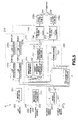
- the actual configuration of the speech synthesis unit is as shown in Fig.5, in which parts or components corresponding to those shown in Fig.4 are depicted by the same numerals.
- the LSP index data entering the input terminal 202, is sent to an inverse vector quantizer 231 for LSPs in the LPC parameter regenerating unit 213 so as to be inverse vector quantized into LSPs (line spectrum pairs) which are supplied to the parameter modification unit 5.
- the vector-quantized index data of the spectral envelope Am from the input terminal is sent to the inverse vector quantizer 212 for inverse vector quantization and turned into data of the spectral envelope which is sent to the parameter modification unit 5.
- the pitch data and the V/UV discrimination data from the input terminals 204, 205 are also sent to the parameter modification unit 5.
- To input terminals 207s and 207g of Fig.5 are supplied shape index data and gain index data as UV data from output terminals 107s and 107g of Fig.3 via period modification unit 3.
- the shape index data and the gain index data are thence supplied to the unvoiced speech synthesis unit 220.
- the shape index data from the terminal 207s and the gain index data from the terminal 207g are supplied to a noise codebook 221 and to a gain circuit 222 of the unvoiced speech synthesis unit 220, respectively.
- a representative value output read out from the noise codebook 221 is the noise signal component corresponding to the LPC residuals of the unvoiced speech and becomes an amplitude of a pre-set gain in the gain circuit 22.
- the resulting signal is supplied to the parameter modification unit 5.
- the parameter modification unit 5 interpolates the encoded parameters, outputted by the encoding unit 2 and having an output period modified by the period modification unit 3, for generating modified encoded parameters, which are supplied to the speech synthesis unit 6.
- the parameter modification unit 3 speed-modifies the encoded parameters. This eliminates the operation of speed modification after decoder outputting and enables the speech signals reproducing apparatus 1 to deal with fixed rates different with similar algorithms.
- the period modification unit 3 receives encoded parameters, such as LSPs, pitch, voiced/unvoiced (V/UV), spectral envelope Am or LPC residuals.
- LSPs, pitch, V/UV, Am and the LPC residuals are represented as l sp [n][p], P ch [n], vu v [n], am[n][k] and r es [n][i][j], respectively.
- the modified encoded parameters, ultimately calculated by the parameter modification unit 5, are represented as mod_ l sp [m][p], mod_ p ch [m], mod_ vu v [m], mod_ a m [m][k] and mod_ r es [m][i][j], where k and p denote the number of harmonics and the number of LSP orders, respectively.
- n and m denotes frame numbers corresponding to time-domain index data prior and subsequent to time axis conversion, respectively.
- each of n and m denotes an index of a frame having an interval of 20 msec
- i and j denote a sub-frame number and a sample number, respectively.
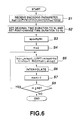
- the period modification unit 3 then sets the number of frames representing the original time duration to and the number of frames representing the time duration after modification to N 1 , N 2 , respectively, as shown at step S2.
- the parameter modification unit 5 sets m , corresponding to the frame number corresponding in turn to the index of the time axis after time axis modification, to 2.
- the parameter modification unit 5 finds two frames f r0 and f r1 and the differences left and right between the two frames f r0 and f r1 and the ratio m/spd.
- mod_ * [m] * [m/spd] where 0 ⁇ m ⁇ N 2 .
- m/spd is not an integer
- the encoded parameters for m/spd in Fig.7 may be found by interpolation as shown at step S6.
- mod_ * [m] * [f r0 ] ⁇ right + * [f r1 ] ⁇ left
- the parameter modification unit 5 changes the method for finding the encoded parameters depending on the voiced (V) or unvoiced (UV) character of the two frames f r0 and f r1 as indicated by steps S11 ff. of Fig.8.
- V/UV discrimination 1 and 0 denote voiced (V) and unvoiced (UV), respectively.
- step S11 If, at step S11, none of the two frames f r0 and f r1 is judged to be voiced (V), it is judged at step S13 whether both the two frames f r0 and f r1 are unvoiced (UV). If the result of judgment at step S13 is Yes, that is if the two frames are both unvoiced, the interpolation unit 5 slices 80 samples ahead and at back of r es , with m/spd as center and with p ch as a maximum value, as indicated at step S14.
- the interpolation unit 5 slices 80 samples ahead and at back of r es , centered about m/spd, to produce mod_ r es , as shown in Fig. 9B.
- step S13 processing transfers to step S15 where it is judged whether the frame f r0 is voiced (V) and the frame f r1 is unvoiced (UV). If the result of judgment is YES, that is if the frame f r0 is voiced (V) and the frame f r1 is unvoiced (UV), processing transfers to step S16. If the result of judgment is NO, that is if the frame f r0 is unvoiced (UV) and the frame f r1 is voiced (V), processing transfers to step S17.
- the two frames f r0 and f r1 are different as to V/UV, that is voiced (V) to unvoiced (UV).
- V voiced
- UV unvoiced
- step S16 If the result of judgment at step S16 is NO, left ⁇ right, so that the frame f r1 is closer, so that processing transfers to step S19 to maximize the pitch.
- step S18 processing transfers to step S18 to maximize the pitch.
- the interpolation unit 5 provides different operations for the interpolation of step S6 of Fig.6 shown in detail in Fig.8, depending on the V/UV character of the two frames f r0 and f r1 .
- processing transfers to step S6 for incrementing the value of m .
- the operations f steps S5 and S6 are repeated until the value of m becomes equal to N 2 .
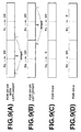
- the period modification unit 3 and the parameter modification unit 5 are explained collectively by referring to Fig.10.
- the period of the encoding parameters, extracted every 20 msec of a period by the encoding unit 2 is modified by the period modification unit 5 by time axis compression to 15 msec, as shown in Fig.10A.
- the parameter modification unit 5 calculates the modified encoded parameters every 20 msec, as shown in Fig.10C.
- the operations by the period modification unit 3 and the parameter modification unit 5 may be reversed in sequence, that is, the encoded parameters shown in Fig. 11 A are first interpolated as shown in Fig. 11B and subsequently compressed as shown in Fig. 11 C for calculating the modified encoded parameters.
- the modified encoded parameters mod l sp [m][p] on the LSP data, calculated by the parameter calculation unit 5, are sent to LSP interpolation circuits 232 v , 232 u for LSP interpolation.
- the resulting data is converted by LSP to ⁇ converting circuits 234 v , 234 uv for conversion into an ⁇ -parameter for linear predictive coding (LPC) which is sent to the LPC synthesis filter 214.
- LPC linear predictive coding
- the LSP interpolation circuit 232 v and the LSP to ⁇ converting circuit 234 v are used for the voiced (V) signal portion, while the LSP interpolation circuit 232 u and the LSP to ⁇ converting circuit 234 u are used for the unvoiced (UV) signal portion.
- the LPC synthesis filter 214 is made up of an LPC synthesis filter 236 for the voiced portion and an LPC synthesis filter 237 for the unvoiced portion.
- the LPC coefficient interpolation is performed independently for the voiced portion and the unvoiced portion for preventing ill effects otherwise produced by interpolation of LSPs of totally different character at a transient region from the voiced portion to the unvoiced portion or at a transient region from the voiced portion to the unvoiced portion.
- the modified encoded parameter on the spectral envelope data mod_ a m [m][k], as found by the parameter modification unit 5, is sent to a sinusoidal synthesis circuit 215 of the voiced speech synthesis unit 211.
- This voiced speech synthesis unit 211 is also fed with the modified encoded parameter on the pitch mod_ p ch [m] and the modified encoded parameter mod_ vu v [m] on the V/UV decision data, as calculated by the parameter modification unit 5.
- the sinusoidal synthesis circuit 215 From the sinusoidal synthesis circuit 215, the LPC residual data corresponding to the output of the LPC inverted filter 111 of Fig.3 are taken out and sent to an adder 218.
- the modified encoded parameter on the spectral envelope data mod_ a m [m][k], modified encoded parameter on the pitch mod_p ch [m] and the modified encoded parameter on the V/UV decision data mod vu u [m], as found by the parameter modification unit 5, are sent to a noise synthesis circuit 216 for noise addition for the voiced (V) portion.
- An output of the, noise synthesis circuit 216 is sent to an adder 218 via a weighted overlap-and-add circuit 217.
- the noise taking into account the parameters derived from the encoded speech data such as pitch spectral envelope amplitudes, maximum amplitude in the frame or residual signal level, is added to the voiced portion of the LPC residual signal of the LPC synthesis filter input, that is excitation, in consideration that, if the input to the LPC synthesis filter of the voiced speech, that is excitation, is produced by sinusoidal synthesis, "stuffed" feeling is produced in the low-pitch sound, such as male speech, while the sound quality is rapidly changed between the V and UV speech portions, thus producing an non-spontaneous feeling.
- the parameters derived from the encoded speech data such as pitch spectral envelope amplitudes, maximum amplitude in the frame or residual signal level
- a sum output of the adder 218 is sent to the synthesis filter 236 for the voiced speech where the time waveform data is produced by LPC synthesis.
- resulting time waveform data is filtered by a post-filter 238v and thence supplied to an adder 239.
- the LPC synthesis filter 214 is separated into the synthesis filter for V 236 and the synthesis filter for UV 237, as explained previously. If the synthesis filter is not separated in this manner, that is if the LSPs are interpolated continuously every 20 samples or every 2.5 msec without making distinction between the V and UV signal portions, the LSPs of totally different character are interpolated at the U to UV to UV to V transient portions, thus producing foreign sound. For preventing such ill effects, the LPC synthesis filter is separated into the filter for V and the filter for UV for interpolating the LPC coefficients independently for V and UV.
- the modified encoded parameters on the LPC residuals mod r es [m][i][j], as calculated by the parameter modification unit 5, are sent to the windowing circuit 223 for windowing for smoothing the junction portions with the voiced speech portion.
- An output of the windowing circuit 223 is sent to the synthesis filter 237 for UV of the LPC synthesis filter 214 as an output of the unvoiced speech synthesis unit 220.
- the synthesis filter 237 performs LPC synthesis on the data to provide time waveform data for the unvoiced portion which is filtered by a post-filter for unvoiced speech 238u and thence supplied to an adder 239.
- the adder 239 adds the time waveform signal of the voiced portion from the post-filter 238v for voiced speech to the time waveform data for the unvoiced speech portion from the post-filter for the unvoiced speech portion 238u and outputs the resulting data at an output terminal 201.
- an array of modified encoded parameters mod_ *[m], where 0 ⁇ m ⁇ N 2 is decoded in this manner instead of the inherent array * [n], where 0 ⁇ n ⁇ N 1 .
- the frame interval during decoding may be fixed such as at 20 msec as conventionally. In such case, time axis compression and resulting speed-up of the reproducing rate may be realized for N 2 ⁇ N 1 , while time axis expansion and resulting speed-down of the reproducing rate may be realized for N 2 > N 1 .
- the ultimately obtained parameter string is arrayed in an inherent spacing of 20 msec for decoding, so that optional speed-up may be realized easily. Moreover, speed-up and speed-down may be realized without any distinction by the same processing operation.
- the contents of solid-state recording can be reproduced at a speed twice the real-time speed. Since the pitch and the phoneme remain unchanged despite increased playback speed, the recording contents can be discerned despite reproduction at a significantly increased playback speed.
- N 2 ⁇ N 1 that is if the playback speed is lowered, the playback sound tends to become non-spontaneous since plural parameters mod_ r es are produced from the same LPC residuals r es in the case of the unvoiced frame.
- an appropriate amount of noise may be added to the parameters mod_ r es for eliminating such non-spontaneousness to some extent.
- the parameters mod_ r es may be replaced by suitably generated Gaussian noise, or the excitation vector, randomly selected from the codebook, may also be employed.
- the time axis of the output period of the encoded parameters from the encoding unit 2 is compressed by the period modification unit 3 for speed-up of the reproducing speed.
- the frame length may be rendered variable by the decoding uni5t 4 for controlling the reproducing speed.
- the frame number n is not changed before and after parameter generation by the parameter modification unit 5 of the decoding unit 4.
- the parameter modification unit 5 modifies the parameters l sp [n][p] and vu v [n] to mod_ l sp [n][p] and to mod _ vu v [n], respectively, regardless of whether the frame in subject is voiced or unvoiced.
- mod_ vu v [n] is 1, that is if the frame in subject is voiced (V)
- the parameters p ch [n] and a m [n][k] are modified to mod_ p ch [n] and to mod_ a m [n][k], respectively.
- mod_ vu v [n] is 0, that is if the frame in subject is unvoiced (UV)
- the parameter r es [n][i][j] is modified to mod_ r es [n][i][j].
- the parameter modification unit 5 directly modifies l sp [n][p], p ch [n], vu v [n] and a m [n][k] directly to mod_ l sp [n][p], p ch [n], mod vu v [n] and to mod_ a m [n][k]. However, the parameter modification unit varies the residual signal mod_ r es [n][i][j] depending on the speed spd.
- the residual signals of the original signal are sliced at a mid portion, as shown in Fig.12. If the original frame length is orgFrmL, (orgFrmL - frmL)/2 ⁇ j ⁇ (orgFrmL + frmL)/2 is sliced from the original frame r es [n][i] to give mod_ r es [n][i]. It is also possible that slicing be made at the leading end of the original frame.
- the original frame is used and an original frame added to with noise components is used for any deficit portion.
- a decoded excitation vecto added to with a suitably generated noise may also be used.
- the Gaussian noise may be generated and used as the excitation vector for reducing the alien feeling produced by continuation of frames of the same waveform.
- the above noise components may also be added to both ends of the original frame.
- the speech synthesis unit 6 is constructed and designed so that the LSP interpolation unit 232v and 232u, sinusoidal synthesis unit 215 and the windowing unit 223 will perform different operations for controlling the speed by time axis compansion.
- the LSP interpolation unit 232 v finds the smallest integer p satisfying the relation frmL/p ⁇ 20 if the frame in subject is voiced (V).
- the LSP interpolation unit 232 u finds the smallest integer p satisfying the relation frmL/p ⁇ 80 if the frame in subject is voiced (UV).
- the range of the sub-frame subl[i][j] for LSP interpolation is determined by the following equation: nint(frmL/p ⁇ i) ⁇ j ⁇ nint(frmL/p ⁇ (i+1), where 0 ⁇ i ⁇ p-1.
- nint(x) is a function which returns an integer closest to x by rounding the first sub-decimal order.
- p 1 if frmL is less than 20 or 80.
- LSPs are interpolated at a rate of frmL ⁇ (2p - 2i - 1)/(20:frmL ⁇ (2i + 1)/2p, as disclosed in our copending JP Patent Application No.6-198451.
- the number of the sub-frames may be fixed and the LSPs of each sub-frame may be interpolated at all times at the same ratio.
- the sinusoidal synthesis unit 223 modifies the window length for matching to the frame length frmL.
- the encoded parameters, the output period of which has been companded on the time axis, are modified using the period modification unit 3 and the parameter modification unit 5 for varying the reproducing speed without changing the pitch or phoneme.
- the parts and components corresponding to those shown in Fig.4 are indicated by the same reference numerals.
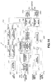
- the basic concept underlying the decoding unit 8 is to convert the basic frequency of the harmonics of the encoded speech data entered from the encoding unit 2 and the number of amplitude data in a pre-set band by the number of data conversion unit 270 operating as data conversion means to perform only the pitch without changing the phoneme.
- the number of data conversion unit 270 varies the pitch by modifying the number of data specifying the size of spectral components in each input harmonics.
- a vector quantized output of LSPs corresponding to an output of the output terminal 102 of Figs.2 and 3, or codebook indices, are supplied to the input terminal 202.
- the LSP index data is sent to an inverse vector quantizer 231 of the LPC parameter reproducing unit 213 for inverse vecto quantization to line spectrum pairs (LSPs).
- the LSPs are sent to LSP interpolation circuits 232, 233 for interpolation and thence supplied to LSP to ⁇ conversion circuits 234, 235 for conversion to ⁇ -parameters of the linear prediction codes. These ⁇ -parameters are sent to the LPC synthesis filter 214.
- the LSP interpolation circuit 232 and the LSP to ⁇ converting circuit 234 are used for the voiced (V) signal portion, while the LSP interpolation circuit 233 and the LSP to ⁇ converting circuit 235 are used for the unvoiced (UV) signal portion.
- the LPC synthesis filter 214 is made up of an LPC synthesis filter 236 for the voiced portion and an LPC synthesis filter 237 for the unvoiced portion. That is, the LPC coefficient interpolation is performed independently for the voiced portion and the unvoiced portion for preventing ill effects otherwise produced by interpolation of LSPs of totally different character at a transient region from the voiced portion to the unvoiced portion or at a transient region from the voiced portion to the unvoiced portion.
- To an input terminal 203 of Fig.14 is supplied weighted vector quantized code index data of the spectral envelope Am corresponding to an output of the terminal 103 of the encoder shown in Figs.2 and 3.
- To an input terminal 205 is supplied V/UV decision data from the terminal 105 of Figs.2 and 3.
- the vector quantized index data of the spectral envelope Am from the input terminal 203 is sent to the inverse vector quantizer 212 for inverse vector quantization.
- the number of amplitude data of the inverse vector quantized envelope is fixed at a pre-set value of, for example, 44. Basically, the number of data is converted to give the number of harmonics corresponding to the pitch data. If it is desired to change the pitch, as in the present embodiment, the envelope data from the inverse vector quantizer 212 is sent to the number of data conversion unit 270 for varying the number of amplitude data by, for example, interpolation, depending on the desired pitch value.
- the number of data conversion unit 270 is also fed with pitch data from the input terminal 204 such that the pitch at the encoding time is changed to a desired pitch which is outputted.
- the amplitude data and the modified pitch data are sent to the sinusoidal synthesis circuit 215 of the voiced speech synthesis unit 211.
- the number of the amplitude data supplied to the synthesis circuit 215 corresponds the modified pitch of the spectral envelope of the LPC residuals from the number of data conversion unit 270.
- interpolation methods for converting the number of amplitude data of the spectral envelope of the LPC residuals by the number of data conversion unit 270.
- a suitable number of dummy data for interpolating amplitude data of an effective band block on the frequency axis from the last amplitude data in the block as far as the first amplitude data in the block or dummy data extending the left-hand end (first data) and the right-hand end (last data) in the block are appended to the amplitude data in the block, for enhancing the number of data to N F .
- an Os-tuple number of amplitude data are found by band-limiting type Os-tuple oversampling, such as octatuple oversampling.
- the Os-tuple number of the amplitude data ((mMx + 1) ⁇ Os number of data) is further expanded to a larger number of N M , such as 2048, by linear interpolation.
- This N M number data is converted into the pre-set number M (such as 44) by decimation and vector quantization is then carried out on the pre-set number of data.
- the pitch frequency F 0 8000/L
- n L/2 harmonics set up to 4000 Hz.
- the number of harmonics is (L/2) ⁇ (3400/4000). This is converted by the above data number conversion or dimensional conversion to, for example, 44, before proceeding to vector quantization. There is no necessity of performing quantization if simply the pitch is to be varied.
- the number of 44 of the harmonics can be changed to a desired number, that is to a desired pitch frequency Fx, by dimensional conversion by the number of data conversion unit 270.
- the frame-to-frame difference is found at the time of encoding prior to vector quantization of spectral data, the frame-to-frame difference is decoded after the inverse vector quantization. The number of data conversion is then performed for producing spectral envelope data.
- the sinusoidal synthesis circuit 215 is supplied not only with pitch data and spectral envelope amplitude data of LPC residuals from the number of data conversion unit 270, but also with the V/UV decision data from the input terminal 205. From the sinusoidal synthesis circuit 215, the LPC residual data are taken out and sent to the adder 218.
- the envelope data from the inverse vector quantizer 212, the pitch data from the input terminal 204 and the V/UV decision data frm the input terminal 205 are sent to the noise addition circuit 216 for noise addition for the voiced (V) portion.
- the noise taking into account the parameters derived from the encoded speech data, such as pitch spectral envelope amplitudes, maximum amplitude in the frame or residual signal level, is added to the voiced portion of the LPC residual signal for the LPC synthesis filter input, that is excitation, in consideration that, if the input to the LPC synthesis filter of the voiced speech, that is excitation, is produced by sinusoidal synthesis, "stuffed" feeling is produced in the low-pitch sound, such as male speech, while the sound quality is rapidly changed between the V and UV speech portions thus producing an non-spontaneous feeling.
- a sum output of the adder 218 is sent to the synthesis filter 236 for the voiced speech where the time waveform data is produced by LPC synthesis.
- resulting time waveform data is filtered by a post-filter 238v for voiced data and thence supplied to an adder 239.
- To input terminals 207s and 207g of Fig.14 are supplied shape index data and gain index data as UV data from output terminals 107s and 107g of Fig.3 via period modification unit 3.
- the shape index data and the gain index data are thence supplied to the unvoiced speech synthesis unit 220.
- the shape index data from the terminal 207s and the gain index data from the terminal 207g are supplied to a noise codebook 221 and a gain circuit 222 of the unvoiced speech synthesis unit 220, respectively.
- a representative value output read out from the noise codebook 221 is the noise signal component corresponding to the LPC residuals of the unvoiced speech and becomes an amplitude of a pre-set gain in the gain circuit 222.
- the representative value output of the pre-set gain amplitude is sent to a windowing circuit 223 for windowing for smoothing a junction portion to the voiced signal portion.
- An output of the windowing circuit 223 is sent as an output of the unvoiced speech synthesis unit 220 to a synthesis filter 237 for unvoiced (UV) portion of the LPC synthesis filter 214.
- the output of the windowing circuit 223 is processed by the synthesis filter 237 by LPV synthesis to give time-domain waveform signals of the unvoiced speech signal portion which is then filtered by a post-filter for unvoiced speech portion 238u and thence supplied to the adder 239.
- the adder 239 sums the time-domain waveform signal for the voiced speech signal portion from the post-filter 238v for the voiced speech to the time-domain waveform data for the unvoiced speech signal portion from the post-filter for the unvoiced speech signal portion 238u.
- the resulting sum signal is outputted at the output terminal 201.
- the pitch can be varied without changing the phoneme of the speech by changing the number of harmonics without changing the shape of the spectral envelope.
- its pitch may be optionally varied for synthesis.
- an encoded bitstream or encoded data obtained on encoding by the encoder of Figs.2 and 3, are outputted by an encoded data outputting unit 301.
- at least the pitch data and spectral envelope data are sent via a data conversion unit 302 to a waveform synthesis unit 303.
- the data irrelevant to pitch conversion, such as voiced/unvoiced (V/UV) decision data, are directly sent to the waveform synthesis unit 303.
- the waveform synthesis unit 303 synthesizes the speech waveform based on the spectral envelope data or pitch data.
- LSP data or CELP data are also taken out from the outputting unit 301 and supplied as described above.
- At least pitch data or spectral envelope data are converted by the data conversion unit 302 depending on the desired pitch as described above and thence supplied to the waveform synthesis unit 303 where the speech waveform is synthesized from the converted data.
- the speech signals changed in pitch without changing the phoneme can be taken out at an output terminal 304.
- the above-described technique can be used for synthesis of speech by rule or text.
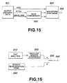
- Fig.16 shows an example of application of the present invention to speech text synthesis.
- the above-described decoder for speech encoding for compression may be used simultaneously as a text speech synthesizer.
- regeneration of speech data is used in combination.
- the speech rule synthesizer and the speech synthesizer with data conversion for pitch modification as described above are comprised in a speech-by-rule synthesis unit 300.
- Data from a text analysis unit 310 is supplied to the speech-by-rule synthesis unit 300 from which the synthesized speech having the desired pitch is outputted and sent to a fixed contact a of a changeover switch 330.
- a speech reproducing unit 320 reads out speech data occasionally compressed and stored in a memory such as ROM and decodes the data for expansion. The decoded data is sent to the other fixed contact b of the changeover switch 330.
- One of the synthesized speech signals and the reproduced speech signals is selected by the changeover switch 330 and outputted at an output terminal 340.
- the device shown in Fig.16 may be used in, for example, a navigation system for a vehicle.
- the reproduced speech of high quality and high clarity from the speech regenerator 320 may be used for routine speech, such as "Please turn to right" for bearing indication, while the synthesized speech from the speech-by-rule generator 300 may be used for speech of special designations for e.g. a building or territory, which is voluminous and cannot be stored as speech information in a ROM.
- the present invention has an additional merit that the same hardware may be used for the computer speech synthesizer 300 and the speech regenerator 320.
- the present invention is not limited to the above-described embodiments.
- the construction of the speech analysis side (encoder) of Figs.1 and 3 or the speech synthesis side (decoder) of Fig.14, described above as hardware may be realized by a software program using, for example, a digital signal processor (DSP).
- DSP digital signal processor
- the data of plural frames may be handled together and quantized by matrix quantization in place of vector quantization.
- the present invention may also be applied to a variety of speech analysis/synthesis methods.
- the present invention is also not limited to transmission or recording/reproduction and may be applied to a variety of usages such as pitch conversion, speed or rate conversion, synthesis of the speech-by-rule or noise suppression.
- the above-described signal encoding and signal decoding apparatus may be used as a speech codec employed in, for example, a portable communication terminal or a portable telephone set shown in Fig.14.
- Fig.17 shows a transmitting side of a portable terminal employing a speech encoding unit 160 configured as shown in Figs.2 and 3.
- the speech signals collected by a microphone 161 are amplified by an amplifier 162 and converted by an analog/digital (A/D) converter 163 into digital signals which are sent to the speech encoding unit 160 configured as shown in Figs. 1 and 3.
- the digital signals from the A/D converter 163 are supplied to the input terminal 101.
- the speech encoding unit 160 performs encoding as explained in connection with Figs. 1 and 3.
- Output signals of output terminals of Figs.1 and 2 are sent as output signals of the speech encoding unit 160 to a transmission channel encoding unit 164 which then performs channel coding on the supplied signals.
- Output signals of the transmission channel encoding unit 164 are sent to a modulation circuit 165 for modulation and thence supplied to an antenna 168 via a digital/analog (D/A) converter 166 and an
- Fig.18 shows a reception side of a portable terminal employing a speech decoding unit 260 configured as shown in Figs.5 and 14.
- the speech signals received by the antenna 261 of Fig.14 are amplified an RF amplifier 262 and sent via an analog/digital (A/D) converter 263 to a demodulation circuit 264, from which demodulated signals are sent to a transmission channel decoding unit 265.
- An output signal of the decoding unit 265 is supplied to a speech decoding unit 260 configured as shown in Figs.5 and 14.
- the speech decoding unit 260 decodes the signals as explained in connection with Figs.5 and 14.
- An output signal at an output terminal 201 of Figs.2 and 4 is sent as a signal of the speech decoding unit 260 to a digital/analog (D/A) converter 266.
- An analog speech signal from the D/A converter 266 is sent to a speaker 268.
Abstract
Description
- This invention relates to a method and apparatus for reproducing speech signals at a controlled speed.
- There have hitherto been known a variety of encoding methods for encoding an audio signal (inclusive of speech and acoustic signals) for compression by exploiting statistic properties of the signals in the time domain and in the frequency domain and psychoacoustic characteristics of the human ear. The encoding method may roughly be classified into time-domain encoding, frequency domain encoding and analysis/synthesis encoding.
- Examples of the high-efficiency encoding of speech signals include sinusoidal analysis encoding, such as harmonic encoding, multi-band excitation (MBE) encoding, sub-band coding (SBC), linear predictive coding (LPC), discrete cosine transform (DCT), modified DCT (MDCT) and fast Fourier transform (FFT).
- Meanwhile, the high-efficiency speech encoding method by the time-axis processing, as typified by code excited linear prediction (CELP) encoding, involves difficulties in expeditious time-axis conversion (modification) because of the necessity of performing voluminous processing operations subsequent to decoder outputting. Moreover, since speed control is performed in the time domain subsequent to decoding, the method cannot be used for bit rate conversion.
- On the other hand, if it is attempted to decode speech signals encoded by the above encoding methods, it is frequently desired to vary only the pitch without changing the phoneme of the speech. However, with the usual speech decoding method, the decoded speech has to be pitch-converted using pitch control, thus complicating the structure and raising the cost.
- It is therefore an object of the present invention to provide a method and apparatus for reproducing speech signals whereby speed control to a desired rate over a wide range may be achieved with a high sound quality without changing the phoneme or pitch.
- It is another object of the present invention to provide a method and apparatus for decoding the speech and a method and apparatus for synthesizing the speech whereby pitch conversion or pitch control can be achieved by a simplified structure.
- It is yet another object of the present invention whereby the pitch-converted or pitch-controlled speech signals can be transmitted or received by a simplified structure.
- With the speech signal reproducing method according to the present invention, the input speech signal is divided on the time axis in terms of pre-set encoding units to produce encoded parameters which are interpolated to produce modified encoded parameters for desired time points, and the speech signal is reproduced based on these modified encoded parameters.
- With the speech signal reproducing apparatus according to the present invention, the input speech signal is divided on the time axis in terms of pre-set encoding units to produce encoded parameters which are interpolated to modified encoded parameters for desired time points, and the speech signal is then reproduced based on these modified encoded parameters.
- With the speech signal reproducing method, the speech is reproduced with a block length differing from that used for encoding, using encoded parameters obtained on dividing the input speech signal on the time axis in terms of pre-set block as units and encoding the divided speech signal in terms of the encoding blocks.
- With the speech decoding method and apparatus according to the present invention, the fundamental frequency and the number in a pre-set band of harmonics of the input encoded speech data are converted and the, number of data specifying the amplitude of a spectral component in each input harmonics is interpolated for modifying the pitch.
- The pitch frequency is modified at the time of encoding by dimensional conversion in which the number of harmonics is set at a pre-set value.
- In this case, the decoder for speech compression may be used simultaneously as a speech synthesizer for text speech synthesis. For routine speech pronunciation, clear playback speech is obtained by compression and expansion, whereas, for special speech synthesis, text synthesis or synthesis under the pre-determined rule is used for constituting an efficient speech output system.
- With the speech signal reproducing method and apparatus according to the present invention, an input speech signal is divided in terms of pre-set encoding units on the time axis and encoded in terms of the encoding unit in order to find encoded parameters which are then interpolated to find modified encoded parameters for desired time points. The speech signal is then reproduced based on the modified encoded parameters, so that speed control over a wide range may be realized easily with high quality without changing the phoneme or pitch.
- With the speech signal reproducing method and apparatus according to the present invention, the speech is reproduced with a block length differing from that used for encoding, using encoded parameters obtained on dividing the input speech signal on the time axis in terms of pre-set block as units and on encoding the divided speech signal in terms of the encoding blocks. The result is that speed control over a wide range may be realized easily with high quality without changing the phoneme or pitch.
- With the speech decoding method and apparatus according to the present invention, the fundamental frequency and the number in a pre-set band of harmonics of the input encoded speech data are converted and the number of data specifying the amplitude of a spectral component in each input harmonics is interpolated for modifying the pitch. The result is that the pitch may be changed to a desired value by a simplified structure.
- In this case, the decoder for speech compression may be used simultaneously as the speech synthesizer for text speech synthesis. For routine speech pronunciation, clear playback speech is obtained by compression and expansion, whereas, for special speech synthesis, text synthesis or synthesis under rule is used for constituting an efficient speech output system.
- With the portable radio terminal apparatus, the pitch-converted to pitch-controlled speech signals can be transmitted or received by a simplified structure.
- The present invention will be more clearly understood from the following description, given by way of example only, with reference to the accompanying drawings in which:
- Fig. 1 is a block diagram showing a basic structure of a speech signal reproducing method and a speech signal reproducing apparatus for carrying out the speech signal reproducing method according to the present invention.
- Fig.2 is a schematic block diagram showing an encoding unit of the speech signal reproducing apparatus shown in Fig. 1.
- Fig.3 is a block diagram showing a detailed structure of the encoding unit.
- Fig.4 is a schematic block diagram showing the structure of a decoding unit of the speech signal reproducing apparatus shown in Fig.1.
- Fig.5 is a block diagram showing a detailed structure of the decoding unit.
- Fig.6 is a flowchart for illustrating the operation of a unit for calculating modified encoding parameters of the decoding unit.
- Fig.7 schematically illustrates the modified encoding parameters obtained by the modified encoding parameter calculating unit on the time axis.
- Fig.8 is a flowchart for illustrating the detailed interpolation operation performed by the modified encoding parameter calculating unit.
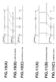
- Figs.9A to 9D illustrates the interpolation operation.
- Figs. 10A to 10C illustrate typical operations performed by the unit for calculating modified encoding parameters.
- Figs.11A to 11C illustrate other typical operations performed by the unit for calculating modified encoding parameters.
- Fig. 12 illustrates an operation in case the frame length is rendered variable to control the speed quickly by the decoding unit.
- Fig. 13 illustrates an operation in case the frame length is rendered variable to control the speed slowly by the decoding unit.
- Fig. 14 is a block diagram showing another detailed structure of the decoding unit.
- Fig.15 is a block diagram showing an example of application to a speech synthesis device.
- Fig.16 is a block diagram showing an example of application to a text speech synthesis device.
- Fig.17 is a block diagram showing the structure of a transmitter of a portable terminal employing the encoding unit.
- Fig. 18 is a block diagram showing the structure of a receiver of a portable terminal employing the decoding unit.
-
- Referring to the drawings, the speech signal reproducing method and apparatus according to a preferred embodiment of the present invention will be explained. The present embodiment is directed to a speech signal reproducing apparatus 1 for reproducing speech signals based on encoding parameters as found by dividing the input speech signals on the time axis in terms of a pre-set number of frames as encoding units and encoding the divided input speech signals, as shown in Fig. 1.
- The speech signal reproducing apparatus 1 includes an encoding unit 2 for encoding the speech signals entering an input terminal 101 in terms of frames as units for outputting encoded parameters such as linear prediction encoding (LPC) parameters, line spectrum pair (LSP) parameters, pitch, voiced (V)/unvoiced (UV) or spectral amplitudes Am, and a period modification unit 3 for modifying an output period of the encoding parameters by time axis compansion. The speech signal reproducing apparatus also includes a decoding unit 4 for interpolating the encoded parameters outputted at the period modified by the period modification unit 3 for finding the modified encoded parameters for desired time points and for synthesizing the speech signals based on the modified encoded parameters for outputting the synthesized speech signals at an output terminal 201.
- The encoding unit 2 is explained by referring to Figs.2 and 3. The encoding unit 2 decides, based on the results of discrimination, whether the input speech signal is voiced or unvoiced, and performs sinusoidal synthetic encoding for a signal portion found to be voiced, while performing vector quantization by a closed-loop search of the optimum vector using an analysis-by-synthesis method for a signal portion found to be unvoiced, for finding the encoded parameters. That is, the encoding unit 2 includes a first encoding unit 110 for finding short-term prediction residuals of the input speech signal, such as linear prediction coding (LPC) residuals, to perform sinusoidal analysis encoding, such as harmonic encoding, and a second encoding unit 120 for performing waveform coding by transmitting phase components of the input speech signal. The first encoding unit 110 and the second encoding unit 120 are used for encoding the voiced (V) portion and the unvoiced (UV) portion, respectively.
- In the embodiment of Fig.2, the speech signal supplied to the input terminal 101 is sent to an inverted LPC filter 111 and an LPC analysis quantization unit 113 of the first encoding unit 110. The LPC coefficient obtained from the LPC analysis/quantization unit 113 or the so-called α-parameter is sent to the inverted LPC filter 111 for taking out the linear prediction residuals (LPC residuals) of the input speech signal by the inverse LPC filter 111. From the LPC analysis/quantization unit 113, a quantized output of the linear spectral pairs (LSP) is taken out as later explained and sent to an output terminal 102. The LPC residuals from the inverted LPC filter 111 are sent to a sinusoidal analysis encoding unit 114. The sinusoidal analysis encoding unit 114 performs pitch detection, spectral envelope amplitude calculations and V/UV discrimination by a voiced (V)/ unvoiced (UV) discrimination unit 115. The spectral envelope amplitude data from the sinusoidal analysis encoding unit 114 are sent to the vector quantization unit 116. The codebook index from the vector quantization unit 116, as a vector-quantized output of the spectral envelope, is sent via a switch 117 to an output terminal 103, while an output of the sinusoidal analysis encoding unit 114 is sent via a switch 118 to an output terminal 104. The V/UV discrimination output from the V/UV discrimination unit 115 is sent to an output terminal 105 and to the switches 117, 118 as switching control signals. For the voiced (V) signal, the index and the pitch are selected so as to be taken out at the output terminals 103, 104. For vector quantization at the vector quantizer 116, a suitable number of dummy data for interpolating amplitude data of an effective band block on the frequency axis from the last amplitude data in the block as far as the first amplitude data in the block, or dummy data extending the last data and the first data in the block, are appended to the trailing end and to the leading end of the block, for enhancing the number of data to NF. Then, an Os-tuple number of amplitude data are found by band-limiting type Os-tuple oversampling, such as octatuple oversampling. The Os-tuple number of the amplitude data ((mMx + 1) × Os number of data) is further expanded to a larger number of NM, such as 21048, by linear interpolation. This NM number data is converted into the pre-set number M (such as 44) by decimation and vector quantization is then performed on the pre-set number of data.
- In the present embodiment, the second encoding unit 120 has a code excited linear predictive (CELP) coding configuration and performs vector quantization on the time-domain waveform by a closed-loop search employing an analysis-by-synthesis method. Specifically, an output of a noise codebook 121 is synthesized by a weighted synthesis filter 122 to produce a weighted synthesized speech which is sent to a subtractor 123 where an error between the weighted synthesized speech and the speech supplied to the input terminal 101 and subsequently processed by a perceptually weighting filter 125 is found. A distance calculation circuit 124 calculates the distance and a vector which minimizes the error is searched in the noise codebook 121. This CELP encoding is used for encoding the unvoiced portion as described above. The codebook index as the UV data from the noise codebook 121 is taken out at an output terminal 107 via a switch 127 which is turned on when the results of V/UV discrimination from the V/UV discrimination unit 115 indicates an unvoiced (UV) sound.
- Referring to Fig. 3, a more detailed structure of a speech signal encoder shown in Fig. 1 is now explained. In Fig.3, the parts or components similar to those shown in Fig. 1 are denoted by the same reference numerals.
- In the speech signal encoder 2 shown in Fig.3, the speech signals supplied to the input terminal 101 are filtered by a high-pass filter 109 for removing signals of an unneeded range and thence supplied to an LPC analysis circuit 132 of the LPC analysis/quantization unit 113 and to the inverse LPC filter 111.
- The LPC analysis circuit 132 of the LPC analysis/ quantization unit 113 applies a Hamming window, with a length of the input signal waveform on the order of 256 samples as a block, and finds linear prediction coefficients, that is so-called α-parameters, by the self-correlation method. The framing interval as a data outputting unit is set to approximately 160 samples. If the sampling frequency fs is 8 kHz, for example, a one-frame interval is 20 msec or 160 samples.
- The α-parameters from the LPC analysis circuit 132 are sent to an α-LSP conversion circuit 133 for conversion into line spectra pair (LSP) parameters. This converts the α-parameters, as found as direct type filter coefficients, into for example, ten, that is five pairs of the LSP parameters. This conversion is carried out by, for example, the Newton-Rhapson method. The reason the α-parameters are converted into the LSP parameters is that the LSP parameters are superior in interpolation characteristics to the α-parameters.
- The LSP parameters from the α-LSP conversion circuit 133 are matrix- or vector-quantized by the LSP quantizer 134. It is possible to take a frame-to-frame difference prior to vector quantization, or to collect plural frames together in order to perform matrix quantization. In the present case, the LSP parameters, calculated every 20 msec, are vector-quantized, with 20 msec as a frame.
- The quantized output of the quantizer 134, that is the index data of the LSP quantization, are taken out to the decoding unit 103 at a terminal 102, while the quantized LSP vector is sent to an LSP interpolation circuit 136.
- The LSP interpolation circuit 136 interpolates the LSP vectors, quantized every 20 msec or 40 msec, in order to provide an octatuple rate. That is, the LSP vector is updated every 2.5 msec. The reason is that, if the residual waveform is processed with the analysis/synthesis by the harmonic encoding/decoding method, the envelope of the synthetic waveform presents an extremely sooth waveform, so that, if the LPC coefficients are changed abruptly every 20 msec, a foreign noise is likely to be produced. That is, if the LPC coefficient is changed gradually every 2.5 msec, such foreign noise may be prevented from being produced.
- For inverted filtering of the input speech using the interpolated LSP vectors, produced every 2.5 msec, the LSP parameters are converted by an LSP to α conversion circuit 137 into α-parameters as coefficients of, for example, ten-order direct type filter. An output of the LSP to α conversion circuit 137 is sent to the LPC inverted filter circuit 111 which then performs inverted filtering for producing a smooth output using α-parameters updated every 2.5 msec. An output of the inverted LPC filter 111 is sent to an orthogonal transform circuit 145, such as a DCT circuit, of the sinusoidal analysis encoding unit 114, such as a harmonic encoding circuit.
- The α-parameters from the LPC analysis circuit 132 of the LPC analysis/quantization unit 113 are sent to a perceptual weighting filter calculating circuit 139 where data for perceptual weighting is found. These weighting data are sent to the perceptual weighting vector quantizer 116, perceptual weighting filter 125 of the second encoding unit 120 and to the perceptual weighted synthesis filter 122.
- The sinusoidal analysis encoding unit 114 of the harmonic encoding circuit analyzes the output of the inverted LPC filter 111 by a method of harmonic encoding. That is, pitch detection, calculations of the amplitudes Am of the respective harmonics and voiced (V)/ unvoiced (UV) discrimination, are carried out, and the numbers of the amplitudes Am or the envelopes of the respective harmonics, varied with the pitch, are made constant by dimensional conversion.
- In an illustrative example of the sinusoidal analysis encoding unit 114 shown in Fig.3, commonplace harmonic encoding is used. In particular, in multi-band excitation (MBE) encoding, it is assumed in modelling that voiced portions and unvoiced portions are present in the frequency area or band at the same time point (in the same block or frame). In other harmonic encoding techniques, it is uniquely judged whether the speech in one block or in one frame is voiced or unvoiced. In the following description, a given frame is judged to be UV if the totality of the band is UV, insofar as the MBE encoding is concerned.
- The open-loop pitch search unit 141 and the zero-crossing counter 142 of the sinusoidal analysis encoding unit 114 of Fig.3 is fed with the input speech signal from the input terminal 101 and with the signal from the high-pass filter (HPF) 109, respectively. The orthogonal transform circuit 145 of the sinusoidal analysis encoding unit 114 is supplied with LPC residuals or linear prediction residuals from the inverted LPC filter 111. The open loop pitch search unit 141 takes the LPC residuals of the input signals to perform relatively rough pitch search by open loop. The extracted rough pitch data is sent to a fine pitch search unit 146 by closed loop search as later explained. From the open loop pitch search unit 141, the maximum value of the normalized autocorrelation r(p), obtained by normalizing the maximum value of the self-correlation, of the LPC residuals along with the rough pitch data, are taken out along with the rough pitch data so as to be sent to the V/UV discrimination unit 115.
- The orthogonal transform circuit 145 performs orthogonal transform, such as discrete Fourier transform (DFT), for converting the LPC residuals on the time axis into spectral amplitude data on the frequency axis. An output of the orthogonal transform circuit 145 is sent to the fine pitch search unit 146 and a spectral evaluation unit 148 for evaluating the spectral amplitude or envelope.
- The fine pitch search unit 146 is fed with relatively rough pitch data extracted by the open loop pitch search unit 141 and with frequency-domain data obtained by DFT by the orthogonal transform unit 145. The fine pitch search unit 146 swings the pitch data by ± several samples, at a rate of 0.2 to 0.5, centered about the rough pitch value data, in order to arrive ultimately at the value of the fine pitch data having an optimum decimal point (floating point). The analysis by synthesis method is used as the fine search technique for selecting a pitch so that the power spectrum will be closest to the power spectrum of the original sound. Pitch data from the closed-loop fine pitch search unit 146 is sent to an output terminal 104 via a switch 118.
- In the spectral evaluation unit 148, the amplitude of each harmonics and the spectral envelope as the sum of the harmonics are evaluated based on the spectral amplitude and the pitch as the orthogonal transform output of the LPC residuals and sent to the fine pitch search unit 146, V/UV discrimination unit 115 and to the perceptually weighted vector quantization unit 116.
- The V/UV discrimination unit 115 discriminates V/UV of a frame based on an output of the orthogonal transform circuit 145, an optimum pitch from the fine pitch search unit 146, spectral amplitude data from the spectral evaluation unit 148, maximum value of the normalized self-correlation r(p) from the open loop pitch search unit 141 and the zero-crossing count value from the zero-crossing counter 142. In addition, the boundary position of the band-based V/UV discrimination for MBE may also be used as a condition for V/UV discrimination. A discrimination output of the V/UV discrimination unit 115 is taken out at the output terminal 105.
- An output unit of the spectrum evaluation unit 148 or an input unit of the vector quantization unit 116 is provided with a number of data conversion unit (a unit performing a sort of sampling rate conversion). The data number conversion unit is used for setting the amplitude data |Am| of an envelope taking into account the fact that the number of bands split on the frequency axis and the number of data differ with the pitch. That is, if the effective band is up to 3400 kHz, the effective band can be split into 8 to 63 bands depending on the pitch. The number of mMX + 1 of the amplitude data | Am | , obtained from band to band, is changed in a range from 8 to 63. Thus the data number conversion unit 119 converts the amplitude data of the variable number mMx + 1 to a pre-set number M of data, such as 44 data.
- The amplitude data or envelope data of the pre-set number M, such as 44, from the data number conversion unit, provided at an output unit of the spectral evaluation unit 148 or at an input unit of the vector quantization unit 116, are gathered in terms of a pre-set number of data, such as 44 data, as units, and vector-quantized by the vector quantization unit 116. This weight is supplied by an output of the perceptual weighting filter calculation circuit 139. The index of the envelope from the vector quantizer 116 is taken out by a switch 117 at an output terminal 103. Prior to weighted vector quantization, it is advisable to take inter-frame difference using a suitable leakage coefficient for a vector made up of a pre-set number of data.
- The second encoding unit 120 is explained. The second encoding unit 120 is of the code excited linear prediction (CELP) coding structure and is used in particular for encoding the unvoiced portion of the input speech signal. In the CELP encoding configuration for the unvoiced speech portion, a noise output corresponding to LPC residuals of an unvoiced speech portion as a representative output of the noise codebook, that is the so-called stochastic codebook 121, is sent via gain circuit 126 to the perceptually weighted synthesis filter 122. The speech signal supplied from the input terminal 101 via high-pass filter (HPF) 109 and perceptually weighted by the perceptually weighting filter 125 is fed to the subtractor 123 where a difference or error of the perceptually weighted speech signal from the signal from the synthesis filter 122 is found. This error is fed to a distance calculation circuit 124 for finding the distance and a representative value vector which will minimize the error is searched by the noise codebook 121. The above is the summary of the vector quantization of the time-domain waveform employing the closed-loop search in turn employing the analysis by synthesis method.
- As data for the unvoiced (UV) portion from the second encoder 120 employing the CELP coding structure, the shape index of the codebook from the noise codebook 121 and the gain index of the codebook from the gain circuit 126 are taken out. The shape index, which is the UV data from the noise codebook 121, is sent via a switch 127s to an output terminal 107s, while the gain index, which is the UV data of the gain circuit 126, is sent via a switch 127g to an output terminal 107g.
- These switches 127s, 127g and the switches 117, 118 are turned on and off depending on the results of V/UV decision from the V/UV discrimination unit 115. Specifically, the switches 117, 118 are turned on, if the results of V/UV discrimination of the speech signal of the frame about to be transmitted indicates voiced (V), while the switches 127s, 127g are turned on if the speech signal of the frame about to be transmitted is unvoiced (UV).
- The encoded parameters, outputted by the encoding unit 2, are supplied to the period modification unit 3. The period modification unit 3 modifies an output period of the encoded parameters by time axis compression/expansion. The encoded parameters, outputted at a period modified by the period modification unit 3, are sent to the decoding unit 4.
- The decoding unit 4 includes a parameter modification unit 5 for interpolating the encoded parameters, compressed along time axis by the period modification unit 3, by way of an example, for generating modified encoded parameters associated with time points of pre-set frames, and a speech synthesis unit 6 for synthesizing the voiced speech signal portion and the unvoiced speech signal portion based on the modified encoded parameters.
- Referring to Figs.4 and 5, the decoding unit 4 is explained. In Fig.4, the codebook index data, as quantized output data of the linear spectrum pairs (LSPs) from the period modification unit 3, are supplied to an input terminal 202. Outputs of the period modification unit 3, that is index data, as quantized envelope data, pitch data and V/UV discrimination output data, are supplied to input terminals 203, 204 and 205, respectively. Index data from the period modification unit 3, as data for an unvoiced speech portion, is also supplied to an input terminal 207.
- The index data from the input terminal 203, as the quantized envelope output, is sent to an inverse vector quantizer 212 for vector quantization to find a spectral envelope of the LPC residuals. Before being sent to a voiced speech synthesis unit 211, the spectral envelope of the LPC residuals is transiently taken out at near a point indicated by arrow P1 in Fig.4 by the parameter processor 5 for parameter modification as will be explained subsequently. The index data is then sent to the voiced speech synthesis unit 211.
- The voiced speech synthesis unit 211 synthesizes the LPC residuals of the voiced speech signal portion by sinusoidal synthesis. The pitch and the V/UV discrimination data, entering the input terminals 204, 205, respectively and transiently taken out at points P2 and P3 in Fig.4 by the parameter modification unit 5 for parameter modification, are similarly supplied to the synthesis speech synthesis unit 211. The LPC residuals of the voiced speech from the voiced speech synthesis unit 211 are sent to an LPC synthesis filter 214.
- The index data of the UV data from the input terminal 207 is sent to an unvoiced speech synthesis unit 220. The index data of the UV data is turned into LPC residuals of the unvoiced speech portion by the unvoiced speech synthesis unit 220 by having reference to the noise codebook. The index data of the UV data are transiently taken out from the unvoiced speech synthesis unit 220 by the parameter modification unit 5 as indicated at P4 in Fig.4 for parameter modification. The LPC residuals, thus processed with parameter modification, are also sent to the LPC synthesis filter 214.
- The LPC synthesis filter 214 performs independent LPC synthesis on the LPC residuals of the voiced speech signal portion and on the LPC residuals of the unvoiced speech signal portion. Alternatively, the LPC synthesis may be performed on the LPC residuals of the voiced speech signal portion and the LPC residuals of the unvoiced speech signal portion summed together.
- The LSP index data from the input terminal 202 are sent to an LPC parameter regenerating unit 213. Although the α-parameters of the LPC are ultimately produced by the LPC parameter regenerating unit 213, the inverse vector quantized data of the LSP are taken out partway by the parameter modification unit 5 as indicated by arrow P5 for parameter modification.
- The dequantized data, thus processed with parameter modification, is returned to this LPC parameter regenerating unit 213 for LPC interpolation. The dequantized data is then turned into α-parameters of the LPC which are supplied to the LPC synthesis filter 14. The speech signals, obtained by LPC synthesis by the LPC synthesis filter 214, are taken out at the output terminal 201. The speech synthesis unit 6, shown in Fig.4, receives the modified encoded parameters, calculated by the parameter modification unit 5 as described above, and outputs the synthesized speech. The actual configuration of the speech synthesis unit is as shown in Fig.5, in which parts or components corresponding to those shown in Fig.4 are depicted by the same numerals.
- Referring to Fig.5, the LSP index data, entering the input terminal 202, is sent to an inverse vector quantizer 231 for LSPs in the LPC parameter regenerating unit 213 so as to be inverse vector quantized into LSPs (line spectrum pairs) which are supplied to the parameter modification unit 5.
- The vector-quantized index data of the spectral envelope Am from the input terminal is sent to the inverse vector quantizer 212 for inverse vector quantization and turned into data of the spectral envelope which is sent to the parameter modification unit 5.
- The pitch data and the V/UV discrimination data from the input terminals 204, 205 are also sent to the parameter modification unit 5.
- To input terminals 207s and 207g of Fig.5 are supplied shape index data and gain index data as UV data from output terminals 107s and 107g of Fig.3 via period modification unit 3. The shape index data and the gain index data are thence supplied to the unvoiced speech synthesis unit 220. The shape index data from the terminal 207s and the gain index data from the terminal 207g are supplied to a noise codebook 221 and to a gain circuit 222 of the unvoiced speech synthesis unit 220, respectively. A representative value output read out from the noise codebook 221 is the noise signal component corresponding to the LPC residuals of the unvoiced speech and becomes an amplitude of a pre-set gain in the gain circuit 22. The resulting signal is supplied to the parameter modification unit 5.
- The parameter modification unit 5 interpolates the encoded parameters, outputted by the encoding unit 2 and having an output period modified by the period modification unit 3, for generating modified encoded parameters, which are supplied to the speech synthesis unit 6. The parameter modification unit 3 speed-modifies the encoded parameters. This eliminates the operation of speed modification after decoder outputting and enables the speech signals reproducing apparatus 1 to deal with fixed rates different with similar algorithms.
- Referring to the flowcharts of Figs.6 and 8, the operation of the period modification unit 3 and the parameter modification unit 5 is explained.
- At step S1 of Fig.6, the period modification unit 3 receives encoded parameters, such as LSPs, pitch, voiced/unvoiced (V/UV), spectral envelope Am or LPC residuals. The LSPs, pitch, V/UV, Am and the LPC residuals are represented as lsp[n][p], P ch[n], vu v [n], am[n][k] and r es[n][i][j], respectively.
- The modified encoded parameters, ultimately calculated by the parameter modification unit 5, are represented as mod_ lsp[m][p], mod_ pch[m], mod_ vuv[m], mod_ a m[m][k] and mod_ r es [m][i][j], where k and p denote the number of harmonics and the number of LSP orders, respectively. Each of n and m denotes frame numbers corresponding to time-domain index data prior and subsequent to time axis conversion, respectively. Meanwhile, each of n and m denotes an index of a frame having an interval of 20 msec, while i and j denote a sub-frame number and a sample number, respectively.
- The period modification unit 3 then sets the number of frames representing the original time duration to and the number of frames representing the time duration after modification to N1, N2, respectively, as shown at step S2. The period modification unit then proceeds to time-axis compression of the speech N1 to the speech N2 as shown at step S3. That is, the time-axis compression ratio spd at the period modification unit 3 is found as spd = N2/N1, on the proviso that 0 ≤ n < N1 and 0 ≤ m < N2.
- The parameter modification unit 5 then sets m, corresponding to the frame number corresponding in turn to the index of the time axis after time axis modification, to 2.
- The parameter modification unit 5 then finds two frames fr0 and fr1 and the differences left and right between the two frames fr0 and fr1 and the ratio m/spd.
- If the parameters lsp, pch, vu v, a m and r es are denoted as *, mod *[m] may be represented by the general formula
- Between the frame fr0, m/spd and the frame fr1, the relation shown in Fig. 7, namely
- The encoded parameters for m/spd in Fig.7, namely the modified encoded parameters, may be found by interpolation as shown at step S6.
- The modified encoded parameter is simply found by linear interpolation by:
- However, with interpolation between the two frames fr0 and fr1, the above general formula cannot be used if the two frames are different as to V/UV, that is if one of the two frames is V and the other is UV. Therefore, the parameter modification unit 5 changes the method for finding the encoded parameters depending on the voiced (V) or unvoiced (UV) character of the two frames fr0 and fr1 as indicated by steps S11 ff. of Fig.8.
- First, the voiced (V) or unvoiced (UV) character of the two frames fr0 and fr1 is determined, as shown at step S11. If the two frames fr0 and fr1 are both found to be voiced (V), processing transfers to step s12 where all parameters are linearly interpolated and represented by:
- In V/UV discrimination, 1 and 0 denote voiced (V) and unvoiced (UV), respectively.
- If, at step S11, none of the two frames fr0 and fr1 is judged to be voiced (V), it is judged at step S13 whether both the two frames fr0 and fr1 are unvoiced (UV). If the result of judgment at step S13 is Yes, that is if the two frames are both unvoiced, the interpolation unit 5 slices 80 samples ahead and at back of r es, with m/spd as center and with pch as a maximum value, as indicated at step S14.
- In effect, if left < right at step S14, 80 samples ahead and at back of r es, centered about m/spd, are sliced, and inserted into mod r es, as shown in Fig.9A. That is,
- On the other hand, if left ≥ right at this step S14, the interpolation unit 5 slices 80 samples ahead and at back of res, centered about m/spd, to produce mod_ res, as shown in Fig. 9B.
- If the condition of step S13 is not met, processing transfers to step S15 where it is judged whether the frame fr0 is voiced (V) and the frame fr1 is unvoiced (UV). If the result of judgment is YES, that is if the frame fr0 is voiced (V) and the frame fr1 is unvoiced (UV), processing transfers to step S16. If the result of judgment is NO, that is if the frame fr0 is unvoiced (UV) and the frame fr1 is voiced (V), processing transfers to step S17.
- In the processing downstream of the step S15 ff., the two frames fr0 and fr1 are different as to V/UV, that is voiced (V) to unvoiced (UV). This takes into account the fact that if parameters are interpolated between two frames fr0 and fr1 which are different as to V/UV, the result of interpolation becomes meaningless.
- At step S16, the size of left (=m/spd - fr0) and that of right ® = fr1 - m/spd) are compared to each other, in order judge if the frame fr0 is closer to m/spd.
- If the frame fr0 is closer to m/spd, the modified encoded parameters are set, using the parameters of the frame fr0, so that
- If the result of judgment at step S16 is NO, left ≥ right, so that the frame fr1 is closer, so that processing transfers to step S19 to maximize the pitch. Also, res of the frame fr1 is directly used as shown in Fig.9C and set as mod_ r es. That is, mod_ r es[m][i][j] = resfr1[i][j]. The reason is that, for voiced frame f r0, the LPC residuals res are not transmitted.
- At step S17, judgment similar to that at step S16 is given on the basis of judgment given at step S15 that the two frames fr0 and fr1 are unvoiced (UV) and voiced (V), respectively. That is, the sizes of left (=m/spd - fr0) and right (=fr1 - m/spd) are compared to each other in order to judge whether or not the frame fr0 is closer to m/spd.
- If the frame fr0 is closer, processing transfers to step S18 to maximize the pitch. Also, res of the frame fr0 is directly used and set as mod_ r es. That is, mod_ r es[m][i][j] = r esf r0[i][j]. The reason is that, for voiced frame fr1, the LPC residuals r es are not transmitted.
- If the result of judgment at step S17 is NO, left ≥ right and hence the frame fr0 is closer to m/spd, so that processing proceeds to step S21 and the modified encoded parameters are set, using the parameters of the frame fr1, so that
- In this manner, the interpolation unit 5 provides different operations for the interpolation of step S6 of Fig.6 shown in detail in Fig.8, depending on the V/UV character of the two frames fr0 and fr1. After the end of the interpolation at step S6, processing transfers to step S6 for incrementing the value of m. The operations f steps S5 and S6 are repeated until the value of m becomes equal to N2.
- The operations of the period modification unit 3 and the parameter modification unit 5 are explained collectively by referring to Fig.10. Referring to Fig.10A, the period of the encoding parameters, extracted every 20 msec of a period by the encoding unit 2, is modified by the period modification unit 5 by time axis compression to 15 msec, as shown in Fig.10A. By the interpolation operation, responsive to the state of V/UV of the two frames fr0 and fr1, the parameter modification unit 5 calculates the modified encoded parameters every 20 msec, as shown in Fig.10C.
- The operations by the period modification unit 3 and the parameter modification unit 5 may be reversed in sequence, that is, the encoded parameters shown in Fig. 11 A are first interpolated as shown in Fig. 11B and subsequently compressed as shown in Fig. 11 C for calculating the modified encoded parameters.
- Returning to Fig.5, the modified encoded parameters mod lsp[m][p] on the LSP data, calculated by the parameter calculation unit 5, are sent to LSP interpolation circuits 232v, 232u for LSP interpolation. The resulting data is converted by LSP to α converting circuits 234v, 234uv for conversion into an α-parameter for linear predictive coding (LPC) which is sent to the LPC synthesis filter 214. The LSP interpolation circuit 232v and the LSP to α converting circuit 234v are used for the voiced (V) signal portion, while the LSP interpolation circuit 232u and the LSP to α converting circuit 234u are used for the unvoiced (UV) signal portion. The LPC synthesis filter 214 is made up of an LPC synthesis filter 236 for the voiced portion and an LPC synthesis filter 237 for the unvoiced portion. That is, the LPC coefficient interpolation is performed independently for the voiced portion and the unvoiced portion for preventing ill effects otherwise produced by interpolation of LSPs of totally different character at a transient region from the voiced portion to the unvoiced portion or at a transient region from the voiced portion to the unvoiced portion.
- The modified encoded parameter on the spectral envelope data mod_ am[m][k], as found by the parameter modification unit 5, is sent to a sinusoidal synthesis circuit 215 of the voiced speech synthesis unit 211. This voiced speech synthesis unit 211 is also fed with the modified encoded parameter on the pitch mod_ pch[m] and the modified encoded parameter mod_ vuv[m] on the V/UV decision data, as calculated by the parameter modification unit 5. From the sinusoidal synthesis circuit 215, the LPC residual data corresponding to the output of the LPC inverted filter 111 of Fig.3 are taken out and sent to an adder 218.
- The modified encoded parameter on the spectral envelope data mod_ am[m][k], modified encoded parameter on the pitch mod_p ch[m] and the modified encoded parameter on the V/UV decision data mod vuu[m], as found by the parameter modification unit 5, are sent to a noise synthesis circuit 216 for noise addition for the voiced (V) portion. An output of the, noise synthesis circuit 216 is sent to an adder 218 via a weighted overlap-and-add circuit 217. Specifically, the noise taking into account the parameters derived from the encoded speech data, such as pitch spectral envelope amplitudes, maximum amplitude in the frame or residual signal level, is added to the voiced portion of the LPC residual signal of the LPC synthesis filter input, that is excitation, in consideration that, if the input to the LPC synthesis filter of the voiced speech, that is excitation, is produced by sinusoidal synthesis, "stuffed" feeling is produced in the low-pitch sound, such as male speech, while the sound quality is rapidly changed between the V and UV speech portions, thus producing an non-spontaneous feeling.
- A sum output of the adder 218 is sent to the synthesis filter 236 for the voiced speech where the time waveform data is produced by LPC synthesis. In addition, resulting time waveform data is filtered by a post-filter 238v and thence supplied to an adder 239.
- It is noted that the LPC synthesis filter 214 is separated into the synthesis filter for V 236 and the synthesis filter for UV 237, as explained previously. If the synthesis filter is not separated in this manner, that is if the LSPs are interpolated continuously every 20 samples or every 2.5 msec without making distinction between the V and UV signal portions, the LSPs of totally different character are interpolated at the U to UV to UV to V transient portions, thus producing foreign sound. For preventing such ill effects, the LPC synthesis filter is separated into the filter for V and the filter for UV for interpolating the LPC coefficients independently for V and UV.
- The modified encoded parameters on the LPC residuals mod res[m][i][j], as calculated by the parameter modification unit 5, are sent to the windowing circuit 223 for windowing for smoothing the junction portions with the voiced speech portion.
- An output of the windowing circuit 223 is sent to the synthesis filter 237 for UV of the LPC synthesis filter 214 as an output of the unvoiced speech synthesis unit 220. The synthesis filter 237 performs LPC synthesis on the data to provide time waveform data for the unvoiced portion which is filtered by a post-filter for unvoiced speech 238u and thence supplied to an adder 239.
- The adder 239 adds the time waveform signal of the voiced portion from the post-filter 238v for voiced speech to the time waveform data for the unvoiced speech portion from the post-filter for the unvoiced speech portion 238u and outputs the resulting data at an output terminal 201.
- With the present speech signal reproducing apparatus 1, an array of modified encoded parameters mod_ *[m], where 0 ≤ m < N2 is decoded in this manner instead of the inherent array * [n], where 0 ≤ n < N1. The frame interval during decoding may be fixed such as at 20 msec as conventionally. In such case, time axis compression and resulting speed-up of the reproducing rate may be realized for N2 < N1, while time axis expansion and resulting speed-down of the reproducing rate may be realized for N2 > N1.
- With the present system, the ultimately obtained parameter string is arrayed in an inherent spacing of 20 msec for decoding, so that optional speed-up may be realized easily. Moreover, speed-up and speed-down may be realized without any distinction by the same processing operation.
- Consequently, the contents of solid-state recording can be reproduced at a speed twice the real-time speed. Since the pitch and the phoneme remain unchanged despite increased playback speed, the recording contents can be discerned despite reproduction at a significantly increased playback speed.
- If N2 < N 1, that is if the playback speed is lowered, the playback sound tends to become non-spontaneous since plural parameters mod_ res are produced from the same LPC residuals res in the case of the unvoiced frame. In such case, an appropriate amount of noise may be added to the parameters mod_ r es for eliminating such non-spontaneousness to some extent. Instead of adding the noise, the parameters mod_ r es may be replaced by suitably generated Gaussian noise, or the excitation vector, randomly selected from the codebook, may also be employed.
- With the above-described speech signal reproducing apparatus 1, the time axis of the output period of the encoded parameters from the encoding unit 2 is compressed by the period modification unit 3 for speed-up of the reproducing speed. However, the frame length may be rendered variable by the decoding uni5t 4 for controlling the reproducing speed.
- In such case, since the frame length is rendered variable, the frame number n is not changed before and after parameter generation by the parameter modification unit 5 of the decoding unit 4.
- Also, the parameter modification unit 5 modifies the parameters lsp[n][p] and vuv[n] to mod_ l sp[n][p] and to mod _ vu v[n], respectively, regardless of whether the frame in subject is voiced or unvoiced.
- If mod_ vuv[n] is 1, that is if the frame in subject is voiced (V), the parameters pch[n] and am[n][k] are modified to mod_ p ch[n] and to mod_ am[n][k], respectively.
- If mod_ vuv[n] is 0, that is if the frame in subject is unvoiced (UV), the parameter r es[n][i][j] is modified to mod_ r es[n][i][j].
- The parameter modification unit 5 directly modifies l sp[n][p], p ch[n], vuv[n] and a m[n][k] directly to mod_ l sp[n][p], p ch[n], mod vuv[n] and to mod_ a m[n][k]. However, the parameter modification unit varies the residual signal mod_ r es[n][i][j] depending on the speed spd.
- If the speed spd < 1.0, that is if the speed is faster, the residual signals of the original signal are sliced at a mid portion, as shown in Fig.12. If the original frame length is orgFrmL, (orgFrmL - frmL)/2 ≤ j ≤ (orgFrmL + frmL)/2 is sliced from the original frame r es[n][i] to give mod_ r es[n][i]. It is also possible that slicing be made at the leading end of the original frame.
- If the speed spd > 1.0, that is if the speed is slower, the original frame is used and an original frame added to with noise components is used for any deficit portion. A decoded excitation vecto added to with a suitably generated noise may also be used. The Gaussian noise may be generated and used as the excitation vector for reducing the alien feeling produced by continuation of frames of the same waveform. The above noise components may also be added to both ends of the original frame.
- Thus, in the case of the speech signal reproducing apparatus 1 configured for changing the speed control by varying the frame length, the speech synthesis unit 6 is constructed and designed so that the LSP interpolation unit 232v and 232u, sinusoidal synthesis unit 215 and the windowing unit 223 will perform different operations for controlling the speed by time axis compansion.
- The LSP interpolation unit 232v finds the smallest integer p satisfying the relation frmL/p ≤ 20 if the frame in subject is voiced (V). The LSP interpolation unit 232u finds the smallest integer p satisfying the relation frmL/p ≤ 80 if the frame in subject is voiced (UV). The range of the sub-frame subl[i][j] for LSP interpolation is determined by the following equation:
- In the above equation, nint(x) is a function which returns an integer closest to x by rounding the first sub-decimal order. For both the voiced and unvoiced sounds, p = 1 if frmL is less than 20 or 80.
- For example, for the i'th sub-frame, since the center of the sub-frame is frmL × (2i + 1)/2p, LSPs are interpolated at a rate of frmL × (2p - 2i - 1)/(20:frmL × (2i + 1)/2p, as disclosed in our copending JP Patent Application No.6-198451.
- Alternatively, the number of the sub-frames may be fixed and the LSPs of each sub-frame may be interpolated at all times at the same ratio. The sinusoidal synthesis unit 223 modifies the window length for matching to the frame length frmL.
- With the above-described speech signal reproducing apparatus 1, the encoded parameters, the output period of which has been companded on the time axis, are modified using the period modification unit 3 and the parameter modification unit 5 for varying the reproducing speed without changing the pitch or phoneme. However, it is also possible to omit the period modification unit 3 and to process the encoded data from the encoding unit 2 by a number of data conversion unit 270 of the decoding unit 8 shown in Fig.14 for varying the pitch without varying the phoneme. In Fig.14, the parts and components corresponding to those shown in Fig.4 are indicated by the same reference numerals.
- The basic concept underlying the decoding unit 8 is to convert the basic frequency of the harmonics of the encoded speech data entered from the encoding unit 2 and the number of amplitude data in a pre-set band by the number of data conversion unit 270 operating as data conversion means to perform only the pitch without changing the phoneme. The number of data conversion unit 270 varies the pitch by modifying the number of data specifying the size of spectral components in each input harmonics.
- Referring to Fig.14, a vector quantized output of LSPs, corresponding to an output of the output terminal 102 of Figs.2 and 3, or codebook indices, are supplied to the input terminal 202.
- The LSP index data is sent to an inverse vector quantizer 231 of the LPC parameter reproducing unit 213 for inverse vecto quantization to line spectrum pairs (LSPs). The LSPs are sent to LSP interpolation circuits 232, 233 for interpolation and thence supplied to LSP to α conversion circuits 234, 235 for conversion to α-parameters of the linear prediction codes. These α-parameters are sent to the LPC synthesis filter 214. The LSP interpolation circuit 232 and the LSP to α converting circuit 234 are used for the voiced (V) signal portion, while the LSP interpolation circuit 233 and the LSP to α converting circuit 235 are used for the unvoiced (UV) signal portion. The LPC synthesis filter 214 is made up of an LPC synthesis filter 236 for the voiced portion and an LPC synthesis filter 237 for the unvoiced portion. That is, the LPC coefficient interpolation is performed independently for the voiced portion and the unvoiced portion for preventing ill effects otherwise produced by interpolation of LSPs of totally different character at a transient region from the voiced portion to the unvoiced portion or at a transient region from the voiced portion to the unvoiced portion.
- To an input terminal 203 of Fig.14 is supplied weighted vector quantized code index data of the spectral envelope Am corresponding to an output of the terminal 103 of the encoder shown in Figs.2 and 3. To an input terminal 205 is supplied V/UV decision data from the terminal 105 of Figs.2 and 3.
- The vector quantized index data of the spectral envelope Am from the input terminal 203 is sent to the inverse vector quantizer 212 for inverse vector quantization. The number of amplitude data of the inverse vector quantized envelope is fixed at a pre-set value of, for example, 44. Basically, the number of data is converted to give the number of harmonics corresponding to the pitch data. If it is desired to change the pitch, as in the present embodiment, the envelope data from the inverse vector quantizer 212 is sent to the number of data conversion unit 270 for varying the number of amplitude data by, for example, interpolation, depending on the desired pitch value.
- The number of data conversion unit 270 is also fed with pitch data from the input terminal 204 such that the pitch at the encoding time is changed to a desired pitch which is outputted. The amplitude data and the modified pitch data are sent to the sinusoidal synthesis circuit 215 of the voiced speech synthesis unit 211. The number of the amplitude data supplied to the synthesis circuit 215 corresponds the modified pitch of the spectral envelope of the LPC residuals from the number of data conversion unit 270.
- There are a variety of interpolation methods for converting the number of amplitude data of the spectral envelope of the LPC residuals by the number of data conversion unit 270. For example, a suitable number of dummy data for interpolating amplitude data of an effective band block on the frequency axis from the last amplitude data in the block as far as the first amplitude data in the block or dummy data extending the left-hand end (first data) and the right-hand end (last data) in the block, are appended to the amplitude data in the block, for enhancing the number of data to NF. Then, an Os-tuple number of amplitude data are found by band-limiting type Os-tuple oversampling, such as octatuple oversampling. The Os-tuple number of the amplitude data ((mMx + 1) × Os number of data) is further expanded to a larger number of NM, such as 2048, by linear interpolation. This NM number data is converted into the pre-set number M (such as 44) by decimation and vector quantization is then carried out on the pre-set number of data.
- As an illustrative operation in the number of data conversion unit 270, the case in which the frequency F0 = fs/L for a pitch lag L to Fx, where fs is a sampling frequency such that fs = 8 kHz = 8000 Hz, is explained.
- In this case, the pitch frequency F0 = 8000/L, while there are n = L/2 harmonics set up to 4000 Hz. In the usual speech range of 3400 Hz, the number of harmonics is (L/2) × (3400/4000). This is converted by the above data number conversion or dimensional conversion to, for example, 44, before proceeding to vector quantization. There is no necessity of performing quantization if simply the pitch is to be varied.
- After inverse vector quantization, the number of 44 of the harmonics can be changed to a desired number, that is to a desired pitch frequency Fx, by dimensional conversion by the number of data conversion unit 270. The pitch lag Lx corresponding to the pitch frequency Fx(Hz) is Lx = 8000/Fx, such that the number of harmonics set up to 3400 Hz is (Lx/2) × (3400/4000) = (4000/Fx) × (3400/4000) = 3400/Fx
that is 3400/Fx. That is, it suffices to perform conversion from 44 to 3400/Fx by dimensional conversion or number of data conversion in the number of data conversion unit 270. - If the frame-to-frame difference is found at the time of encoding prior to vector quantization of spectral data, the frame-to-frame difference is decoded after the inverse vector quantization. The number of data conversion is then performed for producing spectral envelope data.
- The sinusoidal synthesis circuit 215 is supplied not only with pitch data and spectral envelope amplitude data of LPC residuals from the number of data conversion unit 270, but also with the V/UV decision data from the input terminal 205. From the sinusoidal synthesis circuit 215, the LPC residual data are taken out and sent to the adder 218.
- The envelope data from the inverse vector quantizer 212, the pitch data from the input terminal 204 and the V/UV decision data frm the input terminal 205 are sent to the noise addition circuit 216 for noise addition for the voiced (V) portion. Specifically, the noise taking into account the parameters derived from the encoded speech data, such as pitch spectral envelope amplitudes, maximum amplitude in the frame or residual signal level, is added to the voiced portion of the LPC residual signal for the LPC synthesis filter input, that is excitation, in consideration that, if the input to the LPC synthesis filter of the voiced speech, that is excitation, is produced by sinusoidal synthesis, "stuffed" feeling is produced in the low-pitch sound, such as male speech, while the sound quality is rapidly changed between the V and UV speech portions thus producing an non-spontaneous feeling.
- A sum output of the adder 218 is sent to the synthesis filter 236 for the voiced speech where the time waveform data is produced by LPC synthesis. In addition, resulting time waveform data is filtered by a post-filter 238v for voiced data and thence supplied to an adder 239.
- To input terminals 207s and 207g of Fig.14 are supplied shape index data and gain index data as UV data from output terminals 107s and 107g of Fig.3 via period modification unit 3. The shape index data and the gain index data are thence supplied to the unvoiced speech synthesis unit 220. The shape index data from the terminal 207s and the gain index data from the terminal 207g are supplied to a noise codebook 221 and a gain circuit 222 of the unvoiced speech synthesis unit 220, respectively. A representative value output read out from the noise codebook 221 is the noise signal component corresponding to the LPC residuals of the unvoiced speech and becomes an amplitude of a pre-set gain in the gain circuit 222. The representative value output of the pre-set gain amplitude is sent to a windowing circuit 223 for windowing for smoothing a junction portion to the voiced signal portion.
- An output of the windowing circuit 223 is sent as an output of the unvoiced speech synthesis unit 220 to a synthesis filter 237 for unvoiced (UV) portion of the LPC synthesis filter 214. The output of the windowing circuit 223 is processed by the synthesis filter 237 by LPV synthesis to give time-domain waveform signals of the unvoiced speech signal portion which is then filtered by a post-filter for unvoiced speech portion 238u and thence supplied to the adder 239.
- The adder 239 sums the time-domain waveform signal for the voiced speech signal portion from the post-filter 238v for the voiced speech to the time-domain waveform data for the unvoiced speech signal portion from the post-filter for the unvoiced speech signal portion 238u. The resulting sum signal is outputted at the output terminal 201.
- It is seen from above that the pitch can be varied without changing the phoneme of the speech by changing the number of harmonics without changing the shape of the spectral envelope. Thus, if encoded data of a speech pattern, that is an encoded bitstream, is available, its pitch may be optionally varied for synthesis.
- Referring to Fig.15, an encoded bitstream or encoded data, obtained on encoding by the encoder of Figs.2 and 3, are outputted by an encoded data outputting unit 301. Of these data, at least the pitch data and spectral envelope data are sent via a data conversion unit 302 to a waveform synthesis unit 303. The data irrelevant to pitch conversion, such as voiced/unvoiced (V/UV) decision data, are directly sent to the waveform synthesis unit 303.
- The waveform synthesis unit 303 synthesizes the speech waveform based on the spectral envelope data or pitch data. Of course, in the case of the synthesis device shown in Figs.4 or 5, LSP data or CELP data are also taken out from the outputting unit 301 and supplied as described above.
- In the configuration of Fig.15, at least pitch data or spectral envelope data are converted by the data conversion unit 302 depending on the desired pitch as described above and thence supplied to the waveform synthesis unit 303 where the speech waveform is synthesized from the converted data. Thus the speech signals changed in pitch without changing the phoneme can be taken out at an output terminal 304.
- The above-described technique can be used for synthesis of speech by rule or text.
- Fig.16 shows an example of application of the present invention to speech text synthesis. In the present embodiment, the above-described decoder for speech encoding for compression may be used simultaneously as a text speech synthesizer. In the example of Fig.16, regeneration of speech data is used in combination.
- In Fig.16, the speech rule synthesizer and the speech synthesizer with data conversion for pitch modification as described above are comprised in a speech-by-rule synthesis unit 300. Data from a text analysis unit 310 is supplied to the speech-by-rule synthesis unit 300 from which the synthesized speech having the desired pitch is outputted and sent to a fixed contact a of a changeover switch 330. A speech reproducing unit 320 reads out speech data occasionally compressed and stored in a memory such as ROM and decodes the data for expansion. The decoded data is sent to the other fixed contact b of the changeover switch 330. One of the synthesized speech signals and the reproduced speech signals is selected by the changeover switch 330 and outputted at an output terminal 340.
- The device shown in Fig.16 may be used in, for example, a navigation system for a vehicle. In such case, the reproduced speech of high quality and high clarity from the speech regenerator 320 may be used for routine speech, such as "Please turn to right" for bearing indication, while the synthesized speech from the speech-by-rule generator 300 may be used for speech of special designations for e.g. a building or territory, which is voluminous and cannot be stored as speech information in a ROM.
- The present invention has an additional merit that the same hardware may be used for the computer speech synthesizer 300 and the speech regenerator 320.
- The present invention is not limited to the above-described embodiments. For example, the construction of the speech analysis side (encoder) of Figs.1 and 3 or the speech synthesis side (decoder) of Fig.14, described above as hardware, may be realized by a software program using, for example, a digital signal processor (DSP). The data of plural frames may be handled together and quantized by matrix quantization in place of vector quantization. The present invention may also be applied to a variety of speech analysis/synthesis methods. The present invention is also not limited to transmission or recording/reproduction and may be applied to a variety of usages such as pitch conversion, speed or rate conversion, synthesis of the speech-by-rule or noise suppression.
- The above-described signal encoding and signal decoding apparatus may be used as a speech codec employed in, for example, a portable communication terminal or a portable telephone set shown in Fig.14.
- Fig.17 shows a transmitting side of a portable terminal employing a speech encoding unit 160 configured as shown in Figs.2 and 3.The speech signals collected by a microphone 161 are amplified by an amplifier 162 and converted by an analog/digital (A/D) converter 163 into digital signals which are sent to the speech encoding unit 160 configured as shown in Figs. 1 and 3. The digital signals from the A/D converter 163 are supplied to the input terminal 101. The speech encoding unit 160 performs encoding as explained in connection with Figs. 1 and 3. Output signals of output terminals of Figs.1 and 2 are sent as output signals of the speech encoding unit 160 to a transmission channel encoding unit 164 which then performs channel coding on the supplied signals. Output signals of the transmission channel encoding unit 164 are sent to a modulation circuit 165 for modulation and thence supplied to an antenna 168 via a digital/analog (D/A) converter 166 and an RF amplifier 167.
- Fig.18 shows a reception side of a portable terminal employing a speech decoding unit 260 configured as shown in Figs.5 and 14. The speech signals received by the antenna 261 of Fig.14 are amplified an RF amplifier 262 and sent via an analog/digital (A/D) converter 263 to a demodulation circuit 264, from which demodulated signals are sent to a transmission channel decoding unit 265. An output signal of the decoding unit 265 is supplied to a speech decoding unit 260 configured as shown in Figs.5 and 14. The speech decoding unit 260 decodes the signals as explained in connection with Figs.5 and 14. An output signal at an output terminal 201 of Figs.2 and 4 is sent as a signal of the speech decoding unit 260 to a digital/analog (D/A) converter 266. An analog speech signal from the D/A converter 266 is sent to a speaker 268.
Claims (15)
- A method for reproducing speech signals based on encoded parameters as found by dividing an input speech signal in terms of pre-set encoding units on the time axis and by encoding the divided input speech signals,
characterized by the steps of interpolating said encoded parameters for finding modified encoded parameters for desired time points and reproducing the speech signals based on the modified encoded parameters,
wherein said encoded parameters are found by sinusoidal synthetic encoding for a portion of the input signal judged to be voiced and by waveform encoding for a portion of the input signal judged to be unvoiced. - A method according to claim 1, wherein the speech is reproduced using said modified encoded parameters for desired time points corresponding to encoding units of lengths different from those at the time of encoding.
- The method as claimed in claim 1 or 2 wherein said encoded parameters for a portion of the input signal judged to be voiced are obtained by harmonic coding.
- The method as claimed in claim 1 or 2 wherein said encoded parameters are found by harmonic coding or harmonic coding of LPC residuals for a portion of the input signal judged to be voiced and waveform encoding for a portion of the input signal judged to be unvoiced.
- The method as claimed in any preceding claim
wherein it is judged whether said input speech signal is voiced or unvoiced and, based on the result of judgment, the portion of the input speech signal judged to be voiced is encoded by sinusoidal synthetic encoding, and the portion of the input speech signal judged to be unvoiced is quantized by vector quantization by closed loop search of an optimum vector using an analysis by synthesis method. - The method according to claim 5, wherein said sinusoidal synthetic coding comprises harmonic coding or harmonic coding of LPC residuals and said vector quantization comprises vector quantization of the time waveform of LPC residuals.
- The method as claimed in any preceding claim further comprising:a period modifying step for compressing or expanding the time axis of the encoded parameters obtained from one encoding unit to another for modifying an output period of said encoded parameters;an interpolation step for interpolating the encoded parameters to find modified encoded parameters associated with time points corresponding to said encoding units; anda speech synthesis step of synthesizing said voiced and unvoiced portions based on said modified encoded parameters.
- The method as claimed in any preceding claim
wherein a sub-frame length of interpolation of LSPs representing a spectral envelope is modified responsive to the reproducing speed designated by a decoder. - The method as claimed in claim 5 or any claim appendant thereto, wherein, at the time of synthesis of said unvoiced portion, either:a noise component is added to an excitation signal; orsaid noise component is substituted for said excitation signal; oran excitation vector randomly selected from a codebook is used.
- The method as claimed in claim 9 wherein the length of an excitation signal for an unvoiced signal portion is modified in such a manner that, if the length is decreased, the inherent excitation signal is used and, if the length is in deficit, either a noise component is added to the inherent excitation signal, or said noise component is substituted for said excitation signal, or an excitation vector randomly selected from an excitation signal codebook is used.
- An apparatus for reproducing speech signals based on encoded parameters as found by dividing an input speech signal in terms of pre-set encoding units on the time axis and by encoding the divided input speech signals,
characterized by comprising interpolation means (5) for interpolating said encoded parameters for finding modified encoded parameters for desired time points and the speech signal is reproduced based on the modified encoded parameters,
wherein said encoded parameters are found by sinusoidal synthetic encoding for a portion of the input signal judged to be voiced and by waveform encoding for a portion of the input signal judged to be unvoiced. - The apparatus as claimed in claim 11 wherein said encoded parameters for a portion of the input signal judged to be voiced are obtained by harmonic coding.
- The apparatus as claimed in claim 11 or 12
wherein it is judged whether said input speech signal is voiced or unvoiced and, based on the result of judgment, the portion of the input speech signal judged to be voiced is encoded by sinusoidal synthetic encoding, and the portion of the input speech signal judged to be unvoiced is quantized by vector quantization by closed loop search of an optimum vector using an analysis by synthesis method. - The apparatus as claimed in claim 11, 12 or 13 further comprising:a period modifying means (3) for compressing or expanding the time axis of the encoded parameters obtained from one encoding unit to another for modifying an output period of said encoded parameters;said interpolation means (5) being for interpolating the encoded parameters to find modified encoded parameters associated with time points corresponding to said encoding units; andspeech synthesis mens (6)for synthesizing said voiced and unvoiced portions based on said modified encoded parameters.
- The apparatus as claimed in claim 13 or 14
wherein, at the time of synthesis of said unvoiced portion, either:a noise component is added to an excitation signal; orsaid noise component is substituted for said excitation signal; oran excitation vector randomly selected from a codebook is used.
Applications Claiming Priority (5)
| Application Number | Priority Date | Filing Date | Title |
|---|---|---|---|
| JP27941095 | 1995-10-26 | ||
| JP27941095 | 1995-10-26 | ||
| JP28067295 | 1995-10-27 | ||
| JP28067295 | 1995-10-27 | ||
| EP96307741A EP0770987B1 (en) | 1995-10-26 | 1996-10-25 | Method and apparatus for reproducing speech signals, method and apparatus for decoding the speech, method and apparatus for synthesizing the speech and portable radio terminal apparatus |
Related Parent Applications (1)
| Application Number | Title | Priority Date | Filing Date |
|---|---|---|---|
| EP96307741A Division EP0770987B1 (en) | 1995-10-26 | 1996-10-25 | Method and apparatus for reproducing speech signals, method and apparatus for decoding the speech, method and apparatus for synthesizing the speech and portable radio terminal apparatus |
Publications (2)
| Publication Number | Publication Date |
|---|---|
| EP1164577A2 true EP1164577A2 (en) | 2001-12-19 |
| EP1164577A3 EP1164577A3 (en) | 2002-01-09 |
Family
ID=27237803
Family Applications (1)
| Application Number | Title | Priority Date | Filing Date |
|---|---|---|---|
| EP01121724A Withdrawn EP1164577A3 (en) | 1995-10-26 | 1996-10-25 | Method and apparatus for reproducing speech signals |
Country Status (1)
| Country | Link |
|---|---|
| EP (1) | EP1164577A3 (en) |
Citations (2)
| Publication number | Priority date | Publication date | Assignee | Title |
|---|---|---|---|---|
| US4435832A (en) * | 1979-10-01 | 1984-03-06 | Hitachi, Ltd. | Speech synthesizer having speech time stretch and compression functions |
| EP0279451A2 (en) * | 1987-02-20 | 1988-08-24 | Fujitsu Limited | Speech coding transmission equipment |
-
1996
- 1996-10-25 EP EP01121724A patent/EP1164577A3/en not_active Withdrawn
Patent Citations (2)
| Publication number | Priority date | Publication date | Assignee | Title |
|---|---|---|---|---|
| US4435832A (en) * | 1979-10-01 | 1984-03-06 | Hitachi, Ltd. | Speech synthesizer having speech time stretch and compression functions |
| EP0279451A2 (en) * | 1987-02-20 | 1988-08-24 | Fujitsu Limited | Speech coding transmission equipment |
Non-Patent Citations (2)
| Title |
|---|
| NISHIGUCHI M ET AL: "HARMONIC AND NOISE CODING OF LPC RESIDUALS WITH CLASSIFIED VECTOR QUANTIZATION" PROCEEDINGS OF THE INTERNATIONAL CONFERENCE ON ACOUSTICS, SPEECH, AND SIGNAL PROCESSING (ICASSP). DETROIT, MAY 9 - 12, 1995. SPEECH, NEW YORK, IEEE, US, vol. 1, 9 May 1995 (1995-05-09), pages 484-487, XP000658036 ISBN: 0-7803-2432-3 * |
| QUATIERI T F ET AL: "SHAPE INVARIANT TIME-SCALE AND PITCH MODIFICATION OF SPEECH" IEEE TRANSACTIONS ON SIGNAL PROCESSING, IEEE, INC. NEW YORK, US, vol. 40, no. 3, 1 March 1992 (1992-03-01), pages 497-510, XP000294868 ISSN: 1053-587X * |
Also Published As
| Publication number | Publication date |
|---|---|
| EP1164577A3 (en) | 2002-01-09 |
Similar Documents
| Publication | Publication Date | Title |
|---|---|---|
| EP0770987B1 (en) | Method and apparatus for reproducing speech signals, method and apparatus for decoding the speech, method and apparatus for synthesizing the speech and portable radio terminal apparatus | |
| EP0770988B1 (en) | Speech decoding method and portable terminal apparatus | |
| EP1262956B1 (en) | Signal encoding method and apparatus | |
| EP0837453B1 (en) | Speech analysis method and speech encoding method and apparatus | |
| KR100472585B1 (en) | Method and apparatus for reproducing voice signal and transmission method thereof | |
| JP3566652B2 (en) | Auditory weighting apparatus and method for efficient coding of wideband signals | |
| US5749065A (en) | Speech encoding method, speech decoding method and speech encoding/decoding method | |
| KR100452955B1 (en) | Voice encoding method, voice decoding method, voice encoding device, voice decoding device, telephone device, pitch conversion method and medium | |
| KR100574031B1 (en) | Speech Synthesis Method and Apparatus and Voice Band Expansion Method and Apparatus | |
| EP0843302B1 (en) | Voice coder using sinusoidal analysis and pitch control | |
| US6047253A (en) | Method and apparatus for encoding/decoding voiced speech based on pitch intensity of input speech signal | |
| JP2002023800A (en) | Multi-mode sound encoder and decoder | |
| JPH11177434A (en) | Voice code decoding system | |
| US6012023A (en) | Pitch detection method and apparatus uses voiced/unvoiced decision in a frame other than the current frame of a speech signal | |
| JP4826580B2 (en) | Audio signal reproduction method and apparatus | |
| EP1164577A2 (en) | Method and apparatus for reproducing speech signals | |
| JP4230550B2 (en) | Speech encoding method and apparatus, and speech decoding method and apparatus | |
| JP3896654B2 (en) | Audio signal section detection method and apparatus |
Legal Events
| Date | Code | Title | Description |
|---|---|---|---|
| PUAI | Public reference made under article 153(3) epc to a published international application that has entered the european phase |
Free format text: ORIGINAL CODE: 0009012 |
|
| PUAL | Search report despatched |
Free format text: ORIGINAL CODE: 0009013 |
|
| 17P | Request for examination filed |
Effective date: 20010918 |
|
| AC | Divisional application: reference to earlier application |
Ref document number: 770987 Country of ref document: EP |
|
| AK | Designated contracting states |
Kind code of ref document: A2 Designated state(s): DE FR GB NL |
|
| AK | Designated contracting states |
Kind code of ref document: A3 Designated state(s): DE FR GB NL |
|
| RIC1 | Information provided on ipc code assigned before grant |
Free format text: 7G 10L 19/02 A, 7G 10L 21/04 B |
|
| AKX | Designation fees paid |
Free format text: DE FR GB NL |
|
| 17Q | First examination report despatched |
Effective date: 20030410 |
|
| STAA | Information on the status of an ep patent application or granted ep patent |
Free format text: STATUS: THE APPLICATION IS DEEMED TO BE WITHDRAWN |
|
| 18D | Application deemed to be withdrawn |
Effective date: 20031021 |