EP1164417A2 - Color photothermographic element containing a mixture of blocked developers for balancing imaging layers - Google Patents
Color photothermographic element containing a mixture of blocked developers for balancing imaging layers Download PDFInfo
- Publication number
- EP1164417A2 EP1164417A2 EP01202069A EP01202069A EP1164417A2 EP 1164417 A2 EP1164417 A2 EP 1164417A2 EP 01202069 A EP01202069 A EP 01202069A EP 01202069 A EP01202069 A EP 01202069A EP 1164417 A2 EP1164417 A2 EP 1164417A2
- Authority
- EP
- European Patent Office
- Prior art keywords
- group
- blocked
- layer
- developer
- link
- Prior art date
- Legal status (The legal status is an assumption and is not a legal conclusion. Google has not performed a legal analysis and makes no representation as to the accuracy of the status listed.)
- Withdrawn
Links
- 239000000203 mixture Substances 0.000 title claims abstract description 75
- 238000003384 imaging method Methods 0.000 title claims abstract description 35
- 239000003795 chemical substances by application Substances 0.000 claims description 91
- -1 silver halide Chemical class 0.000 claims description 46
- 238000000034 method Methods 0.000 claims description 43
- 125000000217 alkyl group Chemical group 0.000 claims description 40
- 230000008569 process Effects 0.000 claims description 39
- 125000003118 aryl group Chemical group 0.000 claims description 32
- 230000000903 blocking effect Effects 0.000 claims description 28
- 229910052709 silver Inorganic materials 0.000 claims description 27
- 239000004332 silver Substances 0.000 claims description 27
- 125000000623 heterocyclic group Chemical group 0.000 claims description 22
- 229910052799 carbon Inorganic materials 0.000 claims description 19
- 125000006575 electron-withdrawing group Chemical group 0.000 claims description 18
- GGCZERPQGJTIQP-UHFFFAOYSA-N sodium;9,10-dioxoanthracene-2-sulfonic acid Chemical compound [Na+].C1=CC=C2C(=O)C3=CC(S(=O)(=O)O)=CC=C3C(=O)C2=C1 GGCZERPQGJTIQP-UHFFFAOYSA-N 0.000 claims description 17
- VOZKAJLKRJDJLL-UHFFFAOYSA-N 2,4-diaminotoluene Chemical compound CC1=CC=C(N)C=C1N VOZKAJLKRJDJLL-UHFFFAOYSA-N 0.000 claims description 16
- 229910052717 sulfur Chemical group 0.000 claims description 16
- NINIDFKCEFEMDL-UHFFFAOYSA-N Sulfur Chemical group [S] NINIDFKCEFEMDL-UHFFFAOYSA-N 0.000 claims description 14
- 125000004432 carbon atom Chemical group C* 0.000 claims description 14
- 239000011593 sulfur Chemical group 0.000 claims description 14
- OKTJSMMVPCPJKN-UHFFFAOYSA-N Carbon Chemical group [C] OKTJSMMVPCPJKN-UHFFFAOYSA-N 0.000 claims description 12
- 125000001072 heteroaryl group Chemical group 0.000 claims description 12
- 229910052739 hydrogen Inorganic materials 0.000 claims description 11
- 239000001257 hydrogen Substances 0.000 claims description 11
- 125000004435 hydrogen atom Chemical group [H]* 0.000 claims description 11
- 229910052760 oxygen Inorganic materials 0.000 claims description 11
- 239000001301 oxygen Substances 0.000 claims description 11
- QVGXLLKOCUKJST-UHFFFAOYSA-N atomic oxygen Chemical compound [O] QVGXLLKOCUKJST-UHFFFAOYSA-N 0.000 claims description 10
- 125000005647 linker group Chemical group 0.000 claims description 10
- 230000035945 sensitivity Effects 0.000 claims description 8
- 230000003213 activating effect Effects 0.000 claims description 7
- 125000000753 cycloalkyl group Chemical group 0.000 claims description 7
- 125000001997 phenyl group Chemical group [H]C1=C([H])C([H])=C(*)C([H])=C1[H] 0.000 claims description 7
- 150000001721 carbon Chemical class 0.000 claims description 6
- WZCQRUWWHSTZEM-UHFFFAOYSA-N 1,3-phenylenediamine Chemical compound NC1=CC=CC(N)=C1 WZCQRUWWHSTZEM-UHFFFAOYSA-N 0.000 claims description 3
- 239000003638 chemical reducing agent Substances 0.000 claims description 3
- 125000002541 furyl group Chemical group 0.000 claims description 3
- 125000001624 naphthyl group Chemical group 0.000 claims description 3
- QJGQUHMNIGDVPM-UHFFFAOYSA-N nitrogen group Chemical group [N] QJGQUHMNIGDVPM-UHFFFAOYSA-N 0.000 claims description 3
- 125000004076 pyridyl group Chemical group 0.000 claims description 3
- 125000000168 pyrrolyl group Chemical group 0.000 claims description 3
- 125000001544 thienyl group Chemical group 0.000 claims description 3
- 125000003785 benzimidazolyl group Chemical group N1=C(NC2=C1C=CC=C2)* 0.000 claims description 2
- 125000001164 benzothiazolyl group Chemical group S1C(=NC2=C1C=CC=C2)* 0.000 claims description 2
- 125000004541 benzoxazolyl group Chemical group O1C(=NC2=C1C=CC=C2)* 0.000 claims description 2
- 150000001602 bicycloalkyls Chemical class 0.000 claims description 2
- 125000000609 carbazolyl group Chemical group C1(=CC=CC=2C3=CC=CC=C3NC12)* 0.000 claims description 2
- PXBRQCKWGAHEHS-UHFFFAOYSA-N dichlorodifluoromethane Chemical compound FC(F)(Cl)Cl PXBRQCKWGAHEHS-UHFFFAOYSA-N 0.000 claims description 2
- 125000002883 imidazolyl group Chemical group 0.000 claims description 2
- 125000003453 indazolyl group Chemical group N1N=C(C2=C1C=CC=C2)* 0.000 claims description 2
- 125000001041 indolyl group Chemical group 0.000 claims description 2
- 125000005956 isoquinolyl group Chemical group 0.000 claims description 2
- 125000001786 isothiazolyl group Chemical group 0.000 claims description 2
- 125000000842 isoxazolyl group Chemical group 0.000 claims description 2
- 125000000962 organic group Chemical group 0.000 claims description 2
- 125000002971 oxazolyl group Chemical group 0.000 claims description 2
- 125000000561 purinyl group Chemical group N1=C(N=C2N=CNC2=C1)* 0.000 claims description 2
- 125000004309 pyranyl group Chemical group O1C(C=CC=C1)* 0.000 claims description 2
- 125000003373 pyrazinyl group Chemical group 0.000 claims description 2
- 125000003226 pyrazolyl group Chemical group 0.000 claims description 2
- 125000000714 pyrimidinyl group Chemical group 0.000 claims description 2
- 125000002294 quinazolinyl group Chemical group N1=C(N=CC2=CC=CC=C12)* 0.000 claims description 2
- 125000005493 quinolyl group Chemical group 0.000 claims description 2
- 125000001567 quinoxalinyl group Chemical group N1=C(C=NC2=CC=CC=C12)* 0.000 claims description 2
- 125000003831 tetrazolyl group Chemical group 0.000 claims description 2
- 125000001113 thiadiazolyl group Chemical group 0.000 claims description 2
- 125000005307 thiatriazolyl group Chemical group S1N=NN=C1* 0.000 claims description 2
- 125000000335 thiazolyl group Chemical group 0.000 claims description 2
- 125000001425 triazolyl group Chemical group 0.000 claims description 2
- 125000004618 benzofuryl group Chemical group O1C(=CC2=C1C=CC=C2)* 0.000 claims 1
- 125000004196 benzothienyl group Chemical group S1C(=CC2=C1C=CC=C2)* 0.000 claims 1
- 150000002431 hydrogen Chemical group 0.000 claims 1
- 239000007800 oxidant agent Substances 0.000 claims 1
- 239000000839 emulsion Substances 0.000 abstract description 55
- 238000012545 processing Methods 0.000 abstract description 24
- 230000015572 biosynthetic process Effects 0.000 abstract description 14
- 239000010410 layer Substances 0.000 description 97
- 238000000576 coating method Methods 0.000 description 39
- 239000000243 solution Substances 0.000 description 36
- 239000006185 dispersion Substances 0.000 description 28
- HEMHJVSKTPXQMS-UHFFFAOYSA-M Sodium hydroxide Chemical compound [OH-].[Na+] HEMHJVSKTPXQMS-UHFFFAOYSA-M 0.000 description 27
- 238000011161 development Methods 0.000 description 26
- 230000018109 developmental process Effects 0.000 description 26
- 239000000975 dye Substances 0.000 description 26
- 239000011248 coating agent Substances 0.000 description 22
- 108010010803 Gelatin Proteins 0.000 description 21
- 239000008273 gelatin Substances 0.000 description 21
- 229920000159 gelatin Polymers 0.000 description 21
- 235000019322 gelatine Nutrition 0.000 description 21
- 235000011852 gelatine desserts Nutrition 0.000 description 21
- 150000001875 compounds Chemical class 0.000 description 18
- 125000001424 substituent group Chemical group 0.000 description 17
- SQGYOTSLMSWVJD-UHFFFAOYSA-N silver(1+) nitrate Chemical compound [Ag+].[O-]N(=O)=O SQGYOTSLMSWVJD-UHFFFAOYSA-N 0.000 description 16
- XLYOFNOQVPJJNP-UHFFFAOYSA-N water Substances O XLYOFNOQVPJJNP-UHFFFAOYSA-N 0.000 description 15
- 238000007792 addition Methods 0.000 description 13
- 238000006243 chemical reaction Methods 0.000 description 13
- BQCADISMDOOEFD-UHFFFAOYSA-N Silver Chemical compound [Ag] BQCADISMDOOEFD-UHFFFAOYSA-N 0.000 description 12
- JKFYKCYQEWQPTM-UHFFFAOYSA-N 2-azaniumyl-2-(4-fluorophenyl)acetate Chemical compound OC(=O)C(N)C1=CC=C(F)C=C1 JKFYKCYQEWQPTM-UHFFFAOYSA-N 0.000 description 10
- 229910021612 Silver iodide Inorganic materials 0.000 description 10
- 230000009257 reactivity Effects 0.000 description 10
- ADZWSOLPGZMUMY-UHFFFAOYSA-M silver bromide Chemical compound [Ag]Br ADZWSOLPGZMUMY-UHFFFAOYSA-M 0.000 description 10
- 229940045105 silver iodide Drugs 0.000 description 10
- WSNMPAVSZJSIMT-UHFFFAOYSA-N COc1c(C)c2COC(=O)c2c(O)c1CC(O)C1(C)CCC(=O)O1 Chemical compound COc1c(C)c2COC(=O)c2c(O)c1CC(O)C1(C)CCC(=O)O1 WSNMPAVSZJSIMT-UHFFFAOYSA-N 0.000 description 9
- 238000010438 heat treatment Methods 0.000 description 9
- WKEDVNSFRWHDNR-UHFFFAOYSA-N salicylanilide Chemical compound OC1=CC=CC=C1C(=O)NC1=CC=CC=C1 WKEDVNSFRWHDNR-UHFFFAOYSA-N 0.000 description 9
- 229950000975 salicylanilide Drugs 0.000 description 9
- IBWXIFXUDGADCV-UHFFFAOYSA-N 2h-benzotriazole;silver Chemical compound [Ag].C1=CC=C2NN=NC2=C1 IBWXIFXUDGADCV-UHFFFAOYSA-N 0.000 description 8
- IJGRMHOSHXDMSA-UHFFFAOYSA-N Atomic nitrogen Chemical compound N#N IJGRMHOSHXDMSA-UHFFFAOYSA-N 0.000 description 8
- 125000003545 alkoxy group Chemical group 0.000 description 8
- 239000012153 distilled water Substances 0.000 description 8
- 229910001961 silver nitrate Inorganic materials 0.000 description 8
- 235000008733 Citrus aurantifolia Nutrition 0.000 description 7
- 235000011941 Tilia x europaea Nutrition 0.000 description 7
- 229910052736 halogen Inorganic materials 0.000 description 7
- 150000002367 halogens Chemical class 0.000 description 7
- 239000004571 lime Substances 0.000 description 7
- ZBHBIODEONVIMN-UHFFFAOYSA-N 1-phenyl-2h-tetrazole-5-thione;silver Chemical compound [Ag].S=C1N=NNN1C1=CC=CC=C1 ZBHBIODEONVIMN-UHFFFAOYSA-N 0.000 description 6
- XEKOWRVHYACXOJ-UHFFFAOYSA-N Ethyl acetate Chemical compound CCOC(C)=O XEKOWRVHYACXOJ-UHFFFAOYSA-N 0.000 description 6
- MCMNRKCIXSYSNV-UHFFFAOYSA-N Zirconium dioxide Chemical compound O=[Zr]=O MCMNRKCIXSYSNV-UHFFFAOYSA-N 0.000 description 6
- 239000011324 bead Substances 0.000 description 6
- 229910052757 nitrogen Inorganic materials 0.000 description 6
- 238000002360 preparation method Methods 0.000 description 6
- 238000011160 research Methods 0.000 description 6
- UHOVQNZJYSORNB-UHFFFAOYSA-N Benzene Chemical compound C1=CC=CC=C1 UHOVQNZJYSORNB-UHFFFAOYSA-N 0.000 description 5
- 239000002253 acid Substances 0.000 description 5
- DOIRQSBPFJWKBE-UHFFFAOYSA-N dibutyl phthalate Chemical compound CCCCOC(=O)C1=CC=CC=C1C(=O)OCCCC DOIRQSBPFJWKBE-UHFFFAOYSA-N 0.000 description 5
- 239000002904 solvent Substances 0.000 description 5
- GGZHVNZHFYCSEV-UHFFFAOYSA-N 1-Phenyl-5-mercaptotetrazole Chemical compound SC1=NN=NN1C1=CC=CC=C1 GGZHVNZHFYCSEV-UHFFFAOYSA-N 0.000 description 4
- GRYLNZFGIOXLOG-UHFFFAOYSA-N Nitric acid Chemical compound O[N+]([O-])=O GRYLNZFGIOXLOG-UHFFFAOYSA-N 0.000 description 4
- 239000002585 base Substances 0.000 description 4
- 230000000694 effects Effects 0.000 description 4
- 238000001914 filtration Methods 0.000 description 4
- 239000010419 fine particle Substances 0.000 description 4
- 229910017604 nitric acid Inorganic materials 0.000 description 4
- 230000000269 nucleophilic effect Effects 0.000 description 4
- 150000004989 p-phenylenediamines Chemical class 0.000 description 4
- 229920000139 polyethylene terephthalate Polymers 0.000 description 4
- 239000005020 polyethylene terephthalate Substances 0.000 description 4
- 239000011541 reaction mixture Substances 0.000 description 4
- 239000000126 substance Substances 0.000 description 4
- 238000000108 ultra-filtration Methods 0.000 description 4
- WEVYAHXRMPXWCK-UHFFFAOYSA-N Acetonitrile Chemical compound CC#N WEVYAHXRMPXWCK-UHFFFAOYSA-N 0.000 description 3
- YMWUJEATGCHHMB-UHFFFAOYSA-N Dichloromethane Chemical compound ClCCl YMWUJEATGCHHMB-UHFFFAOYSA-N 0.000 description 3
- UFHFLCQGNIYNRP-UHFFFAOYSA-N Hydrogen Chemical compound [H][H] UFHFLCQGNIYNRP-UHFFFAOYSA-N 0.000 description 3
- ISKQADXMHQSTHK-UHFFFAOYSA-N [4-(aminomethyl)phenyl]methanamine Chemical compound NCC1=CC=C(CN)C=C1 ISKQADXMHQSTHK-UHFFFAOYSA-N 0.000 description 3
- 238000010521 absorption reaction Methods 0.000 description 3
- 125000003710 aryl alkyl group Chemical group 0.000 description 3
- 125000004093 cyano group Chemical group *C#N 0.000 description 3
- 125000004122 cyclic group Chemical group 0.000 description 3
- 125000001559 cyclopropyl group Chemical group [H]C1([H])C([H])([H])C1([H])* 0.000 description 3
- 238000000586 desensitisation Methods 0.000 description 3
- 125000001905 inorganic group Chemical group 0.000 description 3
- 125000000449 nitro group Chemical group [O-][N+](*)=O 0.000 description 3
- 238000010534 nucleophilic substitution reaction Methods 0.000 description 3
- XSXHWVKGUXMUQE-UHFFFAOYSA-N osmium dioxide Inorganic materials O=[Os]=O XSXHWVKGUXMUQE-UHFFFAOYSA-N 0.000 description 3
- 239000002002 slurry Substances 0.000 description 3
- 238000003786 synthesis reaction Methods 0.000 description 3
- 238000007725 thermal activation Methods 0.000 description 3
- 125000002023 trifluoromethyl group Chemical group FC(F)(F)* 0.000 description 3
- WSFSSNUMVMOOMR-UHFFFAOYSA-N Formaldehyde Chemical compound O=C WSFSSNUMVMOOMR-UHFFFAOYSA-N 0.000 description 2
- AVXURJPOCDRRFD-UHFFFAOYSA-N Hydroxylamine Chemical compound ON AVXURJPOCDRRFD-UHFFFAOYSA-N 0.000 description 2
- JUJWROOIHBZHMG-UHFFFAOYSA-N Pyridine Chemical compound C1=CC=NC=C1 JUJWROOIHBZHMG-UHFFFAOYSA-N 0.000 description 2
- VYPSYNLAJGMNEJ-UHFFFAOYSA-N Silicium dioxide Chemical compound O=[Si]=O VYPSYNLAJGMNEJ-UHFFFAOYSA-N 0.000 description 2
- YSMRWXYRXBRSND-UHFFFAOYSA-N TOTP Chemical compound CC1=CC=CC=C1OP(=O)(OC=1C(=CC=CC=1)C)OC1=CC=CC=C1C YSMRWXYRXBRSND-UHFFFAOYSA-N 0.000 description 2
- HEDRZPFGACZZDS-MICDWDOJSA-N Trichloro(2H)methane Chemical compound [2H]C(Cl)(Cl)Cl HEDRZPFGACZZDS-MICDWDOJSA-N 0.000 description 2
- 230000002411 adverse Effects 0.000 description 2
- 150000001338 aliphatic hydrocarbons Chemical class 0.000 description 2
- 125000005422 alkyl sulfonamido group Chemical group 0.000 description 2
- 239000007864 aqueous solution Substances 0.000 description 2
- 150000004945 aromatic hydrocarbons Chemical group 0.000 description 2
- 125000004429 atom Chemical group 0.000 description 2
- 230000008901 benefit Effects 0.000 description 2
- QRUDEWIWKLJBPS-UHFFFAOYSA-N benzotriazole Chemical compound C1=CC=C2N[N][N]C2=C1 QRUDEWIWKLJBPS-UHFFFAOYSA-N 0.000 description 2
- 239000012964 benzotriazole Substances 0.000 description 2
- 230000008033 biological extinction Effects 0.000 description 2
- 238000004440 column chromatography Methods 0.000 description 2
- 230000000052 comparative effect Effects 0.000 description 2
- 239000007822 coupling agent Substances 0.000 description 2
- 230000003247 decreasing effect Effects 0.000 description 2
- 230000002950 deficient Effects 0.000 description 2
- 238000010586 diagram Methods 0.000 description 2
- 238000001035 drying Methods 0.000 description 2
- 238000002330 electrospray ionisation mass spectrometry Methods 0.000 description 2
- 238000003379 elimination reaction Methods 0.000 description 2
- 238000011156 evaluation Methods 0.000 description 2
- 125000005842 heteroatom Chemical group 0.000 description 2
- 239000000463 material Substances 0.000 description 2
- 125000002496 methyl group Chemical group [H]C([H])([H])* 0.000 description 2
- 238000003801 milling Methods 0.000 description 2
- 125000004433 nitrogen atom Chemical group N* 0.000 description 2
- 125000004437 phosphorous atom Chemical group 0.000 description 2
- 239000002243 precursor Substances 0.000 description 2
- 230000005855 radiation Effects 0.000 description 2
- 230000001235 sensitizing effect Effects 0.000 description 2
- 238000007086 side reaction Methods 0.000 description 2
- 239000000741 silica gel Substances 0.000 description 2
- 229910002027 silica gel Inorganic materials 0.000 description 2
- NHQVTOYJPBRYNG-UHFFFAOYSA-M sodium;2,4,7-tri(propan-2-yl)naphthalene-1-sulfonate Chemical compound [Na+].CC(C)C1=CC(C(C)C)=C(S([O-])(=O)=O)C2=CC(C(C)C)=CC=C21 NHQVTOYJPBRYNG-UHFFFAOYSA-M 0.000 description 2
- 239000011343 solid material Substances 0.000 description 2
- 241000894007 species Species 0.000 description 2
- 230000003595 spectral effect Effects 0.000 description 2
- 125000005420 sulfonamido group Chemical group S(=O)(=O)(N*)* 0.000 description 2
- 125000004434 sulfur atom Chemical group 0.000 description 2
- 238000012546 transfer Methods 0.000 description 2
- 125000004169 (C1-C6) alkyl group Chemical group 0.000 description 1
- WSLDOOZREJYCGB-UHFFFAOYSA-N 1,2-Dichloroethane Chemical compound ClCCCl WSLDOOZREJYCGB-UHFFFAOYSA-N 0.000 description 1
- 150000005208 1,4-dihydroxybenzenes Chemical class 0.000 description 1
- CBCKQZAAMUWICA-UHFFFAOYSA-N 1,4-phenylenediamine Chemical compound NC1=CC=C(N)C=C1 CBCKQZAAMUWICA-UHFFFAOYSA-N 0.000 description 1
- IJHIIHORMWQZRQ-UHFFFAOYSA-N 1-(ethenylsulfonylmethylsulfonyl)ethene Chemical compound C=CS(=O)(=O)CS(=O)(=O)C=C IJHIIHORMWQZRQ-UHFFFAOYSA-N 0.000 description 1
- 125000004173 1-benzimidazolyl group Chemical group [H]C1=NC2=C([H])C([H])=C([H])C([H])=C2N1* 0.000 description 1
- 125000001637 1-naphthyl group Chemical group [H]C1=C([H])C([H])=C2C(*)=C([H])C([H])=C([H])C2=C1[H] 0.000 description 1
- 125000001462 1-pyrrolyl group Chemical group [*]N1C([H])=C([H])C([H])=C1[H] 0.000 description 1
- 238000005160 1H NMR spectroscopy Methods 0.000 description 1
- CDAWCLOXVUBKRW-UHFFFAOYSA-N 2-aminophenol Chemical class NC1=CC=CC=C1O CDAWCLOXVUBKRW-UHFFFAOYSA-N 0.000 description 1
- BJCIHMAOTRVTJI-UHFFFAOYSA-N 2-butoxy-n,n-dibutyl-5-(2,4,4-trimethylpentan-2-yl)aniline Chemical compound CCCCOC1=CC=C(C(C)(C)CC(C)(C)C)C=C1N(CCCC)CCCC BJCIHMAOTRVTJI-UHFFFAOYSA-N 0.000 description 1
- 125000002941 2-furyl group Chemical group O1C([*])=C([H])C([H])=C1[H] 0.000 description 1
- NEAQRZUHTPSBBM-UHFFFAOYSA-N 2-hydroxy-3,3-dimethyl-7-nitro-4h-isoquinolin-1-one Chemical class C1=C([N+]([O-])=O)C=C2C(=O)N(O)C(C)(C)CC2=C1 NEAQRZUHTPSBBM-UHFFFAOYSA-N 0.000 description 1
- 125000001622 2-naphthyl group Chemical group [H]C1=C([H])C([H])=C2C([H])=C(*)C([H])=C([H])C2=C1[H] 0.000 description 1
- 125000000389 2-pyrrolyl group Chemical group [H]N1C([*])=C([H])C([H])=C1[H] 0.000 description 1
- 125000000175 2-thienyl group Chemical group S1C([*])=C([H])C([H])=C1[H] 0.000 description 1
- YLZOPXRUQYQQID-UHFFFAOYSA-N 3-(2,4,6,7-tetrahydrotriazolo[4,5-c]pyridin-5-yl)-1-[4-[2-[[3-(trifluoromethoxy)phenyl]methylamino]pyrimidin-5-yl]piperazin-1-yl]propan-1-one Chemical compound N1N=NC=2CN(CCC=21)CCC(=O)N1CCN(CC1)C=1C=NC(=NC=1)NCC1=CC(=CC=C1)OC(F)(F)F YLZOPXRUQYQQID-UHFFFAOYSA-N 0.000 description 1
- 125000003682 3-furyl group Chemical group O1C([H])=C([*])C([H])=C1[H] 0.000 description 1
- 125000001397 3-pyrrolyl group Chemical group [H]N1C([H])=C([*])C([H])=C1[H] 0.000 description 1
- 125000001541 3-thienyl group Chemical group S1C([H])=C([*])C([H])=C1[H] 0.000 description 1
- PLIKAWJENQZMHA-UHFFFAOYSA-N 4-aminophenol Chemical class NC1=CC=C(O)C=C1 PLIKAWJENQZMHA-UHFFFAOYSA-N 0.000 description 1
- CRELSFHXXVCUIE-UHFFFAOYSA-N 5-phenyl-1-sulfanyltetrazole Chemical compound SN1N=NN=C1C1=CC=CC=C1 CRELSFHXXVCUIE-UHFFFAOYSA-N 0.000 description 1
- MYMOFIZGZYHOMD-UHFFFAOYSA-N Dioxygen Chemical compound O=O MYMOFIZGZYHOMD-UHFFFAOYSA-N 0.000 description 1
- 206010013647 Drowning Diseases 0.000 description 1
- 241001637516 Polygonia c-album Species 0.000 description 1
- GOOHAUXETOMSMM-UHFFFAOYSA-N Propylene oxide Chemical compound CC1CO1 GOOHAUXETOMSMM-UHFFFAOYSA-N 0.000 description 1
- 239000002262 Schiff base Substances 0.000 description 1
- 150000004753 Schiff bases Chemical class 0.000 description 1
- PMZURENOXWZQFD-UHFFFAOYSA-L Sodium Sulfate Chemical compound [Na+].[Na+].[O-]S([O-])(=O)=O PMZURENOXWZQFD-UHFFFAOYSA-L 0.000 description 1
- JJLKTTCRRLHVGL-UHFFFAOYSA-L [acetyloxy(dibutyl)stannyl] acetate Chemical compound CC([O-])=O.CC([O-])=O.CCCC[Sn+2]CCCC JJLKTTCRRLHVGL-UHFFFAOYSA-L 0.000 description 1
- 125000000738 acetamido group Chemical group [H]C([H])([H])C(=O)N([H])[*] 0.000 description 1
- 239000000654 additive Substances 0.000 description 1
- 229910001508 alkali metal halide Inorganic materials 0.000 description 1
- 150000008045 alkali metal halides Chemical class 0.000 description 1
- 125000004414 alkyl thio group Chemical group 0.000 description 1
- 125000002947 alkylene group Chemical group 0.000 description 1
- 238000013459 approach Methods 0.000 description 1
- 125000006615 aromatic heterocyclic group Chemical group 0.000 description 1
- 125000004659 aryl alkyl thio group Chemical group 0.000 description 1
- 125000002102 aryl alkyloxo group Chemical group 0.000 description 1
- 125000005110 aryl thio group Chemical group 0.000 description 1
- 125000004104 aryloxy group Chemical group 0.000 description 1
- 150000001555 benzenes Chemical class 0.000 description 1
- 239000003139 biocide Substances 0.000 description 1
- 239000006172 buffering agent Substances 0.000 description 1
- 230000008859 change Effects 0.000 description 1
- 238000012822 chemical development Methods 0.000 description 1
- 238000003776 cleavage reaction Methods 0.000 description 1
- 239000000084 colloidal system Substances 0.000 description 1
- 229940126214 compound 3 Drugs 0.000 description 1
- 239000012043 crude product Substances 0.000 description 1
- 230000001186 cumulative effect Effects 0.000 description 1
- 230000002939 deleterious effect Effects 0.000 description 1
- 238000001739 density measurement Methods 0.000 description 1
- 238000009792 diffusion process Methods 0.000 description 1
- 230000008030 elimination Effects 0.000 description 1
- 125000001495 ethyl group Chemical group [H]C([H])([H])C([H])([H])* 0.000 description 1
- 125000004705 ethylthio group Chemical group C(C)S* 0.000 description 1
- 239000000284 extract Substances 0.000 description 1
- 239000000706 filtrate Substances 0.000 description 1
- 150000002373 hemiacetals Chemical class 0.000 description 1
- 150000002429 hydrazines Chemical class 0.000 description 1
- XMBWDFGMSWQBCA-UHFFFAOYSA-N hydrogen iodide Chemical compound I XMBWDFGMSWQBCA-UHFFFAOYSA-N 0.000 description 1
- 125000002768 hydroxyalkyl group Chemical group 0.000 description 1
- 238000007654 immersion Methods 0.000 description 1
- 229910001026 inconel Inorganic materials 0.000 description 1
- 238000010348 incorporation Methods 0.000 description 1
- 239000011229 interlayer Substances 0.000 description 1
- 239000000155 melt Substances 0.000 description 1
- 125000002816 methylsulfanyl group Chemical group [H]C([H])([H])S[*] 0.000 description 1
- 150000002829 nitrogen Chemical class 0.000 description 1
- 150000007524 organic acids Chemical class 0.000 description 1
- 235000005985 organic acids Nutrition 0.000 description 1
- 125000004430 oxygen atom Chemical group O* 0.000 description 1
- 150000004986 phenylenediamines Chemical class 0.000 description 1
- 229920001467 poly(styrenesulfonates) Polymers 0.000 description 1
- 239000004848 polyfunctional curative Substances 0.000 description 1
- 239000000047 product Substances 0.000 description 1
- 230000002035 prolonged effect Effects 0.000 description 1
- NDGRWYRVNANFNB-UHFFFAOYSA-N pyrazolidin-3-one Chemical class O=C1CCNN1 NDGRWYRVNANFNB-UHFFFAOYSA-N 0.000 description 1
- UMJSCPRVCHMLSP-UHFFFAOYSA-N pyridine Natural products COC1=CC=CN=C1 UMJSCPRVCHMLSP-UHFFFAOYSA-N 0.000 description 1
- 230000009467 reduction Effects 0.000 description 1
- 238000009877 rendering Methods 0.000 description 1
- 230000027756 respiratory electron transport chain Effects 0.000 description 1
- 150000003839 salts Chemical group 0.000 description 1
- 229920006395 saturated elastomer Polymers 0.000 description 1
- 238000005204 segregation Methods 0.000 description 1
- 238000000926 separation method Methods 0.000 description 1
- 239000003352 sequestering agent Substances 0.000 description 1
- BBMHARZCALWXSL-UHFFFAOYSA-M sodium dihydrogenphosphate monohydrate Chemical compound O.[Na+].OP(O)([O-])=O BBMHARZCALWXSL-UHFFFAOYSA-M 0.000 description 1
- 229910052938 sodium sulfate Inorganic materials 0.000 description 1
- 235000011152 sodium sulphate Nutrition 0.000 description 1
- LYPGDCWPTHTUDO-UHFFFAOYSA-M sodium;methanesulfinate Chemical compound [Na+].CS([O-])=O LYPGDCWPTHTUDO-UHFFFAOYSA-M 0.000 description 1
- 239000007787 solid Substances 0.000 description 1
- 230000007480 spreading Effects 0.000 description 1
- 239000003381 stabilizer Substances 0.000 description 1
- 125000003107 substituted aryl group Chemical group 0.000 description 1
- LSNNMFCWUKXFEE-UHFFFAOYSA-L sulfite Chemical class [O-]S([O-])=O LSNNMFCWUKXFEE-UHFFFAOYSA-L 0.000 description 1
- 125000004964 sulfoalkyl group Chemical group 0.000 description 1
- 238000012360 testing method Methods 0.000 description 1
- 125000004001 thioalkyl group Chemical group 0.000 description 1
- 238000006276 transfer reaction Methods 0.000 description 1
Images


Classifications
-
- G—PHYSICS
- G03—PHOTOGRAPHY; CINEMATOGRAPHY; ANALOGOUS TECHNIQUES USING WAVES OTHER THAN OPTICAL WAVES; ELECTROGRAPHY; HOLOGRAPHY
- G03C—PHOTOSENSITIVE MATERIALS FOR PHOTOGRAPHIC PURPOSES; PHOTOGRAPHIC PROCESSES, e.g. CINE, X-RAY, COLOUR, STEREO-PHOTOGRAPHIC PROCESSES; AUXILIARY PROCESSES IN PHOTOGRAPHY
- G03C1/00—Photosensitive materials
- G03C1/494—Silver salt compositions other than silver halide emulsions; Photothermographic systems ; Thermographic systems using noble metal compounds
- G03C1/498—Photothermographic systems, e.g. dry silver
- G03C1/49827—Reducing agents
-
- G—PHYSICS
- G03—PHOTOGRAPHY; CINEMATOGRAPHY; ANALOGOUS TECHNIQUES USING WAVES OTHER THAN OPTICAL WAVES; ELECTROGRAPHY; HOLOGRAPHY
- G03C—PHOTOSENSITIVE MATERIALS FOR PHOTOGRAPHIC PURPOSES; PHOTOGRAPHIC PROCESSES, e.g. CINE, X-RAY, COLOUR, STEREO-PHOTOGRAPHIC PROCESSES; AUXILIARY PROCESSES IN PHOTOGRAPHY
- G03C7/00—Multicolour photographic processes or agents therefor; Regeneration of such processing agents; Photosensitive materials for multicolour processes
- G03C7/30—Colour processes using colour-coupling substances; Materials therefor; Preparing or processing such materials
- G03C7/305—Substances liberating photographically active agents, e.g. development-inhibiting releasing couplers
- G03C7/30594—Combination of substances liberating photographically active agents
-
- G—PHYSICS
- G03—PHOTOGRAPHY; CINEMATOGRAPHY; ANALOGOUS TECHNIQUES USING WAVES OTHER THAN OPTICAL WAVES; ELECTROGRAPHY; HOLOGRAPHY
- G03C—PHOTOSENSITIVE MATERIALS FOR PHOTOGRAPHIC PURPOSES; PHOTOGRAPHIC PROCESSES, e.g. CINE, X-RAY, COLOUR, STEREO-PHOTOGRAPHIC PROCESSES; AUXILIARY PROCESSES IN PHOTOGRAPHY
- G03C1/00—Photosensitive materials
- G03C1/005—Silver halide emulsions; Preparation thereof; Physical treatment thereof; Incorporation of additives therein
- G03C1/06—Silver halide emulsions; Preparation thereof; Physical treatment thereof; Incorporation of additives therein with non-macromolecular additives
- G03C1/42—Developers or their precursors
-
- G—PHYSICS
- G03—PHOTOGRAPHY; CINEMATOGRAPHY; ANALOGOUS TECHNIQUES USING WAVES OTHER THAN OPTICAL WAVES; ELECTROGRAPHY; HOLOGRAPHY
- G03C—PHOTOSENSITIVE MATERIALS FOR PHOTOGRAPHIC PURPOSES; PHOTOGRAPHIC PROCESSES, e.g. CINE, X-RAY, COLOUR, STEREO-PHOTOGRAPHIC PROCESSES; AUXILIARY PROCESSES IN PHOTOGRAPHY
- G03C2200/00—Details
- G03C2200/21—Developer or developing
-
- Y—GENERAL TAGGING OF NEW TECHNOLOGICAL DEVELOPMENTS; GENERAL TAGGING OF CROSS-SECTIONAL TECHNOLOGIES SPANNING OVER SEVERAL SECTIONS OF THE IPC; TECHNICAL SUBJECTS COVERED BY FORMER USPC CROSS-REFERENCE ART COLLECTIONS [XRACs] AND DIGESTS
- Y10—TECHNICAL SUBJECTS COVERED BY FORMER USPC
- Y10S—TECHNICAL SUBJECTS COVERED BY FORMER USPC CROSS-REFERENCE ART COLLECTIONS [XRACs] AND DIGESTS
- Y10S430/00—Radiation imagery chemistry: process, composition, or product thereof
- Y10S430/156—Precursor compound
- Y10S430/16—Blocked developers
-
- Y—GENERAL TAGGING OF NEW TECHNOLOGICAL DEVELOPMENTS; GENERAL TAGGING OF CROSS-SECTIONAL TECHNOLOGIES SPANNING OVER SEVERAL SECTIONS OF THE IPC; TECHNICAL SUBJECTS COVERED BY FORMER USPC CROSS-REFERENCE ART COLLECTIONS [XRACs] AND DIGESTS
- Y10—TECHNICAL SUBJECTS COVERED BY FORMER USPC
- Y10S—TECHNICAL SUBJECTS COVERED BY FORMER USPC CROSS-REFERENCE ART COLLECTIONS [XRACs] AND DIGESTS
- Y10S430/00—Radiation imagery chemistry: process, composition, or product thereof
- Y10S430/165—Thermal imaging composition
Definitions
- This invention relates to a color photothermographic element containing a mixture of blocked developing agents.
- a mixture of at least two blocked developers having different onset temperatures can be used to balance the image formed in different imaging layers during thermal development, for example imaging layers in different color units.
- films containing light-sensitive silver halide are employed in hand-held cameras. Upon exposure, the film carries a latent image that is only revealed after suitable processing. These elements have historically been processed by treating the camera-exposed film with at least a developing solution having a developing agent that acts to form an image in cooperation with components in the film.
- developing agents commonly used are reducing agents, for example, p -aminophenols or p -phenylenediamines.
- developing agents also herein referred to as developers
- developers present in developer solutions are brought into reactive association with exposed photographic film elements at the time of processing. Segregation of the developer and the film element has been necessary because the incorporation of developers directly into sensitized photographic elements can lead to desensitization of the silver halide emulsion and undesirable fog.
- Considerable effort has been directed to producing effective blocked developing agents (also referred to herein as blocked developers) that might be introduced into silver halide emulsion elements without deleterious desensitization or fog effects. Accordingly, blocked developing agents have been sought that would unblock under preselected conditions of development after which such developing agents would be free to participate in image-forming (dye or silver metal forming) reactions.
- a blocked developer that is stable until development yet can rapidly and easily develop a high quality image once processing has been initiated by heating the element or by applying to the element a processing solution during or after heating, such as a solution of a base or acid or pure water.
- a completely dry process or an apparently dry process (for example, in which the volume of aqueous solutions is small enough to be applied by a laminate) is most desirable and, in fact, the eliminating the application of all or most solutions and photochemical processing chemicals is one of the main advantages of a dry or apparently dry photothermographic system.
- the existence of such a process would allow for very rapidly processed films that can be processed simply and efficiently in photoprocessing kiosks. Such kiosks, with increased numbers and accessibility, could ultimately allow for, relatively speaking, anytime and anywhere silver-halide film development.
- onset temperature of the blocked developer that is, the temperature at which the compound becomes substantially unblocked or activated, which is generally a measure or indication of the temperature at which the development process will need to be performed.
- the higher the onset temperature the higher the process temperature.
- a process at lower temperatures generally has less side reactions and is less expensive to accomplish. There is less potential deformation of the film base which can adversely affect image quality. Also, higher temperatures tend to undesirably decompose components in the photographic element and release volatile vapors.
- a problem with a blocked developer is that discrimination may be poor if the blocked developer unblocks to quickly or does not unblock quickly enough. It is advantageous to appropriately balance the reactivity of the developing agent, during developing, with the rate of release of the developing agent from the blocked developing agent. If the reactivity of developing agent with the coupling agent (or “coupler") to form the image dye is too much less than the rate of release of the developing agent, at a particular temperature, then there is the opportunity for side reactions to occur which may decrease the discrimination. (usually by increasing fog) and consequently decrease image quality.
- Another problem with blocked developers is that, if the relative discrimination curve (a graph of peak discrimination versus temperature of processing) is too narrow, then the release of the blocked developer in the photographic element as the temperature of the element increases may not be well timed. This may result, for example, in only a small portion of the blocked developer being unblocked as the photographic element is being heated and then, as the element nears the equilibrium temperature, a large amount of blocked developer being unblocked all at once, drowning the coupler with an excess of developing agent, resulting in poor discrimination (high Dmin). It is to be understood that, even though a heater may reach its equilibrium temperature quickly, the photographic element may take some process time to reach its equilibrium or peak temperature, which optionally may be set higher than the temperature of peak discrimination in order to speed the development process.
- the relative discrimination curve a graph of peak discrimination versus temperature of processing
- a broader and flatter relative discrimination curve is desirable. Not only is it more robust relative to variations in process conditions, but it can provide a relatively steady release or unblocking of the developing agent so that the release of the developing agent better matches the reactivity of the developing agent with the coupler and its concentration. This can increase the amount of development occurring at a temperature in the vicinity of peak discrimination for the process. In other words, there is a broader temperature area (element temperature) over which peak discrimination, or near peak discrimination, occurs,
- peak discrimination temperature is defined as the temperature at which discrimination peaks when heating the photographic element.
- the photographic element may reach its peak discrimination temperature very quickly without having had time to release the developing agent and then may release the developing agent all at once, which would result, as mentioned above, in the flooding the couplers and poor discrimination.
- it is desirable to heat the photographic element quickly to avoid adverse affects of prolonged heating on the photographic element.
- it is better to have flatter curve, to provide maximum discrimination for the time period and temperature range of the photothermographic element during the heating process.
- a problem with color film has been the fact that the discrimination in different color layers can vary considerably, more so than in conventional film.
- a blocked developing agent may have the correct reactivity in one color layer, but may have too much reactivity or too little reactivity in another color layer.
- An individual blocked developer can react with distinct couplers to form dyes of distinct hues.
- a problem arises when a single blocked developer is employed to form distinct dye deposits of different hue in distinct color record layer units of a film since the distinct couplers can react with the released developer at distinct rates and form dye deposits differing in gamma, speed and density. These differences in turn lead to color records that are practically imbalanced and can be difficult to scan.
- Distinct blocked developers are employed in one or more of the color records to solve this problem.
- the blocked developer can be matched with the couplers employed in distinct color records to provide dye records of a desired hue and stability, and simultaneously having desired gamma, latitude and density characteristics suitable for scanning.
- the hue and stability of a chromogenic dye deposit in a specific layer is controlled by the identity of the coupler, the identity of the developer and the presence and level of any coupler solvent or melt former.
- the gamma, latitude, and density however can be controlled by choice of the moiety chosen to block the active sites of a developer and by the identity and level of any present melt former.
- a film can be prepared having three color forming layer units respectively sensitive to blue, green and red light.
- a distinct coupler chosen to provide a dye of distinct hue and stability and suitable for scanning when that coupler reacts with a specific developer is associated with each color unit.
- a blocked developer is placed in reactive association with each color unit.
- the blocking moiety of each blocked developer is chosen to enable release of the developer at a rate suitable for the formation of a dye deposit having desired latitude, density, fog and gamma characteristics.
- the developer moiety of the blocked developer for each layer unit is chosen to provide a dye of desired hue and stability.
- a common developing agent to be employed in the blocked developers in the aforesaid mentioned color film but with distinct blocking moieties. It is also possible to employ a common blocking moiety in the blocked developers in the aforesaid mentioned color film but with distinct developing agents. It is also possible to incorporate a melt formers or other addenda which can be selected to modulate the hue, density, reactivity, speed, gamma, fog and stability characteristics of the formed dye deposits.
- T o onset temperature or T o is defined as the temperature required to produce a maximum density (Dmax) of 0.5, as described in the Examples below. Lower temperatures indicate more active developers which are desirable.
- discrimination generally means the difference between Dmax and Dmin in an imaging layer.
- peak discrimination or D P is defined, as in the Examples, for the optimum platen temperature, as corresponding to the value of the difference between Dmax and Dmin (Dmax - Dmin) divided by Dmin.
- relative discrimination curve herein means the discrimination as the temperature of the blocked developer varies.
- peak discrimination temperature herein means the maximum discrimination in the relative discrimination curve.
- E means herein the exposure in lux-seconds.
- gamma ratio when applied to a color recording layer unit refers to the ratio determined by dividing the color gamma of a cited layer unit after an imagewise color separation exposure and process that enables development of primarily that layer unit by the color gamma of the same layer unit after imagewise white light exposure and process that enables development of all layer units.
- gamma is employed to indicate the incremental increase in image density ( ⁇ D)produced by a corresponding incremental increase in log exposure ( ⁇ log E)and indicates the maximum gamma measured over an exposure range extending between a first characteristic curve reference point lying at a density of 0.15 above minimum density and a second characteristic curve reference point separated from the first reference point by 0.9 log E.
- Coupler indicates a compound that reacts with oxidized color developing agent to create or modify the hue of a dye chromophore.
- one-time-use camera or "OTUC” is used to indicate a camera supplied to the user preloaded with a light sensitive silver halide photographic element and having a lens and shutter.
- single-use camera film-with-lens unit
- dispenser camera and the like are also employed in the art for cameras that are intended for one use, after which they are recycled, subsequent to removal of the film for development.
- exposure latitude indicates the exposure range of a characteristic curve segment over which instantaneous gamma ( ⁇ D/ ⁇ log E) is at least 25 percent of gamma, as defined above.
- the exposure latitude of a color element having multiple color recording units is the exposure range over which the characteristic curves of the red, green, and blue color recording units simultaneously fulfill the aforesaid definition.
- At least one Blocked Developer C is used in a first imaging layer (Layer 1) and a mixture of at least two blocked developers, Blocked Developers A and B is used in a second imaging layer (Layer 2).
- Layer 1 and 2 are in different color units, although they may be in the same color unit.
- the Gamma Ratio (at the process temperature) of the Gamma in Layer 1 or Color Unit 1 to the Gamma in Layer 2 or Color Unit 2 is between 0.8 and 1.2, preferably 0.9 and 1.1, and wherein this Gamma Ratio is at least 10% closer to 1.0 than if only one of Blocked Developers A, B, and C are independently used in each of Layer/Color Unit 1 and Layer/Color Unit 2.
- this invention relates to a photothermographic color element containing a mixture of at least two different blocked developers in the same emulsion layer, which blocked developers having different onset temperatures.
- the present invention can be used as a film-building tool.
- a different blocked developer in one layer can be used to increase the reactivity of a layer relative to another and consequently allow more development in a layer as needed and/or a different blocking moiety on the developing agent (including blocking and timing groups) may be used so that more developing agent can be released at a certain process temperature.
- the concentration of developing agent and the concentration of the coupler can be balanced to get comparable amounts of dye in each layer of color unit. When the extinction of dye lower in a layer or color unit, then more developing agent may be used to get a comparable amount of density.
- the present invention can be used to balance the sensitometric curve.
- a range of adjustments in the sensitometry in different layers can be made by using mixtures of blocked developers and by varying the proportion of the blocked developers in the mixture.
- blocking/timing group is meant the portion of the blocked developer other than the developing agent that reacts with a coupler.
- the blocking/timing group therefore, separates from the developing agent, even if in stages, over time.
- mixtures of blocked developers have been found that provide lower processing temperatures and/or shorter times of development compared to the blocked developer alone having the higher onset temperature, and at the same time, improved discrimination compared to the blocked developer alone having the lower onset temperature. In some cases, higher peak discrimination than obtainable with either of the blocked developers alone at the given process temperature is obtainable.
- the developer mixture when used in a dry physical development system, the developer is thermally activated at temperatures between 80 and 180°C, preferably 100 to 170°C.
- the developer mixture is preferably thermally activated at temperatures between 60 and 120°C, preferable 65 to 100°C, in the presence of added acid, base or water.
- the present invention is directed to a color photothermographic color element comprising at least three light-sensititive units that have their individual sensitivities in different wavelength regions comprising a silver halide imaging layer having associated therewith a mixture of at least two blocked developing agents comprising a Blocked Developer A and blocked Developer B independently represented by Structure I: wherein,
- the peak discrimination of the mixture of Blocked Developer A and Blocked Developer B will be higher that the discrimination of Blocked Developer B.
- the peak discrimination of the mixture is higher than the peak discrimination of both Blocked Developer A and Blocked Developer B.
- the invention additionally relates to a method of image formation having the steps of: thermally developing an imagewise exposed photographic element having a mixture of blocked developers as described above that decomposes to release corresponding developing agents on thermal activation to form a developed image.
- the developed image is then scanned to form a first electronic-image representation (or "electronic record") from said developed image, the first electronic record is digitized to form a digital image, and the digital image is modified to form a second electronic-image representation, which can be stored, transmitted, printed or displayed.
- LINK 1 and LINK 2 are of structure II: wherein
- Fig. 1 shows in block diagram form an apparatus for processing and viewing image formation obtained by scanning the elements of the invention.
- Fig. 2 shows a block diagram showing electronic signal processing of image bearing signals derived from scanning a developed color element according to the invention.
- the developing agents are silver halide, dye-forming developing agents.
- the developing agent can be present in the blocked compound as a preformed species or as a precursor. They include aminophenols, phenylenediamines, hydroquinones, pyrazolidinones, and hydrazines. Illustrative developing agents are described in U.S. Patent No. 2,193,015, 2,108,243, 2,592,364, 3,656,950, 3,658,525, 2,751,297, 2,289,367, 2,772,282, 2,743,279, 2,753,256, and 2,304,953.
- LINK 1 or LINK 2 are of structure II: wherein
- TIME is a timing group.
- groups are well-known in the art such as (1) groups utilizing an aromatic nucleophilic substitution reaction as disclosed in U.S. Patent No. 5,262,291; (2) groups utilizing the cleavage reaction of a hemiacetal (U.S. Pat. No. 4,146,396, Japanese Applications 60-249148; 60-249149); (3) groups utilizing an electron transfer reaction along a conjugated system (U.S. Pat. No. 4,409,323; 4, 421,845; Japanese Applications 57-188035; 58-98728; 58-209736; 58-209738); and (4) groups using an intramolecular nucleophilic substitution reaction (U.S. Pat. No. 4,248,962).
- timing groups are illustrated by formulae T-1 through T-4. wherein:
- timing groups include, for example: and
- R 13 and R 14 when they represent substituent groups, and R 15 include where, R 16 represents an aliphatic or aromatic hydrocarbon residue, or a heterocyclic group; and R 17 represents a hydrogen atom, an aliphatic or aromatic hydrocarbon residue, or a heterocyclic group, R 13 , R 14 and R 15 each may represent a divalent group, and any two of them combine with each other to complete a ring structure.
- R 16 represents an aliphatic or aromatic hydrocarbon residue, or a heterocyclic group
- R 17 represents a hydrogen atom, an aliphatic or aromatic hydrocarbon residue, or a heterocyclic group
- R 13 , R 14 and R 15 each may represent a divalent group, and any two of them combine with each other to complete a ring structure.
- T-2 Specific examples of the group represented by formula (T-2) are illustrated below.
- Nu 1 represents a nucleophilic group, and an oxygen or sulfur atom can be given as an example of nucleophilic species
- El represents an electrophilic group being a group which is subjected to nucleophilic attack by Nu 1
- LINK 4 represents a linking group which enables Nu 1 and El to have a steric arrangement such that an intramolecular nucleophilic substitution reaction can occur.
- Specific examples of the group represented by formula (T-3) are illustrated below. wherein V, R 13 , R 14 and b all have the same meaning as in formula (T-2), respectively.
- R 13 and R 14 may be joined together to form a benzene ring or a heterocyclic ring, or V may be joined with R 13 or R 14 to form a benzene or heterocyclic ring.
- Z 1 and Z 2 each independently represents a carbon atom or a nitrogen atom, and x and y each represents 0 or 1.
- timing group (T-4) Specific examples of the timing group (T-4) are illustrated below.
- T-4 by having different blocked developers or mixtures of at least two blocked developers in different color layers, it is possible to manipulate the image discrimination (at the processing temperature) in each layer and to balance the density formation or color in the different color layers. Different mixtures of blocked developers can be used in different imaging layers, to balance the density formation in distinct color records.
- At least one Blocked Developer A is used in a first imaging layer (Layer 1) and a mixture of at least two blocked developers, Blocked Developers B and C is used in a second imaging layer (Layer 2).
- Layer 1 and 2 are in different color units, although they may be in the same color unit.
- the Dmin Ratio (at the process temperature) of the Dmin in Layer 1 to the Dmin in Layer 2 is between 0.8 and 1.2, preferably 0.9 and 1.1, and wherein this Dmin ratio is at least 10% closer to 1.0 than if only one of Blocked Developers A, B, and C are independently used in each of Layer 1 and Layer 2.
- different blocked developer in one layer can be used to increase the reactivity of a layer relative to another and consequently allow more development in a layer as needed and/or a different blocking moiety on the developing agent (including blocking and timing groups) may be used so that more developing agent can be released at a certain process temperature.
- the concentration of developing agent and the concentration of the coupler can be balanced to get comparable amounts of dye in each layer of color unit. When the extinction of dye lower in a layer or color unit, then more developing agent may be used to get a comparable amount of density.
- the present invention can be used to balance the sensitometric curve.
- a range of adjustments in the sensitometry in different layers can be made by using mixtures of blocked developers and by varying the proportion of the blocked developers in the mixture.
- mixtures of blocked developers have been found that provide lower processing temperatures and/or shorter times of development compared to the blocked developer alone having the higher onset temperature, and at the same time, improved discrimination compared to the blocked developer alone having the lower onset temperature. In some cases, higher peak discrimination than obtainable with either of the blocked developers alone at the given process temperature is obtainable.
- mixtures of blocked developers have been found that provide a lower gamma of the relative discrimination curve at the processing temperature, thereby providing a generally flatter and more robust relative discrimination curve compared to either blocked developer alone.
- the mixture of blocked developers comprises a first blocked developer (Blocked Developer A) having a relatively lower onset temperature, and a second blocked developer (Blocked Developer B) having a relatively higher onset temperature.
- the onset temperature of Developer A is in the range of 110 to 160C, preferably 110 to 150 and the onset temperature of Blocked Developer B is in the range 130 to 170C, and the difference in the onset temperatures of the two developing agents are 5 to 50 C, preferably 8 to 40, more preferably 10 to 30C.
- the ratio or relative amounts of the at least two developing agent can be adjusted to obtain the desired property of the mixture.
- Blocked Developer A is present in the amount of 5 to 95 mole percent, preferably 20 to 80 mole percent
- Developing Agent B is present in the amount of 95 to 5 mole percent, preferably 80 to 20 mole percent.
- the additional developing agents are preferably in an amount less than 30 percent, more preferably less than 20 percent, most preferably less than 10 percent.
- the mixture of blocked developing agents can also be selected to increase the peak discrimination relative to one or both of the blocked developers. This is usually desirable because it provides a higher quality image.
- the mixture of blocked developing agents can also be adjusted so that the relative discrimination curve is flatter than that of either blocked developer alone. This is usually desirable, so that the heating process is more robust. In this case, the overall discrimination, with respect to the overall temperature range of development, is higher than either individual blocked developing agents alone, even if not strictly cumulative.
- the photothermographic color element comprises at least three light-sensititive units that have their individual sensitivities in different wavelength regions comprising a silver halide imaging layer having associated therewith a mixture of at least two blocked developing agents comprising Blocked Developer A and a Blocked Developer B independently having Structure I: DEV ⁇ (LINK 1) l ⁇ (TIME) m ⁇ (LINK 2) n ⁇ B wherein,
- At least one of the blocked developing agents have the Structure II: wherein:
- W is W' or a group represented by the following Structure IIA:
- R 13 , R 14 , R 15 , and R 16 can independently be selected from substituted or unsubstituted alkyl, aryl, or heterocyclic group, preferably having 1 to 6 carbon atoms, more preferably a phenyl or C1 to C6 alkyl group.
- Any two members of the set R 12 , T, and either D or W, that are not directly linked, may be joined to form a ring, provided that creation of the ring will not interfere with the functioning of the blocking group.
- the blocked developers used in the present invention is within Structure I above, but represented by the following narrower Structure IIB:
- This class of blocked developing agents is believed to involve an unblocking reaction that is a 1, 2 elimination with respect to the bond between the carbons alpha and beta to the adjacent linking groups.
- both Blocked Developers A and B fall within the scope of Structure II or IIB.
- either blocked developer A or blocked developer B may have the general structure shown in Structure III: where:
- cyclopropyl, aryl or heterocyclic groups are not chosen as X', Y' or Z', then all three groups must be selected from among alkyl or arylalkyl groups. Additionally, two members of the X', Y', and Z' set can join to form a ring.
- the aryl group is represented by phenyl, 1-naphthyl, 2-naphthyl, and 9-anthracyl groups while the heterocyclic group is best represented by 2-furyl, 3-furyl, 2-thienyl, 3-thienyl, 2-pyrrolyl, 3-pyrrolyl, 2-thiazolyl, 2-benzothienyl, 3-benzothienyl, 2-indolyl, and 3-indolyl.
- a Blocked Developer A or Blocked Developer B has a blocking group comprising a disubstituted nitrogen (NIT), for example a substituted or unsubstituted benzimidazolyl, benzothiazolyl, benzoxazolyl, benzothiophenyl,benzofuryl, furyl, imidazolyl, indazolyl, indolyl, isoquinolyl, isothiazolyl, isoxazolyl, oxazolyl, picolinyl, purinyl, , pyranyl, pyrazinyl, pyrazolyl, pyridyl, pyrimidinyl, pyrrolyl, quinaldinyl, quinazolinyl, quinolyl, quinoxalinyl, tetrazolyl, thiadiazolyl, thiatriazolyl, thiazolyl, thiophenyl, triazolyl, diphenyl, for example a substitute
- the heterocyclic group may be further substituted.
- Preferred substituents are alkyl and alkoxy groups containing 1 to 6 carbon atoms.
- the photographic element comprising an imaging layer having in association therewith a blocked developer of Structure IV: wherein
- Particularly preferred photographically useful compounds of the class of blocked developing agents according to Structure IV have the following Structure IVB: wherein:
- R 10 and R 11 are independently alkyl, aryl, substituted aryl or heteroaromatic substituents which can be connected to form a ring system with the nitrogen atom that is a heteroaromatic or saturated or unsaturated heterocyclic ring and which may optionally contain additional heteroatoms.
- both blocked developers have Structure III or IIIB above.
- only one of the blocked developer have Structure III and another blocked developer has Structure IV or IVB.
- substituent groups usable on molecules herein include any groups, whether substituted or unsubstituted, which do not destroy properties necessary for the photographic utility.
- substituents on any of the mentioned groups can include known substituents, such as: halogen, for example, chloro, fluoro, bromo, iodo; alkoxy, particularly those "lower alkyl" (that is, with 1 to 6 carbon atoms), for example, methoxy, ethoxy; substituted or unsubstituted alkyl, particularly lower alkyl (for example, methyl, trifluoromethyl); thioalkyl (for example, methylthio or ethylthio), particularly either of those with 1 to 6 carbon atoms; substituted and unsubstituted aryl, particularly those having from 6 to 20 carbon atoms (for example, phenyl); and substituted or unsubstituted heteroaryl, particularly those having a 5 or 6-membered ring
- Alkyl substituents may specifically include "lower alkyl” (that is, having 1-6 carbon atoms), for example, methyl, ethyl, and the like. Further, with regard to any alkyl group or alkylene group or , it will be understood that these can be branched, unbranched or cyclic.
- the amount of each blocked developer used is preferably 0.01 to 5g/m 2 , more preferably 0.1 to 2g/m 2 and most preferably 0.3 to 2g/m 2 in each layer to which it is added. These may be color forming or non-color forming layers of the element.
- the blocked developer can be contained in a separate element that is contacted to the photographic element during processing.
- the onset temperature of Developing Agent A is less than the onset temperature of Developing Agent B, the onset temperature of Developing Agent A is in the range of 110 to 160°C, preferably 110 to 150°C and the onset temperature of Developing Agent B is 130 to 170°C and the difference in the onset temperatures of the two developing agents are 5 to 50°C, preferably 8 to 40°C, more preferably 10 to 30°C.
- the at least two developing agents comprise at least two developing agents of Structure II, preferably Structure IIB.
- the at least two developing agents comprise at least one developing agent of Structure II, preferably Structure IIB and at least one developing agent of Structure III or Structure V.
- the mixture of blocked developers is activated during processing of the imaging element by the presence of acid or base in the processing solution, by heating the imaging element during processing of the imaging element, and/or by placing the imaging element in contact with a separate element, such as a laminate sheet, during processing.
- the laminate sheet optionally contains additional processing chemicals such as those disclosed in Sections XIX and XX of Research Disclosure, September 1996, Number 389, Item 38957 (hereafter referred to as ( "Research Disclosure I "). All sections referred to herein are sections of Research Disclosure I, unless otherwise indicated.
- inventive coating examples were prepared on a 7 mil thick poly(ethylene terephthalate) support and comprised an emulsion containing layer (contents shown below) with an overcoat layer of gelatin (0.22 g/m 2 ) and 1,1'-(methylenebis(sulfonyl))bis-ethene hardener (at 2% of the total gelatin concentration). Both layers contained spreading aids to facilitate coating.
- a stirred reaction vessel was charged with 431 g of lime processed gelatin and 6569 g of distilled water.
- a solution containing 320 g of 1-phenyl-5-mercaptotetrazole , 2044 g of distilled water, and 790 g of 2.5 molar sodium hydroxide was prepared (Solution B).
- the mixture in the reaction vessel was adjusted to a pAg of 7.25 and a pH of 8.00 by additions of Solution B, nitric acid, and sodium hydroxide as needed.
- a 4 1 solution of 0.54 molar silver nitrate was added to the kettle at 250 cc/minute, and the pAg was maintained at 7.25 by a simultaneous addition of solution B. This process was continued until the silver nitrate solution was exhausted, at which point the mixture was concentrated by ultrafiltration.
- the resulting silver salt dispersion contained fine particles of the silver salt of 1-phenyl-5-mercaptotetrazole.
- E-2 UB6905-SM3 a tabular emulsion with composition of 98% silver bromide and 2% silver iodide and an equivalent circular diameter of 0.45 microns and a thickness of 0.006 microns.
- E-4 pdz208-ml a cubic emulsion with composition of 97% silver bromide and 3% silver iodide and size of 0.16 microns.
- Coupler Dispersion Disp-1
- Coupler M-1 [241ANY], tricresyl phosphate and 2-butoxy-N,N-dibutyl-5-(1,1,3,3-tetramethylbutyl)-benzenamine, at a weight ratio of 1:0.8:0.2.
- the high To incorporated developer D-12 had the following structure:
- This material was ball-milled in an aqueous mixture, for 4 days using Zirconia beads in the following formula.
- sodium tri-isopropylnaphthalene sulfonate 0.1 g
- water to 10 g
- beads 25 ml
- the slurry was diluted with warmed (40°C) gelatin solution (12.5%, 10 g) before the beads were removed by filtration.
- the filtrate (with or without gelatin addition) was stored in a refrigerator prior to use.
- the resulting coatings were exposed through a step wedge to a 3.04 log lux light source at 3000K filtered by Daylight 5A, 0.6 Inconel and Wratten 9 filters. The exposure time was 0.1 seconds. After exposure, the coating was thermally processed by contact with a heated platen for 20 seconds. A number of strips were processed at a variety of platen temperatures in order to check the generality of the effects that were seen. . Density measurements were made at each step and from these data, two parameters were obtained:
- Example 6 This used a similar coating structure and similar components to those in Example 6 with the following changes:
- the emulsions were spectrally sensitized to blue light by addition of sensitizing dyes and then chemically sensitized for optimum performance.
- the resulting coatings were exposed through a step wedge to a 3.04 log lux light source at 3000K filtered by Daylight 5A, and Wratten 2B filters. The exposure time was 0.1 seconds. After exposure, the coating was thermally processed by contact with a heated platen for 20 seconds. A number of strips were processed at a variety of platen temperatures in order to check the generality of the effects that were seen.
- the coatings described above performed as shown in the Table 6-1 below.
- a stirred reaction vessel was charged with 431 g of lime processed gelatin and 6569 g of distilled water.
- a solution containing 214 g of benzotriazole, 2150 g of distilled water, and 790 g of 2.5 molar sodium hydroxide was prepared (Solution B).
- the mixture in the reaction vessel was adjusted to a pAg of 7.25 and a pH of 8.00 by additions of Solution B, nitric acid, and sodium hydroxide as needed.
- a 4 1 solution of 0.54 molar silver nitrate was added to the kettle at 250 cc/minute, and the pAg was maintained at 7.25 by a simultaneous addition of solution B. This process was continued until the silver nitrate solution was exhausted, at which point the mixture was concentrated by ultrafiltration.
- the resulting silver salt dispersion contained fine particles of silver benzotriazole.
- Emulsion E-1 is a first Emulsion E-1:
- a silver halide tabular emulsion was precipitated by means known in the art.
- the emulsion contained 98% silver bromide and 2% silver iodide, and had dimensions of 1.2 microns in effective circular diameter by 0.12 microns in thickness.
- the emulsion was spectrally sensitized to green light by addition of dyes SM-1 and SM-2, and then was chemically sensitized to an optimum position as is known in the art.
- Coupler Dispersion CDM-1
- a coupler dispersion was prepared by conventional means containing coupler M-1 without any additional permanent solvents.
- All coatings for this example contain a single light sensitive layer and were prepared according to the format listed in Table 7-1, with variations consisting of changing the incorporated developer. The total developer laydown was kept constant in all coatings at 2.21 mmols/m 2 , while the ratio of developer types was varied. All coatings were prepared on a 7 mil thick poly(ethylene terephthalate) support.
- Component Laydown Silver from emulsion E-1) 0.86 g/m 2 Silver (from silver salt SS-1) 0.32 g/m 2 Silver (from silver salt SS-2) 0.32 g/m 2 Coupler M-1 (from coupler dispersion CDM-1) 0.54 g/m 2 Salicylanilide 0.86 g/m 2 Lime processed gelatin 4.31 g/m 2
- the developers listed in table 7-2 below were tested in combination. Developers were ball-milled in an aqueous slurry for 3 days using Zirconia beads in the following formula. For each gram of incorporated developer, 0.2 g of sodium tri-isopropylnaphthalene sulfonate, 10 g of water, and 25 ml of beads were added. Following milling, the zirconia beads were removed by filtration. The slurry was refrigerated prior to use.
- the resulting coatings were exposed through a step wedge to a 3.04 log lux light source at 3000K filtered by Daylight 5A and Wratten 2B filters. The exposure time was 1 second. After exposure, the coating was thermally processed by contact with a heated platen for 20 seconds. A number of strips were processed at a variety of platen temperatures in order to yield an optimum strip process condition. From this data, two parameters were obtained:
- Table 7-3 shows the results for the coatings used in this example. Items listed are the percentages of each of developers D-1 and D-2, the onset temperature T o , and the relative discrimination, D p . Coating % D-1 % D-2 T o (°C) D P 1-1 100 0 136.0 5.21 1-2 67 33 137.5 7.66 1-3 33 67 141.0 7.82 1-4 0 100 151.7 5.72
- a photothermographic element was constructed on polyethyleneterephthalate support with the following components: Component Laydown Silver (from emulsion E-2) 0.86 g/m 2 Silver (from silver salt SS-1) 0.64 g/m 2 5-phenyl-1-mercaptotetrazole 0.32 g/m 2 Coupler M-2 0.54 g/m 2 Lime processed gelatin 4.31 g/m 2
- Emulsion E-2 is a silver halide tabular emulsion with a composition of 98.7% silver bromide and 1.3% silver iodide, prepared by conventional means.
- the resulting emulsion had an equivalent circular diameter of 0.6 microns and a thickness of 0.09 microns.
- This emulsion was spectrally sensitized to yellow light by addition of dye Y-2 and then chemically sensitized for optimum performance.
- the structure of coupler M-2 is given below. It was incorporated into the photothermographic coatings as an oil-in-water dispersion using tricresyl phosphate as a coupler solvent in the manner well known in the art.
- each coating also contained developer D-28 or D94BR, or a mixture of the two developers as given in Table 8-3.
- the resulting coatings were exposed through a step wedge to a 3.04 log lux light source at 3000K filtered by Daylight 5A and Wratten 2B filters. The exposure time was I second. Following exposure, the coatings were thermally processed by contact with a heated platen for 20 seconds. A number of strips were processed at a variety of platen temperatures in order to yield an optimum strip process condition.
- the peak discrimination at a process temperature of 150 degrees C is given in Table 9-2. Also presented in Table 9-2 is the temperature sensitivity exhibited by each photothermographic coating. The temperature sensitivity is defined as the slope of the peak discrimination versus process temperature. A slope near zero is desired, as it indicates little change in peak discrimination as the process temperature is varied.
- photothermographic elements that contain a mixture of two developers exhibit improved relative discrimination compared to either developer when used alone.
- inventive combinations effectively lower the onset temperature for the blocked developer with the higher T o .
- the photothermographic elements that use a mixture of developers exhibit lower sensitivity to temperature, rendering them more robust to temperature variations in the processing equipment.
- This example demonstrates the advantageous use of a combination of blocked developer in a multilayer film element intended for multiple color capture and reproduction.
- the following components were used in the creation of this example.
- a stirred reaction vessel was charged with 431 g of lime processed gelatin and 6569 g of distilled water.
- a solution containing 320 g of 1-phenyl-5-mercaptotetrazole , 2044 g of distilled water, and 790 g of 2.5 molar sodium hydroxide was prepared (Solution B).
- the mixture in the reaction vessel was adjusted to a pAg of 7.25 and a pH of 8.00 by additions of Solution B, nitric acid, and sodium hydroxide as needed.
- a 41 solution of 0.54 molar silver nitrate was added to the kettle at 250 cc/minute, and the pAg was maintained at 7.25 by a simultaneous addition of solution B.
- Emulsion Spectral sensitivity Iodide content (%) Diameter ( ⁇ m) Thickne ss ( ⁇ m) Dyes EY-1 yellow 4 1.97 0.13 SY-1 EY-2 yellow 2 1.23 0.125 SY-1 EY-3 yellow 2 0.42 0.061 SY-1 EY-4 yellow 1.95 0.653 0.092 SY-1 EY-5 yellow 3.4 0.16 (cube) SY-1 EY-6 yellow 3.4 0.10 (cube) SY-1 EY-7 yellow 3.4 0.05 (cube) SY-1 EM-1 magenta 4 1.97 0.13 SM-1+SM-2 EM-2 magenta 4 1.25 0.106 SM-1+SM-2 EM-3 magenta 2 0.42 0.061 SM-1+SM-2 EM-4 magenta 1.95 0.653 0.092
- Coupler Dispersion CDM-1
- a coupler dispersion was prepared by conventional means containing coupler M-1 without any additional permanent solvents.
- Coupler Dispersion CDC-1
- An oil based coupler dispersion was prepared by conventional means containing coupler C-1 and dibutyl phthalate at a weight ratio of 1:2.
- An oil based coupler dispersion was prepared by conventional means containing coupler Y-1 and dibutyl phthalate at a weight ratio of 1:0.5.
- a basic multilayer imaging element as described in table 2-2 was created. Variations in coating examples consisted of changing the respective amounts of developing agents D-1 and D-2 while maintain the overall molar laydowns of developer as listed in Table 10-2 below. The composition of the test coatings is shown in Table 10-3.
- the resulting coatings were exposed through a step wedge to a 2.1 log lux light source at 5500K and Wratten 2B filter.
- the exposure time was 0.1 seconds.
- the step wedge contained 21 steps each separated by 0.2 log(E), to yield on overall exposure range of 4.0 log(E).
- the coating was thermally processed by contact with a heated platen for 20 seconds at 154°C. Cyan, magenta, and yellow densities corresponding to each step were read using status M color profiles. The average gamma of the coatings were calculated for each record by regressing a linear fit to the densities formed from steps that exhibited densities above Dmin. Table 10-4 shows the measured gammas and Dmins of three coatings two of which have pure developers and the other having a combination of 50% of each of Dev-1 and Dev-2.
- the inventive combination (example 2-2) containing a mixture of developers shows acceptable gamma while maintaining a low Dmin position.
- the comparative coating with Dev-1 alone shows acceptable gamma but excessive Dmin while the comparative coating with Dev-2 alone (example C2-3) shows acceptable Dmin but insufficient gamma.
Abstract
Description
- This invention relates to a color photothermographic element containing a mixture of blocked developing agents. In particular, a mixture of at least two blocked developers having different onset temperatures can be used to balance the image formed in different imaging layers during thermal development, for example imaging layers in different color units.
- In conventional color photography, films containing light-sensitive silver halide are employed in hand-held cameras. Upon exposure, the film carries a latent image that is only revealed after suitable processing. These elements have historically been processed by treating the camera-exposed film with at least a developing solution having a developing agent that acts to form an image in cooperation with components in the film. Developing agents commonly used are reducing agents, for example, p-aminophenols or p-phenylenediamines.
- Typically, developing agents (also herein referred to as developers) present in developer solutions are brought into reactive association with exposed photographic film elements at the time of processing. Segregation of the developer and the film element has been necessary because the incorporation of developers directly into sensitized photographic elements can lead to desensitization of the silver halide emulsion and undesirable fog. Considerable effort, however, has been directed to producing effective blocked developing agents (also referred to herein as blocked developers) that might be introduced into silver halide emulsion elements without deleterious desensitization or fog effects. Accordingly, blocked developing agents have been sought that would unblock under preselected conditions of development after which such developing agents would be free to participate in image-forming (dye or silver metal forming) reactions.
- U.S. Pat. No. 3,342,599 to Reeves discloses the use of Schiff-base developer precursors. Schleigh and Faul, in a Research Disclosure (129 (1975) pp. 27-30), describes the quaternary blocking of color developers and the acetamido blocking of p-phenylenediamines. (All Research Disclosures referenced herein are published by Kenneth Mason Publications, Ltd., Dudley Annex, 12a North Street, Emsworth, Hampshire P010 7DQ, ENGLAND.) Subsequently, U.S. Pat. No. 4,157,915 to Hamaoka et al. and U.S. Pat. No. 4, 060,418 to Waxman and Mourning describe the preparation and use of blocked p-phenylenediamines in an image-receiving sheet for color diffusion transfer. In addition to the aforementioned U.S. Pat. No. 4,157,915, blocked developing agents involving (3-elimination reactions during unblocking have been disclosed in European Patent Application 393523 and kokais 57076453; 2131253; and 63123046, the latter specifically in the context of photothermographic elements.
- All of these approaches have failed in practical product applications because of one or more of the following problems: desensitization of sensitized silver halide; unacceptably slow unblocking kinetics; instability of blocked developer yielding increased fog and/or decreased Dmax after storage, lack of simple methods for releasing the blocked developer, inadequate or poor image formation, and other problems. Especially in the area of photothermographic color films, other potential problems include poor discrimination and poor dye-forming activity.
- Recent developments in blocking and switching chemistry have led to blocked developing agents, including p-phenylenediamines, that perform relatively well. In particular, compounds having "β-ketoester" type blocking groups (strictly, β-ketoacyl blocking groups) are described in U.S. Pat. No. 5,019,492. With the advent of the β-ketoester blocking chemistry, it has become possible to incorporate p-phenylenediamine developers in film systems in a form from which they only become active when required for development. The β-ketoacyl blocked developers are released from the film layers in which they are incorporated by an alkaline developing solution containing a dinucleophile, for example hydroxylamine.
- It is an object of the invention to obtain improved color photothermographic imaging elements and methods for their development employing incorporated blocked developing agents, also referred to herein as blocked developers. With respect to color photothermographic imaging elements, it is desirable to employ a blocked developer that is stable until development yet can rapidly and easily develop a high quality image once processing has been initiated by heating the element or by applying to the element a processing solution during or after heating, such as a solution of a base or acid or pure water. A completely dry process or an apparently dry process (for example, in which the volume of aqueous solutions is small enough to be applied by a laminate) is most desirable and, in fact, the eliminating the application of all or most solutions and photochemical processing chemicals is one of the main advantages of a dry or apparently dry photothermographic system. The existence of such a process would allow for very rapidly processed films that can be processed simply and efficiently in photoprocessing kiosks. Such kiosks, with increased numbers and accessibility, could ultimately allow for, relatively speaking, anytime and anywhere silver-halide film development.
- One of the factors to be considered, with respect to a blocked developer in a color photothermographic element, is the onset temperature of the blocked developer, that is, the temperature at which the compound becomes substantially unblocked or activated, which is generally a measure or indication of the temperature at which the development process will need to be performed. In generally, other factors being equal, the higher the onset temperature, the higher the process temperature. A process at lower temperatures generally has less side reactions and is less expensive to accomplish. There is less potential deformation of the film base which can adversely affect image quality. Also, higher temperatures tend to undesirably decompose components in the photographic element and release volatile vapors.
- Another factor to be considered, with respect to a blocked developer in a photothermographic element, is the discrimination of the image, generally defined as the difference of between Dmin and Dmax at the process temperature. Since the discrimination of an image, using a blocked developer, will generally vary with process temperature, it is usually desirable to process the film at the temperature of peak discrimination (in the photographic element). It is further desirable that the film have a high peak discrimination. Discrimination of a film can be affected by a number of factors, including photographic emulsion type and finish, the kind and amount of couple, the thermal solvent, and other factors. However, a key factor is the blocked developing agent incorporated in the photothermographic film.
- A problem with a blocked developer is that discrimination may be poor if the blocked developer unblocks to quickly or does not unblock quickly enough. It is advantageous to appropriately balance the reactivity of the developing agent, during developing, with the rate of release of the developing agent from the blocked developing agent. If the reactivity of developing agent with the coupling agent (or "coupler") to form the image dye is too much less than the rate of release of the developing agent, at a particular temperature, then there is the opportunity for side reactions to occur which may decrease the discrimination. (usually by increasing fog) and consequently decrease image quality. On the other hand, if the reactivity of the developing agent with the coupling agent is too much greater than the rate of release of the developing agent, at the temperature of development, then there may not be enough developing agent for image formation to occur which may also decrease discrimination (this time, usually by decreasing Dmax) which again will consequently decrease image quality.
- Another problem with blocked developers is that, if the relative discrimination curve (a graph of peak discrimination versus temperature of processing) is too narrow, then the release of the blocked developer in the photographic element as the temperature of the element increases may not be well timed. This may result, for example, in only a small portion of the blocked developer being unblocked as the photographic element is being heated and then, as the element nears the equilibrium temperature, a large amount of blocked developer being unblocked all at once, drowning the coupler with an excess of developing agent, resulting in poor discrimination (high Dmin). It is to be understood that, even though a heater may reach its equilibrium temperature quickly, the photographic element may take some process time to reach its equilibrium or peak temperature, which optionally may be set higher than the temperature of peak discrimination in order to speed the development process.
- In general, a broader and flatter relative discrimination curve is desirable. Not only is it more robust relative to variations in process conditions, but it can provide a relatively steady release or unblocking of the developing agent so that the release of the developing agent better matches the reactivity of the developing agent with the coupler and its concentration. This can increase the amount of development occurring at a temperature in the vicinity of peak discrimination for the process. In other words, there is a broader temperature area (element temperature) over which peak discrimination, or near peak discrimination, occurs,
- Thus, it would be desirable if a higher percentage of peak discrimination for the photothermographic element occurs within over a given temperature range around the peak discrimination temperature, wherein peak discrimination temperature is defined as the temperature at which discrimination peaks when heating the photographic element.
- If the relative discrimination curve is narrow, then the photographic element may reach its peak discrimination temperature very quickly without having had time to release the developing agent and then may release the developing agent all at once, which would result, as mentioned above, in the flooding the couplers and poor discrimination. Although one might compensate by heating slower, it is desirable to heat the photographic element quickly to avoid
adverse affects of prolonged heating on the photographic element. Thus, it is better to have flatter curve, to provide maximum discrimination for the time period and temperature range of the photothermographic element during the heating process. - It is also desirable to balance the discrimination between layers, particularly between or among color units, of which there are typically three in a color film. A problem with color film has been the fact that the discrimination in different color layers can vary considerably, more so than in conventional film. A blocked developing agent may have the correct reactivity in one color layer, but may have too much reactivity or too little reactivity in another color layer.
- An individual blocked developer can react with distinct couplers to form dyes of distinct hues. A problem arises when a single blocked developer is employed to form distinct dye deposits of different hue in distinct color record layer units of a film since the distinct couplers can react with the released developer at distinct rates and form dye deposits differing in gamma, speed and density. These differences in turn lead to color records that are practically imbalanced and can be difficult to scan.
- Distinct blocked developers are employed in one or more of the color records to solve this problem. The blocked developer can be matched with the couplers employed in distinct color records to provide dye records of a desired hue and stability, and simultaneously having desired gamma, latitude and density characteristics suitable for scanning. In this context, the hue and stability of a chromogenic dye deposit in a specific layer is controlled by the identity of the coupler, the identity of the developer and the presence and level of any coupler solvent or melt former. The gamma, latitude, and density however can be controlled by choice of the moiety chosen to block the active sites of a developer and by the identity and level of any present melt former.
- For example, a film can be prepared having three color forming layer units respectively sensitive to blue, green and red light. A distinct coupler chosen to provide a dye of distinct hue and stability and suitable for scanning when that coupler reacts with a specific developer is associated with each color unit. A blocked developer is placed in reactive association with each color unit. The blocking moiety of each blocked developer is chosen to enable release of the developer at a rate suitable for the formation of a dye deposit having desired latitude, density, fog and gamma characteristics. The developer moiety of the blocked developer for each layer unit is chosen to provide a dye of desired hue and stability. Thus, film structures having a desired dye hue, dye stability, latitude, density, fog and gamma are prepared. It is possible for a common developing agent to be employed in the blocked developers in the aforesaid mentioned color film but with distinct blocking moieties. It is also possible to employ a common blocking moiety in the blocked developers in the aforesaid mentioned color film but with distinct developing agents. It is also possible to incorporate a melt formers or other addenda which can be selected to modulate the hue, density, reactivity, speed, gamma, fog and stability characteristics of the formed dye deposits.
- Nevertheless, it is extremely difficult to develop separate blocked developers for different imaging layers in which the layers are well balanced.
- It is an object of this invention, and it would be highly desirable, to obtain a color photothermographic element in which the density and color is well balanced between different imaging layers, especially in different color units.
- The term "onset temperature" or To is defined as the temperature required to produce a maximum density (Dmax) of 0.5, as described in the Examples below. Lower temperatures indicate more active developers which are desirable.
- The term "process temperature" is defined herein as the maximum temperature present in the photographic element during the development process, which may approximate the maximum temperature of the environment with which the photographic element is directly contacted during the development process, which in turn can approximate the temperature of the heating element (source of heat) during the development process in cases of good heat transfer.
- The term "discrimination" herein generally means the difference between Dmax and Dmin in an imaging layer.
- The term "peak discrimination" or DP is defined, as in the Examples, for the optimum platen temperature, as corresponding to the value of the difference between Dmax and Dmin (Dmax - Dmin) divided by Dmin.
- The term "relative discrimination curve" herein means the discrimination as the temperature of the blocked developer varies.
- The term "peak discrimination temperature" herein means the maximum discrimination in the relative discrimination curve.
- The term "E" means herein the exposure in lux-seconds.
- The term "gamma ratio" when applied to a color recording layer unit refers to the ratio determined by dividing the color gamma of a cited layer unit after an imagewise color separation exposure and process that enables development of primarily that layer unit by the color gamma of the same layer unit after imagewise white light exposure and process that enables development of all layer units. In turn, the term "gamma" is employed to indicate the incremental increase in image density (ΔD)produced by a corresponding incremental increase in log exposure (Δlog E)and indicates the maximum gamma measured over an exposure range extending between a first characteristic curve reference point lying at a density of 0.15 above minimum density and a second characteristic curve reference point separated from the first reference point by 0.9 log E.
- The term "coupler" indicates a compound that reacts with oxidized color developing agent to create or modify the hue of a dye chromophore.
- In referring to blue, green and red recording dye image-forming layer units, the term "layer unit" indicates the hydrophilic colloid layer or layers that contain radiation-sensitive silver halide grains to capture exposing radiation and couplers that react upon development of the grains. The grains and couplers are usually in the same layer, but can be in adjacent layers.
- The term "dye image-forming coupler" indicates a coupler that reacts with oxidized color developing agent to produce a dye image.
- Research Disclosure is published by Kenneth Mason Publications, Ltd., Dudley House, 12 North St., Emsworth, Hampshire PO10 7DQ, England.
- The term "one-time-use camera" or "OTUC" is used to indicate a camera supplied to the user preloaded with a light sensitive silver halide photographic element and having a lens and shutter. The terms "single-use camera," "film-with-lens unit," "disposable camera" and the like are also employed in the art for cameras that are intended for one use, after which they are recycled, subsequent to removal of the film for development.
- The term "exposure latitude" indicates the exposure range of a characteristic curve segment over which instantaneous gamma (ΔD/Δlog E) is at least 25 percent of gamma, as defined above. The exposure latitude of a color element having multiple color recording units is the exposure range over which the characteristic curves of the red, green, and blue color recording units simultaneously fulfill the aforesaid definition.
- The term "absorption half-peak bandwidth" indicates the spectral range over which a dye exhibits an absorption equal to at least half of its peak absorption.
- By having different blocked developers or mixtures of at least two blocked developers in different color layers, it is possible to manipulate the image discrimination (at the processing temperature) in each layer and to balance the density formation or color in the different color layers. Different mixtures of blocked developers can be used in different imaging layers, to balance the density formation in distinct color records.
- Accordingly, at least one Blocked Developer C is used in a first imaging layer (Layer 1) and a mixture of at least two blocked developers, Blocked Developers A and B is used in a second imaging layer (Layer 2). Preferably,
Layer - According to one embodiment of the invention, the Gamma Ratio (at the process temperature) of the Gamma in
Layer 1 orColor Unit 1 to the Gamma inLayer 2 orColor Unit 2 is between 0.8 and 1.2, preferably 0.9 and 1.1, and wherein this Gamma Ratio is at least 10% closer to 1.0 than if only one of Blocked Developers A, B, and C are independently used in each of Layer/Color Unit 1 and Layer/Color Unit 2. - According to a second embodiment of the invention, the Dmin Ratio (at the process temperature) of the Dmin in
Layer 1 orColor Unit 1 to the Dmin inLayer 2 orColor Unit 2 is between 0.8 and 1.2, preferably 0.9 and 1.1, and wherein this Dmin ratio is at least 10% closer to 1.0 than if only one of Blocked Developers A, B, and C are independently used in each of Layer/Color Unit 1 and Layer/Color Unit 2. - According to a third embodiment of the invention, the Latitude Ratio (at the process temperature) of the Latitude in
Layer 1 orColor Unit 1 to the Latitude inLayer 2 orColor Unit 2 is between 0.8 and 1.2, preferably 0.9 and 1.1, and wherein this Latitude Ratio is at least 10% closer to 1.0 than if only one of Blocked Developers A, B, and C are independently used in each of Layer/Color Unit 1 or Layer/Color Unit 2. - Thus, this invention relates to a photothermographic color element containing a mixture of at least two different blocked developers in the same emulsion layer, which blocked developers having different onset temperatures.
- By different blocked developers is meant two blocked developing agents having (1) the same developing agent upon unblocking, but having different blocking/timing groups, (2) the same blocking and/or timing groups but different developing agents when unblocked, and/or (3) both different developing agents upon complete unblocking and different blocking and/or timing groups.
- Thus, the present invention can be used as a film-building tool. A different blocked developer in one layer can be used to increase the reactivity of a layer relative to another and consequently allow more development in a layer as needed and/or a different blocking moiety on the developing agent (including blocking and timing groups) may be used so that more developing agent can be released at a certain process temperature. The concentration of developing agent and the concentration of the coupler can be balanced to get comparable amounts of dye in each layer of color unit. When the extinction of dye lower in a layer or color unit, then more developing agent may be used to get a comparable amount of density. Thus, the present invention can be used to balance the sensitometric curve. A range of adjustments in the sensitometry in different layers can be made by using mixtures of blocked developers and by varying the proportion of the blocked developers in the mixture.
- The term blocking/timing group is meant the portion of the blocked developer other than the developing agent that reacts with a coupler. The blocking/timing group, therefore, separates from the developing agent, even if in stages, over time.
- In one embodiment of the invention, mixtures of blocked developers have been found that provide lower processing temperatures and/or shorter times of development compared to the blocked developer alone having the higher onset temperature, and at the same time, improved discrimination compared to the blocked developer alone having the lower onset temperature. In some cases, higher peak discrimination than obtainable with either of the blocked developers alone at the given process temperature is obtainable.
- In another embodiment of the invention, mixtures of blocked developers have been found that provide a lower gamma of the relative discrimination curve at the processing temperature, thereby providing a generally flatter and more robust relative discrimination curve compared to either blocked developer alone.
- Preferably, when the developer mixture is used in a dry physical development system, the developer is thermally activated at temperatures between 80 and 180°C, preferably 100 to 170°C. When the developer is used in an apparently dry chemical development system, however, the developer mixture is preferably thermally activated at temperatures between 60 and 120°C, preferable 65 to 100°C, in the presence of added acid, base or water.
- In particular, the present invention is directed to a color photothermographic color element comprising at least three light-sensititive units that have their individual sensitivities in different wavelength regions comprising a silver halide imaging layer having associated therewith a mixture of at least two blocked developing agents comprising a Blocked Developer A and blocked Developer B independently represented by Structure I:wherein,

- DEV is a silver-halide color developing agent;
-
LINK 1 andLINK 2 are linking groups; - TIME is a timing group;
- 1 is 0 or 1;
- m is 0, 1, or 2;
- n is 0 or 1;
- 1 + n is 1 or 2;
- B is a blocking group or B is:
- wherein B' is a blocking group that also contains another blocked developer, which may be the same or a different developing agents; and
- wherein the onset temperature of Blocked Developer A is less than the onset temperature of Blocked Developer B, the onset temperature of Blocked Developer A is in the range of 110C to 160C, preferably 110 to 150, and the onset temperature of Blocked Developer B is in the range of 130 to 170C, preferably 140 to 160C, and the difference in the onset temperatures of the two Blocked Developers is 5 to 50 C, preferably 8 to 40, more preferably 10 to 30C.
-
- In a preferred embodiment of the invention, the peak discrimination of the mixture of Blocked Developer A and Blocked Developer B will be higher that the discrimination of Blocked Developer B. In a particularly preferred embodiment, the peak discrimination of the mixture is higher than the peak discrimination of both Blocked Developer A and Blocked Developer B.
- The invention additionally relates to a method of image formation having the steps of: thermally developing an imagewise exposed photographic element having a mixture of blocked developers as described above that decomposes to release corresponding developing agents on thermal activation to form a developed image. Preferably, following development, the developed image is then scanned to form a first electronic-image representation (or "electronic record") from said developed image, the first electronic record is digitized to form a digital image, and the digital image is modified to form a second electronic-image representation, which can be stored, transmitted, printed or displayed.
- The invention further relates to a one-time use camera having a light sensitive photographic element comprising a support and a mixture of blocked developers as described above that releases a mixture of developing agents or differentially releases the same developing agents (in the same or different imaging layers) on thermal activation. The invention further relates to a method of image formation having the steps of imagewise exposing such a light sensitive photographic element on thermal activation in a one-time-use camera having a heater and thermally processing the exposed element in the camera.
- In a preferred embodiment of the invention,
LINK 1 andLINK 2 are of structure II:wherein
- X represents carbon or sulfur;
- Y represents oxygen, sulfur or N-R1, where R1 is substituted or unsubstituted alkyl or substituted or unsubstituted aryl;
- p is 1 or 2;
- Z represents carbon, oxygen or sulfur;
- r is 0 or 1; with the proviso that when X is carbon, both p and r are 1, when X is sulfur, Y is oxygen, p is 2 and r is 0;
- # denotes the bond to PUG (for LINK 1) or TIME (for LINK 2):
- $ denotes the bond to TIME (for LINK 1) or T(t) substituted carbon (for LINK 2).
-
- Fig. 1 shows in block diagram form an apparatus for processing and viewing image formation obtained by scanning the elements of the invention.
- Fig. 2 shows a block diagram showing electronic signal processing of image bearing signals derived from scanning a developed color element according to the invention.
- In Structure I above, the developing agents are silver halide, dye-forming developing agents. The developing agent can be present in the blocked compound as a preformed species or as a precursor. They include aminophenols, phenylenediamines, hydroquinones, pyrazolidinones, and hydrazines. Illustrative developing agents are described in U.S. Patent No. 2,193,015, 2,108,243, 2,592,364, 3,656,950, 3,658,525, 2,751,297, 2,289,367, 2,772,282, 2,743,279, 2,753,256, and 2,304,953.
- Illustrative developers are as follows:wherein

- R20 is hydrogen, halogen, alkyl or alkoxy;
- R21 is a hydrogen or alkyl;
- R22 is hydrogen, alkyl, alkoxy or alkenedioxy; and
- R23, R24, R25 R26 and R27 are hydrogen alkyl, hydroxyalkyl or sulfoalkyl.
-
- As mentioned above, in a preferred embodiment of the invention,
LINK 1 orLINK 2 are of structure II:wherein
- X represents carbon or sulfur;
- Y represents oxygen, sulfur of N-R1, where R1 is substituted or unsubstituted alkyl or substituted or unsubstituted aryl;
- p is 1 or 2;
- Z represents carbon, oxygen or sulfur,
- r is 0 or 1; with the proviso that when X is carbon, both p and r are 1, when X is sulfur, Y is oxygen, p is 2 and r is 0;
- # denotes the bond to PUG (for LINK 1) or TIME (for LINK 2):
- $ denotes the bond to TIME (for LINK 1) or T(t) substituted carbon (for LINK 2).
-
- Illustrative linking groups include, for example,

- TIME is a timing group. Such groups are well-known in the art such as (1) groups utilizing an aromatic nucleophilic substitution reaction as disclosed in U.S. Patent No. 5,262,291; (2) groups utilizing the cleavage reaction of a hemiacetal (U.S. Pat. No. 4,146,396, Japanese Applications 60-249148; 60-249149); (3) groups utilizing an electron transfer reaction along a conjugated system (U.S. Pat. No. 4,409,323; 4, 421,845; Japanese Applications 57-188035; 58-98728; 58-209736; 58-209738); and (4) groups using an intramolecular nucleophilic substitution reaction (U.S. Pat. No. 4,248,962).
- Illustrative timing groups are illustrated by formulae T-1 through T-4.wherein:

- Nu is a nucleophilic group;
- E is an electrophilic group comprising one or more carbo- or hetero- aromatic rings, containing an electron deficient carbon atom;
-
LINK 3 is a linking group that provides 1 to 5 atoms in the direct path between the nucleopnilic site of Nu and the electron deficient carbon atom in E; and - a is 0 or 1.
-
- Such timing groups include, for example:and


- These timing groups are described more fully in U.S. Patent No.
- 5,262,291.wherein

- V represents an oxygen atom, a sulfur atom, or an
group;

- R13 and R14 each represents a hydrogen atom or a substituent group;
- R15 represents a substituent group; and b represents 1 or 2.
-
- Typical examples of R13 and R14, when they represent substituent groups, and R15 includewhere, R16 represents an aliphatic or aromatic hydrocarbon residue, or a heterocyclic group; and R17 represents a hydrogen atom, an aliphatic or aromatic hydrocarbon residue, or a heterocyclic group, R13, R14 and R15 each may represent a divalent group, and any two of them combine with each other to complete a ring structure. Specific examples of the group represented by formula (T-2) are illustrated below.
 and
and

Nu 1 represents a nucleophilic group, and an oxygen or sulfur atom can be given as an example of nucleophilic species; El represents an electrophilic group being a group which is subjected to nucleophilic attack byNu 1; andLINK 4 represents a linking group which enablesNu 1 and El to have a steric arrangement such that an intramolecular nucleophilic substitution reaction can occur. Specific examples of the group represented by formula (T-3) are illustrated below. wherein V, R13, R14 and b all have the same meaning as in formula (T-2), respectively. In addition, R13 and R14 may be joined together to form a benzene ring or a heterocyclic ring, or V may be joined with R13 or R14 to form a benzene or heterocyclic ring. Z1 and Z2 each independently represents a carbon atom or a nitrogen atom, and x and y each represents 0 or 1.
- Specific examples of the timing group (T-4) are illustrated below.


 As mentioned above, by having different blocked developers or mixtures of at least two blocked developers in different color layers, it is possible to manipulate the image discrimination (at the processing temperature) in each layer and to balance the density formation or color in the different color layers. Different mixtures of blocked developers can be used in different imaging layers, to balance the density formation in distinct color records.
- Accordingly, at least one Blocked Developer A is used in a first imaging layer (Layer 1) and a mixture of at least two blocked developers, Blocked Developers B and C is used in a second imaging layer (Layer 2). Preferably,
Layer - According to one embodiment of the invention, the Gamma Ratio (at the process temperature) of the Gamma in
Layer 1 to the Gamma inLayer 2 is between 0.8 and 1.2, preferably 0.9 and 1.1, and wherein this Gamma Ratio is at least 10% closer to 1.0 than if only one of Blocked Developers A, B, and C are independently used in each ofLayer 1 andLayer 2. - According to a second embodiment of the invention, the Dmin Ratio (at the process temperature) of the Dmin in
Layer 1 to the Dmin inLayer 2 is between 0.8 and 1.2, preferably 0.9 and 1.1, and wherein this Dmin ratio is at least 10% closer to 1.0 than if only one of Blocked Developers A, B, and C are independently used in each ofLayer 1 andLayer 2. - According to a third embodiment of the invention, the Latitude Ratio (at the process temperature) of the Latitude in
Layer 1 to the Latitude inLayer 2 is between 0.8 and 1.2, preferably 0.9 and 1.1, and wherein this Latitude Ratio is at least 10% closer to 1.0 than if only one of Blocked Developers A, B, and C are independently used in each ofLayer 1 andLayer 2. - Thus, this invention relates to a photothermographic color element containing a mixture of at least two different blocked developers in the same emulsion layer, which blocked developers having different onset temperatures.
- As a film-building tool, different blocked developer in one layer can be used to increase the reactivity of a layer relative to another and consequently allow more development in a layer as needed and/or a different blocking moiety on the developing agent (including blocking and timing groups) may be used so that more developing agent can be released at a certain process temperature. The concentration of developing agent and the concentration of the coupler can be balanced to get comparable amounts of dye in each layer of color unit. When the extinction of dye lower in a layer or color unit, then more developing agent may be used to get a comparable amount of density. Thus, the present invention can be used to balance the sensitometric curve. A range of adjustments in the sensitometry in different layers can be made by using mixtures of blocked developers and by varying the proportion of the blocked developers in the mixture.
- In one embodiment of the invention, mixtures of blocked developers have been found that provide lower processing temperatures and/or shorter times of development compared to the blocked developer alone having the higher onset temperature, and at the same time, improved discrimination compared to the blocked developer alone having the lower onset temperature. In some cases, higher peak discrimination than obtainable with either of the blocked developers alone at the given process temperature is obtainable.
- In another embodiment of the invention, mixtures of blocked developers have been found that provide a lower gamma of the relative discrimination curve at the processing temperature, thereby providing a generally flatter and more robust relative discrimination curve compared to either blocked developer alone.
- In one embodiment of the invention, the mixture of blocked developers comprises a first blocked developer (Blocked Developer A) having a relatively lower onset temperature, and a second blocked developer (Blocked Developer B) having a relatively higher onset temperature. Suitably, the onset temperature of Developer A is in the range of 110 to 160C, preferably 110 to 150 and the onset temperature of Blocked Developer B is in the range 130 to 170C, and the difference in the onset temperatures of the two developing agents are 5 to 50 C, preferably 8 to 40, more preferably 10 to 30C.
- Suitably, the ratio or relative amounts of the at least two developing agent can be adjusted to obtain the desired property of the mixture. Suitably, Blocked Developer A is present in the amount of 5 to 95 mole percent, preferably 20 to 80 mole percent, and Developing Agent B is present in the amount of 95 to 5 mole percent, preferably 80 to 20 mole percent. There may be more than two developing agents in a mixture. However, where a third developing agent or a third and fourth developing agent is present, the additional developing agents are preferably in an amount less than 30 percent, more preferably less than 20 percent, most preferably less than 10 percent.
- As indicated above, the mixture of blocked developing agents can also be selected to increase the peak discrimination relative to one or both of the blocked developers. This is usually desirable because it provides a higher quality image. The mixture of blocked developing agents can also be adjusted so that the relative discrimination curve is flatter than that of either blocked developer alone. This is usually desirable, so that the heating process is more robust. In this case, the overall discrimination, with respect to the overall temperature range of development, is higher than either individual blocked developing agents alone, even if not strictly cumulative.
- As indicated above, the photothermographic color element comprises at least three light-sensititive units that have their individual sensitivities in different wavelength regions comprising a silver halide imaging layer having associated therewith a mixture of at least two blocked developing agents comprising Blocked Developer A and a Blocked Developer B independently having Structure I:
- DEV is a silver halide color developing agent;
-
LINK 1 andLINK 2 are linking groups; - TIME is a timing group;
- 1 is 0 or 1;
- m is 0, 1, or 2;
- n is 0 or 1;
- 1 + n is 1 or 2;
- B is a blocking group or B is:
-
- In a preferred embodiment of the invention, at least one of the blocked developing agents have the Structure II:wherein:

- DEV is a developing agent;
- LINK is a linking group as defined above;
- TIME is a timing group as defined above;
- n is 0, 1, or 2;
- t is 0, 1, or 2, and when t is not 2, the necessary number of hydrogens (2-t) are present in the structure;
- C* is tetrahedral (sp3 hybridized) carbon;
- p is 0 or 1;
- q is 0 or 1;
- w is 0 or 1;
- p + q = 1 and when p is 1, q and w are both 0; when q is 1, then w is 1;
- R12 is hydrogen, or a substituted or unsubstituted alkyl, cycloalkyl, aryl or heterocyclic group or R12 can combine with W to form a ring;
- T is independently selected from a substituted or unsubstituted (referring to the following T groups) alkyl group, cycloalkyl group, aryl, or heterocyclic group, an inorganic monovalent electron withdrawing group, or an inorganic divalent electron withdrawing group capped with at least one C1 to C10 organic group (either an R13 or an R13 and R14 group), preferably capped with a substituted or unsubstituted alkyl or aryl group; or T is joined with W or R12 to form a ring; or two T groups can combine to form a ring;
- T is an activating group when T is an (organic or inorganic) electron withdrawing group, an aryl group substituted with one to seven electron withdrawing groups, or a substituted or unsubstituted heteroaromatic group. Preferably, T is an inorganic group such as halogen, -NO2, -CN, a halogenated alkyl group, for example -CF3, or an inorganic electron withdrawing group capped by R13 or by R13 and R14, for example, -SO2R13, -OSO2R13, -NR14(SO2R13), -CO2R13, -COR13, -NR14(COR13), etc.
- D is a first activating group selected from substituted or unsubstituted (referring to the following D groups) heteroaromatic group or aryl group or monovalent electron withdrawing group, wherein the heteroaromatic can optionally form a ring with T or R12;
- X is a second activating group and is a divalent electron
withdrawing group. The X groups comprise an oxidized carbon, sulfur, or
phosphorous atom that is connected to at least one W group. Preferably, the X
group does not contain any hydrogenated carbons except for any side groups
attached to a nitrogen, oxygen, sulfur or phosphorous atom. The X groups
include, for example,-CO-, -SO2-, -SO2O-, -COO-, -SO2N(R15)-, -CON(R15)-,-OPO(OR15)-,
-PO(R15)N(R16)-, and the like, in which the atoms in the backbone
of
the X group (in a direct line between the C* and W) are not attached to any hydrogen atoms. -
- W is W' or a group represented by the following Structure IIA:

- W' is independently selected from a substituted or unsubstituted (referring to the following W' groups) alkyl (preferably containing 1 to 6 carbon atoms), cycloalkyl (including bicycloalkyls, but preferably containing 4 to 6 carbon atoms), aryl (such as phenyl or naphthyl) or heterocyclic group; and wherein W' in combination with T or R12 can form a ring (in the case of Structure IA, W' comprises a least one substituent, namely the moiety to the right of the W' group in Structure IA, which substituent is by definition activating, comprising either X or D);
- W is an activating group when W has structure IA or when W' is an alkyl or cycloalkyl group substituted with one or more electron withdrawing groups; an aryl group substituted with one to seven electron withdrawing groups, a substituted or unsubstituted heteroaromatic group; or a non-aromatic heterocyclic when substituted with one or more electron withdrawing groups. More preferably, when W is substituted with an electron withdrawing group, the substituent is an inorganic group such as halogen, -NO2, -CN, or a halogenated alkyl group, e.g.,-CF3 or an inorganic group capped by R13 (or by R13 and R14), for example -SO2R13, -OSO2R13, -NR13(SO2R14), --CO2R13, -COR13, -NR13(COR14), etc.
-
- R13, R14, R15, and R16 can independently be selected from substituted or unsubstituted alkyl, aryl, or heterocyclic group, preferably having 1 to 6 carbon atoms, more preferably a phenyl or C1 to C6 alkyl group.
- Any two members of the set R12, T, and either D or W, that are not directly linked, may be joined to form a ring, provided that creation of the ring will not interfere with the functioning of the blocking group.
- More preferably, the blocked developers used in the present invention is within Structure I above, but represented by the following narrower Structure IIB:

- It will be noticed that the B group in Structure I, according to Structure II has the following structure:

- This class of blocked developing agents is believed to involve an unblocking reaction that is a 1, 2 elimination with respect to the bond between the carbons alpha and beta to the adjacent linking groups.
- In another embodiment of the invention, both Blocked Developers A and B fall within the scope of Structure II or IIB.
- The following are representative examples of blocked developer compounds of Structure II for use in the invention:


- In another preferred embodiment of the present invention, either blocked developer A or blocked developer B may have the general structure shown in Structure III:where:

- R1' and R2' are independently hydrogen or an alkyl group, which may be further substituted, or R1' and R2' may join to form a heterocyclic ring;
- S represents s independently selected substituents selected from the group consisting of halogen, hydroxy, amino, alkoxy, carbonamido, sulfonamido, alkylsulfonamido or alkyl, any of which may be further substituted or S substituents that are ortho to the NR1'R2' substituent can form a heterocyclic ring with P1 or P2; and s is 0 to 4;
- X', Y', and Z' represent substituents selected independently from the groups hydrogen, alkyl group of 1 to 6 carbon atoms, cyclopropyl, aryl, arylalkyl, and heterocyclic groups. The cyclopropyl group may be further substituted with an alkyl group of 1 to 6 carbon atoms. The aryl and heterocyclic groups may be in turn substituted with the following substituents: halogen, alkyl of 1 to 6 carbon atoms, aryl, arylalkyl, alkoxy, aryloxy, arylalkyloxy, alkylthio, arylthio, arylalkylthio, N,N-dialkylamino, N,N-diarylamino, N,N-diarylalkylamino, N-alkyl-N-arylamino, N-alkyl-N-arylalkylamino, and N-aryl-N-arylalkylamino.
-
- In a preferred embodiment, when cyclopropyl, aryl or heterocyclic groups are not chosen as X', Y' or Z', then all three groups must be selected from among alkyl or arylalkyl groups. Additionally, two members of the X', Y', and Z' set can join to form a ring. Typically, the aryl group is represented by phenyl, 1-naphthyl, 2-naphthyl, and 9-anthracyl groups while the heterocyclic group is best represented by 2-furyl, 3-furyl, 2-thienyl, 3-thienyl, 2-pyrrolyl, 3-pyrrolyl, 2-thiazolyl, 2-benzothienyl, 3-benzothienyl, 2-indolyl, and 3-indolyl.
- The following are representative examples of blocked developer compounds of Structure III for use in the invention:


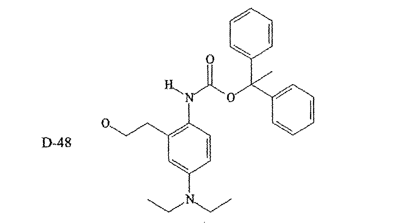


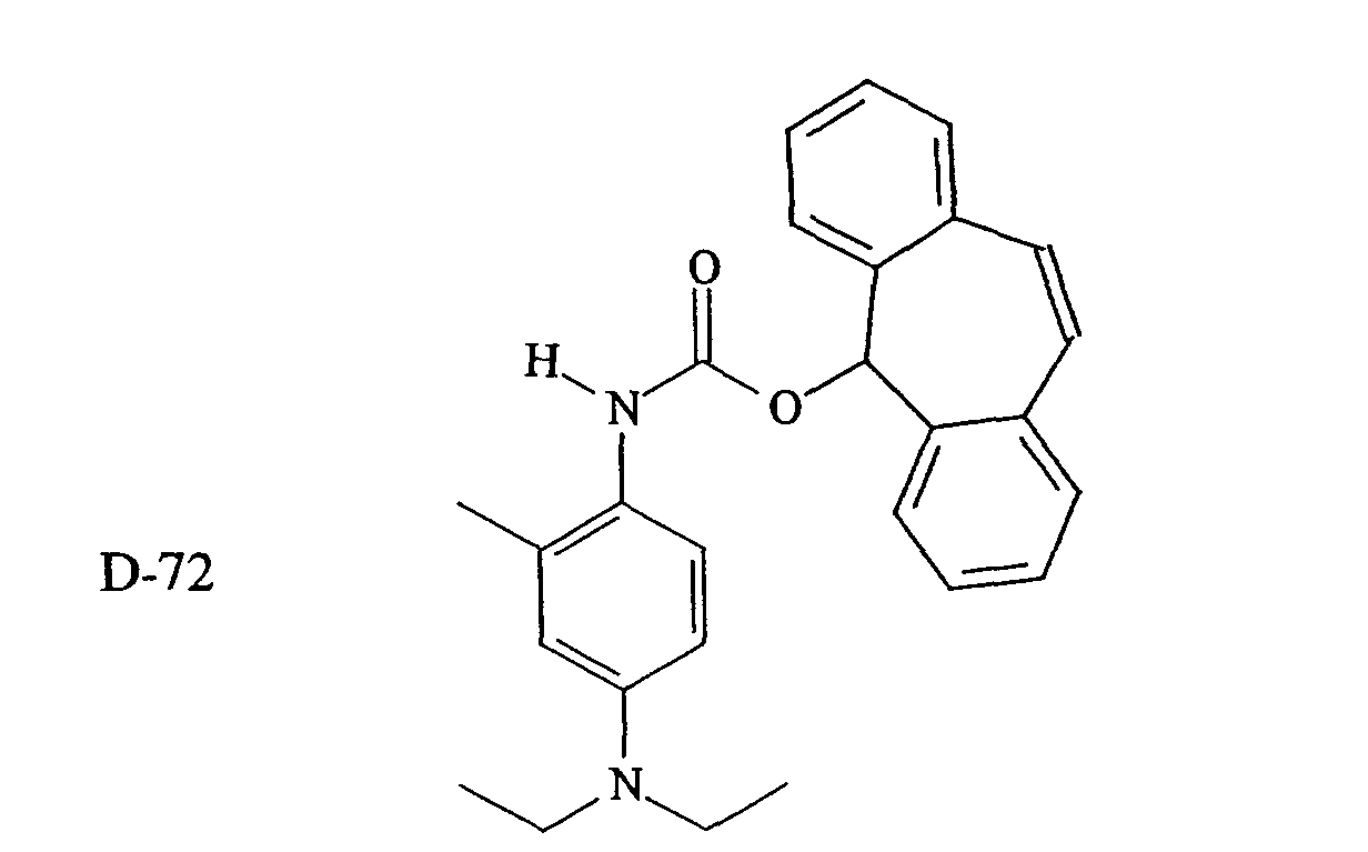


- In another embodiment of the invention, both Blocked Developers A and B fall within the scope of Structure II or IIB above.
- In another embodiment of the present invention, a Blocked Developer A or Blocked Developer B has a blocking group comprising a disubstituted nitrogen (NIT), for example a substituted or unsubstituted benzimidazolyl, benzothiazolyl, benzoxazolyl, benzothiophenyl,benzofuryl, furyl, imidazolyl, indazolyl, indolyl, isoquinolyl, isothiazolyl, isoxazolyl, oxazolyl, picolinyl, purinyl, , pyranyl, pyrazinyl, pyrazolyl, pyridyl, pyrimidinyl, pyrrolyl, quinaldinyl, quinazolinyl, quinolyl, quinoxalinyl, tetrazolyl, thiadiazolyl, thiatriazolyl, thiazolyl, thiophenyl, triazolyl, diphenylamino and carbazolyl group. Particularly preferred are: 1-imidazolyl, 1-benzimidazolyl, 1-pyrrolyl, 1-indolyl, 1-carbazolyl, 1-pyrazolyl, 1-indazolyl, N,N-diarylamino, and 1-tetrahydrocarbazolyl . The heterocyclic group may be further substituted. Preferred substituents are alkyl and alkoxy groups containing 1 to 6 carbon atoms.
- In one referred embodiment of the invention, the photographic element comprising an imaging layer having in association therewith a blocked developer of Structure IV:wherein

- PUG is a photographically useful group;
-
LINK 1 andLINK 2 are first and second linking groups adjacent, respectively the timing group and the blocking group; - TIME is a timing group;
- T represents t independently selected substituted or unsubstituted alkyl (preferably containing 1 to 6 carbon atoms) or aryl groups (preferably phenyl or naphthyl), t is 0, 1, or 2 and if t is 2, the T groups can form a ring;
- NIT is a disubstituted nitrogen group which optionally can form a ring system with a T group;
- l is 0 or 1;
- m is 0, 1, or 2; and
- n is 0 or 1.
-
- It will be observed that the Blocked Developer of Structure V is according to Structure I with the B group having the following Structure IVA:wherein

- T represents t independently selected substituted or unsubstituted alkyl or aryl groups, t is 0, 1, or 2 and if t is 2, the T groups can form a ring; and
- NIT is a disubstituted nitrogen group which optionally can form a ring.
-
- Particularly preferred photographically useful compounds of the class of blocked developing agents according to Structure IV have the following Structure IVB:wherein:

- W is OH or NR2R3, and R2 and R3 are independently hydrogen or a substituted or unsubstituted alkyl group or R2 and R3 are connected to form a ring;
- R5, R6, R7, and R8 are independently hydrogen, halogen, hydroxy, amino, alkoxy, carbonamido, sulfonamido, alkylsulfonamido or alky], or R5 can connect with R3 or R6 and/or R8 can connect to R2 or R7 to form a ring;
- T is hydrogen, alkyl, aryl, heteroaromatic or alkoxy groups, -NO2,-CN, an electron withdrawing group substituted by R13 (-SO2R13, -OSO2R13,-N(SO2)R13, -CO2R13, -CCl2R13, -N(C=O)R13, etc; or when T is a divalent group it can combine with R10 or R11 to form a ring. Preferably, T is an electron withdrawing group, including akyl groups or aryl groups substituted with one to seven electron withdrawing groups.
-
- R10 and R11 are independently alkyl, aryl, substituted aryl or heteroaromatic substituents which can be connected to form a ring system with the nitrogen atom that is a heteroaromatic or saturated or unsaturated heterocyclic ring and which may optionally contain additional heteroatoms.
- In another embodiment of the present invention, both blocked developers have Structure III or IIIB above. In yet another embodiment of the invention, only one of the blocked developer have Structure III and another blocked developer has Structure IV or IVB.
- When reference in this application is made to a particular moiety, or group, this means that the moiety may itself be unsubstituted or substituted with one or more substituents (up to the maximum possible number). For example, "alkyl" or "alkyl group" refers to a substituted or unsubstituted alkyl, while "aryl group" refers to a substituted or unsubstituted benzene (with up to five substituents) or higher aromatic systems, "heteroaromatic group" refers to a substituted or unsubstituted heteroaromatic (with up to five substituents), and heterocyclic group refers to a substituted or unsubstituted heterocyclic (with up to five substitutuents). Generally, unless otherwise specifically stated, substituent groups usable on molecules herein include any groups, whether substituted or unsubstituted, which do not destroy properties necessary for the photographic utility. Examples of substituents on any of the mentioned groups can include known substituents, such as: halogen, for example, chloro, fluoro, bromo, iodo; alkoxy, particularly those "lower alkyl" (that is, with 1 to 6 carbon atoms), for example, methoxy, ethoxy; substituted or unsubstituted alkyl, particularly lower alkyl (for example, methyl, trifluoromethyl); thioalkyl (for example, methylthio or ethylthio), particularly either of those with 1 to 6 carbon atoms; substituted and unsubstituted aryl, particularly those having from 6 to 20 carbon atoms (for example, phenyl); and substituted or unsubstituted heteroaryl, particularly those having a 5 or 6-membered ring containing 1 to 3 heteroatoms selected from N, O, or S (for example, pyridyl, thienyl, furyl, pyrrolyl); acid or acid salt groups such as any of those described below; and others known in the art. Alkyl substituents may specifically include "lower alkyl" (that is, having 1-6 carbon atoms), for example, methyl, ethyl, and the like. Further, with regard to any alkyl group or alkylene group or , it will be understood that these can be branched, unbranched or cyclic.
- The following are representative examples of Blocked Developer A Compounds of Structure IIIB:


- The mixture of blocked developer is preferably incorporated in one or more of the imaging layers of the imaging element. Preferably, the same mixture is used in all the imaging layers, in the same or different proportions. Alternatively, a mixture may only be present in one or some, but not all, of the imaging layers, different mixtures of blocked developers may be used in different imaging layers.
- The amount of each blocked developer used is preferably 0.01 to 5g/m2, more preferably 0.1 to 2g/m2 and most preferably 0.3 to 2g/m2 in each layer to which it is added. These may be color forming or non-color forming layers of the element. The blocked developer can be contained in a separate element that is contacted to the photographic element during processing.
- As indicated above, the onset temperature of Developing Agent A is less than the onset temperature of Developing Agent B, the onset temperature of Developing Agent A is in the range of 110 to 160°C, preferably 110 to 150°C and the onset temperature of Developing Agent B is 130 to 170°C and the difference in the onset temperatures of the two developing agents are 5 to 50°C, preferably 8 to 40°C, more preferably 10 to 30°C. In one embodiment of the invention, the at least two developing agents comprise at least two developing agents of Structure II, preferably Structure IIB. In another embodiment of the invention, the at least two developing agents comprise at least one developing agent of Structure II, preferably Structure IIB and at least one developing agent of Structure III or Structure V.
- After image-wise exposure of the imaging element, the mixture of blocked developers is activated during processing of the imaging element by the presence of acid or base in the processing solution, by heating the imaging element during processing of the imaging element, and/or by placing the imaging element in contact with a separate element, such as a laminate sheet, during processing. The laminate sheet optionally contains additional processing chemicals such as those disclosed in Sections XIX and XX of Research Disclosure, September 1996, Number 389, Item 38957 (hereafter referred to as ("Research Disclosure I"). All sections referred to herein are sections of Research Disclosure I, unless otherwise indicated. Such chemicals include, for example, sulfites, hydroxyl amine, hydroxamic acids and the like, antifoggants, such as alkali metal halides, nitrogen containing heterocyclic compounds, and the like, sequestering agents such as an organic acids, and other additives such as buffering agents, sulfonated polystyrene, stain reducing agents, biocides, desilvering agents, stabilizers and the like.
- This example illustrates the preparation of a Blocked Developer B (referred to as compound D-3) that can be used in the present invention, which blocked developer is represented by the following structure:Compound D-105 is prepared according to the following reaction scheme, starting with compound a.


- To a mixture of a (16.72g, 100 mmol), THF (120 mL) were added 37% aqueous solution of formalin (13 mL) and two drops of 50% NaOH. The reaction mixture was stirred at room temperature for 8 hours and poured into water (650 mL). The solid material was isolated by filtration to give 18.11 g (92%) of the b .
- To a mixture of b (9.87g, 50 mmol), methylene chloride (40 mL), and two drops of dibutyltin diacetate was added c (10.81g, 52 mmol). After being stirred at room temperature for 14 hours, the reaction mixture was concentrated under reduced pressure and diluted with the mixture of ligroin and ethyl acetate (4:1). The solid material was isolated by filtration to give 17.84 g (89%) of D-105, 1H NMR (300 MHz, CDCl3): 1.11 (t, J=7.3 Hz, 6H), 2.10 (s, 3H), 3.27 (q, J=7.3Hz, 4H), 6.12 (s, 1H), 6.28-6.59 (m, 4H), 7.15-7.35 (m, 3H), 7.39-7.56 (m, 2H), 7.42-7.55 (t, 2H), 7.65-7.74 (d, 2H), 8.06 (d, 2H).
- This example illustrates the synthesis of a representative Blocked Developer A useful in the invention. This compound is referred to above as blocked developing agent D-10, and is prepared according to the following reaction scheme:

- Propylene oxide ( 1 , 7.2 mL, 105 mmol), sodium methanesulfinate ( 9.19 g, 90 mmol), and monobasic sodium phosphate monohydrate (16.56 g) were heated in 100 mL of water at 90°C for 18 h. The solution was cooled and extracted with 4x100 mL of ethyl acetate. The extracts were dried over sodium sulfate and concentrated to a solid. The yield of 2 was 6.42 g (46 mmol, 52 %).
- A solution of 2 (3.32 g, 24 mmol), compound 3 (4.08 g, 20 mmol), and dibutyltin diacetate (0.05 mL) in 60 mL of 1,2-dichloroethane was stirred at room temperature for 7 days. The crude reaction mixture was purified by column chromatography on silica gel. The yield of D-10 was 6.15 g (18 mmol, 90 %), m.p. 80-82°C, ESMS: ES+ m/z 343 (M+1, 100 %).
- A representative synthesis blocked developers of Structure III of the invention is described below.

- A solution of 1 (2.04 g, 10 mmol), 2a (1.83 g, 12 mmol) and pyridine (0.1 mL) in acetonitrile (25 mL) was refluxed for 18 h. The mixture was cooled , filtered and concentrated in vacuo. The crude product was purified by column chromatography, giving 1.89 g (5.3 mmol, 53 %) of D-56, m.p. 90-92°C, APMS: AP+ m/z 357 (M+1, 75%). Preparation of D-55.
- Prepared as described for D-56 from 1 and 2b. The yield: 62 %, m.p. 90-91°C, ESMS: ES+ m/z 373 (M+1, 100 %).
- This example illustrates the synthesis of another representative locked developer useful in the invention. This compound is referred to above as developing agent D-12, and is prepared according to the following reaction scheme:

Compounds - This Example illustrates the performance of a compound according to the present invention in a photographic element. The processing conditions are as described below with respect to each sample. Unless otherwise stated, the silver halide was removed after development by immersion in Kodak Flexicolor Fix solution. In general, an increase of approximately 0.2 in the measured density would be obtained by omission of this step. The following components are used in the samples, including is a list of all of the chemical structures.
- The inventive coating examples were prepared on a 7 mil thick poly(ethylene terephthalate) support and comprised an emulsion containing layer (contents shown below) with an overcoat layer of gelatin (0.22 g/m2) and 1,1'-(methylenebis(sulfonyl))bis-ethene hardener (at 2% of the total gelatin concentration). Both layers contained spreading aids to facilitate coating.
Component Laydown Silver (from emulsion E-1) 0.54 g/m2 Silver (from emulsion E-2) 0.22 g/m2 Silver (from emulsion E-3) 0.16 g/m2 Silver (from emulsion E-4) 0.11 g/m2 Silver (from silver salt SS-1) 0.32 g/m2 Silver (from silver salt SS-2) 0.32 g/m2 Coupler M-1 (from coupler dispersion Disp-1) 0.54 g/m2 Developer 2.69 mMole/m2 Salicylanilide 0.86 g/m2 Lime processed gelatin 4.3 g/m2 - A stirred reaction vessel was charged with 431 g of lime processed gelatin and 6569 g of distilled water. A solution containing 214 g of benzotriazole, 2150 g of distilled water, and 790 g of 2.5 molar sodium hydroxide was prepared (Solution B). The mixture in the reaction vessel was adjusted to a pAg of 7.25 and a pH of 8.00 by additions of Solution B, nitric acid, and sodium hydroxide as needed.
- A 4 L solution of 0.54 molar silver nitrate was added to the kettle at 250 cc/minute, and the pAg was maintained at 7.25 by a simultaneous addition of solution B. This process was continued until the silver nitrate solution was exhausted, at which point the mixture was concentrated by ultrafiltration. The resulting silver salt dispersion contained fine particles of silver benzotriazole.
- A stirred reaction vessel was charged with 431 g of lime processed gelatin and 6569 g of distilled water. A solution containing 320 g of 1-phenyl-5-mercaptotetrazole , 2044 g of distilled water, and 790 g of 2.5 molar sodium hydroxide was prepared (Solution B). The mixture in the reaction vessel was adjusted to a pAg of 7.25 and a pH of 8.00 by additions of Solution B, nitric acid, and sodium hydroxide as needed. A 4 1 solution of 0.54 molar silver nitrate was added to the kettle at 250 cc/minute, and the pAg was maintained at 7.25 by a simultaneous addition of solution B. This process was continued until the silver nitrate solution was exhausted, at which point the mixture was concentrated by ultrafiltration. The resulting silver salt dispersion contained fine particles of the silver salt of 1-phenyl-5-mercaptotetrazole.
- Silver halide emulsions were prepared by conventional means to have the following morphologies and compositions. . The emulsions were spectrally sensitized to green light by addition of sensitizing dyes and then chemically sensitized for optimum performance.
- E-1:pfm-3470 a tabular emulsion with composition of 96% silver bromide and 4% silver iodide and an equivalent circular diameter of 1.2 microns and a thickness of 0.12 microns
- E-2: UB6905-SM3 a tabular emulsion with composition of 98% silver bromide and 2% silver iodide and an equivalent circular diameter of 0.45 microns and a thickness of 0.006 microns.
- E-3: mm742-sml a tabular emulsion with composition of 98% silver bromide and 2% silver iodide and an equivalent circular diameter of 0.79 microns and a thickness of 0.009 microns.
- E-4: pdz208-ml a cubic emulsion with composition of 97% silver bromide and 3% silver iodide and size of 0.16 microns.
- An oil based coupler dispersion was prepared containing coupler M-1 [241ANY], tricresyl phosphate and 2-butoxy-N,N-dibutyl-5-(1,1,3,3-tetramethylbutyl)-benzenamine, at a weight ratio of 1:0.8:0.2.

- The high To incorporated developer D-12 had the following structure:

- This material was ball-milled in an aqueous mixture, for 4 days using Zirconia beads in the following formula. For 1 g of Incorporated developer, sodium tri-isopropylnaphthalene sulfonate (0.1 g), water ( to 10 g), and beads (25 ml), were used. In some cases, after milling, the slurry was diluted with warmed (40°C) gelatin solution (12.5%, 10 g) before the beads were removed by filtration. The filtrate (with or without gelatin addition) was stored in a refrigerator prior to use.
- This material was incorporated in the same way as for Dev-1. The structure of the low To incorporated developer is D-104.
- The resulting coatings were exposed through a step wedge to a 3.04 log lux light source at 3000K filtered by Daylight 5A, 0.6 Inconel and Wratten 9 filters. The exposure time was 0.1 seconds. After exposure, the coating was thermally processed by contact with a heated platen for 20 seconds. A number of strips were processed at a variety of platen temperatures in order to check the generality of the effects that were seen. . Density measurements were made at each step and from these data, two parameters were obtained:
- A. Onset Temperature, To: Corresponds the temperature required to produce a maximum density (Dmax) of 0.5. Lower temperatures indicate more active developers which are desirable.
- B. Peak Discrimination, DP: For the optimum platen temperature, the peak
discrimination corresponds to the value:
-
- These data show that by incorporating Dev-2 into coatings containing Dev-1, the onset temperature can be greatly reduced (by 19 °C ) while maintaining a good peak discrimination.
- This used a similar coating structure and similar components to those in Example 6 with the following changes:
The emulsions were spectrally sensitized to blue light by addition of sensitizing dyes and then chemically sensitized for optimum performance. - E-5 replaced E-1:UB7019 and was a tabular emulsion with composition of 98% silver bromide and 2% silver iodide and an equivalent circular diameter of 1.2 microns and a thickness of 0.12 microns
- E-6 replaced E-2: UB6905- and was a tabular emulsion with composition of 98% silver bromide and 2% silver iodide and an equivalent circular diameter of 0.45 microns and a thickness of 0.006 microns.
- E-7 replaced E-3: mm742 and was a tabular emulsion with composition of 98% silver bromide and 2% silver iodide and an equivalent circular diameter of 0.79 microns and a thickness of 0.009 microns.
- E-8 replaced E-4: pdz208 and was a cubic emulsion with composition of 97% silver bromide and 3% silver iodide and size of 0.16 microns. Salicylanilide was coated at 0.65g/m2 Coupler Y-1 replaced M-1. An oil based coupler dispersion was prepared containing coupler Y-1, 1,2-benzenedicarboxylic acid, dibutyl ester, at a weight ratio of 1:0.5.
-
- The resulting coatings were exposed through a step wedge to a 3.04 log lux light source at 3000K filtered by Daylight 5A, and Wratten 2B filters. The exposure time was 0.1 seconds. After exposure, the coating was thermally processed by contact with a heated platen for 20 seconds. A number of strips were processed at a variety of platen temperatures in order to check the generality of the effects that were seen. The coatings described above performed as shown in the Table 6-1 below.
Coating Developer To (°C) DP I-4 Dev-1 141 7.7 I-5 90% Dev-1 + 10% Dev-2 137 5.1 I-6 80% Dev-1 + 20% Dev-2 135 4.1 I-7 50% Dev-1 + 50% Dev-2 131 3.7 I-8 Dev-2 122 2.5 - The reduction in onset temperature with increasing level of Dev-2 can be seen. In particular, a decrease in 10°C is obtained by using 50% of Dev-2.
- The following components were used in the creation of the sample photographic element of this example:
- A stirred reaction vessel was charged with 431 g of lime processed gelatin and 6569 g of distilled water. A solution containing 214 g of benzotriazole, 2150 g of distilled water, and 790 g of 2.5 molar sodium hydroxide was prepared (Solution B). The mixture in the reaction vessel was adjusted to a pAg of 7.25 and a pH of 8.00 by additions of Solution B, nitric acid, and sodium hydroxide as needed. A 4 1 solution of 0.54 molar silver nitrate was added to the kettle at 250 cc/minute, and the pAg was maintained at 7.25 by a simultaneous addition of solution B. This process was continued until the silver nitrate solution was exhausted, at which point the mixture was concentrated by ultrafiltration. The resulting silver salt dispersion contained fine particles of silver benzotriazole.
- A silver halide tabular emulsion was precipitated by means known in the art. The emulsion contained 98% silver bromide and 2% silver iodide, and had dimensions of 1.2 microns in effective circular diameter by 0.12 microns in thickness. The emulsion was spectrally sensitized to green light by addition of dyes SM-1 and SM-2, and then was chemically sensitized to an optimum position as is known in the art.
- A coupler dispersion was prepared by conventional means containing coupler M-1 without any additional permanent solvents.


- All coatings for this example contain a single light sensitive layer and were prepared according to the format listed in Table 7-1, with variations consisting of changing the incorporated developer. The total developer laydown was kept constant in all coatings at 2.21 mmols/m2, while the ratio of developer types was varied. All coatings were prepared on a 7 mil thick poly(ethylene terephthalate) support.
Component Laydown Silver (from emulsion E-1) 0.86 g/m2 Silver (from silver salt SS-1) 0.32 g/m2 Silver (from silver salt SS-2) 0.32 g/m2 Coupler M-1 (from coupler dispersion CDM-1) 0.54 g/m2 Salicylanilide 0.86 g/m2 Lime processed gelatin 4.31 g/m2 - The developers listed in table 7-2 below were tested in combination. Developers were ball-milled in an aqueous slurry for 3 days using Zirconia beads in the following formula. For each gram of incorporated developer, 0.2 g of sodium tri-isopropylnaphthalene sulfonate, 10 g of water, and 25 ml of beads were added. Following milling, the zirconia beads were removed by filtration. The slurry was refrigerated prior to use.

- The resulting coatings were exposed through a step wedge to a 3.04 log lux light source at 3000K filtered by Daylight 5A and Wratten 2B filters. The exposure time was 1 second. After exposure, the coating was thermally processed by contact with a heated platen for 20 seconds. A number of strips were processed at a variety of platen temperatures in order to yield an optimum strip process condition. From this data, two parameters were obtained:
- Corresponds the temperature required to produce a maximum density (Dmax) of 0.5. Lower temperatures indicate more active developers which are desirable.
- For the optimum platen temperature, the peak discrimination corresponds to the value:
- Higher values of DP indicate developers producing enhanced signal to noise, which are desirable.
- Table 7-3 shows the results for the coatings used in this example. Items listed are the percentages of each of developers D-1 and D-2, the onset temperature To, and the relative discrimination, Dp.
Coating % D-1 % D-2 To (°C) DP 1-1 100 0 136.0 5.21 1-2 67 33 137.5 7.66 1-3 33 67 141.0 7.82 1-4 0 100 151.7 5.72 - It can be seen by examination of Table 8-3 that the combination of blocked developers D-1 and D-2 yields onset temperatures lower than that of developer D-2 alone while providing superior image discrimination to either blocked developer alone.
- To further illustrate the advantage of the invention, a photothermographic element was constructed on polyethyleneterephthalate support with the following components:
Component Laydown Silver (from emulsion E-2) 0.86 g/m2 Silver (from silver salt SS-1) 0.64 g/m2 5-phenyl-1-mercaptotetrazole 0.32 g/m2 Coupler M-2 0.54 g/m2 Lime processed gelatin 4.31 g/m2 - Emulsion E-2 is a silver halide tabular emulsion with a composition of 98.7% silver bromide and 1.3% silver iodide, prepared by conventional means. The resulting emulsion had an equivalent circular diameter of 0.6 microns and a thickness of 0.09 microns. This emulsion was spectrally sensitized to yellow light by addition of dye Y-2 and then chemically sensitized for optimum performance. The structure of coupler M-2 is given below. It was incorporated into the photothermographic coatings as an oil-in-water dispersion using tricresyl phosphate as a coupler solvent in the manner well known in the art.In addition to the above components, each coating also contained developer D-28 or D94BR, or a mixture of the two developers as given in Table 8-3.


Coating Amount of Developer D-12 Amount of Developer D-55 9-1 0.75 g/m2 0 g/m2 9-2 0 g/m2 0.83 g/m2 9-3 0.60 g/m2 0.17 g/m2 9-4 0.45 g/m2 0.33 g/m2 9-5 0.30 g/m2 0.50 g/m2 - The resulting coatings were exposed through a step wedge to a 3.04 log lux light source at 3000K filtered by Daylight 5A and Wratten 2B filters. The exposure time was I second. Following exposure, the coatings were thermally processed by contact with a heated platen for 20 seconds. A number of strips were processed at a variety of platen temperatures in order to yield an optimum strip process condition. The peak discrimination at a process temperature of 150 degrees C is given in Table 9-2. Also presented in Table 9-2 is the temperature sensitivity exhibited by each photothermographic coating. The temperature sensitivity is defined as the slope of the peak discrimination versus process temperature. A slope near zero is desired, as it indicates little change in peak discrimination as the process temperature is varied.
Coating Developer To Dp (150 °C) Temperature Sensitivity 9-1 D-12 (Comparison) 135 2.86 0.21 9-2 D-55 (Comparison) 150 1.12 0.17 9-3 Mixture 1 (Inv.) 138 3.73 0.16 9-4 Mixture 2 (Inv.) 140 4.12 0.13 9-5 Mixture 3 (Inv.) 142 3.77 0.01 - It is clear from these examples that photothermographic elements that contain a mixture of two developers exhibit improved relative discrimination compared to either developer when used alone. In addition, the inventive combinations effectively lower the onset temperature for the blocked developer with the higher To. Furthermore, the photothermographic elements that use a mixture of developers exhibit lower sensitivity to temperature, rendering them more robust to temperature variations in the processing equipment.
- This example demonstrates the advantageous use of a combination of blocked developer in a multilayer film element intended for multiple color capture and reproduction. The following components were used in the creation of this example.
- A stirred reaction vessel was charged with 431 g of lime processed gelatin and 6569 g of distilled water. A solution containing 320 g of 1-phenyl-5-mercaptotetrazole , 2044 g of distilled water, and 790 g of 2.5 molar sodium hydroxide was prepared (Solution B). The mixture in the reaction vessel was adjusted to a pAg of 7.25 and a pH of 8.00 by additions of Solution B, nitric acid, and sodium hydroxide as needed. A 41 solution of 0.54 molar silver nitrate was added to the kettle at 250 cc/minute, and the pAg was maintained at 7.25 by a simultaneous addition of solution B. This process was continued until the silver nitrate solution was exhausted, at which point the mixture was concentrated by ultrafiltration. The resulting silver salt dispersion contained fine particles of the silver salt of 1-phenyl-5-mercaptotetrazole.
Emulsion Spectral sensitivity Iodide content (%) Diameter (µm) Thickne ss (µm) Dyes EY-1 yellow 4 1.97 0.13 SY-1 EY-2 yellow 2 1.23 0.125 SY-1 EY-3 yellow 2 0.42 0.061 SY-1 EY-4 yellow 1.95 0.653 0.092 SY-1 EY-5 yellow 3.4 0.16 (cube) SY-1 EY-6 yellow 3.4 0.10 (cube) SY-1 EY-7 yellow 3.4 0.05 (cube) SY-1 EM-1 magenta 4 1.97 0.13 SM-1+SM-2 EM-2 magenta 4 1.25 0.106 SM-1+SM-2 EM-3 magenta 2 0.42 0.061 SM-1+SM-2 EM-4 magenta 1.95 0.653 0.092 SM-1+SM-2 EM-5 magenta 3.4 0.16 (cube) SM-1+SM-2 EM-6 magenta 3.4 0.10 (cube) SM-1+SM-2 EM-7 magenta 3.4 0.05 (cube) SM-1+SM-2 EC-1 cyan 4 1.97 0.13 SC-1 + SC-2 EC-2 cyan 4 1.25 0.106 SC-1 + SC-2 EC-3 cyan 2 0.42 0.061 SC-1 + SC-2 EC-4 cyan 1.95 0.653 0.092 SC-1 +SC-2 EC-5 cyan 3.4 0.16 (cube) SC-1 +SC-2 EC-6 cyan 3.4 0.10 (cube) SC-1 +SC-2 EC-7 cyan 3.4 0.05 (cube) SC-1 + SC-2 - A coupler dispersion was prepared by conventional means containing coupler M-1 without any additional permanent solvents.
- An oil based coupler dispersion was prepared by conventional means containing coupler C-1 and dibutyl phthalate at a weight ratio of 1:2.
- An oil based coupler dispersion was prepared by conventional means containing coupler Y-1 and dibutyl phthalate at a weight ratio of 1:0.5.


- A basic multilayer imaging element as described in table 2-2 was created. Variations in coating examples consisted of changing the respective amounts of developing agents D-1 and D-2 while maintain the overall molar laydowns of developer as listed in Table 10-2 below. The composition of the test coatings is shown in Table 10-3.
Overcoat 1.1 g/m2 Gelatin 0.32 g/m2 Hardener-1 Fast Yellow 0.48 g/m2 AgBrI from emulsion EY-1
0.15 g/m2 silver benzotriazole from SS-1
0.15 g/m2 silver-1-phenyl-5-mercaptotetrazole from SS-2
0.21 g/m2 coupler Y-1 from dispersion CDY-1
1.61 mmol/m2 Total Developer
0.52 g/m2 Salicylanilide
1.56 g/m2 GelatinSlow Yellow 0.22 g/m2 AgBrI from emulsion EY-2
0.11 g/m2 AgBrI from emulsion EY-3
0.092 g/m2 AgBrI from emulsion EY-4
0.065 g/m2 AgBrI from emulsion EY-5
0.065 g/m2 AgBrI from emulsion EY-6
0.43 g/m2 AgBrI from emulsion EY-7
0.24 g/m2 silver benzotriazole from SS-1
0.24 g/m2 silver-1-phenyl-5-mercaptotetrazole from SS-2
0.39 g/m2 coupler Y-1 from dispersion CDY-1
1.80 mmol/m2 Total Developer
0.58 g/m2 Salicylanilide
2.75 g/m2 GelatinYellow Filter 0.13 g/m2 SY-2
1.08 g/m2 GelatinFast Magenta 0.48 g/m2 AgBrI from emulsion EM-1
0.15 g/m2 silver benzotriazole from SS-1
0.15 g/m2 silver-1-phenyl-5-mercaptotetrazole from SS-2
0.21 g/m2 coupler M-1 from dispersion CDM-1
0.90 mmol/m2 Total Developer
0.29 g/m2 Salicylanilide
1.56 g/m2 GelatinSlow Magenta 0.22 g/m2 AgBrI from emulsion EM-2
0.11 g/m2 AgBrI from emulsion EM-3
0.11 g/m2 AgBrI from emulsion EM-4
0.11 g/m2 AgBrI from emulsion EM-5
0.065 g/m2 AgBrI from emulsion EM-6
0.065 g/m2 AgBrI from emulsion EM-7
0.24 g/m2 silver benzotriazole from SS-1
0.24 g/m2 silver-1-phenyl-5-mercaptotetrazole from SS-2
0.39 g/m2 coupler M-1 from dispersion CDM-1
0.96 mmol/m2 Total Developer
0.31 g/m2 Salicylanilide
2.75 g/m2 GelatinInterlayer 1.07 g/m2 Gelatin Fast Cyan 0.48 g/m2 AgBrI from emulsion EC-1
0.15 g/m2 silver benzotriazole from SS-1
0.15 g/m2 silver-1-phenyl-5-mercaptotetrazole from SS-2
0.21 g/m2 coupler C-1 from dispersion CDC-1
1.61 mmol/m2 Total Developer
0.52 g/m2 Salicylanilide
1.56 g/m2 GelatinSlow Cyan 0.22 g/m2 AgBrI from emulsion EC-2
0.11 g/m2 AgBrI from emulsion EC-3
0.11 g/m2 AgBrI from emulsion EC-4
0.11 g/m2 AgBrI from emulsion EC-5
0.065 g/m2 AgBrI from emulsion EC-6
0.065 g/m2 AgBrI from emulsion EC-7
0.24 g/m2 silver benzotriazole from SS-1
0.24 g/m2 silver-1-phenyl-5-mercaptotetrazole from SS-2
0.39 g/m2 coupler C-1 from dispersion CDC-1
1.80 mmol/m2 Total Developer
0.58 g/m2 Salicylanilide
2.75 g/m2 GelatinAntihalation Layer 0.108 g/m2 AD-1
1.6 g/m2 GelatinSupport Polyethylene terephthalate support (4 mil thickness) Developer Fractions Coating % Dev-1 %Dev-2 2-1 100 0 2-2 50 50 2-3 0 100 - The resulting coatings were exposed through a step wedge to a 2.1 log lux light source at 5500K and Wratten 2B filter. The exposure time was 0.1 seconds. The step wedge contained 21 steps each separated by 0.2 log(E), to yield on overall exposure range of 4.0 log(E).
- After exposure, the coating was thermally processed by contact with a heated platen for 20 seconds at 154°C. Cyan, magenta, and yellow densities corresponding to each step were read using status M color profiles. The average gamma of the coatings were calculated for each record by regressing a linear fit to the densities formed from steps that exhibited densities above Dmin. Table 10-4 shows the measured gammas and Dmins of three coatings two of which have pure developers and the other having a combination of 50% of each of Dev-1 and Dev-2. Considering that a minimum gamma of approximately 0.3 is required for faithful image reproduction from a scanning operation, it can be seen that the inventive combination (example 2-2) containing a mixture of developers shows acceptable gamma while maintaining a low Dmin position. The comparative coating with Dev-1 alone (example C2-1) shows acceptable gamma but excessive Dmin while the comparative coating with Dev-2 alone (example C2-3) shows acceptable Dmin but insufficient gamma.
Gamma Dmin Coating Cyan Magenta Yellow Cyan Magenta Yellow 2-1 (Comp.) 0.51 0.84 0.65 0.371 0.504 0.861 2-2 (Inv.) 0.38 0.67 0.52 0.160 0.322 0.675 2-3 (Comp.) 0.15 0.23 0.16 0.141 0.308 0.746
The coatings shown above performed as shown in the Table 5-2 below.
| Coating | Developer | To (°C) | DP |
| I-1 | Dev-1 | 135 | 9.6 |
| I-2 | 80% Dev-1 + 20% Dev-2 | 116 | 5.0 |
| I-3 | Dev-2 | 110 | 2.0 |

Claims (10)
- A photothermographic color element comprising at least three light-sensitive units that have their individual sensitivities in different wavelength regions comprising a silver halide imaging layer having associated therewith a first imaging layer or color unit, referred to as Layer 1 or Color Unit 1, having a mixture of at least two blocked developing agents comprising Blocked Developer A and Blocked Developer B and a second imaging layer or color unit, referred to as Layer 2 or Color Unit 2, having at least one blocked developer C, wherein blocked developers A, B, and C are independently represented by the following Structure:andDEV is a silver halide color developing agent;LINK 1 and LINK 2 are linking groups;TIME is a timing group;1 is 0 or 1;m is 0, 1, or 2;n is 0 or 1;1 + n is 1 or 2;B is a blocking group or B is:wherein the onset temperature of Developer B is less than the onset temperature of Developer A, the onset temperature of Developer B is in the range of 110 to 160C and the onset temperature of Developer A is 130 to 170C and the difference in the onset temperatures of the two developing agents are 5 to 50 C, preferably 8 to 40, more preferably 10 to 30C, andwherein the Gamma Ratio at the process temperature of the Gamma in Layer 1 to the Gamma in Layer 2 is between 0.8 and 1.2 and wherein this Gamma Ratio is at least 10% closer to 1.0 than if only one of Blocked Developers A, B, and C are independently used in each of Layer 1 and Layer 2; and/orwherein the Dmin Ratio at the process temperature of the Dmin in Layer 1 to the Dmin in Layer 2 is between 0.8 and 1.2, and wherein this Dmin ratio is at least 10% closer to 1.0 than if only one of Blocked Developers A, B, and C are independently used in each of Layer 1 and Layer 2.; and/orwherein the Latitude Ratio at the process temperature of the Latitude in Layer 1 to the Latitude in Layer 2 is between 0.8 and 1.2 and wherein this Latitude Ratio is at least 10% closer to 1.0 than if only one of Blocked Developers A, B, and C are independently used in each of Layer 1 and Layer 2.
- A photothermographic color element according to claim 1 wherein Layer 1 and 2 are in different color units.
- A photothermographic color element according to claim 1 wherein a mixture of at least two blocked developers, Blocked Developer C and Blocked Developer D is present in Layer 2.
- The photographic element of claim 1 wherein the difference in the onset temperatures of the two developing agents in the mixture are 5 to 50°C.
- A photothermographic color element according to claim 1, where LINK 1 and LINK 2 have the following structure:wherein
 with the proviso that when X is carbon, both p and r are 1, when X is sulfur, Y is oxygen, p is 2 and r is 0;X represents carbon or sulfur;Y represents oxygen, sulfur or N-R1, where R1 is substituted or unsubstituted alkyl or substituted or unsubstituted aryl;p is 1 or 2;Z represents carbon, oxygen or sulfur,r is 0 or 1;# denotes the bond to PUG (for LINK I) or TIME (for LINK 2):$ denotes the bond to TIME (for LINK I) or T(t) substituted carbon (for LINK 2).
 - A photothermographic color element according to claim 10, where LINK 1 and LINK 2 are the following:

- A photothermographic color element of claim 1 wherein B in Blocked Developer B is:wherein
 T represents t independently selected substituted or unsubstituted alkyl or aryl groups, t is 0, 1, or 2 and if t is 2, the T groups can form a ring; andNIT is a disubstituted nitrogen group which optionally can form a ring.
 - A photothermographic color element according to claim 7, wherein NIT is selected from the group consisting of: benzimidazolyl, benzothiazolyl, benzoxazolyl, benzothiophenyl, benzofuryl, furyl, imidazolyl, indazolyl, indolyl, isoquinolyl, isothiazolyl, isoxazolyl, oxazolyl, picolinyl, purinyl, , pyranyl, pyrazinyl, pyrazolyl, pyridyl, pyrimidinyl, pyrrolyl, quinaldinyl, quinazolinyl, quinolyl, quinoxalinyl, tetrazolyl, thiadiazolyl, thiatriazolyl, thiazolyl, thiophenyl, triazolyl, N,N-diarylamino, carbazolyl, and substituted derivatives thereof.
- A photothermographic color element according to claim 1, wherein the Blocked Developer A or both Blocked Developer A and B is of the following structure:wherein:
 X is a second activating group and is a divalent electron withdrawing group;DEV is a developing agent;LINK is a linking group;TIME is a timing group; n is 0, 1, or 2;t is 0, 1, or 2, and when t is not 2, the necessary number of hydrogens (2-t) are present in the structure;C* is tetrahedral (sp3 hybridized) carbon;p is 0 or 1;q is 0 or 1;w is 0 or 1;p + q = 1 and when p is 1, q and w are both 0; when q is 1, then w is 1;R12 is hydrogen, or a substituted or unsubstituted alkyl, cycloalkyl, aryl or heterocyclic group or R12 can combine with W to form a ring;T is independently selected from a substituted or unsubstituted (referring to the following T groups) alkyl group, cycloalkyl group, aryl, or heterocyclic group, an inorganic monovalent electron withdrawing group, or an inorganic divalent electron withdrawing group capped with at least one C1 to C10 organic group (either an R13 or an R13 and R14 group), preferably capped with a substituted or unsubstituted alkyl or aryl group; or T is joined with W or R12 to form a ring; or two T groups can combine to form a ring;D is a first activating group selected from substituted or unsubstituted (referring to the following D groups) heteroaromatic group or aryl group or monovalent electron withdrawing group, wherein the heteroaromatic can optionally form a ring with T or R12;W is W' or a group represented by the following structure:
 W' is independently selected from a substituted or unsubstituted (referring to the following W' groups) alkyl (preferably containing 1 to 6 carbon atoms), cycloalkyl (including bicycloalkyls, but preferably containing 4 to 6 carbon atoms), aryl (such as phenyl or naphthyl) or heterocyclic group; and wherein W' in combination with T or R12 can form a ring;R13, R14, R15, and R16 can independently be selected from substituted or unsubstituted alkyl, aryl, or heterocyclic group; andany two members of the following set: R12, T, and either D or W, that are not directly linked may be joined to form a ring, provided that creation of the ring will not interfere with the functioning of the blocking group.
 - A photothermographic color element according to claim 1, wherein the imaging element contains at least unit comprising a non-light sensitive silver salt oxidizing agent and a reducing agent.
Applications Claiming Priority (2)
| Application Number | Priority Date | Filing Date | Title |
|---|---|---|---|
| US21145300P | 2000-06-13 | 2000-06-13 | |
| US211453P | 2000-06-13 |
Publications (2)
| Publication Number | Publication Date |
|---|---|
| EP1164417A2 true EP1164417A2 (en) | 2001-12-19 |
| EP1164417A3 EP1164417A3 (en) | 2002-08-07 |
Family
ID=22786986
Family Applications (1)
| Application Number | Title | Priority Date | Filing Date |
|---|---|---|---|
| EP01202069A Withdrawn EP1164417A3 (en) | 2000-06-13 | 2001-05-31 | Color photothermographic element containing a mixture of blocked developers for balancing imaging layers |
Country Status (4)
| Country | Link |
|---|---|
| US (1) | US6472111B1 (en) |
| EP (1) | EP1164417A3 (en) |
| JP (1) | JP2002023330A (en) |
| CN (1) | CN1329280A (en) |
Citations (4)
| Publication number | Priority date | Publication date | Assignee | Title |
|---|---|---|---|---|
| US4157915A (en) * | 1977-05-02 | 1979-06-12 | Fuji Photo Film Co., Ltd. | Color photographic light-sensitive material containing development precursor |
| JPS5672442A (en) * | 1979-11-19 | 1981-06-16 | Olympus Optical Co Ltd | Color developing solution for color photosensitive material |
| EP0393523A2 (en) * | 1989-04-17 | 1990-10-24 | Fuji Photo Film Co., Ltd. | Color developing agent and image forming process |
| JPH1090854A (en) * | 1996-09-18 | 1998-04-10 | Fuji Photo Film Co Ltd | Heat-developable color photosensitive material |
Family Cites Families (2)
| Publication number | Priority date | Publication date | Assignee | Title |
|---|---|---|---|---|
| US6306551B1 (en) * | 1999-12-30 | 2001-10-23 | Eastman Kodak Company | Imaging element containing a blocked photographically useful compound |
| US6319640B1 (en) * | 2000-05-26 | 2001-11-20 | Eastman Kodak Company | Imaging element containing a blocked photographically useful compound |
-
2000
- 2000-11-20 US US09/717,742 patent/US6472111B1/en not_active Expired - Fee Related
-
2001
- 2001-05-31 EP EP01202069A patent/EP1164417A3/en not_active Withdrawn
- 2001-06-13 JP JP2001178882A patent/JP2002023330A/en active Pending
- 2001-06-13 CN CN01121291A patent/CN1329280A/en active Pending
Patent Citations (4)
| Publication number | Priority date | Publication date | Assignee | Title |
|---|---|---|---|---|
| US4157915A (en) * | 1977-05-02 | 1979-06-12 | Fuji Photo Film Co., Ltd. | Color photographic light-sensitive material containing development precursor |
| JPS5672442A (en) * | 1979-11-19 | 1981-06-16 | Olympus Optical Co Ltd | Color developing solution for color photosensitive material |
| EP0393523A2 (en) * | 1989-04-17 | 1990-10-24 | Fuji Photo Film Co., Ltd. | Color developing agent and image forming process |
| JPH1090854A (en) * | 1996-09-18 | 1998-04-10 | Fuji Photo Film Co Ltd | Heat-developable color photosensitive material |
Non-Patent Citations (2)
| Title |
|---|
| PATENT ABSTRACTS OF JAPAN vol. 005, no. 134 (P-077), 26 August 1981 (1981-08-26) & JP 56 072442 A (OLYMPUS OPTICAL CO LTD), 16 June 1981 (1981-06-16) * |
| PATENT ABSTRACTS OF JAPAN vol. 1998, no. 09, 31 July 1998 (1998-07-31) & JP 10 090854 A (FUJI PHOTO FILM CO LTD), 10 April 1998 (1998-04-10) * |
Also Published As
| Publication number | Publication date |
|---|---|
| JP2002023330A (en) | 2002-01-23 |
| EP1164417A3 (en) | 2002-08-07 |
| CN1329280A (en) | 2002-01-02 |
| US6472111B1 (en) | 2002-10-29 |
Similar Documents
| Publication | Publication Date | Title |
|---|---|---|
| US4725530A (en) | Silver halide color photographic material | |
| JP2870543B2 (en) | Color photographic recording materials containing novel colored cyan couplers | |
| US5256525A (en) | Blocked incorporated developers in a photographic element | |
| JP2753292B2 (en) | Silver halide color photographic photosensitive material | |
| WO2001050195A1 (en) | Packaged color photographic film comprising a blocked phenylenediamine developing agent and a method for processing the film | |
| JPH0440701B2 (en) | ||
| EP1158356A2 (en) | Imaging element containing a blocked photographically useful compound | |
| JPH08240892A (en) | Photographic element containing remover of oxidized developing main ingredient | |
| JPH01250953A (en) | Silver halide photographic sensitive material containing novel cyan coupler | |
| JP3247492B2 (en) | Dyes useful in photographic elements, and photographic elements | |
| US6472111B1 (en) | Color photothermographic element containing a mixture of blocked developers for balancing imaging layers | |
| EP1113316A2 (en) | Imaging element containing a blocked photographic developer | |
| EP1158359A2 (en) | Imaging element containing a blocked photographically useful compound | |
| JPH0497347A (en) | Silver halide photographic sensitive material | |
| EP1168071A2 (en) | Photothermographic element containing a mixture of blocked developers | |
| JP2004503828A (en) | Thermally developable imaging systems including protected color formers in combination with hydroxy-substituted aromatic compounds to promote imaging | |
| DE3843319C2 (en) | Color photographic recording material | |
| JPS6410061B2 (en) | ||
| US5292611A (en) | Dye image forming method | |
| EP0452883A2 (en) | Silver halide photographic materials | |
| US6551768B2 (en) | Imaging element containing a blocked photographically useful compound | |
| JP2003222970A (en) | Scannable photographic element containing high extinction high-dye-yield cyan coupler | |
| JP3675584B2 (en) | Color diffusion transfer silver halide photosensitive material and image forming method | |
| EP1321806A2 (en) | Imaging element containing a blocked photographically useful compound activated by azolesulfonyl-assisted 1,2-elimination | |
| JPS643253B2 (en) |
Legal Events
| Date | Code | Title | Description |
|---|---|---|---|
| PUAI | Public reference made under article 153(3) epc to a published international application that has entered the european phase |
Free format text: ORIGINAL CODE: 0009012 |
|
| AK | Designated contracting states |
Kind code of ref document: A2 Designated state(s): AT BE CH CY DE DK ES FI FR GB GR IE IT LI LU MC NL PT SE TR |
|
| AX | Request for extension of the european patent |
Free format text: AL;LT;LV;MK;RO;SI |
|
| PUAL | Search report despatched |
Free format text: ORIGINAL CODE: 0009013 |
|
| AK | Designated contracting states |
Kind code of ref document: A3 Designated state(s): AT BE CH CY DE DK ES FI FR GB GR IE IT LI LU MC NL PT SE TR |
|
| AX | Request for extension of the european patent |
Free format text: AL;LT;LV;MK;RO;SI |
|
| 17P | Request for examination filed |
Effective date: 20030111 |
|
| AKX | Designation fees paid |
Designated state(s): AT BE CH CY DE DK ES FI FR GB GR IE IT LI LU MC NL PT SE TR |
|
| 17Q | First examination report despatched |
Effective date: 20031022 |
|
| STAA | Information on the status of an ep patent application or granted ep patent |
Free format text: STATUS: THE APPLICATION IS DEEMED TO BE WITHDRAWN |
|
| 18D | Application deemed to be withdrawn |
Effective date: 20040302 |