EP1164366A2 - Lightpipe for infrared reception by electronic devices - Google Patents
Lightpipe for infrared reception by electronic devices Download PDFInfo
- Publication number
- EP1164366A2 EP1164366A2 EP01113055A EP01113055A EP1164366A2 EP 1164366 A2 EP1164366 A2 EP 1164366A2 EP 01113055 A EP01113055 A EP 01113055A EP 01113055 A EP01113055 A EP 01113055A EP 1164366 A2 EP1164366 A2 EP 1164366A2
- Authority
- EP
- European Patent Office
- Prior art keywords
- lightpipe
- energy
- aperture
- infrared
- entry material
- Prior art date
- Legal status (The legal status is an assumption and is not a legal conclusion. Google has not performed a legal analysis and makes no representation as to the accuracy of the status listed.)
- Withdrawn
Links
Images

Classifications
-
- G—PHYSICS
- G01—MEASURING; TESTING
- G01J—MEASUREMENT OF INTENSITY, VELOCITY, SPECTRAL CONTENT, POLARISATION, PHASE OR PULSE CHARACTERISTICS OF INFRARED, VISIBLE OR ULTRAVIOLET LIGHT; COLORIMETRY; RADIATION PYROMETRY
- G01J1/00—Photometry, e.g. photographic exposure meter
- G01J1/02—Details
- G01J1/04—Optical or mechanical part supplementary adjustable parts
-
- G—PHYSICS
- G01—MEASURING; TESTING
- G01J—MEASUREMENT OF INTENSITY, VELOCITY, SPECTRAL CONTENT, POLARISATION, PHASE OR PULSE CHARACTERISTICS OF INFRARED, VISIBLE OR ULTRAVIOLET LIGHT; COLORIMETRY; RADIATION PYROMETRY
- G01J5/00—Radiation pyrometry, e.g. infrared or optical thermometry
- G01J5/02—Constructional details
- G01J5/08—Optical arrangements
- G01J5/0818—Waveguides
-
- G—PHYSICS
- G01—MEASURING; TESTING
- G01J—MEASUREMENT OF INTENSITY, VELOCITY, SPECTRAL CONTENT, POLARISATION, PHASE OR PULSE CHARACTERISTICS OF INFRARED, VISIBLE OR ULTRAVIOLET LIGHT; COLORIMETRY; RADIATION PYROMETRY
- G01J5/00—Radiation pyrometry, e.g. infrared or optical thermometry
- G01J5/02—Constructional details
- G01J5/08—Optical arrangements
- G01J5/0875—Windows; Arrangements for fastening thereof
-
- G—PHYSICS
- G02—OPTICS
- G02B—OPTICAL ELEMENTS, SYSTEMS OR APPARATUS
- G02B6/00—Light guides; Structural details of arrangements comprising light guides and other optical elements, e.g. couplings
- G02B6/10—Light guides; Structural details of arrangements comprising light guides and other optical elements, e.g. couplings of the optical waveguide type
- G02B6/102—Light guides; Structural details of arrangements comprising light guides and other optical elements, e.g. couplings of the optical waveguide type for infrared and ultraviolet radiation
Definitions
- IR infrared energy and infrared
- IR remote controls are used extensively to control consumer electronic instruments.
- the IR receiver (IRR) portion in each instrument is typically placed near the front panel of the device behind a window or crystal mounted on the front panel. This is often done by creating a separate printed circuit board (PCB) module that is secured to the front panel.
- PCB printed circuit board
- main PCB is often further back from the front panel, this rearward placement of the main PCB can reduce the performance of the IR system especially at off-axis angles of the source remote control signal with respect to the crystal.
- Lightpipes have been used extensively to transfer the IR from the front of an instrument to the IR receiver. These typically have been made from a transparent plastic, e.g., polycarbonate. Clear polycarbonate is one of the best materials to use because of its high transparency of approximately 95% for a 3 mm thickness.
- the second problem is molding limitations on the diameter of the lightpipe.
- a larger diameter lightpipe collects and transmits more light to the receiver.
- Unfortunately, such a thick plastic part is difficult to mold and accordingly, is more expensive. It is common to use smaller diameter lightpipes which are lower in cost but do not perform as well.
- the present lightpipe accepts the light from a source, e.g., an infrared (IR) remote control, and channels it to a light sensitive receiver in an electronic instrument.
- the lightpipe is made up of two parts: a crystal portion, which acts as a window to receive the light, and a lightpipe portion, which guides the light to impinge upon an infrared sensitive sensing device.
- the lightpipe portion is hollow and has a highly reflective inner surface. The crystal and lightpipe portion are secured to each other to form a unitary device.
- Figs. 1 and 2 show a lightpipe structure 10 formed of a hollow, elongated lightpipe 12.
- a light source such as an infrared remote control (not shown), emits light into an ingress end 14 of lightpipe 12 with a thin material 11 covering the ingress end 14.
- the infrared energy is channeled parallel to the longitudinal axis of lightpipe 12 and exits at egress end 16.
- the energy leaving egress end 16 impinges upon an infrared sensitive sensing device (not shown), e.g., a photodiode, phototransistor, photocell, or the like.
- the infrared energy emitting remote control, and the infrared sensitive sensing device along with the control circuitry therewith, form no part of the present invention and are only discussed herein in order to more fully disclose and/or claim the present invention.
- the present invention combines the best results of a thin IR crystal 11, and the throughput of the sheet metal IR conduit 12.
- the lightpipe is made up of two parts: a crystal 11, which is made from a dark transparent polycarbonate material, and a conduit lightpipe portion 12, which in the exemplary embodiment is made of tin-plated sheet metal formed into a hollow round tube.
- the crystal 11 includes a portion 11 a which fits inside of hollow/void 15 of lightpipe portion 12.
- the two pieces 11, 12 are then assembled and, in the exemplary embodiment, are staked together by a fully automated process in a sheet metal progressive die.
- the lightpipe assembly becomes a one piece unitary unit that can be almost twice as long as the prior longest usable plastic body lightpipe.
- ingress end 14 of conduit 12 would fit within a complementary void (not shown) in crystal 11 and the two parts can similarly be secured together.
- a concentrating lens made of an appropriate material can be used at the egress end 16 or somewhere in the light path between egress end 16 and the photosensitive infrared detecting device.
- the crystal 11 is molded with a thin light entry wall, so that the infrared signal energy transmission will be in the range of 85% to 90%, e.g., 3 mm thick polycarbonate having a purple color.
- the inner reflecting surfaces 20 are subject to air with air being the propagation medium, so there is little throughput loss along the longitudinal length of the tube. Thus, the only losses that occur come from the light reflecting off of internal reflective walls 20 and this loss is minimized by using a smooth and/or polished material. Smooth bright tin-plated steel, which is a low cost commercial material and mechanically easy to work with, has been shown to provide excellent results. However, an aluminum, copper, glass, or plastic cylindrical section having an IR reflective internal surface 20 can also be used.
- cross-sectional geometry of metal conduit/reflector 12, 20 in the exemplary embodiment is circular, the photonic energy is efficiently transmitted along the longitudinal geometric axis and the coaxial optical axis of reflecting conduit 12.
- cross-sectional geometries e.g., oval, elliptical, rectangular or square, can be used.
- IR receiver It is desirable that the receptivity of the IR receiver meet certain requirements with a minimum IR output from the remote control using the lightpipe of the present invention.
- a test setup is shown in Fig. 3, where a remote control is calibrated with fresh batteries. It is desirable that the IR receiver be operable when receiving inputs from the remote control from up to 45 degrees off-axis in any direction.
- the present lightpipe according to aspects of the present invention provides at least equivalent performance on-axis and better performance at both vertical and horizontal off-axis angles than prior plastic body lightpipe designs.
- the construction of the lightpipe according to the present invention has permitted the construction of a lightpipe exceeding 40 mm in length with acceptable parameters. Additionally, not only does the present design improve performance, but because most of the material used is low cost tin-plated steel, it is also less expensive than other designs.
- the IR source can be other than a remote control, e.g., a keyboard or other IR transmitting device, for coupling IR of control signals and/or information signals, to the receiver.
Landscapes
- Physics & Mathematics (AREA)
- General Physics & Mathematics (AREA)
- Spectroscopy & Molecular Physics (AREA)
- Toxicology (AREA)
- Optics & Photonics (AREA)
- Health & Medical Sciences (AREA)
- Photometry And Measurement Of Optical Pulse Characteristics (AREA)
- Selective Calling Equipment (AREA)
- Details Of Television Systems (AREA)
- Investigating Or Analysing Materials By Optical Means (AREA)
- Optical Fibers, Optical Fiber Cores, And Optical Fiber Bundles (AREA)
- Light Receiving Elements (AREA)
- Arrangement Of Elements, Cooling, Sealing, Or The Like Of Lighting Devices (AREA)
Abstract
Description
- As used herein, the terms light, infrared energy and infrared (IR) are used interchangeably, and mean electromagnetic energy, signals or radiation at infrared wavelengths.
- IR remote controls are used extensively to control consumer electronic instruments. The IR receiver (IRR) portion in each instrument is typically placed near the front panel of the device behind a window or crystal mounted on the front panel. This is often done by creating a separate printed circuit board (PCB) module that is secured to the front panel. However, it is less expensive and more convenient to assemble the IRR directly on a main PCB rather than to produce, handle and wire a separate PCB. However, because the main PCB is often further back from the front panel, this rearward placement of the main PCB can reduce the performance of the IR system especially at off-axis angles of the source remote control signal with respect to the crystal.
- Lightpipes have been used extensively to transfer the IR from the front of an instrument to the IR receiver. These typically have been made from a transparent plastic, e.g., polycarbonate. Clear polycarbonate is one of the best materials to use because of its high transparency of approximately 95% for a 3 mm thickness.
- However, two problems limit both the length of and effectiveness of a plastic lightpipe. Firstly, aesthetic requirements demand that the crystals, which are the front panel face of the lightpipe, appear dark to the human eye. This is accomplished by adding a dark dye to the material, e.g., for a deep purple color. The more dye that is added, or the longer the lightpipe, the less light conducted. It is a common requirement that crystals have 85% transmission but lightpipes may have only 75% transmission. Many overcome this problem by using a two-piece design: a dark crystal, with a clear plastic lightpipe positioned behind it.
- The second problem is molding limitations on the diameter of the lightpipe. A larger diameter lightpipe collects and transmits more light to the receiver. Unfortunately, such a thick plastic part is difficult to mold and accordingly, is more expensive. It is common to use smaller diameter lightpipes which are lower in cost but do not perform as well.
- However, even without dye added, the longer a plastic lightpipe is, the less light is transmitted due to losses in the plastic. The longest such lightpipe that assignee has successfully made is 23.75 mm long. Beyond that, the system has greatly reduced performance. However, longer than this length would permit versatility in the placement of the infrared sensitive sensor at a larger distance from the front panel.
- The present lightpipe accepts the light from a source, e.g., an infrared (IR) remote control, and channels it to a light sensitive receiver in an electronic instrument. The lightpipe is made up of two parts: a crystal portion, which acts as a window to receive the light, and a lightpipe portion, which guides the light to impinge upon an infrared sensitive sensing device. The lightpipe portion is hollow and has a highly reflective inner surface. The crystal and lightpipe portion are secured to each other to form a unitary device.
-
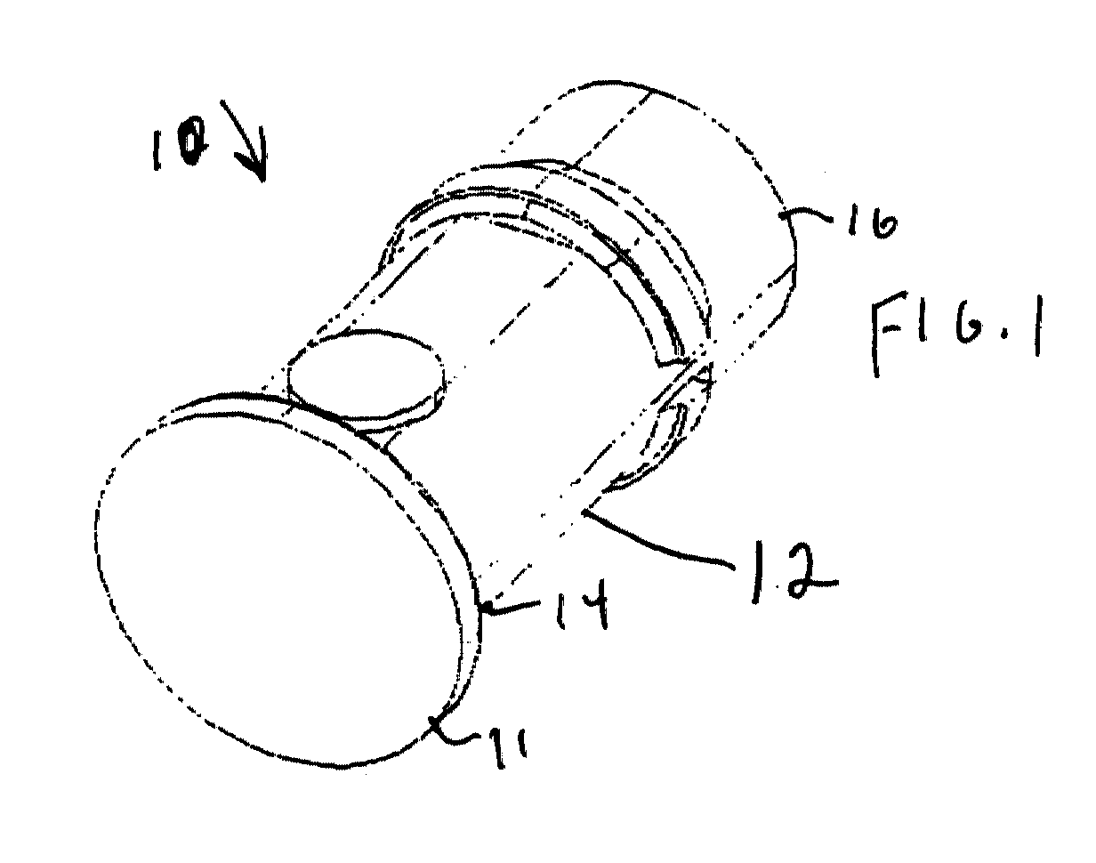
- Fig. 1 shows a perspective view of the lightpipe according to the present invention.
- Fig. 2 shows an exploded perspective view of the lightpipe of Fig. 1.
- Fig. 3 shows a representation of a test set-up for the lightpipe of Figs. 1 and 2.
-
- Figs. 1 and 2 show a lightpipe structure 10 formed of a hollow,
elongated lightpipe 12. A light source, such as an infrared remote control (not shown), emits light into an ingress end 14 oflightpipe 12 with a thin material 11 covering the ingress end 14. The infrared energy is channeled parallel to the longitudinal axis oflightpipe 12 and exits ategress end 16. The energy leaving egress end 16 impinges upon an infrared sensitive sensing device (not shown), e.g., a photodiode, phototransistor, photocell, or the like. The infrared energy emitting remote control, and the infrared sensitive sensing device along with the control circuitry therewith, form no part of the present invention and are only discussed herein in order to more fully disclose and/or claim the present invention. - More particularly, the present invention combines the best results of a thin IR crystal 11, and the throughput of the sheet
metal IR conduit 12. The lightpipe is made up of two parts: a crystal 11, which is made from a dark transparent polycarbonate material, and aconduit lightpipe portion 12, which in the exemplary embodiment is made of tin-plated sheet metal formed into a hollow round tube. The crystal 11 includes a portion 11 a which fits inside of hollow/void 15 oflightpipe portion 12. The twopieces 11, 12 are then assembled and, in the exemplary embodiment, are staked together by a fully automated process in a sheet metal progressive die. - It is within the contemplation of the present invention that other suitable securements can be used, e.g., very close fit, gluing, heat welding, etc. In this manner, the lightpipe assembly becomes a one piece unitary unit that can be almost twice as long as the prior longest usable plastic body lightpipe. It is further within the contemplation of the present invention that ingress end 14 of
conduit 12 would fit within a complementary void (not shown) in crystal 11 and the two parts can similarly be secured together. It is within the contemplation of the present arrangement that a concentrating lens made of an appropriate material (not shown), can be used at theegress end 16 or somewhere in the light path betweenegress end 16 and the photosensitive infrared detecting device. - The crystal 11 is molded with a thin light entry wall, so that the infrared signal energy transmission will be in the range of 85% to 90%, e.g., 3 mm thick polycarbonate having a purple color. The inner reflecting surfaces 20 are subject to air with air being the propagation medium, so there is little throughput loss along the longitudinal length of the tube. Thus, the only losses that occur come from the light reflecting off of internal reflective walls 20 and this loss is minimized by using a smooth and/or polished material. Smooth bright tin-plated steel, which is a low cost commercial material and mechanically easy to work with, has been shown to provide excellent results. However, an aluminum, copper, glass, or plastic cylindrical section having an IR reflective internal surface 20 can also be used. Additionally, because the cross-sectional geometry of metal conduit/
reflector 12, 20 in the exemplary embodiment is circular, the photonic energy is efficiently transmitted along the longitudinal geometric axis and the coaxial optical axis of reflectingconduit 12. However, other cross-sectional geometries, e.g., oval, elliptical, rectangular or square, can be used. - It is desirable that the receptivity of the IR receiver meet certain requirements with a minimum IR output from the remote control using the lightpipe of the present invention. Such a test setup is shown in Fig. 3, where a remote control is calibrated with fresh batteries. It is desirable that the IR receiver be operable when receiving inputs from the remote control from up to 45 degrees off-axis in any direction.
- Testing has shown that the present lightpipe according to aspects of the present invention, provides at least equivalent performance on-axis and better performance at both vertical and horizontal off-axis angles than prior plastic body lightpipe designs. The construction of the lightpipe according to the present invention has permitted the construction of a lightpipe exceeding 40 mm in length with acceptable parameters. Additionally, not only does the present design improve performance, but because most of the material used is low cost tin-plated steel, it is also less expensive than other designs.
- Although the above description is presented using an IR remote control as the IR source, it is within the contemplation of the present arrangement that the IR source can be other than a remote control, e.g., a keyboard or other IR transmitting device, for coupling IR of control signals and/or information signals, to the receiver.
Claims (18)
- In an electronic device responsive to an infrared energy emitting device, a lightpipe comprising:means (10) for receiving the infrared energy from the emitting device and acting as a conduit for the received energy to impinge upon an infrared sensitive sensing device,said means (10) comprising an entry material portion (11) which is at least partially transmissive of infrared energy, and characterized bya lightpipe portion (12) having an energy ingress aperture (14) and an energy egress (16) aperture, the lightpipe portion being hollow and having an infrared energy reflecting inner surface (20), the ingress aperture (14) being able to receive the incoming energy and the egress aperture (16) being able to transmit the received infrared energy to impinge upon the infrared sensitive sensing device,the entry material portion (11,11a) being secured to the lightpipe portion and covering the ingress aperture (14).
- The lightpipe of claim 1 characterized in that the lightpipe portion is made of metal with the inner surface (20) plated with a highly reflective material.
- The lightpipe of claim 1 characterized in that the lightpipe portion (12) is made of plastic with the inner surface being highly reflective.
- The lightpipe of claim 2 characterized in that the lightpipe portion (12) is circular in cross-section.
- The lightpipe of claim 1 characterized in that the entry material portion(11,11a) is mechanically secured to the lightpipe portion.
- The lightpipe of claim 1 characterized in that the entry material portion is glued to the lightpipe portion.
- The lightpipe of claim 1 characterized in that the entry material portion is adhered to the lightpipe portion by the application of heat.
- The lightpipe of claim 1 characterized in that the entry material portion appears darkened when viewed by the human eye.
- The lightpipe of claim 1 characterized in that the entry material portion is securable to a front panel of the electronic device.
- The lightpipe of claim 1 characterized in that the egress aperture includes a lens disposed within the hollow body for concentrating the infrared energy onto the infrared energy sensing device.
- The lightpipe of claim 1 characterized in that the length of the lightpipe portion is along a longitudinal axis, and the energy ingress aperture and the energy egress aperture are disposed along a straight optical axis coaxial with the longitudinal axis.
- The lightpipe of claim 1 characterized in that the ingress and egress apertures are circular.
- The lightpipe of claim 1 characterized in that the entry material portion and the elongated lightpipe portion form a unitary structure.
- The device of claim 1 characterized in that the electronic device can be any of a television receiver with or without a video display, a DVD player, an FM receiver, a CD player or an audio system.
- The device of claim 2 characterized in that the lightpipe portion is made of tin-plated sheet metal.
- A lightpipe comprising:means (10) for receiving the infrared energy from a transmitter device and acting as a conduit for the received energy to impinge upon an infrared sensitive sensing device,said means (10) comprising an entry material portion (11.11a) which is at least partially transmissive of infrared energy, and characterized bya lightpipe portion (12) having an energy ingress aperture (14) and an energy egress aperture (16), the lightpipe portion (12) being hollow and having an infrared energy reflecting inner surface, the ingress aperture being able to receive the incoming energy and the egress aperture being able to transmit the received infrared energy to impinge upon the infrared sensitive sensing device,the entry material portion being secured to the lightpipe portion and covering the ingress aperture.
- A method for producing a light pipe comprising the steps of:providing a lightpipe portion (12) and a crystal portion (11,11a), and characterized bysecuring the lightpipe portion and the crystal portion to each other to form a unitary device.
- The method of claim 17 characterized in that the lightpipe portion is hollow and the crystal portion covers a light ingress aperture of the lightpipe portion.
Applications Claiming Priority (4)
| Application Number | Priority Date | Filing Date | Title |
|---|---|---|---|
| US21219700P | 2000-06-16 | 2000-06-16 | |
| US212197P | 2000-06-16 | ||
| US63914300A | 2000-08-15 | 2000-08-15 | |
| US639143 | 2000-08-15 |
Publications (2)
| Publication Number | Publication Date |
|---|---|
| EP1164366A2 true EP1164366A2 (en) | 2001-12-19 |
| EP1164366A3 EP1164366A3 (en) | 2004-02-04 |
Family
ID=26906871
Family Applications (1)
| Application Number | Title | Priority Date | Filing Date |
|---|---|---|---|
| EP01113055A Withdrawn EP1164366A3 (en) | 2000-06-16 | 2001-05-29 | Lightpipe for infrared reception by electronic devices |
Country Status (5)
| Country | Link |
|---|---|
| EP (1) | EP1164366A3 (en) |
| JP (1) | JP2002090555A (en) |
| KR (1) | KR20010113479A (en) |
| CN (1) | CN1330462A (en) |
| MX (1) | MXPA01006119A (en) |
Cited By (2)
| Publication number | Priority date | Publication date | Assignee | Title |
|---|---|---|---|---|
| US9049757B2 (en) | 2010-03-19 | 2015-06-02 | Koninklijke Philips N.V. | Light source selection |
| EP2597439B1 (en) * | 2011-09-02 | 2023-12-06 | Mikrowellen-Systeme MWS GmbH | Pressure vessel |
Families Citing this family (3)
| Publication number | Priority date | Publication date | Assignee | Title |
|---|---|---|---|---|
| JP4491773B2 (en) * | 2003-09-26 | 2010-06-30 | 三菱マテリアル株式会社 | Manufacturing method of liquid crystal panel |
| CN105158814B (en) * | 2014-05-30 | 2018-11-20 | 侯文婷 | In-pipe media probe and detector assembly |
| CN113008383B (en) * | 2021-03-22 | 2022-05-03 | 海南电网有限责任公司文昌供电局 | Integrated detection device of distribution station |
Family Cites Families (4)
| Publication number | Priority date | Publication date | Assignee | Title |
|---|---|---|---|---|
| CA2028352A1 (en) * | 1989-10-25 | 1991-04-26 | Kyung-Shik Lee | High temperature sensor |
| JPH08191493A (en) * | 1995-01-10 | 1996-07-23 | Sony Corp | Light receiving mechanism for remote operation |
| JPH09215069A (en) * | 1996-02-02 | 1997-08-15 | Funai Electric Co Ltd | Electric equipment with remote control light receiving section |
| JPH10243481A (en) * | 1997-03-03 | 1998-09-11 | Matsushita Electric Ind Co Ltd | REMOTE CONTROL SIGNAL RECEIVER AND ELECTRONIC EQUIPMENT WITH THE SAME |
-
2001
- 2001-05-29 EP EP01113055A patent/EP1164366A3/en not_active Withdrawn
- 2001-06-12 KR KR1020010032681A patent/KR20010113479A/en not_active Withdrawn
- 2001-06-15 JP JP2001181811A patent/JP2002090555A/en not_active Withdrawn
- 2001-06-15 MX MXPA01006119A patent/MXPA01006119A/en unknown
- 2001-06-18 CN CN01121706A patent/CN1330462A/en active Pending
Non-Patent Citations (1)
| Title |
|---|
| None |
Cited By (2)
| Publication number | Priority date | Publication date | Assignee | Title |
|---|---|---|---|---|
| US9049757B2 (en) | 2010-03-19 | 2015-06-02 | Koninklijke Philips N.V. | Light source selection |
| EP2597439B1 (en) * | 2011-09-02 | 2023-12-06 | Mikrowellen-Systeme MWS GmbH | Pressure vessel |
Also Published As
| Publication number | Publication date |
|---|---|
| JP2002090555A (en) | 2002-03-27 |
| EP1164366A3 (en) | 2004-02-04 |
| MXPA01006119A (en) | 2004-11-10 |
| CN1330462A (en) | 2002-01-09 |
| KR20010113479A (en) | 2001-12-28 |
Similar Documents
| Publication | Publication Date | Title |
|---|---|---|
| US6502970B1 (en) | Vehicular puddle light | |
| US4792685A (en) | Photoelectric sensor | |
| US7920069B2 (en) | Audible, piezoelectric signal with integral visual signal | |
| US6477391B1 (en) | Mobile telephone holding device | |
| US20070165232A1 (en) | Optical sensor device | |
| US20040263825A1 (en) | Measuring device for contactless distance measurement | |
| JP2007225600A5 (en) | ||
| EP1724568A3 (en) | Optoelectronic sensor device | |
| KR20010113479A (en) | Lightpipe for infrared reception by electronic devices | |
| CN215910837U (en) | Frame, face frame subassembly and mutual dull and stereotyped | |
| JP3777590B2 (en) | Optical transceiver | |
| JP3106189U (en) | Structure of remote control receiver | |
| JP2004012647A (en) | Transceiver integrated optical module | |
| EP1347324A3 (en) | Signal receiver having light guide for guiding light transmitted from remote control | |
| JP2005073132A (en) | Electronic device and display device | |
| JP3565253B2 (en) | Mounting structure of infrared light guide member | |
| JPH07212318A (en) | Vehicle transceiver | |
| CN221303760U (en) | Display and display device | |
| CN217884125U (en) | Terminal equipment | |
| JPH11174269A (en) | Light guide unit and small electronic equipment | |
| CN211289705U (en) | Lamp ring subassembly for food processing machine | |
| CN218525178U (en) | Linear light beam smoke fire detector | |
| EP4556422A1 (en) | Housing of a yarn clearer and corresponding method of assembly | |
| JP2004320304A (en) | Case structure of remote control light-receiving electronics | |
| CN223740159U (en) | Inductor and induction tap |
Legal Events
| Date | Code | Title | Description |
|---|---|---|---|
| PUAI | Public reference made under article 153(3) epc to a published international application that has entered the european phase |
Free format text: ORIGINAL CODE: 0009012 |
|
| AK | Designated contracting states |
Kind code of ref document: A2 Designated state(s): AT BE CH CY DE DK ES FI FR GB GR IE IT LI LU MC NL PT SE TR |
|
| AX | Request for extension of the european patent |
Free format text: AL;LT;LV;MK;RO;SI |
|
| PUAL | Search report despatched |
Free format text: ORIGINAL CODE: 0009013 |
|
| AK | Designated contracting states |
Kind code of ref document: A3 Designated state(s): AT BE CH CY DE DK ES FI FR GB GR IE IT LI LU MC NL PT SE TR |
|
| AX | Request for extension of the european patent |
Extension state: AL LT LV MK RO SI |
|
| RIC1 | Information provided on ipc code assigned before grant |
Ipc: 7H 04Q 9/00 B Ipc: 7G 01J 5/08 A |
|
| STAA | Information on the status of an ep patent application or granted ep patent |
Free format text: STATUS: THE APPLICATION IS DEEMED TO BE WITHDRAWN |
|
| 18D | Application deemed to be withdrawn |
Effective date: 20031202 |