EP1164339A1 - Air conditioner - Google Patents
Air conditioner Download PDFInfo
- Publication number
- EP1164339A1 EP1164339A1 EP00906611A EP00906611A EP1164339A1 EP 1164339 A1 EP1164339 A1 EP 1164339A1 EP 00906611 A EP00906611 A EP 00906611A EP 00906611 A EP00906611 A EP 00906611A EP 1164339 A1 EP1164339 A1 EP 1164339A1
- Authority
- EP
- European Patent Office
- Prior art keywords
- air
- room
- moisture
- outdoors
- primary
- Prior art date
- Legal status (The legal status is an assumption and is not a legal conclusion. Google has not performed a legal analysis and makes no representation as to the accuracy of the status listed.)
- Granted
Links
- 239000003463 adsorbent Substances 0.000 claims abstract description 25
- 239000007787 solid Substances 0.000 claims abstract description 25
- 239000007788 liquid Substances 0.000 claims description 63
- 238000004378 air conditioning Methods 0.000 claims description 59
- 239000002250 absorbent Substances 0.000 claims description 50
- 230000002745 absorbent Effects 0.000 claims description 50
- 238000010438 heat treatment Methods 0.000 claims description 40
- 238000001816 cooling Methods 0.000 claims description 35
- 239000012528 membrane Substances 0.000 claims description 35
- XLYOFNOQVPJJNP-UHFFFAOYSA-N water Substances O XLYOFNOQVPJJNP-UHFFFAOYSA-N 0.000 claims description 35
- 230000002209 hydrophobic effect Effects 0.000 claims description 15
- 150000004820 halides Chemical class 0.000 claims description 6
- 150000002894 organic compounds Chemical class 0.000 claims description 6
- 238000001704 evaporation Methods 0.000 claims description 5
- 230000008020 evaporation Effects 0.000 claims description 5
- 229910052809 inorganic oxide Inorganic materials 0.000 claims description 5
- 238000010521 absorption reaction Methods 0.000 description 25
- 238000010276 construction Methods 0.000 description 24
- 238000007791 dehumidification Methods 0.000 description 17
- 238000010586 diagram Methods 0.000 description 10
- 238000009423 ventilation Methods 0.000 description 10
- LYCAIKOWRPUZTN-UHFFFAOYSA-N Ethylene glycol Chemical compound OCCO LYCAIKOWRPUZTN-UHFFFAOYSA-N 0.000 description 6
- 230000000694 effects Effects 0.000 description 6
- PEDCQBHIVMGVHV-UHFFFAOYSA-N Glycerine Chemical compound OCC(O)CO PEDCQBHIVMGVHV-UHFFFAOYSA-N 0.000 description 4
- AMXOYNBUYSYVKV-UHFFFAOYSA-M lithium bromide Chemical compound [Li+].[Br-] AMXOYNBUYSYVKV-UHFFFAOYSA-M 0.000 description 4
- KWGKDLIKAYFUFQ-UHFFFAOYSA-M lithium chloride Chemical compound [Li+].[Cl-] KWGKDLIKAYFUFQ-UHFFFAOYSA-M 0.000 description 4
- 239000012466 permeate Substances 0.000 description 4
- 238000011144 upstream manufacturing Methods 0.000 description 4
- 239000012530 fluid Substances 0.000 description 3
- UXVMQQNJUSDDNG-UHFFFAOYSA-L Calcium chloride Chemical compound [Cl-].[Cl-].[Ca+2] UXVMQQNJUSDDNG-UHFFFAOYSA-L 0.000 description 2
- 239000001110 calcium chloride Substances 0.000 description 2
- 229910001628 calcium chloride Inorganic materials 0.000 description 2
- 230000006835 compression Effects 0.000 description 2
- 238000007906 compression Methods 0.000 description 2
- 230000001143 conditioned effect Effects 0.000 description 2
- 235000011187 glycerol Nutrition 0.000 description 2
- 150000002484 inorganic compounds Chemical class 0.000 description 2
- 229910010272 inorganic material Inorganic materials 0.000 description 2
- 239000011347 resin Substances 0.000 description 2
- 229920005989 resin Polymers 0.000 description 2
- 230000015556 catabolic process Effects 0.000 description 1
- 150000001875 compounds Chemical class 0.000 description 1
- 238000009833 condensation Methods 0.000 description 1
- 230000005494 condensation Effects 0.000 description 1
- 230000003247 decreasing effect Effects 0.000 description 1
- 238000006731 degradation reaction Methods 0.000 description 1
- 230000002708 enhancing effect Effects 0.000 description 1
- 239000002075 main ingredient Substances 0.000 description 1
- 230000004048 modification Effects 0.000 description 1
- 238000012986 modification Methods 0.000 description 1
- 239000011148 porous material Substances 0.000 description 1
- 238000005057 refrigeration Methods 0.000 description 1
- 230000008929 regeneration Effects 0.000 description 1
- 238000011069 regeneration method Methods 0.000 description 1
Images





Classifications
-
- F—MECHANICAL ENGINEERING; LIGHTING; HEATING; WEAPONS; BLASTING
- F24—HEATING; RANGES; VENTILATING
- F24F—AIR-CONDITIONING; AIR-HUMIDIFICATION; VENTILATION; USE OF AIR CURRENTS FOR SCREENING
- F24F3/00—Air-conditioning systems in which conditioned primary air is supplied from one or more central stations to distributing units in the rooms or spaces where it may receive secondary treatment; Apparatus specially designed for such systems
- F24F3/12—Air-conditioning systems in which conditioned primary air is supplied from one or more central stations to distributing units in the rooms or spaces where it may receive secondary treatment; Apparatus specially designed for such systems characterised by the treatment of the air otherwise than by heating and cooling
- F24F3/14—Air-conditioning systems in which conditioned primary air is supplied from one or more central stations to distributing units in the rooms or spaces where it may receive secondary treatment; Apparatus specially designed for such systems characterised by the treatment of the air otherwise than by heating and cooling by humidification; by dehumidification
- F24F3/1411—Air-conditioning systems in which conditioned primary air is supplied from one or more central stations to distributing units in the rooms or spaces where it may receive secondary treatment; Apparatus specially designed for such systems characterised by the treatment of the air otherwise than by heating and cooling by humidification; by dehumidification by absorbing or adsorbing water, e.g. using an hygroscopic desiccant
- F24F3/1423—Air-conditioning systems in which conditioned primary air is supplied from one or more central stations to distributing units in the rooms or spaces where it may receive secondary treatment; Apparatus specially designed for such systems characterised by the treatment of the air otherwise than by heating and cooling by humidification; by dehumidification by absorbing or adsorbing water, e.g. using an hygroscopic desiccant with a moving bed of solid desiccants, e.g. a rotary wheel supporting solid desiccants
-
- F—MECHANICAL ENGINEERING; LIGHTING; HEATING; WEAPONS; BLASTING
- F24—HEATING; RANGES; VENTILATING
- F24F—AIR-CONDITIONING; AIR-HUMIDIFICATION; VENTILATION; USE OF AIR CURRENTS FOR SCREENING
- F24F5/00—Air-conditioning systems or apparatus not covered by F24F1/00 or F24F3/00, e.g. using solar heat or combined with household units such as an oven or water heater
- F24F5/0085—Systems using a compressed air circuit
-
- B—PERFORMING OPERATIONS; TRANSPORTING
- B64—AIRCRAFT; AVIATION; COSMONAUTICS
- B64D—EQUIPMENT FOR FITTING IN OR TO AIRCRAFT; FLIGHT SUITS; PARACHUTES; ARRANGEMENT OR MOUNTING OF POWER PLANTS OR PROPULSION TRANSMISSIONS IN AIRCRAFT
- B64D13/00—Arrangements or adaptations of air-treatment apparatus for aircraft crew or passengers, or freight space
-
- F—MECHANICAL ENGINEERING; LIGHTING; HEATING; WEAPONS; BLASTING
- F24—HEATING; RANGES; VENTILATING
- F24F—AIR-CONDITIONING; AIR-HUMIDIFICATION; VENTILATION; USE OF AIR CURRENTS FOR SCREENING
- F24F3/00—Air-conditioning systems in which conditioned primary air is supplied from one or more central stations to distributing units in the rooms or spaces where it may receive secondary treatment; Apparatus specially designed for such systems
- F24F3/12—Air-conditioning systems in which conditioned primary air is supplied from one or more central stations to distributing units in the rooms or spaces where it may receive secondary treatment; Apparatus specially designed for such systems characterised by the treatment of the air otherwise than by heating and cooling
- F24F3/14—Air-conditioning systems in which conditioned primary air is supplied from one or more central stations to distributing units in the rooms or spaces where it may receive secondary treatment; Apparatus specially designed for such systems characterised by the treatment of the air otherwise than by heating and cooling by humidification; by dehumidification
- F24F3/1411—Air-conditioning systems in which conditioned primary air is supplied from one or more central stations to distributing units in the rooms or spaces where it may receive secondary treatment; Apparatus specially designed for such systems characterised by the treatment of the air otherwise than by heating and cooling by humidification; by dehumidification by absorbing or adsorbing water, e.g. using an hygroscopic desiccant
- F24F3/1417—Air-conditioning systems in which conditioned primary air is supplied from one or more central stations to distributing units in the rooms or spaces where it may receive secondary treatment; Apparatus specially designed for such systems characterised by the treatment of the air otherwise than by heating and cooling by humidification; by dehumidification by absorbing or adsorbing water, e.g. using an hygroscopic desiccant with liquid hygroscopic desiccants
-
- B—PERFORMING OPERATIONS; TRANSPORTING
- B64—AIRCRAFT; AVIATION; COSMONAUTICS
- B64D—EQUIPMENT FOR FITTING IN OR TO AIRCRAFT; FLIGHT SUITS; PARACHUTES; ARRANGEMENT OR MOUNTING OF POWER PLANTS OR PROPULSION TRANSMISSIONS IN AIRCRAFT
- B64D13/00—Arrangements or adaptations of air-treatment apparatus for aircraft crew or passengers, or freight space
- B64D13/06—Arrangements or adaptations of air-treatment apparatus for aircraft crew or passengers, or freight space the air being conditioned
- B64D2013/0603—Environmental Control Systems
- B64D2013/0662—Environmental Control Systems with humidity control
-
- F—MECHANICAL ENGINEERING; LIGHTING; HEATING; WEAPONS; BLASTING
- F24—HEATING; RANGES; VENTILATING
- F24F—AIR-CONDITIONING; AIR-HUMIDIFICATION; VENTILATION; USE OF AIR CURRENTS FOR SCREENING
- F24F2203/00—Devices or apparatus used for air treatment
- F24F2203/02—System or Device comprising a heat pump as a subsystem, e.g. combined with humidification/dehumidification, heating, natural energy or with hybrid system
- F24F2203/026—Absorption - desorption cycle
- F24F2203/028—Absorption - desorption cycle using a solid absorbing medium
-
- F—MECHANICAL ENGINEERING; LIGHTING; HEATING; WEAPONS; BLASTING
- F24—HEATING; RANGES; VENTILATING
- F24F—AIR-CONDITIONING; AIR-HUMIDIFICATION; VENTILATION; USE OF AIR CURRENTS FOR SCREENING
- F24F2203/00—Devices or apparatus used for air treatment
- F24F2203/10—Rotary wheel
- F24F2203/1016—Rotary wheel combined with another type of cooling principle, e.g. compression cycle
-
- F—MECHANICAL ENGINEERING; LIGHTING; HEATING; WEAPONS; BLASTING
- F24—HEATING; RANGES; VENTILATING
- F24F—AIR-CONDITIONING; AIR-HUMIDIFICATION; VENTILATION; USE OF AIR CURRENTS FOR SCREENING
- F24F2203/00—Devices or apparatus used for air treatment
- F24F2203/10—Rotary wheel
- F24F2203/1032—Desiccant wheel
-
- F—MECHANICAL ENGINEERING; LIGHTING; HEATING; WEAPONS; BLASTING
- F24—HEATING; RANGES; VENTILATING
- F24F—AIR-CONDITIONING; AIR-HUMIDIFICATION; VENTILATION; USE OF AIR CURRENTS FOR SCREENING
- F24F2203/00—Devices or apparatus used for air treatment
- F24F2203/10—Rotary wheel
- F24F2203/1056—Rotary wheel comprising a reheater
-
- F—MECHANICAL ENGINEERING; LIGHTING; HEATING; WEAPONS; BLASTING
- F24—HEATING; RANGES; VENTILATING
- F24F—AIR-CONDITIONING; AIR-HUMIDIFICATION; VENTILATION; USE OF AIR CURRENTS FOR SCREENING
- F24F2203/00—Devices or apparatus used for air treatment
- F24F2203/10—Rotary wheel
- F24F2203/1068—Rotary wheel comprising one rotor
-
- F—MECHANICAL ENGINEERING; LIGHTING; HEATING; WEAPONS; BLASTING
- F24—HEATING; RANGES; VENTILATING
- F24F—AIR-CONDITIONING; AIR-HUMIDIFICATION; VENTILATION; USE OF AIR CURRENTS FOR SCREENING
- F24F2203/00—Devices or apparatus used for air treatment
- F24F2203/10—Rotary wheel
- F24F2203/1084—Rotary wheel comprising two flow rotor segments
-
- Y—GENERAL TAGGING OF NEW TECHNOLOGICAL DEVELOPMENTS; GENERAL TAGGING OF CROSS-SECTIONAL TECHNOLOGIES SPANNING OVER SEVERAL SECTIONS OF THE IPC; TECHNICAL SUBJECTS COVERED BY FORMER USPC CROSS-REFERENCE ART COLLECTIONS [XRACs] AND DIGESTS
- Y02—TECHNOLOGIES OR APPLICATIONS FOR MITIGATION OR ADAPTATION AGAINST CLIMATE CHANGE
- Y02T—CLIMATE CHANGE MITIGATION TECHNOLOGIES RELATED TO TRANSPORTATION
- Y02T50/00—Aeronautics or air transport
- Y02T50/50—On board measures aiming to increase energy efficiency
Definitions
- This invention relates to an air conditioning system using an air cycle.
- a cooling system operating through an air cycle includes a compressor, a heat exchanger and an expander, and is configured to suck an air into the compressor for compression, cool the compressed air in the heat exchanger and then expand it in the expander thereby obtaining a low-temperature air.
- a vapor isolating device using a vapor isolating membrane is provided between the heat exchanger and the expander to isolate moisture from the compressed air being supplied to the expander.
- the air Once expanded in the expander, the air is reduced in temperature so that dropwise condensation may occur in the air. Therefore, the air as a working fluid for the air cycle is needed to undergo dehumidification prior to entry into the expander.
- the vapor isolating device is provided in place to dehumidify the compressed air.
- the cooling system as described above accomplishes dehumidification by using the vapor isolating membrane
- the air as a working fluid for the air cycle can only be dehumidified between the compressor and the expander.
- moisture in the air permeates the vapor isolating membrane, i.e., moves from the air on one side of the vapor isolating membrane to that on the other side.
- the moisture in the air permeates the vapor isolating membrane with a difference between vapor partial pressures in the airs on both sides of the isolating membrane.
- the air from which moisture moves must always be held at a higher vapor partial pressure than that to which moisture moves, and therefore there has been nothing for means for dehumidification but to be provided in a place where the vapor partial pressure of the air from which moisture moves will be high, i.e., between the compressor and the expander.
- any component for dehumidifying the air should be rather large in size. This is because a certain degree or more of contact area with the air to be dehumidified must be ensured. Therefore, there arises the problem that limitation of placement of such a relatively large component would incur degradation in design flexibility of the overall system.
- the present invention has been made in view of such problems and therefore aims at enhancing the design flexibility and providing simplified construction while keeping high efficiency.
- the present invention provides for carrying out dehumidification of the air as a working fluid for the air cycle with the use of a humidity medium for absorbing and releasing moisture through contact with the air prior to supply of the air to the compressor.
- a first solution taken in the present invention is directed to an air conditioning system for effecting air conditioning in an air cycle comprising a compressor (21) , a heat exchanger (30) and an expander (22). Further, provided in this system is dehumidifying means (60) that includes a humidity medium for absorbing and releasing moisture through contact with an air and allows the humidity medium to absorb moisture in a primary air to be supplied to the compressor (21) while releasing the moisture therein to a secondary air thereby continuously dehumidifying the primary air.
- the heat exchanger (30) is arranged to cool the compressed primary air through heat exchange with the secondary air, and the dehumidifying means (60) is arranged to release moisture in the humidity medium to the secondary air coming from the heat exchanger (30).
- the humidity medium of the dehumidifying means (60) is provided with a solid adsorbent for adsorbing moisture.
- the humidity medium of the dehumidifying means (60) is formed of a rotor member (61) that is formed in the shape of a disc to allow air passage in a direction of its thickness and provides contact of the passing air with the solid adsorbent
- the dehumidifying means (60) comprises a moisture absorbing section (62) where the rotor member (61) absorbs moisture in the primary air through contact with the primary air, a moisture releasing section (63) where the rotor member (61) releases moisture therein to the secondary air through contact with the secondary air, and a drive mechanism for rotatively driving the rotor member (61) to allow the rotor member (61) to move between the moisture absorbing section (62) and the moisture releasing section (63) .
- the solid adsorbent is made of porous inorganic oxide.
- the humidity medium of the dehumidifying means (60) comprises a liquid absorbent for absorbing moisture.
- the humidity medium of the dehumidifying means (60) comprises a liquid absorbent for absorbing moisture, and the dehumidifying means (60) is arranged so that the liquid absorbent is heated by the primary air coming from the compressor (21) to release moisture having absorbed from the primary air to the secondary air.
- the dehumidifying means (60) includes a moisture-permeable, hydrophobic porous membrane and is arranged to contact the liquid absorbent with the primary air through the hydrophobic porous membrane.
- the liquid absorbent is made of a water solution of hydrophilic organic compound.
- the liquid absorbent is made of a water solution of metallic halide.
- the dehumidifying means (60) comprises a circulation circuit (64) that includes a moisture absorbing section (65) for contacting the liquid absorbent with the primary air and a moisture releasing section (66) for contacting the liquid absorbent with the secondary air and circulates the liquid absorbent between the moisture absorbing section (65) and the moisture releasing section (66).
- cooling of a room is effected by supplying the primary air expanded in the expander (22) to the room.
- the primary air is an outside air taken from outdoors and then supplied to the room through the expander (22), while the secondary air is a room air taken from the room and then discharged to outdoors through the dehumidifying means (60).
- the primary air is an outside air taken from outdoors and then supplied to the room through the expander (22)
- the secondary air is an outside air taken from outdoors and then discharged to outdoors through the dehumidifying means (60).
- the primary air is a room air taken from the room and then supplied to the room through the expander (22)
- the secondary air is a room air taken from the room and then discharged to outdoors through the dehumidifying means (60) .
- the primary air is a room air taken from the room and then supplied to the room through the expander (22)
- the secondary air is an outside air taken from outdoors and then discharged to outdoors through the dehumidifying means (60) .
- the primary air is a mixed air of a room air taken from the room and an outside air taken from outdoors and is supplied to the room through the expander (22)
- the secondary air is a room air taken from the room and then discharged to outdoors through the dehumidifying means (60).
- the primary air is a mixed air of a room air taken from the room and an outside air taken from outdoors and is supplied to the room through the expander (22) , while the secondary air is an outside air taken from outdoors and then discharged to outdoors through the dehumidifying means (60).
- the primary air is a mixed air of a room air taken from the room and an outside air taken from outdoors and is supplied to the room through the expander (22)
- the secondary air is a mixed air of a room air taken from the room and an outside air taken from outdoors and is discharged to outdoors through the dehumidifying means (60) .
- a twentieth solution taken in the present invention is, based on the twelfth solution, provided with preheating means (33) for heating the primary air dehumidified by the dehumidifying means (60) through heat exchange with the primary air compressed by the compressor (21) and then supplying the primary air to the compressor (21).
- a twenty-first solution taken in the present invention is, based on the twelfth solution, provided with preheating means (33) for heating the primary air dehumidified by the dehumidifying means (60) through heat exchange with part of the primary air compressed by the compressor (21) and then supplying the primary air to the compressor (21) .
- a twenty-second solution taken in the present invention is, based on any one of the twelfth to twenty-first solutions, provided with moisture supplying means (41) for supplying moisture to the secondary air not yet supplied to the heat exchanger (30) in order to humidify and cool the secondary air.
- a twenty-third solution taken in the present invention is, based on any one of the twelfth to twenty-first solutions, provided with moisture supplying means (42) for supplying moisture to the secondary air in the heat exchanger (30) in order to use latent heat of evaporation of water to cool the primary air in the heat exchanger (30) .
- the moisture supplying means (41, 42) is arranged to supply moisture to the secondary air through a permeable membrane capable of permeating moisture.
- heating of a room is effected by supplying the secondary air heated through heat exchange with the primary air in the heat exchanger (30) to the room.
- the primary air is a room air taken from the room and then discharged to outdoors through the expander (22)
- the secondary air is an outside air taken from outdoors and then supplied to the room through the dehumidifying means (60).
- the primary air is an outside air taken from outdoors and then discharged to outdoors through the expander (22)
- the secondary air is an outside air taken from outdoors and then supplied to the room through the dehumidifying means (60) .
- the primary air is a room air taken from the room and then discharged to outdoors through the expander (22)
- the secondary air is a room air taken from the room and then supplied to the room through the dehumidifying means (60).
- the primary air is an outside air taken from outdoors and then discharged to outdoors through the expander (22)
- the secondary air is a room air taken from the room and then supplied to the room through the dehumidifying means (60) .
- the primary air is a room air taken from the room and then discharged to outdoors through the expander (22)
- the secondary air is a mixed air of a room air taken from the room and an outside air taken from outdoors and is supplied to the room through the dehumidifying means (60) .
- the primary air is an outside air taken from outdoors and then discharged to outdoors through the expander (22)
- the secondary air is a mixed air of a room air taken from the room and an outside air taken from outdoors and is supplied to the room through the dehumidifying means (60) .
- the primary air is a mixed air of a room air taken from the room and an outside air taken from outdoors and is discharged to outdoors through the expander (22)
- the secondary air is a mixed air of a room air taken from the room and an outside air taken from outdoors and is supplied to the room through the dehumidifying means (60).
- a thirty-third solution taken in the present invention is, based on the second solution, provided with selector means (71, 72) for taking in different airs as the primary and secondary airs for each of cooling and heating operations and selecting the primary air from the expander (22) and the secondary air from the dehumidifying means (60) to supply them to the room to thereby allow both the cooling and heating operations.
- a thirty-fourth solution taken in the present invention is, based on the thirty-third solution, provided with preheating means (33) for heating the primary air dehumidified by the dehumidifying means (60) through heat exchange with the primary air compressed by the compressor (21) and then supplying the primary air to the compressor (21) , and bypassing means (73) for allowing the primary air to bypass the preheating means (33) and to be supplied directly to the compressor (21) during the heating operation.
- a thirty-fifth solution taken in the present invention is, based on the thirty-third solution, provided with preheating means (33) for heating the primary air dehumidified by the dehumidifying means (60) through heat exchange with part of the primary air compressed by the compressor (21) and then supplying the primary air to the compressor (21) , and bypassing means (73) for allowing the primary air to bypass the preheating means (33) and to be supplied directly to the compressor (21) during the heating operation.
- the primary air is supplied to the compressor (22) and so compressed therein as to reach a high temperature.
- the high-temperature primary air is cooled in the heat exchanger (30) and then so expanded by the expander (22) as to reach a low temperature.
- This compressor (21) is supplied with the primary air dehumidified by the dehumidifying means (60). Cooling the room is provided by supplying the low-temperature primary air to the room, while heating the room is provided by using heat release from the primary air in the heat exchanger (30) .
- the humidity medium of the dehumidifying means (60) absorbs moisture in the primary air and releases the absorbed moisture to the secondary air. In other words, the moisture in the primary air is transferred to the secondary air through the humidity medium. During the time, if the relative humidity of the primary air is high to some extent, the humidity medium absorbs moisture. On the other hand, if the relative humidity of the secondary air is low to some extent, the humidity medium releases moisture. Accordingly, even if the primary and secondary airs have equal vapor partial pressures or equal absolute humidities, a difference in relative humidity between both the airs would cause moisture transfer through the humidity medium.
- the primary air from the compressor (21) is cooled through heat exchange with the secondary air and then flows toward the expander (22) .
- the humidity medium of the dehumidifying means (60) releases moisture to the secondary air heated in the heat exchanger (30) .
- the humidity medium releases moisture to the secondary air elevated in temperature and reduced in relative humidity through heat application as a result of heat exchange with the primary air.
- the humidity medium absorbs moisture in such a manner that the moisture is adsorbed on the solid adsorbent. Further, the humidity medium releases moisture in such a manner that the moisture is desorbed from the solid adsorbent.
- the humidity medium is formed of a disc-shaped rotor member (61).
- a portion of the rotor member (61) absorbs moisture through contact with the primary air in the moisture absorbing section (62) .
- the rotor member (61) is rotatively driven by the drive mechanism so that the portion of the rotor member (61) which has absorbed moisture moves to the moisture releasing section (63).
- the rotor member (61) releases the moisture through contact with the secondary air.
- the rotor member (61) as the humidity medium is thereby regenerated. Thereafter, the portion of the rotor member (61) which has been regenerated moves to the moisture absorbing section (62) again and repeats these actions.
- the solid adsorbent is made of porous inorganic oxide. It is to be noted that the solid adsorbent may be made of particular inorganic oxide alone or may include the inorganic oxide as a main ingredient.
- the humidity medium absorbs moisture in such a manner that the moisture is absorbed in the liquid absorbent. Further, the humidity medium releases moisture in such a manner that the moisture is desorbed from the liquid absorbent.
- the liquid absorbent absorbs moisture from the primary air not yet supplied to the compressor (21) .
- This liquid absorbent is heated up into an easy-to-release condition by the high-temperature primary air compressed by the compressor (21) , and then released to the secondary air. This moisture release regenerates the liquid absorbent.
- the primary air and the liquid absorbent come into indirect contact with each other through the hydrophobic porous membrane interposed therebetween.
- the moisture in the primary air permeates the hydrophobic porous membrane and is then absorbed in the liquid absorbent, whereby the primary air is dehumidified.
- the liquid absorbent is made of a water solution of hydrophilic organic compound.
- organic compound of this kind include ethylene glycol, glycerin and hydrophilic resin.
- the liquid absorbent is made of a water solution of metallic halide.
- metallic halide of this kind include LiCl, LiBr and CaCl 2 .
- the liquid absorbent absorbs moisture of the primary air in the moisture absorbing section (65) , whereby the primary air is dehumidified.
- This liquid absorbent flows through the circulation circuit (64) to reach the moisture releasing section (66) .
- the liquid absorbent releases moisture to the secondary air and is thereby regenerated.
- the regenerated liquid absorbent flows through the circulation circuit (64) to reach the moisture absorbing section (65) again, and repeats this circulation.
- the primary air expanded in the expander (22) to reach a low temperature is supplied to the room, thereby cooling the room.
- an outside air is supplied as the primary air to the dehumidifying means (60) .
- This outside air is dehumidified by the dehumidifying means (60) , supplied to the compressor (21) , sequentially flows through the compressor (21) , the heat exchanger (30) and the expander (22) to reach a low temperature, and is then supplied to the room.
- a room air is supplied as the secondary air to the heat exchanger (30) . This room air passes through the heat exchanger (30) , flows into the dehumidifying means (60) , takes moisture from the dehumidifying means (60) , and is then discharged to outdoors.
- an outside air is supplied as the primary air to the dehumidifying means (60) .
- This outside air is dehumidified by the dehumidifying means (60) , is supplied to the compressor (21) , sequentially flows through the compressor (21) , the heat exchanger (30) and the expander (22) to reach a low temperature, and is then supplied to the room.
- another outside air is also supplied as the secondary air to the heat exchanger (30) . This outside air passes through the heat exchanger (30) , flows into the dehumidifying means (60) , takes moisture from the dehumidifying means (60) , and is then discharged to outdoors again.
- a room air is supplied as the primary air to the dehumidifying means (60) .
- This room air is dehumidified by the dehumidifying means (60) , is supplied to the compressor (21) , sequentially flows through the compressor (21) , the heat exchanger (30) and the expander (22) to reach a low temperature, and is then supplied to the room again.
- another room air is also supplied as the secondary air to the heat exchanger (30) .
- This room air passes through the heat exchanger (30) , flows into the dehumidifying means (60) , takes moisture from the dehumidifying means (60) , and is then discharged to outdoors.
- a room air is supplied as the primary air to the dehumidifying means (60) .
- This room air is dehumidified by the dehumidifying means (60) , is supplied to the compressor (21) , sequentially flows through the compressor (21) , the heat exchanger (30) and the expander (22) to reach a low temperature, and is then supplied to the room again.
- an outside air is supplied as the secondary air to the heat exchanger (30). This outside air passes through the heat exchanger (30), flows into the dehumidifying means (60) , takes moisture from the dehumidifying means (60) , and is then discharged to outdoors again.
- a mixed air of room and outside airs is supplied as the primary air to the dehumidifying means (60) .
- This mixed air is dehumidified by the dehumidifying means (60) , is supplied to the compressor (21) , sequentially flows through the compressor (21) , the heat exchanger (30) and the expander (22) to reach a low temperature, and is then supplied to the room.
- a room air is supplied as the secondary air to the heat exchanger (30) . This room air passes through the heat exchanger (30) , flows into the dehumidifying means (60) , takes moisture from the dehumidifying means (60) , and is then discharged to outdoors.
- a mixed air of room and outside airs is supplied as the primary air to the dehumidifying means (60) .
- This mixed air is dehumidified by the dehumidifying means (60) , is supplied to the compressor (21) , sequentially flows through the compressor (21) , the heat exchanger (30) and the expander (22) to reach a low temperature, and is then supplied to the room.
- an outside air is supplied as the secondary air to the heat exchanger (30) . This outside air passes through the heat exchanger (30) , flows into the dehumidifying means (60) , takes moisture from the dehumidifying means (60) , and is then discharged to outdoors again.
- a mixed air of room and outside airs is supplied as the primary air to the dehumidifying means (60) .
- This mixed air is dehumidified by the dehumidifying means (60) , is supplied to the compressor (21) , sequentially flows through the compressor (21) , the heat exchanger (30) and the expander (22) to reach a low temperature, and is then supplied to the room.
- another mixed air of room and outside airs is supplied as the secondary air to the heat exchanger (30) .
- This mixed air passes through the heat exchanger (30) , flows into the dehumidifying means (60) , takes moisture from the dehumidifying means (60) , and is then discharged to outdoors.
- the primary air is dehumidified by the dehumidifying means (60) , is preheated into a higher temperature condition by the preheating means (33) , and is then supplied in this condition to the compressor (21).
- the preheating means (33) in the twentieth solution
- part of the dehumidified primary air flows into the preheating means (33) in the twenty-first solution.
- the temperature of the primary air is higher at the inlet of the compressor (21), it will be elevated to a still higher temperature at the outlet of the compressor (21) .
- the temperature of the secondary air will also be elevated at the outlet of the heat exchanger (30) . Accordingly, the humidity medium of the dehumidifying means (60) will release moisture to the secondary air of higher temperature.
- moisture is supplied to the secondary air by the moisture supplying means (41) , and this moisture is then evaporated to cool the secondary air.
- This cooled secondary air is supplied to the heat exchanger (30) to exchange heat with the primary air.
- moisture is supplied to the secondary air in the heat exchanger (30) by the moisture supplying means (42) .
- the moisture supplying means (42) In the heat exchanger (30) , heat is exchanged between the secondary air and the primary air while moisture is evaporated in the secondary air. Then, latent heat of evaporation of water is used to cool the primary air.
- the moisture supplying means (41, 42) adequately supplies moisture to the secondary air through the permeable membrane. This ensures that the supplied moisture evaporates in the secondary air.
- the secondary air heat exchanged with the primary air in the heat exchanger (30) to reach a high temperature is supplied to the room, thereby heating the room.
- a room air is supplied as the primary air to the dehumidifying means (60).
- This room air is dehumidified by the dehumidifying means (60) , is supplied to the compressor (21) , sequentially flows through the compressor (21) , the heat exchanger (30) and the expander (22) , and is then discharged to outdoors.
- an outside air is supplied as the secondary air to the heat exchanger (30) .
- This outside air is heated up by passing through the heat exchanger (30) , flows into the dehumidifying means (60), is humidified by taking moisture from the dehumidifying means (60) , and is then supplied to the room.
- an outside air is supplied as the primary air to the dehumidifying means (60) .
- This outside air is dehumidified by the dehumidifying means (60) , is supplied to the compressor (21) , sequentially flows through the compressor (21) , the heat exchanger (30) and the expander (22) , and is then discharged to outdoors again.
- another outside air is also supplied as the secondary air to the heat exchanger (30) .
- This outside air is heated up by passing through the heat exchanger (30) , flows into the dehumidifying means (60) , is humidified by taking moisture from the dehumidifying means (60) , and is then supplied to the room.
- a room air is supplied as the primary air to the dehumidifying means (60) .
- This room air is dehumidified by the dehumidifying means (60) , is supplied to the compressor (21) , sequentially flows through the compressor (21) , the heat exchanger (30) and the expander (22), and is then discharged to outdoors.
- another room air is also supplied as the secondary air to the heat exchanger (30) .
- This room air is heated up by passing through the heat exchanger (30) , flows into the dehumidifying means (60) , is humidified by taking moisture from the dehumidifying means (60) , and is then supplied to the room again.
- an outside air is supplied as the primary air to the dehumidifying means (60).
- This outside air is dehumidified by the dehumidifying means (60) , is supplied to the compressor (21) , sequentially flows through the compressor (21) , the heat exchanger (30) and the expander (22) , and is then discharged to outdoors again.
- a room air is supplied as the secondary air to the heat exchanger (30) .
- This room air is heated up by passing through the heat exchanger (30) , flows into the dehumidifying means (60) , is humidified by taking moisture from the dehumidifying means (60) , and is then supplied to the room again.
- a room air is supplied as the primary air to the dehumidifying means (60) .
- This room air is dehumidified by the dehumidifying means (60) , is supplied to the compressor (21) , sequentially flows through the compressor (21) , the heat exchanger (30) and the expander (22) , and is then discharged to outdoors.
- a mixed air of room and outside airs is supplied as the secondary air to the heat exchanger (30). This mixed air is heated by passing through the heat exchanger (30) , flows into the dehumidifying means (60) , is humidified by taking moisture from the dehumidifying means (60) , and is then supplied to the room.
- an outside air is supplied as the primary air to the dehumidifying means (60) .
- This outside air is dehumidified by the dehumidifying means (60) , is supplied to the compressor (21) , sequentially flows through the compressor (21) , the heat exchanger (30) and the expander (22) , and is then discharged to outdoors.
- a mixed air of room and outside airs is supplied as the secondary air to the heat exchanger (30) . This mixed air is heated up by passing through the heat exchanger (30) , flows into the dehumidifying means (60) , is humidified by taking moisture from the dehumidifying means (60) , and is then supplied to the room.
- a mixed air of room and outside airs is supplied as the primary air to the dehumidifying means (60).
- This mixed air is dehumidified by the dehumidifying means (60) , is supplied to the compressor (21) , sequentially flows through the compressor (21) , the heat exchanger (30) and the expander (22) , and is then discharged to outdoors.
- another mixed air of room and outside airs is also supplied as the secondary air to the heat exchanger (30).
- This mixed air is heated up by passing through the heat exchanger (30) , flows into the dehumidifying means (60) , is humidified by taking moisture from the dehumidifying means (60), and is then supplied to the room.
- the primary and secondary airs are selected and supplied to the room by the selector means (71, 72) . Then, the low-temperature primary air expanded by the expander (22) is supplied to the room to cool it. Alternatively, the high-temperature secondary air heated in the heat exchanger (30) is supplied to the room to heat it. Further, the selector means (71, 72) allows the compressor (21) and the heat exchanger (30) to each take in a predetermined air depending upon the cooling or heating operation.
- the primary air is dehumidified by the dehumidifying means (60) , preheated into a higher temperature. condition by the preheating means (33) , and supplied in this condition to the compressor (21) .
- the preheating means (33) In the thirty-fourth and thirty-fifth solutions, during the cooling operation, the primary air is dehumidified by the dehumidifying means (60) , preheated into a higher temperature. condition by the preheating means (33) , and supplied in this condition to the compressor (21) .
- all of the dehumidified primary air flows into the preheating means (33) in the thirty-fourth solution, while part of the dehumidified primary air flows into the preheating means (33) in the thirty-fifth solution.
- the temperature of the primary air is higher at the inlet of the compressor (21) , it will be elevated to a still higher temperature at the outlet of the compressor (21) .
- the temperature of the secondary air will also be elevated at the outlet of the heat exchanger (30) . Accordingly, the humidity medium of the dehumidifying means (60) will release moisture to the secondary air of higher temperature.
- the primary air dehumidified by the dehumidifying means (60) is allowed to bypass the preheating means (33) by the bypassing means (73) and supplied directly to the compressor (21) in both the thirty-fourth and thirty-fifth solutions.
- dehumidification of the primary air can be implemented by moisture absorption and release of the humidity medium based on the difference in relative humidity between the primary and secondary airs. Specifically, if the relative humidity of the primary air is high to some extent, the humidity medium absorbs moisture. If the relative humidity of the secondary air is low to some extent, the humidity medium releases moisture. Accordingly, even if the primary and secondary airs have equal vapor partial pressures or equal absolute humidities, a difference in relative humidity between both the airs would cause moisture transfer through the humidity medium.
- dehumidification of the primary air is not limited to after it has been compressed by the compressor (21), unlike the case of dehumidifying it using the conventional vapor isolating membrane, and is possible also before it is supplied to the compressor (21) .
- layout constraints of the dehumidifying means (60) can be reduced, which enhances the design flexibility.
- the dehumidifying means (60) releases moisture, which it has taken up from the primary air, to the secondary air, this eliminates the need to dispose of the moisture as a drain. Therefore, any structure for drainage is not required, which simplifies the construction.
- moisture in the humidity medium can be released to the secondary air which has been reduced in relative humidity by the passage through the heat exchanger (30) .
- the secondary air in conducting the heating operation by supplying the secondary air from the humidity medium to the room, the secondary air can be humidified by the moisture removed from the primary air. Accordingly, energy of the moisture in the primary air can be recovered to the secondary air, which provides enhanced energy efficiency.
- the humidity medium of the dehumidifying means (60) can be formed using the solid adsorbent or the liquid absorbent. Particularly according to each of the fourth and eleventh solutions, the dehumidifying means (60) can be formed properly for each particular humidity medium.
- cooling of the room can be implemented by supplying to the room the primary air having reached a low temperature through the sequential passage through the compressor (21), the heat exchanger (30) and the expander (22).
- a room air or a mixed air containing the room air is supplied to the heat exchanger (30).
- the room air is lower in temperature than the outside air. Therefore, the primary air can be cooled to a still lower temperature in the heat exchanger (30) and therefore the air temperature at the inlet of the expander (22) can be reduced.
- moisture is supplied to the secondary air so that the primary air can be cooled to a still lower temperature in the heat exchanger (30) . Therefore, the air temperature at the inlet of the expander (22) can be reduced.
- each of the above solutions enables reduction in the input to the compressor (21) while maintaining the refrigerating capacity and thereby provides improved COP (coefficient of performance).
- the rooms In buildings or the like, the rooms must be not only air conditioned but also ventilated. In such a case, if an outside air is used as the primary air while a room air is used as the secondary air as in the thirteenth solution, the rooms can be ventilated while being cooled. Further, since the primary air is cooled by the room air as the secondary air in the heat exchanger (30) , cold heat can be recovered from the room air being discharged to outdoors for ventilation. As a result, energy loss involved in ventilation can be reduced.
- the temperature of the primary air to be supplied to the compressor (21) can be elevated to a higher degree as compared with the case where it is supplied thereto directly from the dehumidifying means (60) .
- the temperature of the secondary air at the outlet of the heat exchanger (30) can be correspondingly elevated.
- regeneration of the humidity medium can be achieved with certainty by the secondary air of higher temperature and low humidity.
- heating of the room can be implemented by supplying to the room the secondary air which has been heated up by the passage through the heat exchanger (30) and moisturized by the passage through the dehumidifying means (60).
- the rooms must be not only air conditioned but also ventilated.
- the rooms can be ventilated while being heated.
- the primary air of a room air and the secondary air to be supplied to the room are heat exchanged with each other in the heat exchanger (30) , hot heat can be recovered from the room air being discharged to outdoors for ventilation. As a result, energy loss involved in ventilation can be reduced.
- the cooling and heating operations can be selectively conducted.
- the bypass means (73) can allow the primary air to bypass the preheating means (33) for supply to the compressor (21).
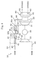
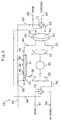
- an air conditioning system of this embodiment includes a first channel (21) , a second channel (20) and a dehumidifying mechanism (60) as a dehumidifying means, and is configured to provide cooling for a room.
- the first channel (20) is formed by sequentially connecting a compressor (21) , a heat exchanger (30) and an expander (22) through ducts, and is configured to allow a primary air to flow therethrough for air-cycle refrigeration.
- This first channel (20) includes a first inlet duct (23) connected to the inlet side of the compressor (21) , and a first outlet duct (24) connected to the outlet side of the expander (22) .
- the first inlet duct (23) is opened at one end thereof to outdoors to take in an outside air as the primary air.
- the first outlet duct (24) is opened at one end thereof to the room to introduce the low-temperature primary air coming from the expander (22) into the room.
- the second channel (40) is formed by connecting a second inlet duct (43) and a second outlet duct (44) to the inlet side and outlet side of the heat exchanger (30) , respectively.
- the second inlet duct (43) is opened at one end thereof to the room to take in a room air as a secondary air.
- the second outlet duct (44) is opened at one end thereof to outdoors to discharge the high-temperature secondary air coming from the heat exchanger (30) to outdoors.
- the compressor (21) is connected to a motor (35) . Further, the compressor (21) is also connected to the expander (22) . Thus, the compressor (21) is driven by a driving force of the motor (35) and expansion work of air during expansion in the expander (22) .
- the heat exchanger (30) is divided into a heat release side passage (31) and a heat absorption side passage (32) .
- the heat release side passage (31) is connected at its one end to the compressor (21) through a duct, is connected at the other end to the expander (22) through a duct, and allows the primary air to flow therethrough.
- the heat absorption side passage (32) is connected at its one end to the second inlet duct (43) , is connected at the other end to the second outlet duct (44), and allows the secondary air to flow therethrough.
- the heat exchanger (30) is configured to provide heat exchange between the primary air in the heat release side passage (31) and the secondary air in the heat absorption side passage (32) and thereby cool the primary air.
- the dehumidifying mechanism (60) is provided partway in the first inlet duct (23) and the second outlet duct (44) .
- This dehumidifying mechanism (60) includes a rotor member (61) , a moisture absorbing section (62) and a moisture releasing section (63) , and is configured like a so-called rotary-type dehumidifier.
- the rotor member (61) has the shape of a disc and is configured to permeate air in the direction of its thickness.
- This rotor member (61) includes a moisture-adsorbable solid adsorbent and constitutes a humidity medium for contacting air passing through it with the solid adsorbent.
- the rotor member (61) is connected to a drive motor as a drive mechanism, which is not shown, and rotatively driven by the drive motor to move between the moisture absorbing section (62) and the moisture releasing section (63) .
- the solid adsorbent in the rotor member (61) is made essentially of porous inorganic compound. As this porous inorganic compound, the compound which has a pore diameter in the order of 0.1 nm to 20 nm and adsorbs moisture may be selected.
- the moisture absorbing section (62) is placed partway in the first inlet duct (23) .
- the primary air in the first inlet, duct (23) passes through the rotor member (61) so that moisture in the primary air is adsorbed on the solid adsorbent of the rotor member (61) .
- the primary air is thereby dehumidified.
- the moisture releasing section (63) is placed partway in the second outlet duct (44) .
- the secondary air in the second outlet duct (44) passes through the rotor member (61) so that moisture adsorbed on the solid adsorbent of the rotor member (61) is desorbed and released into the secondary air.
- the solid adsorbent is thereby regenerated.
- the rotor member (61) is driven by the drive motor to move between the moisture absorbing section (62) and the moisture releasing section (63) . Specifically, a portion of the rotor member (61) which has taken up moisture from the primary air in the moisture absorbing section (62) moves to the moisture releasing section (63) with the rotation of the rotor member (61) . In the moisture releasing section (63) , the moisture is desorbed from the solid adsorbent of the rotor member (61) so that the solid adsorbent is regenerated. Namely, the rotor member (61) releases the moisture to the secondary air. Thereafter, the regenerated portion of the rotor member (61) moves to the moisture absorbing section (62) again.
- the dehumidifying mechanism (60) continuously dehumidifies the primary air by repeating the above actions.
- an outside air is taken as a primary air through the first inlet duct (23) .
- This primary air is dehumidified through contact with the rotor member (61) in the moisture absorbing section (62). of the dehumidifying mechanism (60) and then supplied to the compressor (21) .
- the primary air is compressed to increase its temperature and pressure.
- the compressed primary air enters the heat exchanger (30) to flow into the heat release side passage (31) and during the time, it is cooled through heat exchange with a secondary air.
- the cooled primary air is expanded by the expander (22) to reduce its temperature and pressure. Then, the primary air having reached a low temperature is supplied to a room through the first outlet duct (24) .
- a room air is taken as the secondary air through the second inlet duct (43) .
- This secondary air enters the heat exchanger (30) to flow into the heat absorption side passage (32) and during the time, it is heat exchanged with the primary air. This heat exchange increases the temperature of the secondary air with accompanying decrease in its relative humidity.
- the secondary air enters the moisture releasing section (63) of the dehumidifying mechanism (60) through the second outlet duct (44) .
- the secondary air contacts with the rotor member (61) so that the rotor member (61) releases moisture to the secondary air.
- the secondary air having taken the moisture from the rotor member (61) is discharged to outdoors through the second outlet duct (44) again.
- the rotor member (61) In the dehumidifying mechanism (60) , the rotor member (61) is driven into rotation. This rotor member (61) thereby moves between the moisture absorbing section (62) and the moisture releasing section (63) to repeat moisture absorption in the moisture absorbing section (62) and moisture release in the moisture releasing section (63) . This provides continuous dehumidification of the primary air.
- Embodiment 1 moisture is adsorbed on or desorbed from the solid adsorbent of the rotor member (61) based on the difference in relative humidity between the primary and secondary airs.
- This implements dehumidification of the primary air. Therefore, dehumidification of the primary air is not limited to after it has been compressed by the compressor (21) , unlike the case of dehumidifying it using the conventional vapor isolating membrane, and is possible also before it is supplied to the compressor (21) .
- layout constraints of the dehumidifying mechanism (60) can be reduced, which enhances the design flexibility.
- the dehumidifying mechanism (60) releases moisture, which it has taken up from the primary air, to the secondary air, this eliminates the need to dispose of the moisture as a drain. Therefore, any structure for drainage is not required, which simplifies the construction.
- the rotor member (61) releases moisture to the secondary air which has been reduced in relative humidity by the passage through the heat exchanger (30) . This ensures that the moisture is desorbed from the solid adsorbent of the rotor member (61) to adequately regenerate the rotor member (61) , whereby it is ensured that the primary air is dehumidified.
- this embodiment enables reduction in the input to the compressor (21) while maintaining the refrigerating capacity and thereby provides improved COP (coefficient of performance).
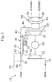
- Embodiment 2 of the present invention a humidifier/cooler (41) and a water introducing section (42) are provided in addition to the construction of Embodiment 1 described above.
- Other structures are the same as in Embodiment 1.
- the humidifier/cooler (41) is disposed partway in the second inlet duct (43) , i.e., in a portion of the second channel (40) upstream of the heat exchanger (30).
- the humidifier/cooler (41) is provided with a permeable membrane capable of permeating moisture, and divided into air side and water side spaces by the permeable membrane.
- the air side space is communicated with the second inlet duct (43) so that the secondary air flows therethrough.
- the water side space is communicated with a water pipe (50) so that city water or the like is supplied thereto.
- the humidifier/cooler (41) constitutes a moisture supplying means (41) for humidifying and cooling the secondary air to be supplied to the heat exchanger (30) .
- the water introducing section (42) is disposed in the heat absorption side passage (32) of the heat exchanger (30) .
- the water introducing section (42) is provided with a permeable membrane capable of permeating moisture, wherein a water side space is formed on one side of the permeable membrane and the side of the permeable membrane opposite to the water side space constitutes the heat absorption side passage (32) of the heat exchanger (30) .
- the water side space is communicated with the water pipe (50) so that city water or the like is supplied thereto.
- moisture in the water side space is supplied to the secondary air in the heat absorption side passage (32) by the permeation through the permeable membrane.
- the water introducing section (42) supplies moisture to the secondary air in the heat absorption side passage (32) . Accordingly, in the heat absorption side passage (32) , the secondary air is heated up through heat exchange with the primary air and at the same time the moisture in the secondary air is evaporated. This suppresses temperature rise of the secondary air and ensures the temperature differential of the secondary air from the primary air.
- the water introducing section (42) constitutes a moisture supplying means (42) for supplying moisture to the secondary air in order to use latent heat of evaporation to cool the primary air.
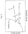
- an outside air in a state of point A is taken as a primary air through the first inlet duct (23) .
- This primary air is dehumidified through contact with the rotor member (61) in the moisture absorbing section (62) of the dehumidifying mechanism (60) to reduce its absolute humidity and increase its temperature, so that it changes from the state of point A to a state of point B along an isenthalpic line.
- the primary air in the state of point B is compressed by the compressor (21) to increase its temperature and pressure while maintaining a constant absolute humidity, so that it comes to a state of point C.
- the primary air in the state of point C enters the heat exchanger (30) to flow into the heat release side passage (31) and exchange heat with the secondary air in the heat absorption side passage (32) .
- the primary air is cooled through this heat exchange to reduce its temperature while maintaining the constant absolute humidity, so that it comes to a state of point D.
- the primary air in the state of point D is expanded by the expander (22) to reduce its temperature and pressure while maintaining the constant absolute humidity, so that it comes to a state of point E. Then, the primary air in the state of point E is supplied to a room through the first outlet duct ( 24 ).
- a room air in a state of point F is taken as the secondary air through the second inlet duct (43).
- This secondary air enters the humidifier/cooler (41) so that it is supplied with moisture, and the supplied moisture is evaporated in the secondary air.
- the secondary air thereby increases its absolute humidity and reduces its temperature, so that it changes from the state of point F to a state of point G along an isenthalpic line.
- the secondary air in the state of point G enters the heat exchanger (30) to flow into the heat absorption side passage (32) and exchanges heat with the primary air in the heat release side passage (31) .
- the secondary air thereby increases its absolute humidity and temperature so that it changes from the state of point G to a state of point H.
- the secondary air in the state of point H enters the moisture releasing section (63) of the dehumidifying mechanism (60) through the second outlet duct (44) .
- the secondary air contacts the rotor member (61) so that the rotor member (61) releases moisture to the secondary air.
- the secondary air thereby increases its absolute humidity and reduces its temperature so that it changes to the state of point H to a state of point I along an isenthalpic line.
- the secondary air in the state of point I is discharged to outdoors through the second outlet duct (44) again.
- the rotor member (61) In the dehumidifying mechanism (60) , the rotor member (61) is driven into rotation. This rotor member (61) thereby moves between the moisture absorbing section (62) and the moisture releasing section (63) to repeat moisture absorption in the moisture absorbing section (62) and moisture release in the moisture releasing section (63) . This provides continuous dehumidification of the primary air.
- Embodiment 2 the following effects can be obtained in addition to the effects of Embodiment 1.
- the humidifier/cooler (41) is provided to supply moisture to the secondary air, and the secondary air is cooled therein and then supplied to the heat exchanger (30) .
- the water introducing section (42) is provided to supply moisture to the secondary air in the heat absorption side passage (32) , and latent heat of evaporation of the moisture is used to cool the primary air in the heat exchanger (30) . Therefore, the primary air can be cooled to a still lower temperature in the heat exchanger (30) than in the case of Embodiment 1. This makes it possible to drop the air temperature at the inlet of the expander (22) to a lower degree. As a result, this embodiment enables further reduction in the input to the compressor (21) while maintaining the refrigerating capacity and thereby provides improved COP (coefficient of performance) with higher reliability.
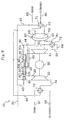
- Embodiment 3 of the present invention a preheater (33) is provided in addition to the construction of Embodiment 2 described above, and the heat exchanger (30) in Embodiment 2 is composed of a first heat exchange section (30a) and a second heat exchange section (30b) .
- Other structures are the same as in Embodiment 2.
- the first heat exchange section (30a) and the second heat exchange section (30b) of the heat exchanger (30) are each provided with a heat release side passage (31) and a heat absorption side passage (32).
- the heat release side passage (31) at the side of the first heat exchange section (30a ) is connected to the compressor (21)
- the heat release side passage (31) at the side of the second heat exchange section (30b) is connected to the expander (22) .
- the heat absorption side passage (32) at the side of the second heat exchange section (30b) is connected to the second inlet duct (43)
- the heat absorption side passage (32) at the side of the first heat exchange section (30a) is connected to the second outlet duct (44) .
- the preheater (33) is disposed between the first heat exchange section (30a) and the second heat exchange section (30b) and connected to the heat release side passages (31) of both the heat exchange sections (30a, 30b) . Further, both ends of the preheater (33) are connected to the first inlet duct (23) leading from the dehumidifying mechanism ( 60 ) to the compressor (21) . The preheater (33) thereby heats the primary air, which is being supplied to the compressor (21) following dehumidification in the dehumidifying mechanism (60) , through heat exchange with the primary air having reached a high temperature as a result of compression in the compressor (21) .
- a cooling operation is effected substantially in the same behavior as in Embodiment 2.
- the dehumidified primary air is supplied to the compressor (21) following the passage through the preheater (33).
- the primary air is dehumidified in the moisture absorbing section (62) of the dehumidifying mechanism (60) and then enters the preheater (33) through the first inlet duct (23) .
- the primary air having entered through the first inlet duct (23) is heated up through heat exchange with the primary air having been compressed by the compressor (21) .
- the heated primary air flows through the first inlet duct (23) again and is then supplied to the compressor (21) .
- the dehumidified primary air is preheated in the preheater (33) and then enters the compressor (21) . Accordingly, in this embodiment, the temperature of the primary air at the inlet of the compressor (21) becomes higher than that in the state of point B of Figure 3, and the temperature of the primary air at the outlet of the compressor (21) correspondingly becomes higher than that in the state of point C of Figure 3 .
- the temperature of the primary air at the inlet of the heat exchanger (30) becomes higher than that in Embodiment 2. Accordingly, the secondary air is heat exchanged with the primary air of higher temperature in the heat exchanger (30) so that the temperature of the secondary air at the outlet of the heat exchanger (30) becomes higher than that in the state of point H of Figure 3. Further, since the temperature of the primary air at the inlet of the heat exchanger (30) is elevated, the temperature differential equivalent to that in Embodiment 2 can be ensured even if the temperature of the secondary air is high in the heat absorption side passage (32) .
- the amount of moisture supplied to the secondary air in the humidifier/cooler (41) and the water introducing section (42) is reduced so that the absolute humidity of the secondary air at the outlet of the heat exchanger (30) becomes lower than that in the state of point H of Figure 3 .
- the secondary air having exited from the heat exchanger (30) enters the moisture releasing section (63) of the dehumidifying mechanism (60) through the second outlet duct (44) , and the rotor member (61) releases moisture therein to the secondary air.
- the primary air at the inlet of the heat exchanger (30) becomes higher than that in Embodiment 2.
- this primary air is heat exchanged not only with the primary air in the first heat exchange section (30a) and the second heat exchange section (30b) of the heat exchanger (30) but also with a yet-to-be compressed primary air in the preheater (33) .
- the temperature of the primary air at the outlet of the heat exchanger (30) i.e., at the inlet of the expander (22) , becomes equal to that in Embodiment 2, which ensures the cooling capacity equivalently to Embodiment 2.
- Embodiment 3 the following effects can be obtained in addition to the effects of Embodiment 2.
- the temperature of the primary air at the inlet of the compressor (21) can be elevated as compared with Embodiment 2. Further, the temperature of the secondary air at the outlet of the heat exchanger (30) can be accordingly elevated. Even with the same absolute humidity, rise in temperature of the air leads to drop in relative humidity thereof. Further, in this embodiment, since the amount of moisture supplied to the secondary air in the humidifier/cooler (41) and the water introducing section (42) can be reduced, the absolute humidity of the secondary air at the outlet of the heat exchanger (30) can be lowered. Accordingly, in this embodiment, the rotor member (61) will release moisture to the secondary air higher in temperature and lower in relative humidity than that in Embodiment 2. This makes it possible to regenerate the solid adsorbent of the rotor member (61) with higher reliability.
- the preheater (33) may be disposed in the following manner.
- both ends of the preheater (33) are connected to the first inlet duct (23) leading from the dehumidifying mechanism (60) to the compressor (21) .
- the primary air compressed by the compressor (21) is distributed so that part thereof is conducted to the preheater (33) and the remaining part is supplied to the heat exchanger (30) .
- the yet-to-be compressed primary air is heated up through heat exchange with the part of the compressed primary air.
- the primary air heated up in the preheater (33) is supplied to the compressor (21) .
- the compressed primary air having exited from the preheater (33) is conducted to the heat release side passages (31) of the heat exchanger (30) , and then combined with the primary air having entered the heat exchanger (30) directly from the compressor (21) .
- the air conditioning system (10) of Embodiment 4 is arranged to provide heating for a room.
- this air conditioning system (10) is configured substantially in the same manner as Embodiment 1, but is different from that in the following points. Specifically, in the first channel (20) , the first inlet duct (23) is opened at its one end to the room to take in a room air as a primary air. Further, the first outlet duct (24) is opened at its one end to outdoors to discharge outdoors the low-temperature primary air coming from the expander (22) . On the other hand, in the second channel (40) , the second inlet duct (43) is opened at its one end to outdoors to take in an outside air as a secondary air. Further, the second outlet duct (44) is opened at its one end to the room to supply the high-temperature secondary air coming from the heat exchanger (30) to the room. Other structures are the same as in Embodiment 1.
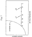
- a room air in a state of point J is taken as a primary air through the first inlet duct (23) .
- This primary air is dehumidified through contact with the rotor member (61) in the moisture absorbing section (62) of the dehumidifying mechanism (60) to reduce its absolute humidity and increase its temperature, so that it changes from the state of point J to a state of point K along an isenthalpic line.
- the primary air in the state of point K is compressed by the compressor (21) to increase its temperature and pressure while maintaining a constant absolute humidity, so that it comes to a state of point L.
- the primary air in the state of point L enters the heat exchanger (30) to flow into the heat release side passage (31) and exchanges heat with a secondary air in the heat absorption side passage (32) .
- the primary air is cooled through this heat exchange to reduce its temperature while maintaining the constant absolute humidity, so that it comes to a state of point M.
- the primary air in the state of point M is expanded by the expander (22) to reduce its temperature and pressure while maintaining the constant absolute humidity, so that it comes to a state of point N. Then, the primary air in the state of point N is discharged to outdoors through the first outlet duct (24).
- an outside air in a state of point O is taken as the secondary air through the second inlet duct (43).
- the secondary air in the state of point O enters the heat exchanger (30) to flow into the heat absorption side passage (32) and exchanges heat with the primary air in the heat release side passage (31).
- the secondary air thereby increases its temperature while maintaining the constant absolute humidity so that it changes from the state of point O to a state of point P.
- the secondary air in the state of point P enters the moisture releasing section (63) of the dehumidifying mechanism (60) through the second outlet duct (44) . In the moisture releasing section (63) , the secondary air contacts the rotor member (61) so that the rotor member (61) releases moisture to the secondary air.
- the secondary air is humidified in the moisture releasing section (63) .
- the secondary air thereby increases its absolute humidity and reduces its temperature so that it changes to the state of point P to a state of point Q along a isenthalpic line.
- the secondary air in the state of point Q is supplied to the room through the second outlet duct (44) again.
- the rotor member (61) In the dehumidifying mechanism (60) , the rotor member (61) is driven into rotation. This rotor member (61) thereby moves between the moisture absorbing section (62) and the moisture releasing section (63) to repeat moisture absorption in the moisture absorbing section (62) and moisture release in the moisture releasing section (63). This provides continuous dehumidification of the primary air and continuous humidification of the secondary air.
- Embodiment 4 dehumidification of the primary air is effected by the rotor member (61) having the solid adsorbent like Embodiment 1. Therefore, according to this embodiment, the effects of improving design flexibility and simplifying the construction can be obtained like Embodiment 1.
- the secondary air of an outside air cools the compressed primary air. Therefore, hot heat can be recovered from the room air being discharged to outdoors for ventilation.
- the moisture releasing section (63) of the dehumidifying mechanism (60) the rotor member (61) releases moisture to the secondary air.
- the secondary air to be supplied to the room can be humidified by the moisture removed from the primary air of a room air. Therefore, the moisture contained in the room air to be discharged to outdoors can be recovered. As a result, energy of the room air being discharged can be recovered inclusive of energy of the moisture in the room air, which further reduces energy loss involved in ventilation.
- Embodiment 5 of the present invention is arranged to accomplish both cooling and heating operations by providing a first four-way selector valve (71) and a second four-way selector valve (72) each as a selector means in addition to the construction of Embodiment 2 described above.
- the following description will be made about structures different from Embodiment 2.
- the first inlet duct (23) of the first channel (20) is connected at its one end to the first four-way selector valve (71) .
- the second inlet duct (43) of the second channel (40) is also connected at its one end to the first four-way selector valve (71) .
- the first four-way selector valve (71) is connected to a room air duct (85) and an outside air duct (86).
- the room air duct (85) is opened at its one end to a room to take in a room air.
- the outside air duct (86) is opened at its one end to outdoors to take in an outside air.
- the first outlet duct (24) of the first channel (20) is connected at its one end to the second four-way selector valve (72) .
- the second outlet duct (44) of the second channel (40) is also connected at its one end to the second four-way selector valve (72) .
- the second four-way selector valve (72) is connected to a supply duct (87) and a discharge duct (88).
- the supply duct (87) is opened at its one end to the room to supply air thereto.
- the discharge duct (88) is opened at its one end to outdoors to discharge air thereto.
- the first four-way selector valve (71) and the second four-way selector valve (72) are switched to the positions as indicated in solid lines in Figure 8 .
- the outside air duct (86) is communicated with the first inlet duct (23)
- the room air duct (85) is communicated with the second inlet duct (43)
- the first outlet duct (24) is communicated with the supply duct (87)
- the second outlet duct (44) is communicated with the discharge duct (88).
- the system operates in the same manner as in Embodiment 2 thereby effecting the cooling operation.
- the first inlet duct (23) takes in an outside air as the primary air through the outside air duct (86).
- This primary air sequentially flows through the dehumidifying mechanism (60) , the compressor (21), the heat exchanger (30) and the expander (22) and is supplied to the room through the first outlet duct (24) and the supply duct (87) .
- the second inlet duct (43) takes in a room air as the secondary air through the room air duct (85) .
- This secondary air sequentially flows through the humidifier/cooler (41) , the heat exchanger (30) and the dehumidifying mechanism (60) , and is discharged to outdoors through the second outlet duct (44) and the discharge duct (88) .
- the first four-way selector valve (71) and the second four-way selector valve (72) are switched to the positions as indicated in dash lines in Figure 8.
- the outside air duct (86) is communicated with the second inlet duct (43), while the room air duct (85) is communicated with the first inlet duct (23).
- the second outlet duct (44) is communicated with the supply duct (87), while the first outlet duct (24) is communicated with the discharge duct (88).
- the first inlet duct (23) takes in a room air as the primary air through the room air duct (85) .
- This primary air sequentially flows through the dehumidifying mechanism (60) , the compressor (21) , the heat exchanger (30) and the expander (22) , and is discharged to outdoors through the first outlet duct (24) and the discharge duct (88) .
- the second inlet duct (43) takes in an outside air as the secondary air through the outside air duct (86) .
- This secondary air sequentially flows through the humidifier/cooler (41), the heat exchanger (30) and the dehumidifying mechanism (60) , and is supplied to the room through the second outlet duct (44) and the supply duct (87) .
- Embodiment 6 of the present invention is arranged to accomplish both cooling and heating operations by providing a first four-way selector valve (71) and a second four-way selector valve (72) each as a selector means and a third four-way selector valve (73) as a bypassing means in addition to the construction of Embodiment 3 described above.
- the first four-way selector valve (71) is connected to the room air duct (85) , the outside air duct (86) , the first inlet duct (23) and the second inlet duct (43) like Embodiment 5, and the room air duct (85) and the outside air duct (86) are structured likewise.
- the second four-way selector valve (72) is likewise connected to the supply duct (87) , the discharge duct (88) , the first outlet duct (24) and the second outlet duct (44) , and the structures of the supply duct (87) and the discharge duct (88) are the same as in Embodiment 5.
- a portion of the first inlet duct (23) located between the dehumidifying mechanism (60) and the compressor (21) consists of first to fourth subportions (81, 82, 83, 84).
- the first sub-portion (81) is connected at its one end to the moisture absorbing section (62) of the dehumidifying mechanism (60) and connected at the other end to the third four-way selector valve (73).
- the second sub-portion (82) is connected at its one end to the third four-way selector valve (73) and connected at the other end to the inlet side of the preheater (33).
- the third sub-portion (83) is connected at its one end to the outlet side of the preheater (33) and connected at the other end to the third four-way selector valve (73) .
- the fourth sub-portion (84) is connected at its one end to the third four-way selector valve (73) and connected at the other end to the compressor (21).
- the first to third four-way selector valves (71, 72, 73) are switched to the positions as indicated in solid lines in Figure 9 .
- the first four-way selector valve (71) and the second four-way selector valve (72) are put into the same conditions as in Embodiment 5.
- the third four-way selector valve (73) communicates the first sub-portion (81) with the second sub-portion (82) and communicates the third sub-portion (83) with the fourth sub-portion (84). In these conditions, the system operates in the same manner as in Embodiment 3 thereby effecting the cooling operation.
- the first inlet duct (23) takes in an outside air as the primary air through the outside air duct (86) .
- This primary air passes through the dehumidifying mechanism (60) , the first sub-portion (81) and the second sub-portion (82) , enters the preheater (33) , is heated therein, and is then supplied through the third sub-portion (83) and the fourth sub-portion (84) to the compressor (21) .
- the primary air sequentially flows through the first heat exchange section (30a) , the preheater (33) , the second heat exchange section (30b) and the expander (22) and is supplied to the room through the first outlet duct (24) and the supply duct (87).
- the second inlet duct (43) takes in a room air as the secondary air through the room air duct (85) .
- This secondary air sequentially flows through the humidifier/cooler (41) , the second heat exchange section (30b) and the dehumidifying mechanism (60) and is discharged to outdoors through the second outlet duct (44) and the discharge duct (88).
- the first to third four-way selector valves (71, 72, 73) are switched to the positions as indicated in dash lines in Figure 9 .
- the first four-way selector valve (71) and the second four-way selector valve (72) are put into the same conditions as in Embodiment 5.
- the third four-way selector valve (73) communicates the first sub-portion (81) with the fourth sub-portion (84) . Accordingly, the primary air having exited from the dehumidifying mechanism (60) bypasses the preheater (33) and is supplied directly to the compressor (21). Further, no moisture is supplied from the humidifier/cooler (41) and the water introducing section (42) to the secondary air. Therefore, in this embodiment, the system operates in the same manner as in Embodiment 4 thereby effecting the heating operation.
- the first inlet duct (23) takes in a room air as the primary air through the room air duct (85) .
- This primary air sequentially flows through the dehumidifying mechanism (60), the third four-way selector valve (73), the compressor (21), the heat exchanger (30) and the expander (22) and is discharged to outdoors through the first outlet duct (24) and the discharge duct (88).
- the second inlet duct (43) takes in an outside air as the secondary air through the outside air duct (86) .
- This secondary air sequentially flows through the humidifier/cooler (41), the heat exchanger (30) and the dehumidifying mechanism (60) , and is then supplied to the room through the second outlet duct (44) and the supply duct (87).
- this modified example is also arranged to accomplish both cooling and heating operations by providing a first four-way selector valve (71) and a second four-way selector valve (72) each as a selector means and a third four-way selector valve (73) as a bypassing means in addition to the construction of the modified example of Embodiment 3 described above.
- an on-off valve (74) is provided in a path which leads part of the primary air coming from the compressor (21) to the preheater (33) .
- the on-off valve (74) is opened during the cooling operation to lead part of the primary air to the preheater (33) , while it is closed during the heating operation to lead all of the primary air coming from the compressor (21) to the heat exchanger (30).
- the dehumidifying mechanism (60) is formed by using the solid adsorbent.
- the dehumidifying mechanism (60) may be formed by using a liquid absorbent instead.
- the dehumidifying mechanism (60) using the liquid absorbent will be described by taking the case of applying it to Embodiment 1 as an example.
- the dehumidifying mechanism (60) of this modification consists of a circulation circuit (64) formed by sequentially connecting a moisture absorbing section (65) , a moisture releasing section (66) and a pump (67) through liquid piping (68) .
- the circulation circuit (64) is filled with a water solution of metallic halide as a liquid absorbent.
- metallic halide of this kind include LiCl, LiBr and CaCl 2 .
- the liquid absorbent may be a water solution of hydrophilic organic compound. Examples of organic compound of this kind include ethylene glycol, glycerin and hydrophilic resin.
- the moisture absorbing section (65) is placed partway in the first inlet duct (23) .
- the moisture absorbing section (65) is provided with a hydrophobic porous membrane capable of permeating moisture, and divided into air side and liquid side spaces by the hydrophobic porous membrane.
- the air side space is communicated with the first inlet duct (23) so that the primary air flows therethrough.
- the liquid side space is communicated with the liquid piping (68) so that the liquid absorbent flows therethrough.
- the primary air in the air side space indirectly contacts the liquid absorbent in the liquid side space through the hydrophobic porous membrane so that moisture contained in the primary air is absorbed in the liquid absorbent after the permeation through the hydrophobic porous membrane. In this manner, the moisture absorbing section (65) effects dehumidification of the primary air.
- the moisture releasing section (66) is disposed in the heat exchanger (30) .
- the moisture releasing section (66) is provided with a hydrophobic porous membrane capable of permeating moisture, wherein a liquid side space is formed on one side of the hydrophobic porous membrane and the side of the hydrophobic porous membrane opposite to the liquid side space constitutes the heat absorption side passage (32) of the heat exchanger (30).
- the liquid side space is communicated with the liquid piping (68) so that the liquid absorbent flows therethrough.
- the liquid absorbent in the liquid side space is heated up through heat exchange with the secondary air in the heat absorption side passage (32) , and at the same time the liquid absorbent in the liquid side space indirectly contacts the secondary air in the heat absorption side passage (32) through the hydrophobic porous membrane so that moisture contained in the liquid absorbent is supplied to the secondary air by the permeation through the hydrophobic porous membrane. In this manner, in the moisture releasing section (66) , the liquid absorbent releases moisture to the secondary air.
- the liquid absorbent circulates by means of the pump (67) so that dehumidification of the primary air is continuously made. Specifically, the liquid absorbent absorbs moisture of the primary air in the moisture absorbing section (65) , and flows through the liquid piping (68) into the moisture releasing section (66) . In the moisture releasing section (66) , the liquid absorbent is heated up and releases moisture to the secondary air. The liquid absorbent is thereby regenerated. The regenerated liquid absorbent flows through the liquid piping (68) into the moisture absorbing section (65) . The liquid absorbent repeats this circulation.
- a cooling operation is effected by taking an outside air as the primary air into the first channel (20) while taking a room air as the secondary air into the second channel (40) .
- a cooling operation may be effected in the following manners.
- An outside air may be first taken in as the primary air through the first inlet duct (23) of the first channel (20) and supplied to a room through the first outlet duct (24) , while another outside air may be taken in as the secondary air through the second inlet duct (43) of the second channel (40) and discharged to outdoors through the second outlet duct (44).
- a room air may be taken in as the primary air through the first inlet duct (23) of the first channel (20) and supplied to a room through the first outlet duct (24)
- another room air may be taken in as the secondary air through the second inlet duct (43) of the second channel (40) and discharged to outdoors through the second outlet duct (44) .
- a room air may be taken in as the primary air through the first inlet duct (23) of the first channel (20) and supplied to a room through the first outlet duct (24)
- an outside air may be taken in as the secondary air through the second inlet duct (43) of the second channel (40) and discharged to outdoors through the second outlet duct (44) .
- a mixed air of room and outside airs may be taken in as the primary air through the first inlet duct (23) of the first channel (20) and supplied to a room through the first outlet duct (24) , while a room air may be taken in as the secondary air through the second inlet duct (43) of the second channel (40) and discharged to outdoors through the second outlet duct (44) .
- a mixed air of room and outside airs may be taken in as the primary air through the first inlet duct (23) of the first channel (20) and supplied to a room through the first outlet duct (24) , while an outside air may be taken in as the secondary air through the second inlet duct (43) of the second channel (40) and discharged to outdoors through the second outlet duct (44).
- a mixed air of room and outside airs may be taken in as the primary air through the first inlet duct (23) of the first channel (20) and supplied to a room through the first outlet duct (24)
- another mixed air of room and outside airs may be taken in as the secondary air through the second inlet duct (43) of the second channel (40) and discharged to outdoors through the second outlet duct (44).
- a heating operation is effected by taking a room air as the primary air into the first channel (20) while taking an outside air as the secondary air into the second channel (40).
- a heating operation may be effected in the following manners.
- An outside air may be first taken in as the primary air through the first inlet duct (23) of the first channel (20) and discharged to outdoors through the first outlet duct (24), while another outside air may be taken in as the secondary air through the second inlet duct (43) of the second channel (40) and supplied to a room through the second outlet duct (44).
- a room air may be taken in as the primary air through the first inlet duct (23) of the first channel (20) and discharged to outdoors through the first outlet duct (24)
- another room air may be taken in as the secondary air through the second inlet duct (43) of the second channel (40) and supplied to a room through the second outlet duct (44) .
- an outside air may be taken in as the primary air through the first inlet duct (23) of the first channel (20) and discharged to outdoors through the first outlet duct (24)
- a room air may be taken in as the secondary air through the second inlet duct (43) of the second channel (40) and supplied to a room through the second outlet duct (44) .
- a room air may be taken in as the primary air through the first inlet duct (23) of the first channel (20) and discharged to outdoors through the first outlet duct (24)
- a mixed air of room and outside airs may be taken in as the secondary air through the second inlet duct (43) of the second channel (40) and supplied to a room through the second outlet duct (44) .
- an outside air may be taken in as the primary air through the first inlet duct (23) of the first channel (20) and discharged to outdoors through the first outlet duct (24)
- a mixed air of room and outside airs may be taken in as the secondary air through the second inlet duct (43) of the second channel (40) and supplied to a room through the second outlet duct (44).
- a mixed air of room and outside airs may be taken in as the primary air through the first inlet duct (23) of the first channel (20) and discharged to outdoors through the first outlet duct (24)
- another mixed air of room and outside airs may be taken in as the secondary air through the second inlet duct (43) of the second channel (40) and supplied to a room through the second outlet duct (44) .
- the air conditioning system according to the present invention is useful for cooling or heating a room, and particularly suitable for providing air conditioning in an air cycle.
Landscapes
- Engineering & Computer Science (AREA)
- Combustion & Propulsion (AREA)
- Chemical & Material Sciences (AREA)
- Mechanical Engineering (AREA)
- General Engineering & Computer Science (AREA)
- Pulmonology (AREA)
- General Health & Medical Sciences (AREA)
- Aviation & Aerospace Engineering (AREA)
- Health & Medical Sciences (AREA)
- Life Sciences & Earth Sciences (AREA)
- Sustainable Development (AREA)
- Central Air Conditioning (AREA)
- Drying Of Gases (AREA)
Abstract
Description
Claims (35)
- An air conditioning system for effecting air conditioning in an air cycle comprising a compressor (21), a heat exchanger (30) and an expander (22), said air conditioning system comprisingdehumidifying means (60) that includes a humidity medium for absorbing and releasing moisture through contact with an air and allows the humidity medium to absorb moisture in a primary air to be supplied to the compressor (21) while releasing the moisture therein to a secondary air thereby continuously dehumidifying the primary air.
- The air conditioning system of claim 1, whereinthe heat exchanger (30) is arranged to cool the compressed primary air through heat exchange with the secondary air, andthe dehumidifying means (60) is arranged to release moisture in the humidity medium to the secondary air coming from the heat exchanger (30).
- The air conditioning system of Claim 1 or 2, wherein the humidity medium of the dehumidifying means (60) comprises a solid adsorbent for adsorbing moisture.
- The air conditioning system of Claim 3, whereinthe humidity medium of the dehumidifying means (60) is formed of a rotor member (61) that is formed in the shape of a disc to allow air passage in a direction of its thickness and provides contact of the passing air with the solid adsorbent, andthe dehumidifying means (60) comprises a moisture absorbing section (62) where the rotor member (61) absorbs moisture in the primary air through contact with the primary air, a moisture releasing section (63) where the rotor member (61) releases moisture therein to the secondary air through contact with the secondary air, and a drive mechanism for rotatively driving the rotor member (61) to allow the rotor member (61) to move between the moisture absorbing section (62) and the moisture releasing section (63).
- The air conditioning system of Claim 3, wherein the solid adsorbent is made of porous inorganic oxide.
- The air conditioning system of Claim 1 or 2, wherein the humidity medium of the dehumidifying means (60) comprises a liquid absorbent for absorbing moisture.
- The air conditioning system of Claim 1, whereinthe humidity medium of the dehumidifying means (60) comprises a liquid absorbent for absorbing moisture, andthe dehumidifying means (60) is arranged so that the liquid absorbent is heated by the primary air coming from the compressor (21) to release moisture having absorbed from the primary air to the secondary air.
- The air conditioning system of Claim 6 or 7, wherein the dehumidifying means (60) includes a moisture-permeable, hydrophobic porous membrane and is arranged to contact the liquid absorbent with the primary air through the hydrophobic porous membrane.
- The air conditioning system of Claim 6 or 7, wherein the liquid absorbent is made of a water solution of hydrophilic organic compound.
- The air conditioning system of Claim 6 or 7, wherein the liquid absorbent is made of a water solution of metallic halide.
- The air conditioning system of Claim 6 or 7, wherein the dehumidifying means (60) comprises a circulation circuit (64) that includes a moisture absorbing section (65) for contacting the liquid absorbent with the primary air and a moisture releasing section (66) for contacting the liquid absorbent with the secondary air and circulates the liquid absorbent between the moisture absorbing section (65) and the moisture releasing section (66).
- The air conditioning system of Claim 2, wherein cooling of a room is effected by supplying the primary air expanded in the expander (22) to the room.
- The air conditioning system of Claim 12, whereinthe primary air is an outside air taken from outdoors and then supplied to the room through the expander (22), whilethe secondary air is a room air taken from the room and then discharged to outdoors through the dehumidifying means (60).
- The air conditioning system of Claim 12, whereinthe primary air is an outside air taken from outdoors and then supplied to the room through the expander (22), whilethe secondary air is an outside air taken from outdoors and then discharged to outdoors through the dehumidifying means (60).
- The air conditioning system of Claim 12, whereinthe primary air is a room air taken from the room and then supplied to the room through the expander (22), whilethe secondary air is a room air taken from the room and then discharged to outdoors through the dehumidifying means (60).
- The air conditioning system of Claim 12, whereinthe primary air is a room air taken from the room and then supplied to the room through the expander (22), whilethe secondary air is an outside air taken from outdoors and then discharged to outdoors through the dehumidifying means (60).
- The air conditioning system of Claim 12, whereinthe primary air is a mixed air of a room air taken from the room and an outside air taken from outdoors and is supplied to the room through the expander (22), whilethe secondary air is a room air taken from the room and then discharged to outdoors through the dehumidifying means (60).
- The air conditioning system of Claim 12, whereinthe primary air is a mixed air of a room air taken from the room and an outside air taken from outdoors and is supplied to the room through the expander (22), whilethe secondary air is an outside air taken from outdoors and then discharged to outdoors through the dehumidifying means (60).
- The air conditioning system of Claim 12, whereinthe primary air is a mixed air of a room air taken from the room and an outside air taken from outdoors and is supplied to the room through the expander (22), whilethe secondary air is a mixed air of a room air taken from the room and an outside air taken from outdoors and is discharged to outdoors through the dehumidifying means (60).
- The air conditioning system of Claim 12, comprising preheating means (33) for heating the primary air dehumidified by the dehumidifying means (60) through heat exchange with the primary air compressed by the compressor (21) and then supplying the primary air to the compressor (21).
- The air conditioning system of Claim 12, comprising preheating means (33) for heating the primary air dehumidified by the dehumidifying means (60) through heat exchange with part of the primary air compressed by the compressor (21) and then supplying the primary air to the compressor (21).
- The air conditioning system of Claim 12, comprising moisture supplying means (41) for supplying moisture to the secondary air not yet supplied to the heat exchanger (30) in order to humidify and cool the secondary air.
- The air conditioning system of Claim 12, comprising moisture supplying means (42) for supplying moisture to the secondary air in the heat exchanger (30) in order to use latent heat of evaporation of water to cool the primary air in the heat exchanger (30).
- The air conditioning system of Claim 22 or 23, wherein the moisture supplying means (41, 42) is arranged to supply moisture to the secondary air through a permeable membrane capable of permeating moisture.
- The air conditioning system of Claim 2, wherein heating of a room is effected by supplying the secondary air heated through heat exchange with the primary air in the heat exchanger (30) to the room.
- The air conditioning system of Claim 25, whereinthe primary air is a room air taken from the room and then discharged to outdoors through the expander (22), whilethe secondary air is an outside air taken from outdoors and then supplied to the room through the dehumidifying means (60).
- The air conditioning system of Claim 25, whereinthe primary air is an outside air taken from outdoors and then discharged to outdoors through the expander (22), whilethe secondary air is an outside air taken from outdoors and then supplied to the room through the dehumidifying means (60).
- The air conditioning system of Claim 25, whereinthe primary air is a room air taken from the room and then discharged to outdoors through the expander (22), whilethe secondary air is a room air taken from the room and then supplied to the room through the dehumidifying means (60).
- The air conditioning system of Claim 25, whereinthe primary air is an outside air taken from outdoors and then discharged to outdoors through the expander (22), whilethe secondary air is a room air taken from the room and then supplied to the room through the dehumidifying means (60).
- The air conditioning system of Claim 25, whereinthe primary air is a room air taken from the room and then discharged to outdoors through the expander (22), whilethe secondary air is a mixed air of a room air taken from the room and an outside air taken from outdoors and is supplied to the room through the dehumidifying means (60).
- The air conditioning system of Claim 25, whereinthe primary air is an outside air taken from outdoors and then discharged to outdoors through the expander (22), whilethe secondary air is a mixed air of a room air taken from the room and an outside air taken from outdoors and is supplied to the room through the dehumidifying means (60).
- The air conditioning system of Claim 25, whereinthe primary air is a mixed air of a room air taken from the room and an outside air taken from outdoors and is discharged to outdoors through the expander (22), whilethe secondary air is a mixed air of a room air taken from the room and an outside air taken from outdoors and is supplied to the room through the dehumidifying means (60).
- The air conditioning system of Claim 2, comprising selector means (71, 72) for taking in different airs as the primary and secondary airs for each of cooling and heating operations and selecting the primary air from the expander (22) and the secondary air from the dehumidifying means (60) to supply them to the room to thereby allow both the cooling and heating operations.
- The air conditioning system of Claim 33, comprisingpreheating means (33) for heating the primary air dehumidified by the dehumidifying means (60) through heat exchange with the primary air compressed by the compressor (21) and then supplying the primary air to the compressor (21), andbypassing means (73) for allowing the primary air to bypass the preheating means (33) and to be supplied directly to the compressor (21) during the heating operation.
- The air conditioning system of Claim 33, comprisingpreheating means (33) for heating the primary air dehumidified by the dehumidifying means (60) through heat exchange with part of the primary air compressed by the compressor (21) and then supplying the primary air to the compressor (21), andbypassing means (73) for allowing the primary air to bypass the preheating means (33) and to be supplied directly to the compressor (21) during the heating operation.
Applications Claiming Priority (3)
| Application Number | Priority Date | Filing Date | Title |
|---|---|---|---|
| JP11058019A JP2000257968A (en) | 1999-03-05 | 1999-03-05 | Air conditioner |
| JP5801999 | 1999-03-05 | ||
| PCT/JP2000/001210 WO2000053982A1 (en) | 1999-03-05 | 2000-03-01 | Air conditioner |
Publications (3)
| Publication Number | Publication Date |
|---|---|
| EP1164339A1 true EP1164339A1 (en) | 2001-12-19 |
| EP1164339A4 EP1164339A4 (en) | 2002-04-10 |
| EP1164339B1 EP1164339B1 (en) | 2004-06-02 |
Family
ID=13072264
Family Applications (1)
| Application Number | Title | Priority Date | Filing Date |
|---|---|---|---|
| EP00906611A Expired - Lifetime EP1164339B1 (en) | 1999-03-05 | 2000-03-01 | Air conditioner |
Country Status (7)
| Country | Link |
|---|---|
| US (1) | US6619064B1 (en) |
| EP (1) | EP1164339B1 (en) |
| JP (1) | JP2000257968A (en) |
| KR (1) | KR20010102493A (en) |
| CN (1) | CN1224816C (en) |
| DE (1) | DE60011249D1 (en) |
| WO (1) | WO2000053982A1 (en) |
Cited By (3)
| Publication number | Priority date | Publication date | Assignee | Title |
|---|---|---|---|---|
| CN104676780A (en) * | 2015-03-17 | 2015-06-03 | 殷洪生 | Central air conditioner fresh air handling unit structure and operating method thereof |
| WO2018070893A1 (en) | 2016-10-10 | 2018-04-19 | Общество с ограниченной ответственностью "ДЕТА Инжиниринг" | Supply and exhaust system |
| EP3961112A4 (en) * | 2019-04-24 | 2022-04-13 | Mitsubishi Electric Corporation | AIR CONDITIONING DEVICE |
Families Citing this family (25)
| Publication number | Priority date | Publication date | Assignee | Title |
|---|---|---|---|---|
| US6360557B1 (en) * | 2000-10-03 | 2002-03-26 | Igor Reznik | Counter flow air cycle air conditioner with negative air pressure after cooling |
| JP2002115869A (en) * | 2000-10-12 | 2002-04-19 | Daikin Ind Ltd | Humidity control device |
| KR100381373B1 (en) * | 2000-11-09 | 2003-04-26 | 한국가스공사연구개발원 | Absorbent solution composition for use with absorption refrigeration and heating apparatus |
| JP3709815B2 (en) | 2001-07-18 | 2005-10-26 | ダイキン工業株式会社 | Air conditioner |
| JP2003097825A (en) | 2001-07-18 | 2003-04-03 | Daikin Ind Ltd | Air conditioner |
| JP3695417B2 (en) | 2002-02-04 | 2005-09-14 | ダイキン工業株式会社 | Humidity control device |
| KR100928980B1 (en) * | 2002-12-23 | 2009-11-26 | 주식회사 포스코 | Cooling device of hot-dip galvanized steel sheet with improved cooling capacity |
| JP3668786B2 (en) * | 2003-12-04 | 2005-07-06 | ダイキン工業株式会社 | Air conditioner |
| WO2005057087A1 (en) * | 2003-12-09 | 2005-06-23 | Earthship K.K. | Air conditioning system |
| US20060168974A1 (en) * | 2005-01-31 | 2006-08-03 | Fernandes John P | Self contained humidity control system for forced air duct system |
| KR101207298B1 (en) * | 2006-02-13 | 2012-12-03 | 한라공조주식회사 | air compressor and expander |
| KR100816919B1 (en) * | 2006-08-14 | 2008-03-27 | 엘지전자 주식회사 | Electrothermal ventilation system |
| CN101747948B (en) * | 2008-12-05 | 2014-07-02 | 山东恒能环保能源设备有限公司 | Treatment process for dehumidifying combustible gases in expansion way |
| US8685145B2 (en) | 2010-11-12 | 2014-04-01 | The Texas A&M University System | System and method for efficient multi-stage air dehumidification and liquid recovery |
| US8685144B2 (en) | 2010-11-12 | 2014-04-01 | The Texas A&M University System | System and method for efficient air dehumidification and liquid recovery |
| US8500848B2 (en) | 2010-11-12 | 2013-08-06 | The Texas A&M University System | Systems and methods for air dehumidification and cooling with membrane water vapor rejection |
| US8685142B2 (en) | 2010-11-12 | 2014-04-01 | The Texas A&M University System | System and method for efficient air dehumidification and liquid recovery with evaporative cooling |
| KR101265683B1 (en) | 2012-01-02 | 2013-05-22 | 한국에너지기술연구원 | Dehumidifier for a compressor, 1-stage compressing-absorbing type heat pump system and 2-stage compressing-absorbing type heat pump system |
| CN106440510B (en) * | 2016-02-25 | 2020-05-29 | 李华玉 | Second-class thermally-driven compression heat pump |
| CN111854295A (en) * | 2020-07-28 | 2020-10-30 | 山东天瑞重工有限公司 | Gas refrigerating system |
| CN112325504A (en) * | 2020-11-03 | 2021-02-05 | 珠海格力电器股份有限公司 | Air conditioner |
| US12061011B2 (en) | 2021-06-11 | 2024-08-13 | Copeland Lp | Climate-control system with sensible and latent cooling |
| CN118836540A (en) * | 2023-04-24 | 2024-10-25 | 青岛海尔空调器有限总公司 | Control method of air conditioner |
| CN118836498A (en) * | 2023-04-24 | 2024-10-25 | 青岛海尔空调器有限总公司 | Dehumidifying device and air conditioner comprising same |
| CN118163951B (en) * | 2024-02-27 | 2026-06-09 | 中国商用飞机有限责任公司 | Humidity control system and air treatment system for aircraft |
Family Cites Families (16)
| Publication number | Priority date | Publication date | Assignee | Title |
|---|---|---|---|---|
| US3844737A (en) * | 1970-03-31 | 1974-10-29 | Gas Dev Corp | Desiccant system for an open cycle air-conditioning system |
| FR2576399B1 (en) * | 1985-01-18 | 1989-03-31 | Abg Semca | ATMOSPHERE CONDITIONING METHOD AND AIR CONDITIONER IMPLEMENTING THE METHOD |
| JPS62223573A (en) * | 1986-03-25 | 1987-10-01 | 松下電工株式会社 | Air cycle heat pump |
| JPH0743151B2 (en) * | 1989-01-13 | 1995-05-15 | ダイキン工業株式会社 | Dehumidifier / humidifier and air conditioner equipped with dehumidifier / humidifier |
| JP2695665B2 (en) * | 1989-08-22 | 1998-01-14 | 日本酸素株式会社 | Low temperature air production method |
| JPH05305215A (en) * | 1992-04-30 | 1993-11-19 | Mitsubishi Heavy Ind Ltd | Absorption type dehumidifier |
| DE4235217C2 (en) * | 1992-10-14 | 1994-12-01 | Hagenuk Fahrzeugklima Gmbh | Process for heating or cooling a room |
| US5323624A (en) | 1992-11-13 | 1994-06-28 | United Technologies Corporation | Filtered environmental control system |
| US5512083A (en) * | 1993-10-25 | 1996-04-30 | Uop | Process and apparatus for dehumidification and VOC odor remediation |
| JPH08178350A (en) * | 1994-12-28 | 1996-07-12 | Matsushita Electric Ind Co Ltd | Humidity control device and air conditioner with humidity control function |
| NL9500130A (en) * | 1995-01-24 | 1996-09-02 | Tno | Regenerative heat exchanger; heat pump and cooling device with regenerative heat exchanger; heat exchange method; cooling method; method of heating. |
| SE508282C2 (en) * | 1995-02-20 | 1998-09-21 | Svenska Rotor Maskiner Ab | Cooling system for air and ways to operate such a system |
| US5555745A (en) * | 1995-04-05 | 1996-09-17 | Rotoflow Corporation | Refrigeration system |
| JPH08318731A (en) * | 1995-05-25 | 1996-12-03 | Komatsu Ltd | Air conditioning system for vehicles with supercharged engine |
| US5826434A (en) | 1995-11-09 | 1998-10-27 | Novelaire Technologies, L.L.C. | High efficiency outdoor air conditioning system |
| US5702508A (en) * | 1996-01-25 | 1997-12-30 | Moratalla; Jose | Ceramic desiccant device |
-
1999
- 1999-03-05 JP JP11058019A patent/JP2000257968A/en active Pending
-
2000
- 2000-03-01 EP EP00906611A patent/EP1164339B1/en not_active Expired - Lifetime
- 2000-03-01 US US09/914,769 patent/US6619064B1/en not_active Expired - Fee Related
- 2000-03-01 DE DE60011249T patent/DE60011249D1/en not_active Expired - Lifetime
- 2000-03-01 KR KR1020017011247A patent/KR20010102493A/en not_active Ceased
- 2000-03-01 CN CNB008070180A patent/CN1224816C/en not_active Expired - Fee Related
- 2000-03-01 WO PCT/JP2000/001210 patent/WO2000053982A1/en not_active Ceased
Cited By (4)
| Publication number | Priority date | Publication date | Assignee | Title |
|---|---|---|---|---|
| CN104676780A (en) * | 2015-03-17 | 2015-06-03 | 殷洪生 | Central air conditioner fresh air handling unit structure and operating method thereof |
| CN104676780B (en) * | 2015-03-17 | 2018-07-27 | 殷洪生 | A kind of central air conditioning Fresh air handling units structure and its working method |
| WO2018070893A1 (en) | 2016-10-10 | 2018-04-19 | Общество с ограниченной ответственностью "ДЕТА Инжиниринг" | Supply and exhaust system |
| EP3961112A4 (en) * | 2019-04-24 | 2022-04-13 | Mitsubishi Electric Corporation | AIR CONDITIONING DEVICE |
Also Published As
| Publication number | Publication date |
|---|---|
| DE60011249D1 (en) | 2004-07-08 |
| CN1224816C (en) | 2005-10-26 |
| US6619064B1 (en) | 2003-09-16 |
| EP1164339B1 (en) | 2004-06-02 |
| KR20010102493A (en) | 2001-11-15 |
| EP1164339A4 (en) | 2002-04-10 |
| JP2000257968A (en) | 2000-09-22 |
| CN1349603A (en) | 2002-05-15 |
| WO2000053982A1 (en) | 2000-09-14 |
Similar Documents
| Publication | Publication Date | Title |
|---|---|---|
| US6619064B1 (en) | Air conditioning system | |
| US6484525B1 (en) | Air conditioner | |
| CN1864035B (en) | Air conditioner | |
| JP2001241693A (en) | Air conditioner | |
| CN101889177B (en) | Humidity control device | |
| EP1176372B1 (en) | Refrigerating device | |
| CN110709643A (en) | Ventilation system | |
| MX2010008800A (en) | Energy recovery enhanced condenser reactivated desiccant refrigerant dehumidifier. | |
| JPH08189667A (en) | Dehumidifying / humidifying device | |
| WO2008015981A1 (en) | Air-conditioning apparatus | |
| CN100334399C (en) | Humidity conditioning device | |
| JPH1144439A (en) | Air conditioner | |
| JP2002022291A (en) | Air conditioner | |
| JP2011027332A (en) | Heat exchanger and heat pump type desiccant system | |
| JPH1137514A (en) | Air conditioner | |
| JP3891207B2 (en) | Humidity control device | |
| JP2019045124A (en) | Desiccant air conditioner | |
| JP2000297969A (en) | Air conditioner | |
| JP2019190691A (en) | air conditioner | |
| JP2006071168A (en) | Air conditioner | |
| JP2003139425A (en) | Air conditioner | |
| JP2000320864A (en) | Air conditioner | |
| JP2003254560A (en) | Air conditioning system | |
| JP2008304113A (en) | Humidifying air-conditioning system | |
| JP2000291980A (en) | Air conditioner |
Legal Events
| Date | Code | Title | Description |
|---|---|---|---|
| PUAI | Public reference made under article 153(3) epc to a published international application that has entered the european phase |
Free format text: ORIGINAL CODE: 0009012 |
|
| 17P | Request for examination filed |
Effective date: 20011005 |
|
| AK | Designated contracting states |
Kind code of ref document: A1 Designated state(s): AT BE CH CY DE DK ES FI FR GB GR IE IT LI LU MC NL PT SE |
|
| A4 | Supplementary search report drawn up and despatched |
Effective date: 20020222 |
|
| AK | Designated contracting states |
Kind code of ref document: A4 Designated state(s): AT BE CH CY DE DK ES FI FR GB GR IE IT LI LU MC NL PT SE |
|
| RIC1 | Information provided on ipc code assigned before grant |
Free format text: 7F 25B 9/00 A, 7F 25D 9/00 B, 7F 24F 5/00 B |
|
| 17Q | First examination report despatched |
Effective date: 20020705 |
|
| GRAP | Despatch of communication of intention to grant a patent |
Free format text: ORIGINAL CODE: EPIDOSNIGR1 |
|
| GRAS | Grant fee paid |
Free format text: ORIGINAL CODE: EPIDOSNIGR3 |
|
| GRAA | (expected) grant |
Free format text: ORIGINAL CODE: 0009210 |
|
| AK | Designated contracting states |
Kind code of ref document: B1 Designated state(s): DE ES FR GB IT |
|
| PG25 | Lapsed in a contracting state [announced via postgrant information from national office to epo] |
Ref country code: IT Free format text: LAPSE BECAUSE OF FAILURE TO SUBMIT A TRANSLATION OF THE DESCRIPTION OR TO PAY THE FEE WITHIN THE PRESCRIBED TIME-LIMIT;WARNING: LAPSES OF ITALIAN PATENTS WITH EFFECTIVE DATE BEFORE 2007 MAY HAVE OCCURRED AT ANY TIME BEFORE 2007. THE CORRECT EFFECTIVE DATE MAY BE DIFFERENT FROM THE ONE RECORDED. Effective date: 20040602 Ref country code: FR Free format text: LAPSE BECAUSE OF FAILURE TO SUBMIT A TRANSLATION OF THE DESCRIPTION OR TO PAY THE FEE WITHIN THE PRESCRIBED TIME-LIMIT Effective date: 20040602 |
|
| REG | Reference to a national code |
Ref country code: GB Ref legal event code: FG4D |
|
| REF | Corresponds to: |
Ref document number: 60011249 Country of ref document: DE Date of ref document: 20040708 Kind code of ref document: P |
|
| REG | Reference to a national code |
Ref country code: IE Ref legal event code: FG4D |
|
| PG25 | Lapsed in a contracting state [announced via postgrant information from national office to epo] |
Ref country code: DE Free format text: LAPSE BECAUSE OF FAILURE TO SUBMIT A TRANSLATION OF THE DESCRIPTION OR TO PAY THE FEE WITHIN THE PRESCRIBED TIME-LIMIT Effective date: 20040903 |
|
| PG25 | Lapsed in a contracting state [announced via postgrant information from national office to epo] |
Ref country code: ES Free format text: LAPSE BECAUSE OF FAILURE TO SUBMIT A TRANSLATION OF THE DESCRIPTION OR TO PAY THE FEE WITHIN THE PRESCRIBED TIME-LIMIT Effective date: 20040913 |
|
| PLBE | No opposition filed within time limit |
Free format text: ORIGINAL CODE: 0009261 |
|
| STAA | Information on the status of an ep patent application or granted ep patent |
Free format text: STATUS: NO OPPOSITION FILED WITHIN TIME LIMIT |
|
| 26N | No opposition filed |
Effective date: 20050303 |
|
| EN | Fr: translation not filed | ||
| PGFP | Annual fee paid to national office [announced via postgrant information from national office to epo] |
Ref country code: GB Payment date: 20100224 Year of fee payment: 11 |
|
| GBPC | Gb: european patent ceased through non-payment of renewal fee |
Effective date: 20110301 |
|
| PG25 | Lapsed in a contracting state [announced via postgrant information from national office to epo] |
Ref country code: GB Free format text: LAPSE BECAUSE OF NON-PAYMENT OF DUE FEES Effective date: 20110301 |