EP1164287A2 - Shape memory actuating device - Google Patents
Shape memory actuating device Download PDFInfo
- Publication number
- EP1164287A2 EP1164287A2 EP01830286A EP01830286A EP1164287A2 EP 1164287 A2 EP1164287 A2 EP 1164287A2 EP 01830286 A EP01830286 A EP 01830286A EP 01830286 A EP01830286 A EP 01830286A EP 1164287 A2 EP1164287 A2 EP 1164287A2
- Authority
- EP
- European Patent Office
- Prior art keywords
- rollers
- reed
- roller
- actuator according
- cogs
- Prior art date
- Legal status (The legal status is an assumption and is not a legal conclusion. Google has not performed a legal analysis and makes no representation as to the accuracy of the status listed.)
- Granted
Links
Images


Classifications
-
- F—MECHANICAL ENGINEERING; LIGHTING; HEATING; WEAPONS; BLASTING
- F03—MACHINES OR ENGINES FOR LIQUIDS; WIND, SPRING, OR WEIGHT MOTORS; PRODUCING MECHANICAL POWER OR A REACTIVE PROPULSIVE THRUST, NOT OTHERWISE PROVIDED FOR
- F03G—SPRING, WEIGHT, INERTIA OR LIKE MOTORS; MECHANICAL-POWER PRODUCING DEVICES OR MECHANISMS, NOT OTHERWISE PROVIDED FOR OR USING ENERGY SOURCES NOT OTHERWISE PROVIDED FOR
- F03G7/00—Mechanical-power-producing mechanisms, not otherwise provided for or using energy sources not otherwise provided for
- F03G7/06—Mechanical-power-producing mechanisms, not otherwise provided for or using energy sources not otherwise provided for using expansion or contraction of bodies due to heating, cooling, moistening, drying or the like
- F03G7/066—Actuator control or monitoring
-
- F—MECHANICAL ENGINEERING; LIGHTING; HEATING; WEAPONS; BLASTING
- F03—MACHINES OR ENGINES FOR LIQUIDS; WIND, SPRING, OR WEIGHT MOTORS; PRODUCING MECHANICAL POWER OR A REACTIVE PROPULSIVE THRUST, NOT OTHERWISE PROVIDED FOR
- F03G—SPRING, WEIGHT, INERTIA OR LIKE MOTORS; MECHANICAL-POWER PRODUCING DEVICES OR MECHANISMS, NOT OTHERWISE PROVIDED FOR OR USING ENERGY SOURCES NOT OTHERWISE PROVIDED FOR
- F03G7/00—Mechanical-power-producing mechanisms, not otherwise provided for or using energy sources not otherwise provided for
- F03G7/06—Mechanical-power-producing mechanisms, not otherwise provided for or using energy sources not otherwise provided for using expansion or contraction of bodies due to heating, cooling, moistening, drying or the like
- F03G7/061—Mechanical-power-producing mechanisms, not otherwise provided for or using energy sources not otherwise provided for using expansion or contraction of bodies due to heating, cooling, moistening, drying or the like characterised by the actuating element
- F03G7/0614—Mechanical-power-producing mechanisms, not otherwise provided for or using energy sources not otherwise provided for using expansion or contraction of bodies due to heating, cooling, moistening, drying or the like characterised by the actuating element using shape memory elements
-
- F—MECHANICAL ENGINEERING; LIGHTING; HEATING; WEAPONS; BLASTING
- F16—ENGINEERING ELEMENTS AND UNITS; GENERAL MEASURES FOR PRODUCING AND MAINTAINING EFFECTIVE FUNCTIONING OF MACHINES OR INSTALLATIONS; THERMAL INSULATION IN GENERAL
- F16C—SHAFTS; FLEXIBLE SHAFTS; ELEMENTS OR CRANKSHAFT MECHANISMS; ROTARY BODIES OTHER THAN GEARING ELEMENTS; BEARINGS
- F16C2202/00—Solid materials defined by their properties
- F16C2202/20—Thermal properties
- F16C2202/28—Shape memory material
Definitions
- the purpose of this invention is to realise an actuator presenting highly efficient operation which size can also be extremely reduced, despite having a simple structure and a relatively low cost.
- the actuator according to this invention is simple, small in size and cost-effective. It can be used in a variety of applications.
- one of the cogs can be connected to turn with a worm screw causing the linear movement of a screw belonging to an actuator stem.
- one of the cogs can mesh either a rack belonging to an actuator stem or another rack belonging to a controlled unit (e.g. a sliding door).
- the reed is wound around one of the rollers, in resting condition, so to form a plurality of turns on the roller. This ensures more rotations in the passage from the resting position to the final position.
- the actuator according to this invention exploits the properties of an elongated, flat reed 1 made of a shape memory alloy.
- the reed 1 is illustrated in figures 1, 2 in free condition, in the conditions corresponding to a temperature which is lower to the transition temperature and a temperature which is higher than the transition temperature, respectively.
- the reed 1 is wound as a spiral according to a first winding direction, so to present one side A facing outwards and one side B facing inwards.
- the reed tends to wind in the opposite direction (figure 2), with the side A facing inwards and the side B facing outwards.
- the diagram in figure 3 shows the deformation of the reed as the temperature varies.
- the resting condition illustrated in figure 1 corresponding to point I in the diagram in figure 3, which in turn corresponding to a temperature value t 1 .
- an increase in the temperature (side II of the diagram) will increase the deformation to value III, corresponding to temperature t 3 (condition corresponding to that illustrated in figure 2).
- the reed can thus be returned (in a way which will be illustrated in the following text) to the resting condition I (section IV).
- the actuator according to this invention comprises two rollers 3, 4, assembled to freely turn around parallel axes 5, 6.
- the drawings do not illustrate the structure supporting the two rotating rollers 3, 4.
- Figure 6 illustrates a possible application of the actuator according to this invention in which the cog 7 meshes a tooth 11 of the cog 12 which is integral with a screw 13 fastened to an actuator stem 14.
- the screw 12 is locked in axial position, reason for which its rotation causes the linear movement of the actuator stem 14 which can control any unit destined to be controlled between two extreme positions.
- Figure 10 illustrates another application in which the roller 4 controls the rotation of valve lock pin, in this case a throttle 21 in an intake manifold of an internal combustion engine.
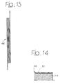
- figures 13, 14 are plan and cross-section views showing a reed 100 made of an electrical conductor arranged in the form of a serpentine defining the reed.
- the various branches of the conductor 100 are destined to be received in the same number of housings 101 on the lateral surface of the respective roller 3 or 4.
- the wire is crossed by an electrical current to heat it.
- the conductor is made of a shape memory alloy.
Landscapes
- Engineering & Computer Science (AREA)
- Chemical & Material Sciences (AREA)
- Combustion & Propulsion (AREA)
- Mechanical Engineering (AREA)
- General Engineering & Computer Science (AREA)
- Transmission Devices (AREA)
- Valve Device For Special Equipments (AREA)
- Vehicle Body Suspensions (AREA)
- Reciprocating, Oscillating Or Vibrating Motors (AREA)
- Other Liquid Machine Or Engine Such As Wave Power Use (AREA)
Abstract
Description
- a first and second roller freely turning on parallel axes,
- transmission devices of the rotation between said first and said second roller, such to make said rollers turn simultaneously in opposite directions,
- a flat, elongated reed, made of shape memory alloy, with two extremity portions, respectively fastened to said first and said second roller and at least partially wound on said rollers with the reed section arranged between one roller and the other forming an S and
- devices for heating said reed to a temperature exceeding a transition temperature, over which the reed tends to wind in the opposite direction with respect to the original direction, so to cause the simultaneous rotation of the two rollers in opposite direction, starting from a resting position, in which the reed is nearly completely wound on the first roller to a final position in which the reed is nearly completely wound on the second roller.
- figures 1, 2 are prospective views of a reed wound as a spiral, made of a memory shape alloy, in free condition, under and over the transition temperature, respectively,
- figure 3 is a diagram illustrating the operating principle of the invention,
- figure 4 is a perspective schematic view of a first form of embodiment of the actuator according to this invention,
- figure 5 is a perspective view of a second form of embodiment,
- figures from 6 to 8 are perspective views illustrating three different possible applications of the actuator according to this invention,
- figure 9 is a front, schematic view of the device in figure 8,
- figure 10 illustrates another possible application of the device according to this invention,
- figures 11, 12 illustrate an additional application and
- figures 13 and 14 illustrate a variation of the reed in the device according to this invention.
Claims (10)
- Shape memory device characterised in that it comprises:a first and second roller (3, 4) freely turning on parallel axes (5, 6),transmission devices (7, 8) of the rotation between said first and said second roller (3, 4), such to make said rollers turn simultaneously in opposite directions,a flat, elongated reed (1), made of shape memory alloy, with two extremity portions (1a, 1b), respectively fastened to said first and said second roller (3, 4) and at least partially wound on said rollers with the reed (1) section arranged between one roller and the other forming an S, anddevices for heating said reed (1) to a temperature exceeding a transition temperature, over which the reed (1) tends to wind in the opposite direction with respect to the original direction, so to cause the simultaneous rotation of the two rollers (3, 4) in opposite direction, starting from a resting position, in which the reed (1) is nearly completely wound on the first roller (4) to a final position in which the reed (1) is nearly completely wound on the second roller (3).
- Actuator according to claim 1, characterised in that said transmission devices consist of two cogs (7, 8), mutually meshed and connected to respective turn on the two rollers (3, 4).
- Actuator according to claim 1, characterised in that at least one of the two rollers (3, 4) is equipped with elastic devices (9) recalling the two rollers to the resting position.
- Actuator according to claim 1, characterised in that two reeds (1, 10) are associated in total to the two rollers (3, 4) arranged so to cause the rotation of the rollers from the resting position to the final position respectively and the return of the rollers from the final position to the resting position.
- Actuator according to claim 1, characterised in that the heating devices can cause an electrical current to cross said reed (1).
- Actuator according to claim 1, characterised in that one of said cogs (7) is connected to turn a screw (13) causing the linear movement of an actuator stem (14).
- Actuator according to claim 1, characterised in that one of said cogs (7) meshes a rack (15) belonging to an actuator stem (14).
- Actuator according to claim 1, characterised in that the shaft of one of said rollers (3, 4) controls a valve lock pin (21).
- Actuator according to claim 1, characterised in that one of the cogs (7) meshes a rack belonging to a gate or sliding door.
- Actuator according to claim 1, characterised in that the two rollers control and turn two rocking levers (19, 20) for locking a pin (16) in a lock.
Applications Claiming Priority (2)
| Application Number | Priority Date | Filing Date | Title |
|---|---|---|---|
| ITTO000408 | 2000-05-02 | ||
| IT2000TO000408A IT1320064B1 (en) | 2000-05-02 | 2000-05-02 | SHAPE MEMORY ACTUATOR DEVICE. |
Publications (3)
| Publication Number | Publication Date |
|---|---|
| EP1164287A2 true EP1164287A2 (en) | 2001-12-19 |
| EP1164287A3 EP1164287A3 (en) | 2002-11-13 |
| EP1164287B1 EP1164287B1 (en) | 2006-04-19 |
Family
ID=11457696
Family Applications (1)
| Application Number | Title | Priority Date | Filing Date |
|---|---|---|---|
| EP01830286A Expired - Lifetime EP1164287B1 (en) | 2000-05-02 | 2001-04-30 | Shape memory actuating device |
Country Status (4)
| Country | Link |
|---|---|
| EP (1) | EP1164287B1 (en) |
| DE (1) | DE60118836T2 (en) |
| ES (1) | ES2260187T3 (en) |
| IT (1) | IT1320064B1 (en) |
Cited By (2)
| Publication number | Priority date | Publication date | Assignee | Title |
|---|---|---|---|---|
| EP2154021A1 (en) | 2008-08-07 | 2010-02-17 | C.R.F. Società Consortile per Azioni | Ergonimic support device for the body of the occupant, for chairs or seats, particularly for motor-vehicle seats |
| EP3032100A3 (en) * | 2014-12-10 | 2016-06-29 | The Boeing Company | Scalable multi-element shape memory alloy rotary motor |
Families Citing this family (1)
| Publication number | Priority date | Publication date | Assignee | Title |
|---|---|---|---|---|
| DE102008027541B4 (en) | 2008-06-10 | 2017-04-06 | Günther Zimmer | Actuating device for pieces of furniture with at least one shape memory element |
Family Cites Families (5)
| Publication number | Priority date | Publication date | Assignee | Title |
|---|---|---|---|---|
| JPS6022079A (en) * | 1983-07-19 | 1985-02-04 | Nhk Spring Co Ltd | Heat engine utilizing shape-memory alloy |
| US4665334A (en) * | 1983-08-26 | 1987-05-12 | The United States Of America As Represented By The Administrator Of The National Aeronautics And Space Administration | Rotary stepping device with memory metal actuator |
| JPS60159378A (en) * | 1984-01-31 | 1985-08-20 | Furukawa Electric Co Ltd:The | Rotary driving mechanism |
| JPH0768940B2 (en) * | 1985-10-30 | 1995-07-26 | 日本発条株式会社 | Rotating device using shape memory alloy |
| US6129181A (en) * | 1998-05-26 | 2000-10-10 | Lockheed Corp | Constant force spring actuator |
-
2000
- 2000-05-02 IT IT2000TO000408A patent/IT1320064B1/en active
-
2001
- 2001-04-30 ES ES01830286T patent/ES2260187T3/en not_active Expired - Lifetime
- 2001-04-30 DE DE60118836T patent/DE60118836T2/en not_active Expired - Fee Related
- 2001-04-30 EP EP01830286A patent/EP1164287B1/en not_active Expired - Lifetime
Cited By (3)
| Publication number | Priority date | Publication date | Assignee | Title |
|---|---|---|---|---|
| EP2154021A1 (en) | 2008-08-07 | 2010-02-17 | C.R.F. Società Consortile per Azioni | Ergonimic support device for the body of the occupant, for chairs or seats, particularly for motor-vehicle seats |
| EP3032100A3 (en) * | 2014-12-10 | 2016-06-29 | The Boeing Company | Scalable multi-element shape memory alloy rotary motor |
| US9885345B2 (en) | 2014-12-10 | 2018-02-06 | The Boeing Company | Scalable multi-element shape memory alloy rotary motor |
Also Published As
| Publication number | Publication date |
|---|---|
| ITTO20000408A0 (en) | 2000-05-02 |
| DE60118836T2 (en) | 2006-09-28 |
| IT1320064B1 (en) | 2003-11-12 |
| EP1164287B1 (en) | 2006-04-19 |
| ITTO20000408A1 (en) | 2001-11-02 |
| EP1164287A3 (en) | 2002-11-13 |
| DE60118836D1 (en) | 2006-05-24 |
| ES2260187T3 (en) | 2006-11-01 |
Similar Documents
| Publication | Publication Date | Title |
|---|---|---|
| US9168828B2 (en) | Actuator with progressive gear | |
| US5396769A (en) | Rotary actuator | |
| JP5944519B2 (en) | Bistable electrical switch with shape memory actuator | |
| US7793497B2 (en) | Actuator with a wound shape-memory element | |
| CN107849984B (en) | Torsion spring | |
| JP2004527710A (en) | Electric motor type adjustment device | |
| EP1593844B1 (en) | Shape memory bistable actuator | |
| EP1164287B1 (en) | Shape memory actuating device | |
| US5121727A (en) | Adjuster for a throttle valve | |
| KR102425193B1 (en) | Swing Type SMA Actuator | |
| US4883983A (en) | Switching system for plural load circuit | |
| US7156074B2 (en) | Throttle device | |
| US4825840A (en) | Exhaust gas recirculation valve construction and method of making the same | |
| US20060130791A1 (en) | Variable cam system | |
| KR100473211B1 (en) | Load control device | |
| US4993144A (en) | Method of making a cyclable electrical switch construction | |
| GB2388177A (en) | Resiliently biased motor-driven valve | |
| CN1040250A (en) | Starter motor for internal combustion engine | |
| US8656796B2 (en) | Operating element movable back and forth by traction elements wound in opposite directions on winding bodies | |
| EP1726467A1 (en) | Sunshade unit for motor-vehicles with a shape memory actuator | |
| KR20100043776A (en) | Sun shade power device for automobile | |
| EP1741882B1 (en) | Variable lift valve operating system for internal combustion engine | |
| JP2004190542A (en) | Engine starter | |
| US8082901B2 (en) | Diesel engine | |
| EP1359355A1 (en) | Valve |
Legal Events
| Date | Code | Title | Description |
|---|---|---|---|
| PUAI | Public reference made under article 153(3) epc to a published international application that has entered the european phase |
Free format text: ORIGINAL CODE: 0009012 |
|
| AK | Designated contracting states |
Kind code of ref document: A2 Designated state(s): AT BE CH CY DE DK ES FI FR GB GR IE IT LI LU MC NL PT SE TR |
|
| AX | Request for extension of the european patent |
Free format text: AL;LT;LV;MK;RO;SI |
|
| PUAL | Search report despatched |
Free format text: ORIGINAL CODE: 0009013 |
|
| AK | Designated contracting states |
Kind code of ref document: A3 Designated state(s): AT BE CH CY DE DK ES FI FR GB GR IE IT LI LU MC NL PT SE TR |
|
| AX | Request for extension of the european patent |
Free format text: AL;LT;LV;MK;RO;SI |
|
| 17P | Request for examination filed |
Effective date: 20030127 |
|
| AKX | Designation fees paid |
Designated state(s): DE ES FR GB IT SE |
|
| GRAP | Despatch of communication of intention to grant a patent |
Free format text: ORIGINAL CODE: EPIDOSNIGR1 |
|
| GRAS | Grant fee paid |
Free format text: ORIGINAL CODE: EPIDOSNIGR3 |
|
| GRAA | (expected) grant |
Free format text: ORIGINAL CODE: 0009210 |
|
| AK | Designated contracting states |
Kind code of ref document: B1 Designated state(s): DE ES FR GB IT SE |
|
| REG | Reference to a national code |
Ref country code: GB Ref legal event code: FG4D |
|
| REG | Reference to a national code |
Ref country code: SE Ref legal event code: TRGR |
|
| REF | Corresponds to: |
Ref document number: 60118836 Country of ref document: DE Date of ref document: 20060524 Kind code of ref document: P |
|
| ET | Fr: translation filed | ||
| REG | Reference to a national code |
Ref country code: ES Ref legal event code: FG2A Ref document number: 2260187 Country of ref document: ES Kind code of ref document: T3 |
|
| PLBE | No opposition filed within time limit |
Free format text: ORIGINAL CODE: 0009261 |
|
| STAA | Information on the status of an ep patent application or granted ep patent |
Free format text: STATUS: NO OPPOSITION FILED WITHIN TIME LIMIT |
|
| 26N | No opposition filed |
Effective date: 20070122 |
|
| PGFP | Annual fee paid to national office [announced via postgrant information from national office to epo] |
Ref country code: SE Payment date: 20070404 Year of fee payment: 7 |
|
| PGFP | Annual fee paid to national office [announced via postgrant information from national office to epo] |
Ref country code: DE Payment date: 20070426 Year of fee payment: 7 |
|
| PGFP | Annual fee paid to national office [announced via postgrant information from national office to epo] |
Ref country code: GB Payment date: 20070425 Year of fee payment: 7 |
|
| PGFP | Annual fee paid to national office [announced via postgrant information from national office to epo] |
Ref country code: IT Payment date: 20070606 Year of fee payment: 7 |
|
| PGFP | Annual fee paid to national office [announced via postgrant information from national office to epo] |
Ref country code: ES Payment date: 20080520 Year of fee payment: 8 Ref country code: FR Payment date: 20080312 Year of fee payment: 8 |
|
| GBPC | Gb: european patent ceased through non-payment of renewal fee |
Effective date: 20080430 |
|
| PG25 | Lapsed in a contracting state [announced via postgrant information from national office to epo] |
Ref country code: DE Free format text: LAPSE BECAUSE OF NON-PAYMENT OF DUE FEES Effective date: 20081101 |
|
| PG25 | Lapsed in a contracting state [announced via postgrant information from national office to epo] |
Ref country code: GB Free format text: LAPSE BECAUSE OF NON-PAYMENT OF DUE FEES Effective date: 20080430 |
|
| PG25 | Lapsed in a contracting state [announced via postgrant information from national office to epo] |
Ref country code: IT Free format text: LAPSE BECAUSE OF NON-PAYMENT OF DUE FEES Effective date: 20080430 |
|
| REG | Reference to a national code |
Ref country code: FR Ref legal event code: ST Effective date: 20091231 |
|
| PG25 | Lapsed in a contracting state [announced via postgrant information from national office to epo] |
Ref country code: FR Free format text: LAPSE BECAUSE OF NON-PAYMENT OF DUE FEES Effective date: 20091222 |
|
| REG | Reference to a national code |
Ref country code: ES Ref legal event code: FD2A Effective date: 20090504 |
|
| PG25 | Lapsed in a contracting state [announced via postgrant information from national office to epo] |
Ref country code: SE Free format text: LAPSE BECAUSE OF NON-PAYMENT OF DUE FEES Effective date: 20080501 Ref country code: ES Free format text: LAPSE BECAUSE OF NON-PAYMENT OF DUE FEES Effective date: 20090504 |