EP1164279A1 - Exhaust gas recirculating valve device - Google Patents
Exhaust gas recirculating valve device Download PDFInfo
- Publication number
- EP1164279A1 EP1164279A1 EP00900927A EP00900927A EP1164279A1 EP 1164279 A1 EP1164279 A1 EP 1164279A1 EP 00900927 A EP00900927 A EP 00900927A EP 00900927 A EP00900927 A EP 00900927A EP 1164279 A1 EP1164279 A1 EP 1164279A1
- Authority
- EP
- European Patent Office
- Prior art keywords
- circular groove
- protrusion
- motor
- exhaust gas
- valve device
- Prior art date
- Legal status (The legal status is an assumption and is not a legal conclusion. Google has not performed a legal analysis and makes no representation as to the accuracy of the status listed.)
- Granted
Links
Images

Classifications
-
- F—MECHANICAL ENGINEERING; LIGHTING; HEATING; WEAPONS; BLASTING
- F02—COMBUSTION ENGINES; HOT-GAS OR COMBUSTION-PRODUCT ENGINE PLANTS
- F02M—SUPPLYING COMBUSTION ENGINES IN GENERAL WITH COMBUSTIBLE MIXTURES OR CONSTITUENTS THEREOF
- F02M26/00—Engine-pertinent apparatus for adding exhaust gases to combustion-air, main fuel or fuel-air mixture, e.g. by exhaust gas recirculation [EGR] systems
- F02M26/65—Constructional details of EGR valves
- F02M26/66—Lift valves, e.g. poppet valves
- F02M26/67—Pintles; Spindles; Springs; Bearings; Sealings; Connections to actuators
-
- F—MECHANICAL ENGINEERING; LIGHTING; HEATING; WEAPONS; BLASTING
- F02—COMBUSTION ENGINES; HOT-GAS OR COMBUSTION-PRODUCT ENGINE PLANTS
- F02M—SUPPLYING COMBUSTION ENGINES IN GENERAL WITH COMBUSTIBLE MIXTURES OR CONSTITUENTS THEREOF
- F02M26/00—Engine-pertinent apparatus for adding exhaust gases to combustion-air, main fuel or fuel-air mixture, e.g. by exhaust gas recirculation [EGR] systems
- F02M26/52—Systems for actuating EGR valves
- F02M26/53—Systems for actuating EGR valves using electric actuators, e.g. solenoids
- F02M26/54—Rotary actuators, e.g. step motors
-
- F—MECHANICAL ENGINEERING; LIGHTING; HEATING; WEAPONS; BLASTING
- F02—COMBUSTION ENGINES; HOT-GAS OR COMBUSTION-PRODUCT ENGINE PLANTS
- F02M—SUPPLYING COMBUSTION ENGINES IN GENERAL WITH COMBUSTIBLE MIXTURES OR CONSTITUENTS THEREOF
- F02M26/00—Engine-pertinent apparatus for adding exhaust gases to combustion-air, main fuel or fuel-air mixture, e.g. by exhaust gas recirculation [EGR] systems
- F02M26/65—Constructional details of EGR valves
- F02M26/72—Housings
- F02M26/73—Housings with means for heating or cooling the EGR valve
Definitions
- the present invention relates to an exhaust gas recirculation valve device disposed in an exhaust gas recirculation passage of an internal combustion engine for example of an automobile.
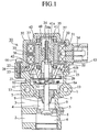
- Fig. 1 is a cross sectional figure showing the internal structure of a conventional exhaust gas recirculation valve device.
- the valve housing 1 has an inlet port 2 communicating with an exhaust system (not shown) of an engine which is an internal combustion engine, an outlet port 3 which communicates with an air intake system (not shown) of the engine and a passage 4 interposed between the outlet port 3 and the inlet port 2.
- a valve seat 5 is press fitted into the passage 4.
- 6 is a valve rod passing through a bushing 7.
- a valve 8 is mounted on the lower end of the valve rod 6 to separate or abut with the valve seat 5.
- 9 is a holder to prevent deposition of substances in the bushing 7.
- 10 is a spring holder which is pushed upwardly by a coil spring 11.
- a through hole 12 is formed in the central section of the spring holder 11.
- the tip 6a of the valve rod 6 is fixed by caulking through the through hole 12.
- the valve rod 6 and the spring holder 10 are integrated by caulking and the valve 8 mounted on the lower section of the valve rod 6 is normally pushed in a closed position with respect to the valve seat 5 by the coil spring 11.
- 13 is a cooling water passage cooling the motor to be described below and the valve body.
- a stepping motor main body functioning as a stator assembly with respect to the rotor section to be discussed below.
- a motor holder 21 is fixed to the lower section of the stepping motor 20 by a clamp screw 23 through an O-ring 22 in order to prevent the entry of water into the stepping motor main body 20.
- a motor brush 25 is disposed to retain the motor shaft 24 in a central opening of the motor holder 21.
- the lower section of the motor shaft 24 is fixed by caulking to the spring holder 26 and a joint 27.
- 28 is a spring which is disposed between the motor holder 21 and the spring holder 26 and which pushes the motor shaft 24 in a direction opening the valve.
- bobbins which are wound coils 31.
- 32 and 33 are yokes.
- a magnetic path is formed through the outer periphery of the yokes 32 and 33.
- 34 are terminals which are electrically connected to coils 31.
- the terminals 34 and a motor housing 35 form a connector.
- 36 is a plate which shields the two coil sections magnetically.
- 37 is a plate preventing resin from flowing into the coil inner section when the motor housing 35 is exterior molded.
- 40 is a magnet.
- 41 is a rotor retaining a magnet.
- the magnet 41 has a threaded section 41a threadably attached to a threaded section 24a of the motor shaft 24 on an inner periphery and an axial stopper 41b of the motor shaft 24.
- 42 are bearings mounted on both ends of the rotor 41.
- 43 is a stopper pin press fitted to the motor shaft 24.
- This type of stepping motor main body 20 maintains a waterproof structure due to the motor holder 21 fixed to the lower section of the stepping motor main body 20 and is mounted on the top section of the valve housing 1 so that the axial centers are aligned by a mounting screw 44.
- the rotor 41 which contains a magnet 40 rotates in a stepwise manner in a direction of valve opening due to a pulsed voltage sent from the control unit (not shown) to the terminals 34 during the valve opening operation.
- the stepwise rotation is converted into linear motion by the threaded section 41a of the rotor 41 and the threaded section 24a of the motor shaft 24 and the motor shaft 24 displaces in a direction of valve opening (downwardly).
- valve rod 6 is depressed by the drive force of the motor shaft 24 against the pushing upward force of the coil spring 11. Also the valve 8 which is mounted on the lower section of the valve rod 6 is lowered and opens with respect to the valve seat 5 and the inlet port 2 and the outlet port 3 are connected by the passage 4.
- the rotor 41 which contains a magnet 40 rotates in a stepwise manner in a direction of valve closure due to a pulsed voltage sent from the control unit (not shown) to the terminals 34 in an operation which is the opposite of the above.
- the motor shaft 24 displaces in a direction of valve closure (upwardly) due to the rotation.
- the valve rod 6 is raised by the upward pushing force of the coil spring 11 and the valve 8 covers the opening of the valve seat 5.
- the waterproofing structure of the stepping motor main body 20 in this type of exhaust gas recirculation valve device is realized by pressing a motor holder 21 by an O-ring 22 onto the lower section of the stepping motor main body 20 and by covering and closing the space between the stepping motor main body 20 and the motor holder 21 with a clamp screw 23 as the O-ring is compressed.
- the present invention is proposed to solve the above problems and has the object of providing an exhaust gas recirculation valve device which maintains a waterproof structure in the stepping motor main body 20 without using an O-ring 22.
- the exhaust gas recirculation valve device is provided with a motor main body which has a motor driving a valve with a valve rod in an opening or a closing direction, and a motor holder which covers the lower opening of the motor main body.
- a motor main body which has a motor driving a valve with a valve rod in an opening or a closing direction
- a motor holder which covers the lower opening of the motor main body.
- One of the lower opening of the motor main body and the upper section of the motor holder is formed a circular groove and the other of the lower opening of the motor main body and the upper section of the motor holder is formed in a protrusion which fits in the circular groove.
- a liquid sealant is applied between the top of the protrusion and the bottom of the circular groove facing the top of the protrusion.
- the present invention is provided with a circular groove which has a bottom and an innermost circular periphery which is adjacent to the bottom and a protrusion which has a top and an innermost circular periphery which is adjacent to the top.
- the present invention is adapted so that the top of the protrusion and the bottom of the circular groove are placed in contact through the liquid sealant with the innermost periphery of the protrusion fitted to the innermost periphery of the circular groove.
- the present invention fixes a section of the outermost periphery of the circular groove by caulking to the outermost periphery of the protrusion, it is possible to fix the motor holder and the motor main body while keeping the space for leading the excess liquid sealant and thus ensure a waterproofing structure in the motor main body.
- the present invention is adapted to make a clearance between the outermost periphery of the circular groove and the outermost periphery of the protrusion facing the outermost periphery greater than the clearance between the innermost periphery of a circular groove and the innermost periphery of the protrusion. In this way, it is possible to form a space to store excess liquid sealant between the respective outermost peripheries of the circular groove and the protrusion.
- the present invention is adopted to form a hollow to store the excess liquid sealant on the top of the outermost periphery of the protrusion. In such a way, it is possible to effectively store the excess liquid sealant in the hollow.
- the present invention is adopted to make a clearance between the bottom of the circular groove and the top of the protrusion facing the bottom of the circular groove greater than the clearance between periphery of the protrusion. In such a way, it is possible to form a space to store the excess liquid sealant between the respective outermost peripheries of the circular groove and the protrusion.
- the present invention is adapted to form a hollow to store excess liquid sealant in the bottom of the outermost periphery of the circular groove. In such a way, it is possible to effectively store excess liquid sealant in the hollow.
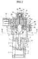
- Fig. 2 is a cross sectional view showing the interior structure of an exhaust gas recirculation valve device according to a first embodiment of the present invention.
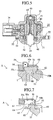
- Fig. 3 is a cross sectional view showing an enlargement of a waterproofing section A of an exhaust gas recirculation valve device as shown in Fig. 2.
- Fig. 4 is a perspective view along the line B - B in Fig. 2.
- Fig. 5 is a cross sectional view along the line C - C in Fig. 4.
- Those components of the first embodiment of the present invention which are the same as those of the conventional exhaust gas recirculation valve device as shown in Fig. 1 are denoted by the same reference numerals and further description will be omitted.
- 45 is a shaft bushing mounted on the top of the rotor 41 and 46 is a bearing for the shaft bushing 45.
- the waterproofing section A shown in Fig. 2 is schematically formed by a circular groove 50 formed with a rectangular cross section on a lower section of the motor housing 35 as shown in Fig. 3, a protrusion 60 which is rectangular in cross section and which is formed on an upper section of the motor holder 21 to fit into the circular groove 50 and a liquid sealant layer 70 interposed between the upper face forming the top of the protrusion 60 and the lower face 50a forming the bottom of the circular groove 50.
- 50b and 50c denote the inner peripheral face and the outer peripheral face of the circular groove 50.
- an outer groove 51 which is concentric with the circular groove 50 is formed on the outer side of the circular groove 50.
- Aplurality of caulking holes 52 are formed at approximately equally spaced intervals on the outer groove 51.
- Wall faces of the caulking holes 52 which are near the circular groove 50 and the protrusion 60 are deformed in a direction covering a section of the protrusion 60 by heat caulking or mechanical caulking. This caulking allows secure fixing of the motor holder 21 to the lower section of the motor housing 35.
- the liquid sealant forming a liquid sealant layer 70 is called a liquid packing or a liquid gasket.
- the liquid sealant is applied in liquid form and solidifies in contact with air after application.
- a sealant such as silicon.
- the liquid sealant is uniformly applied in a fixed amount for example from the tip of a robot manipulator to one or both of the upper surface 61 of the protrusion 60 and the lower face 50a of the circular groove 50. Therefore even if the fit of the seal surface between the upper face 61 of the protrusion 60 and the lower face 50a of the circular groove 50 is disturbed, the liquid sealant is adapted to the fit and thus can maintain a flexible waterproof structure with respect to the surface structure of the sealed face.
- the conventional exhaust gas recirculation valve device shown in Fig. 1 uses an O-ring 22 to maintain the waterproof structure. Even when the O-ring 22 is compressed, a space must be provided in a considerably compressive direction. However in embodiment 1, a slight clearance is sufficient to allow sealing with a liquid sealant layer 70 which thus allows the overall device size to be downscaled.
- This type of liquid sealant layer 70 is extremely thin in comparison with an O-ring 22 and can be adapted to the shape of the sealant face.
- Furthermore the molding of the motor holder 21 and the motor housing 35 is simplified and the design operation is facilitated.
- a circular groove is formed at the motor housing 35 and a protrusion is formed at the motor holder 21.
- a protrusion is formed at the motor holder 21.
- the liquid sealant used in embodiment 1 was a liquid flowing when applied and was hardened when contacted with air. So the possibility of malfunction of the motor drive exists if the liquid sealant enters the rotating section in the motor housing 35.
- Embodiment 2 and embodiment 3 below relate to improvements to prevent the unexpected generation of this type of problem.
- Fig. 6 is a cross sectional view showing a waterproofing section A of an exhaust gas recirculation valve device according to a second embodiment of the present invention.
- invention 2 is related to the arrangement below.
- An inner peripheral face 62 which is the inner peripheral section of the protrusion 60 of the motor holder 21 is fitted into the inner peripheral face 50b which is the inner peripheral section of the circular groove 50 of the motor housing 35.
- Aliquid sealant layer 70 is interposed between the upper face 61 next to the inner peripheral face 62 of the protrusion 60 and the lower face 50a next to the inner peripheral face 50b of the circular groove 50.
- a clearance between the outer peripheral face 63 which is the outermost peripheral section of the protrusion 60 and the outer peripheral face 50c which is the outermost peripheral section of the circular groove 50 is set to be greater than the clearance of the inner peripheral face 62 of the protrusion 60 and the inner peripheral face 50b of the circular groove 50.
- an hollow 54 storing excess liquid sealant is provided on the lower face 50a on the outermost side of the circular groove 50.
- the inner peripheral face 62 which is the inner peripheral section of the protrusion 60 of the motor holder 21 is fitted into the inner peripheral face 50b which is the inner peripheral section of the circular groove 50 of the motor housing 35.
- the clearance of both inner peripheral faces is set to almost zero which prevents seepage of excess liquid sealant comprising the liquid sealant layer 70 into the rotating section of the motor housing 35.
- the clearance between the outer peripheral face 50c which is the outermost peripheral section of the circular groove 50 and the outer peripheral face 63 which is the outermost peripheral section of the protrusion 60 is larger than the clearance on the inner side.
- the upper face 61 of the protrusion 60 is parallel to the lower face 50a of the circular groove 50 in embodiment 2, the upper face 61 may be inclined so that the distance separating the lower face 50a of the circular groove 50 from the inner peripheral face 62 to the outer peripheral face 63 gradually increases.
- the clearance between the upper face 61 and the bottom face 50a may be formed in a tapering shape. This allows effective seepage of excess liquid sealant out of the motor housing 35.
- the use of this type of structure for the upper face 61 in embodiment 2, in particular the use of the structure having an hollow 54 in the circular groove 50 allows excess liquid sealant to be effectively distanced from the entry passage into the motor housing 35. Thus it is possible to ensure prevention of seepage of the liquid sealant into the motor housing 35.
- Fig. 7 is a cross sectional view showing a waterproofing section A of an exhaust gas recirculation valve device according to a third embodiment of the present invention.
- the characteristic of embodiment 3 lies in the provision of a hollow 64 forming a hollowed section on the outer peripheral face 63 and the upper face 61 of the protrusion 60.
- the hollow 64 ensures a space storing excess liquid sealant in the circular groove 50.
- the provision of the hollow 64 firstly allows abutment of the ridge line 55 of the inner peripheral face 50b and the upper face 61 with the inner peripheral face 50b of the circular groove 50. This takes place before the lower face 50a of the circular groove 50 abuts with the upper face 61 of the protrusion 60 and liquid sealant S in introduced between both faces.
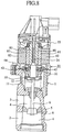
- Fig. 8 is a cross sectional view of the interior structure of an exhaust gas recirculation valve device according to a fourth embodiment of the present invention.
- embodiment 4 is characterized by the use of a DC motor.
- Those components of embodiment 4 which are common to components of the exhaust gas recirculation valve device shown in Fig. 2 and the conventional exhaust gas recirculation valve device as shown in Fig. 1 are denoted by the same reference numerals and additional description will be omitted.
- 80 is a rotor
- 81 is a magnet
- 82 is a yoke.
- the exhaust gas recirculation valve device of the present invention avoids the necessity for use of an O-ring which has a high unit price.
- the overall manufacturing costs of the exhaust gas recirculation valve device can be reduced.
- a liquid sealant which can be adapted to the surface shape of the applied section is used, it is possible to maintain a waterproof structure in the motor main body without threaded fixing. It is possible to prevent entry of excess liquid sealant into the motor main body by making a space for leading liquid sealant between the protrusion which fits in the circular groove and the circular groove between the motor main body and the motor holder.
Landscapes
- Engineering & Computer Science (AREA)
- Chemical & Material Sciences (AREA)
- Combustion & Propulsion (AREA)
- Mechanical Engineering (AREA)
- General Engineering & Computer Science (AREA)
- Exhaust-Gas Circulating Devices (AREA)
- Electrically Driven Valve-Operating Means (AREA)
Abstract
Description
Claims (7)
- An exhaust gas recirculation valve device provided with:a motor main body which has a motor which drives a valve with a valve rod in an opening or a closing direction, anda motor holder which covers a lower opening of the motor main body,one of the lower opening of the motor main body and an upper section of the motor holder are formed as a circular groove and the other of the lower opening of the motor main body and the upper section of the motor holder is formed in a protrusion which fits in the circular groove, liquid sealant is applied between the top of the protrusion and the bottom of the circular groove facing the top of the protrusion.
- An exhaust gas recirculation valve device as defined in Claim 1 wherein:the circular groove has a bottom and an innermost circular periphery which is adjacent to the bottom, and the protrusion has a top and an innermost circular periphery which is adjacent to the top, the top of the protrusion and the bottom of the circular groove are placed in contact through the liquid sealant with the innermost periphery of the protrusion fitted to the innermost periphery of the circular groove.
- An exhaust gas recirculation valve device as defined in Claim 2 wherein:a section of the outermost periphery of the circular groove is fixed by caulking to the outermost periphery of the protrusion.
- An exhaust gas recirculation valve device as defined in Claim 3 wherein:a clearance between the outermost periphery of the circular groove and the outermost periphery of the protrusion facing the outermost periphery of the circular groove is greater than the clearance between the innermost periphery of the circular groove and the innermost periphery of the protrusion.
- An exhaust gas recirculation valve device as defined in Claim 3 wherein:a hollowed section is formed to store excess liquid sealant on the top of the outermost periphery of the protrusion.
- An exhaust gas recirculation valve device as defined in Claim 3 wherein:a clearance between the bottom of the circular groove and the top of the protrusion facing the bottom of the circular groove is greater than the clearance between the innermost periphery of the circular groove and the innermost periphery of the protrusion.
- An exhaust gas recirculation valve device as defined in Claim 3 wherein:a hollow is formed to store excess liquid sealant in the bottom of the outermost periphery of the circular groove.
Applications Claiming Priority (1)
| Application Number | Priority Date | Filing Date | Title |
|---|---|---|---|
| PCT/JP2000/000363 WO2001055579A1 (en) | 2000-01-25 | 2000-01-25 | Exhaust gas recirculating valve device |
Publications (3)
| Publication Number | Publication Date |
|---|---|
| EP1164279A1 true EP1164279A1 (en) | 2001-12-19 |
| EP1164279A4 EP1164279A4 (en) | 2002-09-25 |
| EP1164279B1 EP1164279B1 (en) | 2006-03-22 |
Family
ID=11735615
Family Applications (1)
| Application Number | Title | Priority Date | Filing Date |
|---|---|---|---|
| EP00900927A Expired - Lifetime EP1164279B1 (en) | 2000-01-25 | 2000-01-25 | Exhaust gas recirculating valve device |
Country Status (6)
| Country | Link |
|---|---|
| US (1) | US6672293B1 (en) |
| EP (1) | EP1164279B1 (en) |
| KR (1) | KR20010113853A (en) |
| CN (1) | CN1217096C (en) |
| DE (1) | DE60026820T2 (en) |
| WO (1) | WO2001055579A1 (en) |
Cited By (3)
| Publication number | Priority date | Publication date | Assignee | Title |
|---|---|---|---|---|
| WO2006086236A1 (en) * | 2005-02-08 | 2006-08-17 | Parker-Hannifin Corporation | Electric motor driven valve assembly having stator sealing |
| WO2006097884A1 (en) * | 2005-03-14 | 2006-09-21 | Dell'orto S.P.A. | Egr valve in internal combustion engines actuated by electric motor with rack and pinion |
| WO2013143800A3 (en) * | 2012-03-27 | 2014-01-23 | Ebm-Papst Landshut Gmbh | Gas control valve |
Families Citing this family (7)
| Publication number | Priority date | Publication date | Assignee | Title |
|---|---|---|---|---|
| JP4531359B2 (en) * | 2003-07-18 | 2010-08-25 | 三菱電機株式会社 | motor |
| EP1910686B1 (en) * | 2005-08-02 | 2016-03-09 | Honeywell International Inc. | Variabale geometry nozzle device |
| JP5717556B2 (en) * | 2011-06-22 | 2015-05-13 | 愛三工業株式会社 | EGR valve |
| JP5549696B2 (en) * | 2012-03-02 | 2014-07-16 | 株式会社デンソー | EGR device |
| JP6143651B2 (en) * | 2013-11-14 | 2017-06-07 | 愛三工業株式会社 | Exhaust gas recirculation valve |
| US10197187B2 (en) | 2014-10-31 | 2019-02-05 | Mitsubishi Electric Corporation | Fluid control valve |
| JP6867245B2 (en) * | 2017-06-28 | 2021-04-28 | 日立Astemo株式会社 | Electric drive device and electric power steering device |
Family Cites Families (15)
| Publication number | Priority date | Publication date | Assignee | Title |
|---|---|---|---|---|
| JPS5792042U (en) * | 1980-11-27 | 1982-06-07 | ||
| US4782811A (en) | 1987-03-30 | 1988-11-08 | Robertshaw Controls Company | Exhaust gas recirculation valve construction and method of making the same |
| JPH05106520A (en) * | 1990-12-28 | 1993-04-27 | Aisan Ind Co Ltd | Flow control valve |
| JP2936031B2 (en) | 1992-07-01 | 1999-08-23 | 富士写真フイルム株式会社 | Film unit with lens |
| JP3275152B2 (en) * | 1992-09-03 | 2002-04-15 | 愛三工業株式会社 | Flow control valve |
| JP2978677B2 (en) * | 1993-07-07 | 1999-11-15 | 三菱電機エンジニアリング株式会社 | Electric control valve device |
| JP3068746B2 (en) * | 1994-06-17 | 2000-07-24 | 三菱電機株式会社 | Electric flow control valve |
| JPH0844432A (en) * | 1994-08-02 | 1996-02-16 | Nippondenso Co Ltd | Flow rate control valve |
| JP3201161B2 (en) * | 1994-08-30 | 2001-08-20 | 三菱自動車工業株式会社 | Water pump seal structure |
| US5855195A (en) | 1994-12-26 | 1999-01-05 | Hitachi, Ltd. | Flow control equipment for an internal combustion engine |
| JP3204043B2 (en) * | 1995-06-22 | 2001-09-04 | 日産自動車株式会社 | Flow control valve |
| US5669364A (en) * | 1996-11-21 | 1997-09-23 | Siemens Electric Limited | Exhaust gas recirculation valve installation for a molded intake manifold |
| CN1108446C (en) | 1998-05-06 | 2003-05-14 | 三菱电机株式会社 | Exhaust return valve installation device |
| IT1304100B1 (en) * | 1998-12-14 | 2001-03-07 | Claber Spa | ELECTRONIC CONTROL DEVICE WITH AUTOMATIC PROTECTION AGAINST LOW BATTERY CONDITION FOR TYPE SOLENOID VALVE |
| WO2001048409A1 (en) * | 1999-12-24 | 2001-07-05 | Mitsubishi Denki Kabushiki Kaisha | Exhaust gas recirculation valve device |
-
2000
- 2000-01-25 DE DE60026820T patent/DE60026820T2/en not_active Expired - Lifetime
- 2000-01-25 WO PCT/JP2000/000363 patent/WO2001055579A1/en not_active Ceased
- 2000-01-25 CN CN008053979A patent/CN1217096C/en not_active Expired - Lifetime
- 2000-01-25 EP EP00900927A patent/EP1164279B1/en not_active Expired - Lifetime
- 2000-01-25 US US09/937,360 patent/US6672293B1/en not_active Expired - Lifetime
- 2000-01-25 KR KR1020017012023A patent/KR20010113853A/en not_active Ceased
Cited By (4)
| Publication number | Priority date | Publication date | Assignee | Title |
|---|---|---|---|---|
| WO2006086236A1 (en) * | 2005-02-08 | 2006-08-17 | Parker-Hannifin Corporation | Electric motor driven valve assembly having stator sealing |
| WO2006097884A1 (en) * | 2005-03-14 | 2006-09-21 | Dell'orto S.P.A. | Egr valve in internal combustion engines actuated by electric motor with rack and pinion |
| WO2013143800A3 (en) * | 2012-03-27 | 2014-01-23 | Ebm-Papst Landshut Gmbh | Gas control valve |
| US9371931B2 (en) | 2012-03-27 | 2016-06-21 | Ebm-Papst Landshut Gmbh | Gas control valve |
Also Published As
| Publication number | Publication date |
|---|---|
| KR20010113853A (en) | 2001-12-28 |
| DE60026820D1 (en) | 2006-05-11 |
| CN1344351A (en) | 2002-04-10 |
| DE60026820T2 (en) | 2007-01-18 |
| EP1164279B1 (en) | 2006-03-22 |
| WO2001055579A1 (en) | 2001-08-02 |
| EP1164279A4 (en) | 2002-09-25 |
| CN1217096C (en) | 2005-08-31 |
| US6672293B1 (en) | 2004-01-06 |
Similar Documents
| Publication | Publication Date | Title |
|---|---|---|
| KR101566614B1 (en) | Exhaust system for internal combustion engine | |
| EP1191210B1 (en) | Throttle device of internal combustion engine | |
| US5184593A (en) | Flow control valve | |
| EP1164279B1 (en) | Exhaust gas recirculating valve device | |
| US6591809B2 (en) | Throttle device for internal-combustion engine | |
| US6923157B2 (en) | Throttle device for internal combustion engine | |
| EP1010887B1 (en) | Device for mounting exhaust gas reflux valve | |
| US20090294713A1 (en) | Flow rate control valve | |
| KR20150032473A (en) | Actuator and valve arrangement | |
| JP2004144039A (en) | Electronically controlled throttle control | |
| US11668407B2 (en) | Motorised ball valve | |
| US20020174858A1 (en) | Exhaust gas recirculation valve | |
| KR0167356B1 (en) | Electromagnetic rotary actuator | |
| KR100390763B1 (en) | Flow Control Valve | |
| EP0982838B1 (en) | Motorized flow rate control valve | |
| WO2003006815A1 (en) | Mounting device for exhaust gas recirculation valve | |
| CN1146699C (en) | Exhaust gas recirculation valve unit | |
| CN222797588U (en) | Throttle device | |
| WO2001061225A1 (en) | Motor type flow control valve and method of manufacturing the flow control valve | |
| JP3611969B2 (en) | solenoid | |
| JP3702657B2 (en) | Valve drive motor with improved sealing performance | |
| JPH11173430A (en) | Fluid shut-off valve | |
| JPH0488276A (en) | Control valve device for engine | |
| KR20010014212A (en) | Mounting Device for Exhaust Gas Re-circulation Valve | |
| JPS60192107A (en) | Fluid pressure-operated actuator |
Legal Events
| Date | Code | Title | Description |
|---|---|---|---|
| PUAI | Public reference made under article 153(3) epc to a published international application that has entered the european phase |
Free format text: ORIGINAL CODE: 0009012 |
|
| 17P | Request for examination filed |
Effective date: 20010821 |
|
| AK | Designated contracting states |
Kind code of ref document: A1 Designated state(s): AT BE CH CY DE DK ES FI FR GB GR IE IT LI LU MC NL PT SE |
|
| A4 | Supplementary search report drawn up and despatched |
Effective date: 20020814 |
|
| AK | Designated contracting states |
Kind code of ref document: A4 Designated state(s): AT BE CH CY DE DK ES FI FR GB GR IE IT LI LU MC NL PT SE |
|
| RBV | Designated contracting states (corrected) |
Designated state(s): DE |
|
| 17Q | First examination report despatched |
Effective date: 20040804 |
|
| GRAP | Despatch of communication of intention to grant a patent |
Free format text: ORIGINAL CODE: EPIDOSNIGR1 |
|
| GRAS | Grant fee paid |
Free format text: ORIGINAL CODE: EPIDOSNIGR3 |
|
| GRAA | (expected) grant |
Free format text: ORIGINAL CODE: 0009210 |
|
| AK | Designated contracting states |
Kind code of ref document: B1 Designated state(s): DE |
|
| RAP2 | Party data changed (patent owner data changed or rights of a patent transferred) |
Owner name: MITSUBISHI DENKI KABUSHIKI KAISHA |
|
| REF | Corresponds to: |
Ref document number: 60026820 Country of ref document: DE Date of ref document: 20060511 Kind code of ref document: P |
|
| PLBI | Opposition filed |
Free format text: ORIGINAL CODE: 0009260 |
|
| 26 | Opposition filed |
Opponent name: GUSTAV WAHLER GMBH U. CO. KG Effective date: 20061201 |
|
| PLAX | Notice of opposition and request to file observation + time limit sent |
Free format text: ORIGINAL CODE: EPIDOSNOBS2 |
|
| PLBB | Reply of patent proprietor to notice(s) of opposition received |
Free format text: ORIGINAL CODE: EPIDOSNOBS3 |
|
| PLAY | Examination report in opposition despatched + time limit |
Free format text: ORIGINAL CODE: EPIDOSNORE2 |
|
| PLCK | Communication despatched that opposition was rejected |
Free format text: ORIGINAL CODE: EPIDOSNREJ1 |
|
| PLBN | Opposition rejected |
Free format text: ORIGINAL CODE: 0009273 |
|
| STAA | Information on the status of an ep patent application or granted ep patent |
Free format text: STATUS: OPPOSITION REJECTED |
|
| 27O | Opposition rejected |
Effective date: 20091101 |
|
| REG | Reference to a national code |
Ref country code: DE Ref legal event code: R084 Ref document number: 60026820 Country of ref document: DE |
|
| REG | Reference to a national code |
Ref country code: DE Ref legal event code: R084 Ref document number: 60026820 Country of ref document: DE Effective date: 20110506 |
|
| PGFP | Annual fee paid to national office [announced via postgrant information from national office to epo] |
Ref country code: DE Payment date: 20190115 Year of fee payment: 20 |
|
| PGFP | Annual fee paid to national office [announced via postgrant information from national office to epo] |
Ref country code: DE Payment date: 20190115 Year of fee payment: 20 |
|
| REG | Reference to a national code |
Ref country code: DE Ref legal event code: R071 Ref document number: 60026820 Country of ref document: DE |