EP1164278B1 - Stirling cycle engine - Google Patents
Stirling cycle engine Download PDFInfo
- Publication number
- EP1164278B1 EP1164278B1 EP01113348A EP01113348A EP1164278B1 EP 1164278 B1 EP1164278 B1 EP 1164278B1 EP 01113348 A EP01113348 A EP 01113348A EP 01113348 A EP01113348 A EP 01113348A EP 1164278 B1 EP1164278 B1 EP 1164278B1
- Authority
- EP
- European Patent Office
- Prior art keywords
- cylinder
- mount
- cycle engine
- stirling cycle
- casing
- Prior art date
- Legal status (The legal status is an assumption and is not a legal conclusion. Google has not performed a legal analysis and makes no representation as to the accuracy of the status listed.)
- Expired - Lifetime
Links
- 239000000463 material Substances 0.000 claims abstract description 9
- 229910000838 Al alloy Inorganic materials 0.000 claims description 4
- PNEYBMLMFCGWSK-UHFFFAOYSA-N Alumina Chemical compound [O-2].[O-2].[O-2].[Al+3].[Al+3] PNEYBMLMFCGWSK-UHFFFAOYSA-N 0.000 claims description 2
- 239000011347 resin Substances 0.000 claims 2
- 229920005989 resin Polymers 0.000 claims 2
- 230000006835 compression Effects 0.000 description 12
- 238000007906 compression Methods 0.000 description 12
- 238000003754 machining Methods 0.000 description 8
- 238000004891 communication Methods 0.000 description 6
- 238000000034 method Methods 0.000 description 4
- 230000002093 peripheral effect Effects 0.000 description 4
- 229910000831 Steel Inorganic materials 0.000 description 2
- 238000005266 casting Methods 0.000 description 2
- 238000005242 forging Methods 0.000 description 2
- 238000004519 manufacturing process Methods 0.000 description 2
- 229910052751 metal Inorganic materials 0.000 description 2
- 239000002184 metal Substances 0.000 description 2
- 238000000465 moulding Methods 0.000 description 2
- 230000000717 retained effect Effects 0.000 description 2
- 230000002441 reversible effect Effects 0.000 description 2
- 239000010959 steel Substances 0.000 description 2
- 239000000956 alloy Substances 0.000 description 1
- 230000003247 decreasing effect Effects 0.000 description 1
- 230000005489 elastic deformation Effects 0.000 description 1
- 229910001092 metal group alloy Inorganic materials 0.000 description 1
- 239000007769 metal material Substances 0.000 description 1
- ISWSIDIOOBJBQZ-UHFFFAOYSA-N phenol group Chemical group C1(=CC=CC=C1)O ISWSIDIOOBJBQZ-UHFFFAOYSA-N 0.000 description 1
- 238000004904 shortening Methods 0.000 description 1
- 239000010935 stainless steel Substances 0.000 description 1
- 229910001220 stainless steel Inorganic materials 0.000 description 1
- 229920003002 synthetic resin Polymers 0.000 description 1
- 239000000057 synthetic resin Substances 0.000 description 1
Images

Classifications
-
- F—MECHANICAL ENGINEERING; LIGHTING; HEATING; WEAPONS; BLASTING
- F02—COMBUSTION ENGINES; HOT-GAS OR COMBUSTION-PRODUCT ENGINE PLANTS
- F02G—HOT GAS OR COMBUSTION-PRODUCT POSITIVE-DISPLACEMENT ENGINE PLANTS; USE OF WASTE HEAT OF COMBUSTION ENGINES; NOT OTHERWISE PROVIDED FOR
- F02G1/00—Hot gas positive-displacement engine plants
- F02G1/04—Hot gas positive-displacement engine plants of closed-cycle type
- F02G1/043—Hot gas positive-displacement engine plants of closed-cycle type the engine being operated by expansion and contraction of a mass of working gas which is heated and cooled in one of a plurality of constantly communicating expansible chambers, e.g. Stirling cycle type engines
-
- F—MECHANICAL ENGINEERING; LIGHTING; HEATING; WEAPONS; BLASTING
- F02—COMBUSTION ENGINES; HOT-GAS OR COMBUSTION-PRODUCT ENGINE PLANTS
- F02G—HOT GAS OR COMBUSTION-PRODUCT POSITIVE-DISPLACEMENT ENGINE PLANTS; USE OF WASTE HEAT OF COMBUSTION ENGINES; NOT OTHERWISE PROVIDED FOR
- F02G2243/00—Stirling type engines having closed regenerative thermodynamic cycles with flow controlled by volume changes
- F02G2243/02—Stirling type engines having closed regenerative thermodynamic cycles with flow controlled by volume changes having pistons and displacers in the same cylinder
- F02G2243/04—Crank-connecting-rod drives
-
- F—MECHANICAL ENGINEERING; LIGHTING; HEATING; WEAPONS; BLASTING
- F02—COMBUSTION ENGINES; HOT-GAS OR COMBUSTION-PRODUCT ENGINE PLANTS
- F02G—HOT GAS OR COMBUSTION-PRODUCT POSITIVE-DISPLACEMENT ENGINE PLANTS; USE OF WASTE HEAT OF COMBUSTION ENGINES; NOT OTHERWISE PROVIDED FOR
- F02G2280/00—Output delivery
- F02G2280/10—Linear generators
-
- F—MECHANICAL ENGINEERING; LIGHTING; HEATING; WEAPONS; BLASTING
- F05—INDEXING SCHEMES RELATING TO ENGINES OR PUMPS IN VARIOUS SUBCLASSES OF CLASSES F01-F04
- F05C—INDEXING SCHEME RELATING TO MATERIALS, MATERIAL PROPERTIES OR MATERIAL CHARACTERISTICS FOR MACHINES, ENGINES OR PUMPS OTHER THAN NON-POSITIVE-DISPLACEMENT MACHINES OR ENGINES
- F05C2225/00—Synthetic polymers, e.g. plastics; Rubber
- F05C2225/08—Thermoplastics
Definitions
- the present invention relates to a free-piston type stirling cycle engine, particularly to the structure of a cylinder mounted inside an apparatus body.
- a stirling cycle engine allows a piston to reciprocate in a cylinder in the axial direction, so that when the piston is shifted toward a displacer, a gas inside a compression chamber formed between the piston and the displacer is compressed, and then it passes through a heat dissipating fin, a regenerator and an endothermic or heat absorbing fin, to reach an expansion chamber formed between the tip end of the displacer and the tip end of a casing, thus pushing the displacer downward.
- the above-mentioned cylinder has heretofore been produced by machining a pole-shaped metallic material, such as aluminum alloy, steels of various kinds or the like, and there has been a mount portion provided in the cylinder, for the purpose of fixing the cylinder to the casing and retaining a drive mechanism for reciprocating the piston.
- mount portion would be machined with the same being integral with the cylinder.
- an approximate configuration may be first obtained by forging or casting a material, and then machining the material. In that case, however, the amount of metal filing is decreased, but the costs are eventually increased due to the forging or casting process prior to the machining process, and thus there is no substantial difference in final costs.
- a stirling cycle engine comprising: a casing which at least includes a substantially cylinder-shaped cylindrical portion; a metallic cylinder that is coaxially inserted into the cylindrical portion of the casing; a piston inserted into the cylinder; a drive mechanism for reciprocally driving the piston; and a mount which is attached to an outer periphery of said cylinder for fixing the cylinder to said casing and retaining said drive mechanism, wherein said mount is made of a material of low heat conductance, substantially disc-shaped, having an attachment hole in the center thereof.
- a stirling cycle engine as set forth in the preceding paragraph, further comprising: a bar and a male screw which are formed around the outer periphery of said cylinder coaxially therewith; and a recess and a female screw which are formed around an inner periphery of said mount coaxially therewith so that said bar may be inserted into the recess with a slight clearance therebetween and the said male screw may be screwed into the female screw.
- the mount can be quite easily and firmly attached to the cylinder.
- reference numeral 1 designates a casing constructed of a substantially cylinder-shaped cylindrical portion 2 and a main body portion 3.
- the cylindrical portion 2 is made from stainless steel or the like, comprising a proximal portion 4, an intermediate portion 5 and a distal portion 6 which are integrally formed with one another.
- a cylinder 7 that is coaxially inserted into the same, extending to the main body 3.
- a displacer 8 Inside the cylinder 7 is provided a displacer 8 in a manner capable of sliding in the axial direction. Between the distal end of the displacer 8 and the distal portion 6 of the cylindrical portion 2 is formed an expansion chamber E, while a space 9 provides the communication of the inside of the cylinder 7 with the outside thereof.
- a regenerator 10 Around the outer periphery of the cylinder 7 in the intermediate portion 5 is provided a regenerator 10, while in the proximal portion 4 is provided a communication hole 11 for allowing the inside of the cylinder 7 to communicate with the outside thereof.
- a heat absorbing fin 12 Around the outer periphery of the distal end of the cylinder 7 is provided a heat absorbing fin 12, while around the outer periphery of the cylinder 7 between the regenerator 10 and the communication hole 11 is provided a heat dissipating fin 13.
- a path of flow is formed to extend from the distal end of the inside of the cylinder 7, through the space 9, heat absorbing fin 12, regenerator 10, heat dissipating fin 13 and communication hole 11, up to the compression chamber C inside the cylinder 7.
- a piston 15 is housed in the cylinder 7 in a manner capable of sliding in the axial direction.
- the proximal portion of the piston 15 is coaxially connected to a drive mechanism 16.
- the drive mechanism 16, which serves to reciprocally drive the piston 15, comprises a frame 17 which is shaped into a short cylinder configuration, a group of magnets 18 fixed to one end of the frame 17, and an annular electromagnetic coil 19 provided adjacent to the outer periphery of the group of magnets 18.
- the group of magnets 18 is constructed by disposing plate-like permanent magnets 20 in a cylindrical arrangement.
- Reference numeral 21 designates a rod for control of the movement of the displacer 8, while reference numerals 22 and 23 are vortical blade springs.
- the aforesaid electromagnetic coil 19 is wound around a laminated core 24, said laminated core 24 being provided integrally with the core 19 and etc. by a holder 25 provided at both sides thereof.
- the cylinder 7 is made from aluminum alloy, having at least the inner surface thereof hardened, by so-called almite treatment or the like.
- the outer peripheral surface of the cylinder 7 is formed with a protrusion or bar 26 which slightly protrudes therefrom in a coaxial manner with respect to the cylinder 7.
- the bar 26 is worked so as to allow the outer periphery thereof to take a shape approximated to a perfect circle, adjacent to which is provided a male-threaded portion or male screw 27.
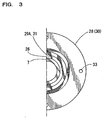
- the mount 28 is resin-made, comprising: an attachment portion 29 which is shaped into a short cylinder configuration, defining an attachment hole 29A in the center thereof; and a flange 30 formed integrally with the attachment portion 29.
- the inner periphery of the attachment portion 29 is formed with a recess 31 provided coaxially with the attachment portion 29.
- the recess 31 thus peripherally formed defines an inside diameter substantially equal to the outside diameter of the aforesaid bar 26 that is also peripherally formed, with the inner periphery of the recess 31 being approximated to a perfect circle.
- a female-threaded portion or female screw 32 which can engage the male screw 27.
- the flange 30 is provided with a plurality of through-holes 33 arranged at equal intervals.
- the mount 28 fixed to the cylinder 7 serves to fix the cylinder 7 to the casing 1 and retain the drive mechanism 16. More specifically, a bracket 34 protruding inwardly from the inner periphery of the distal portion of the main body 3 and the aforesaid flange 30 are each formed with a through-hole 33, into which is inserted a bolt 35 which is then tightened by a nut 36 to thereby fix the cylinder 7 to the casing 1, while a holder 25 has a distal portion abutted to the flange 30, whereby the laminated core 24 and the drive mechanism 16 are retained by the mount 28.
- the cylinder 7 is formed into an approximately cylindrical shape by machining a pole-shaped aluminum alloy material which is slightly thicker than the outside diameter of the aforesaid bar 26 so that the inner periphery of the cylinder 7 and the outer periphery of the bar 26 may define a perfect-circle-shaped section, each of which extending coaxially, defining a constant diameter in the respective axial direction.
- the mount 28 is formed by integral molding, the inner periphery of the recess 31 may be machined if necessary so that the section thereof may take a perfect-circle shape, extending coaxially, defining a constant diameter in the axial direction.
- the mount 28 is made of synthetic resin of a low heat conductance, the heat emitted from the drive mechanism 16 is capable of being prevented from transferring to the cylinder 7 via the mount 28, or to the compression chamber C inside the cylinder 7, so that the thermal expansion of the cylinder 7 due to the heat from the drive mechanism 16 can be prevented, to thereby avoid the damage to the stirling cycle operation.
- a stirling cycle engine comprises: the casing 1 at least including the substantially cylinder-shaped cylindrical portion 2; the metallic cylinder 7 coaxially inserted into the cylindrical portion 2 of the casing 1; the piston 15 inserted into the cylinder 7; the drive mechanism 16 for reciprocally driving the piston 15; and the mount 28 attached to the outer periphery of the cylinder 7, said mount 28 being provided for fixing the cylinder 7 to the casing 1 and retaining the drive mechanism 16.
- the cylinder 7 and the mount 28 are constructed independently of each other such that the mount 28 is attached to the outer periphery of the cylinder 7, the easier working thereof is resulted, thus shortening the working time, improving productivity, and reducing working costs.
- the mount 28 is made of material of low heat conductance, approximately disc-shaped, having the attachment hole 29A in the center thereof, the heat emitted from the drive mechanism 16 is capable of being prevented from transferring to the cylinder 7 via the mount 28, or to the compression chamber C inside the cylinder 7, so that the thermal expansion of the cylinder 7 due to the heat from the drive mechanism 16 can be prevented, to thereby avoid the damage to the stirling cycle operation.
- the outer peripheral surface of the cylinder 7 is formed with the bar 26 and the male screw 27 provided in a coaxial manner with respect to the cylinder 7, while the inner periphery of the mount 28 is formed with the recess 31 and the female screw 32 provided coaxially therewith so that the said bar 26 may be inserted into the recess 31 with a slight clearance therebetween and the said male screw 27 may be screwed into the female screw 32, whereby the mount 28 can be easily and securely attached to the cylinder 7, thus realizing accurate assembling, using a simple structure.
- the present invention should not be limited to the foregoing embodiments, but may be modified within the scope of the invention.
- the material of said cylinder may be steel or any other type of metallic alloy if it meets the requirements including hardness and strength.
- the male screw is provided adjacent to the distal end of the bar in the foregoing embodiment, the bar may be provided adjacent to the distal end of the male screw. In that case, the positional relationship between the recess of the mount and the female screw thereof should be reversed.
- the flange is integrally provided at the proximal end of the attachment portion in the foregoing embodiment, it may be provided at any other suitable portion thereof, such as the distal end of thereof.
Abstract
Description
- The present invention relates to a free-piston type stirling cycle engine, particularly to the structure of a cylinder mounted inside an apparatus body.
- A stirling cycle engine allows a piston to reciprocate in a cylinder in the axial direction, so that when the piston is shifted toward a displacer, a gas inside a compression chamber formed between the piston and the displacer is compressed, and then it passes through a heat dissipating fin, a regenerator and an endothermic or heat absorbing fin, to reach an expansion chamber formed between the tip end of the displacer and the tip end of a casing, thus pushing the displacer downward. On the other hand, when the piston is shifted to the opposite direction, then the inside of the compression chamber is subjected to a negative pressure, so that the gas returns from the expansion chamber to the compression chamber inside the cylinder, via the heat absorbing fin, the regenerator and the heat dissipating fin, thereby pushing the displacer upwardly. Through such steps, the operation of a reversible cycle consisting of isothermal change and isovolumic change is carried out, whereby the temperature of the heat absorbing fin mounted to the peripheral tip end of the cylinder is lowered, while the temperature of the heat dissipating fin mounted to the outer periphery of a base is raised.
- Conventionally, the above-mentioned cylinder has heretofore been produced by machining a pole-shaped metallic material, such as aluminum alloy, steels of various kinds or the like, and there has been a mount portion provided in the cylinder, for the purpose of fixing the cylinder to the casing and retaining a drive mechanism for reciprocating the piston. For improving accuracy, such mount portion would be machined with the same being integral with the cylinder.
- However, for forming the cylinder integral with such mount by means of machining process, it is necessary to machine a metallic pole material that is thicker than the outer dimension of the mount, so that a considerable portion of the material becomes metal filing, thus consuming longer time for machining, leading to inferior productivity. Further, as the outer dimension of the mount is comparatively large, a large-sized machining machine is needed, thus causing the increase of costs.
- For an alternative method for forming the cylinder with such mount, it is proposed that an approximate configuration may be first obtained by forging or casting a material, and then machining the material. In that case, however, the amount of metal filing is decreased, but the costs are eventually increased due to the forging or casting process prior to the machining process, and thus there is no substantial difference in final costs.
- As a further conceivable method for forming the cylinder with such mount, the use of phenolic molding may be considered, which, however, requires a draft angle, and thus at least the machining inside the cylinder is needed, thus leading to a likelihood to degrade the accuracy due to thermal expansion or elastic deformation. As is apparent from the above-mentioned, conventional manufacture of a cylinder integrally formed with a mount has had problems in respect of costs and accuracy.
- In addition, as the drive mechanism retained by the mount in a stirling cycle engine reaches a high temperature, there is a risk that the heat of the drive mechanism transfers from the mount to the cylinder, and then transfers to the compression space inside the cylinder, so that the thermal expansion of the cylinder is liable to occur to thereby produce a larger clearance between the cylinder and the piston, and/or the flow of the heat into the compression space is liable to damage the stirling cycle operation itself. Conversely, there has been a risk that the heat inside the compression space transfers to the drive mechanism via the cylinder and the mount, so that the drive mechanism is overheated.
- Accordingly, it is a main object of the present invention to provide a stirling cycle engine in which a cylinder with a mount is able to be easily manufactured and installed.
- It is another object of the present invention to provide a stirling cycle engine which is subjected to less damage by heat emitted from a drive mechanism.
- To attain the above objects, there is provided a stirling cycle engine, comprising: a casing which at least includes a substantially cylinder-shaped cylindrical portion; a metallic cylinder that is coaxially inserted into the cylindrical portion of the casing; a piston inserted into the cylinder; a drive mechanism for reciprocally driving the piston; and a mount which is attached to an outer periphery of said cylinder for fixing the cylinder to said casing and retaining said drive mechanism, wherein said mount is made of a material of low heat conductance, substantially disc-shaped, having an attachment hole in the center thereof. Thus, working process therefor becomes easier, so that the working time is shortened, to thereby improve productivity, and reduce working costs. Further, The heat emitted from the drive mechanism is less likely to be transferred to the cylinder or to the compression chamber inside the cylinder via the mount.
- From another aspect of the invention, there is provided a stirling cycle engine as set forth in the preceding paragraph, further comprising: a bar and a male screw which are formed around the outer periphery of said cylinder coaxially therewith; and a recess and a female screw which are formed around an inner periphery of said mount coaxially therewith so that said bar may be inserted into the recess with a slight clearance therebetween and the said male screw may be screwed into the female screw. Thus, the mount can be quite easily and firmly attached to the cylinder.
- Other objects, features and advantages of the invention will be apparent to those skilled in the art from the following description of the preferred embodiments of the invention, wherein reference is made to the accompanying drawings, of which:
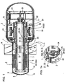
- Fig.1 is a section of a stirling cycle engine according to an embodiment of the invention, while Fig.1a is a partly enlarged section thereof.
- Fig.2 is a section of an embodiment of the invention, particularly illustrating a cross-sectional view of the neighborhood of a cylinder.
- Fig. 3 is a transverse section of an embodiment of the invention, particularly illustrating a semi-sectional view of the neighborhood of the cylinder.
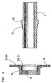
- Fig.4 is an exploded cross-sectional view showing the neighborhood of the cylinder of an embodiment of the invention.
- Hereinafter is described a preferred embodiment of the present invention with reference to Figs.1 through 4, in which reference numeral 1 designates a casing constructed of a substantially cylinder-shaped
cylindrical portion 2 and amain body portion 3. Thecylindrical portion 2 is made from stainless steel or the like, comprising aproximal portion 4, an intermediate portion 5 and a distal portion 6 which are integrally formed with one another. - Inside the
cylindrical portion 2 is provided acylinder 7 that is coaxially inserted into the same, extending to themain body 3. Inside thecylinder 7 is provided adisplacer 8 in a manner capable of sliding in the axial direction. Between the distal end of thedisplacer 8 and the distal portion 6 of thecylindrical portion 2 is formed an expansion chamber E, while a space 9 provides the communication of the inside of thecylinder 7 with the outside thereof. Around the outer periphery of thecylinder 7 in the intermediate portion 5 is provided aregenerator 10, while in theproximal portion 4 is provided a communication hole 11 for allowing the inside of thecylinder 7 to communicate with the outside thereof. Around the outer periphery of the distal end of thecylinder 7 is provided aheat absorbing fin 12, while around the outer periphery of thecylinder 7 between theregenerator 10 and the communication hole 11 is provided aheat dissipating fin 13. Thus, a path of flow is formed to extend from the distal end of the inside of thecylinder 7, through the space 9,heat absorbing fin 12,regenerator 10,heat dissipating fin 13 and communication hole 11, up to the compression chamber C inside thecylinder 7. - To the outer periphery of the
proximal portion 4 is mounted an outerheat dissipating fin 14. Inside themain body 3, apiston 15 is housed in thecylinder 7 in a manner capable of sliding in the axial direction. The proximal portion of thepiston 15 is coaxially connected to adrive mechanism 16. Thedrive mechanism 16, which serves to reciprocally drive thepiston 15, comprises aframe 17 which is shaped into a short cylinder configuration, a group ofmagnets 18 fixed to one end of theframe 17, and an annularelectromagnetic coil 19 provided adjacent to the outer periphery of the group ofmagnets 18. The group ofmagnets 18 is constructed by disposing plate-likepermanent magnets 20 in a cylindrical arrangement.Reference numeral 21 designates a rod for control of the movement of thedisplacer 8, whilereference numerals electromagnetic coil 19 is wound around a laminatedcore 24, said laminatedcore 24 being provided integrally with thecore 19 and etc. by aholder 25 provided at both sides thereof. - The
cylinder 7 is made from aluminum alloy, having at least the inner surface thereof hardened, by so-called almite treatment or the like. The outer peripheral surface of thecylinder 7 is formed with a protrusion orbar 26 which slightly protrudes therefrom in a coaxial manner with respect to thecylinder 7. Thebar 26 is worked so as to allow the outer periphery thereof to take a shape approximated to a perfect circle, adjacent to which is provided a male-threaded portion ormale screw 27. - A
mount 28, provided for fixing thecylinder 7 to thecylindrical portion 2 of the casing 1 and retaining the said drive mechanism 1, is attached to the outside of thebar 26 and themale screw 27. Themount 28 is resin-made, comprising: anattachment portion 29 which is shaped into a short cylinder configuration, defining anattachment hole 29A in the center thereof; and aflange 30 formed integrally with theattachment portion 29. The inner periphery of theattachment portion 29 is formed with arecess 31 provided coaxially with theattachment portion 29. Therecess 31 thus peripherally formed defines an inside diameter substantially equal to the outside diameter of theaforesaid bar 26 that is also peripherally formed, with the inner periphery of therecess 31 being approximated to a perfect circle. Further, adjacent to therecess 31 is formed a female-threaded portion orfemale screw 32 which can engage themale screw 27. Theflange 30 is provided with a plurality of through-holes 33 arranged at equal intervals. By engaging thefemale screw 32 of themount 28 with themale screw 27 of thecylinder 7, themount 28 is attached to the outer periphery of thecylinder 7. At that time of moment, thebar 26 on the outer periphery of thecylinder 7 is inserted into therecess 31 of themount 28, whereby themount 28 is properly positioned, coaxially with thecylinder 7. - As is apparent from the foregoing, the
mount 28 fixed to thecylinder 7 serves to fix thecylinder 7 to the casing 1 and retain thedrive mechanism 16. More specifically, abracket 34 protruding inwardly from the inner periphery of the distal portion of themain body 3 and theaforesaid flange 30 are each formed with a through-hole 33, into which is inserted abolt 35 which is then tightened by anut 36 to thereby fix thecylinder 7 to the casing 1, while aholder 25 has a distal portion abutted to theflange 30, whereby the laminatedcore 24 and thedrive mechanism 16 are retained by themount 28. - Next, a method for manufacturing the
cylinder 7 and themount 28 will be described. Thecylinder 7 is formed into an approximately cylindrical shape by machining a pole-shaped aluminum alloy material which is slightly thicker than the outside diameter of theaforesaid bar 26 so that the inner periphery of thecylinder 7 and the outer periphery of thebar 26 may define a perfect-circle-shaped section, each of which extending coaxially, defining a constant diameter in the respective axial direction. On the other hand, whilst themount 28 is formed by integral molding, the inner periphery of therecess 31 may be machined if necessary so that the section thereof may take a perfect-circle shape, extending coaxially, defining a constant diameter in the axial direction. By screwing themale screw 27 into thefemale screw 32 of themount 28, themount 28 is firmly attached to the outer periphery of thecylinder 7. - With the structure thus made, an alternate current is allowed to flow in the
electromagnetic coil 19, so that an alternate magnetic field occurs to thereby develop a force to move the group ofmagnets 18 toward the axial direction. This force allows thepiston 15 to make a reciprocal movement in the axial direction inside thecylinder 7. Thus, when thepiston 15 moves toward thedisplacer 8, a gas within the compression chamber C formed between thepiston 15 and thedisplacer 8 is compressed, and then passes through the communication hole 11,heat dissipating fin 13,regenerator 10,heat absorbing fin 12, and the space 9 to reach the expansion chamber E formed between the distal end of thedisplacer 8 and the distal portion 6 of thecylindrical portion 2, whereby thedisplacer 8 is pushed downward. On the other hand, when thepiston 15 moves away from thedisplacer 8, a negative pressure is applied to the interior of the compression chamber C, and thus the gas is allowed to return to the chamber C inside thecylinder 7, through the space 9,heat absorbing fin 12,regenerator 10,heat dissipating fin 13, and communication hole 11, whereby thedisplacer 8 is pushed upward. - Through such steps, the operation of a reversible cycle consisting of isothermal change and isovolumic change is carried out, whereby the temperature of the
heat absorbing fin 12 attached to the peripheral tip end of thecylinder 7 is lowered, while the temperature of the outerheat dissipating fin 14 attached to the outer periphery of thebase 4 is raised. - It should be noted that during the above operation, as the
mount 28 is made of synthetic resin of a low heat conductance, the heat emitted from thedrive mechanism 16 is capable of being prevented from transferring to thecylinder 7 via themount 28, or to the compression chamber C inside thecylinder 7, so that the thermal expansion of thecylinder 7 due to the heat from thedrive mechanism 16 can be prevented, to thereby avoid the damage to the stirling cycle operation. - As is apparent from the foregoing, a stirling cycle engine according to the foregoing embodiment comprises: the casing 1 at least including the substantially cylinder-shaped
cylindrical portion 2; themetallic cylinder 7 coaxially inserted into thecylindrical portion 2 of the casing 1; thepiston 15 inserted into thecylinder 7; thedrive mechanism 16 for reciprocally driving thepiston 15; and themount 28 attached to the outer periphery of thecylinder 7, saidmount 28 being provided for fixing thecylinder 7 to the casing 1 and retaining thedrive mechanism 16. As thecylinder 7 and themount 28 are constructed independently of each other such that themount 28 is attached to the outer periphery of thecylinder 7, the easier working thereof is resulted, thus shortening the working time, improving productivity, and reducing working costs. - Further, as the
mount 28 is made of material of low heat conductance, approximately disc-shaped, having theattachment hole 29A in the center thereof, the heat emitted from thedrive mechanism 16 is capable of being prevented from transferring to thecylinder 7 via themount 28, or to the compression chamber C inside thecylinder 7, so that the thermal expansion of thecylinder 7 due to the heat from thedrive mechanism 16 can be prevented, to thereby avoid the damage to the stirling cycle operation. - Furthermore, the outer peripheral surface of the
cylinder 7 is formed with thebar 26 and themale screw 27 provided in a coaxial manner with respect to thecylinder 7, while the inner periphery of themount 28 is formed with therecess 31 and thefemale screw 32 provided coaxially therewith so that the saidbar 26 may be inserted into therecess 31 with a slight clearance therebetween and the saidmale screw 27 may be screwed into thefemale screw 32, whereby themount 28 can be easily and securely attached to thecylinder 7, thus realizing accurate assembling, using a simple structure. - Incidentally, the present invention should not be limited to the foregoing embodiments, but may be modified within the scope of the invention. For example, the material of said cylinder may be steel or any other type of metallic alloy if it meets the requirements including hardness and strength. Further, although the male screw is provided adjacent to the distal end of the bar in the foregoing embodiment, the bar may be provided adjacent to the distal end of the male screw. In that case, the positional relationship between the recess of the mount and the female screw thereof should be reversed. In addition, whilst the flange is integrally provided at the proximal end of the attachment portion in the foregoing embodiment, it may be provided at any other suitable portion thereof, such as the distal end of thereof.
Claims (10)
- A stirling cycle engine which comprises:a casing which at least has a substantially cylinder-shaped cylindrical portion;a metallic cylinder that is coaxially inserted into the casing;a piston inserted into the cylinder;a drive mechanism for reciprocally driving the piston, anda mount which is attached to an outer periphery of said cylinder for fixing the cylinder to said casing and retaining said drive mechanism,wherein said mount is made of a material of low heat conductance, substantially disc-shaped, having an attachment hole in the center thereof.
- A stirling cycle engine according to claim 1,further comprising:a bar and a male screw which are formed around the outer periphery of said cylinder coaxially therewith; anda recess and a female screw which are formed around an inner periphery of said mount coaxially therewith so that said bar may be inserted into the recess with a slight clearance therebetween and the said male screw may be screwed into said female screw.
- A stirling cycle engine according to claim 1, wherein said mount is made of resin, constructed of an attachment portion which is shaped into a short cylinder, defining said attachment hole in the center thereof; and a flange formed integrally with the attachment portion.
- A stirling cycle engine according to claim 2, wherein said mount is made of resin, constructed of an attachment portion which is shaped into a short cylinder, defining said attachment hole in the center thereof; and a flange formed integrally with the attachment portion.
- A stirling cycle engine according to claim 2, wherein said male screw is formed adjacent to said bar, while said female screw is formed adjacent to the said recess, corresponding to said male screw.
- A stirling cycle engine according to claim 3, further comprising a bracket protruding inwardly from an inner periphery of a distal portion of a main body of said casing; and a plurality of through-holes formed in the bracket and said flange, so that a bolt may be inserted into each through-hole and then tightened by a nut to thereby fix the cylinder to the casing.
- A stirling cycle engine according to claim 4, further comprising a bracket protruding inwardly from an inner periphery of a distal portion of a main body of said casing; and a plurality of through-holes formed in the bracket and said flange, so that a bolt may be inserted into each through-hole and then tightened by a nut to thereby fix the cylinder to the casing.
- A stirling cycle engine according to claim 2, wherein said cylinder is made of aluminum alloy, having at least an inner surface hardened by almite treatment.
- A stirling cycle engine according to claim 2, wherein the inner periphery of said cylinder and the outer periphery of said bar define a perfect-circle-shaped section, each of which extending coaxially, defining a constant diameter in the axial direction, while the inner periphery of said recess also defines a perfect-circle shape section, extending coaxially, defining a constant diameter in the axial direction.
- A stirling cycle engine according to claim 3, wherein the inner periphery of said cylinder and the outer periphery of said bar define a perfect-circle-shaped section, each of which extending coaxially, defining a constant diameter in the axial direction, while the inner periphery of said recess also defines a perfect-circle shape section, extending coaxially, defining a constant diameter in the axial direction.
Applications Claiming Priority (2)
| Application Number | Priority Date | Filing Date | Title |
|---|---|---|---|
| JP2000177278 | 2000-06-13 | ||
| JP2000177278A JP2001355513A (en) | 2000-06-13 | 2000-06-13 | Stirling cycle engine |
Publications (3)
| Publication Number | Publication Date |
|---|---|
| EP1164278A2 EP1164278A2 (en) | 2001-12-19 |
| EP1164278A3 EP1164278A3 (en) | 2002-12-18 |
| EP1164278B1 true EP1164278B1 (en) | 2006-04-19 |
Family
ID=18678898
Family Applications (1)
| Application Number | Title | Priority Date | Filing Date |
|---|---|---|---|
| EP01113348A Expired - Lifetime EP1164278B1 (en) | 2000-06-13 | 2001-06-01 | Stirling cycle engine |
Country Status (5)
| Country | Link |
|---|---|
| US (1) | US6389811B2 (en) |
| EP (1) | EP1164278B1 (en) |
| JP (1) | JP2001355513A (en) |
| AT (1) | ATE323828T1 (en) |
| DE (1) | DE60118835T2 (en) |
Families Citing this family (24)
| Publication number | Priority date | Publication date | Assignee | Title |
|---|---|---|---|---|
| US7006711B2 (en) * | 2000-06-21 | 2006-02-28 | Microsoft Corporation | Transform table for ink sizing and compression |
| US7397949B2 (en) * | 2000-06-21 | 2008-07-08 | Microsoft Corporation | Serial storage of ink and its properties |
| US6707473B2 (en) * | 2001-08-01 | 2004-03-16 | Microsoft Corporation | Dynamic rendering of ink strokes with transparency |
| US6701708B2 (en) | 2001-05-03 | 2004-03-09 | Pasadena Power | Moveable regenerator for stirling engines |
| US7343053B2 (en) * | 2001-06-27 | 2008-03-11 | Microsoft Corporation | Transform table for ink sizing and compression |
| US7007469B2 (en) * | 2001-07-13 | 2006-03-07 | Bliesner Wayne T | Dual shell Stirling engine with gas backup |
| US7168038B2 (en) * | 2001-08-01 | 2007-01-23 | Microsoft Corporation | System and method for scaling and repositioning drawings |
| US6909430B2 (en) * | 2001-08-01 | 2005-06-21 | Microsoft Corporation | Rendering ink strokes of variable width and angle |
| JP3769751B2 (en) | 2003-02-19 | 2006-04-26 | ツインバード工業株式会社 | Stirling cycle engine |
| JP3820588B2 (en) | 2003-03-25 | 2006-09-13 | ツインバード工業株式会社 | Ring-shaped permanent magnet fixing structure |
| JP3667328B2 (en) * | 2003-07-08 | 2005-07-06 | シャープ株式会社 | Stirling agency |
| US6990810B2 (en) * | 2003-09-19 | 2006-01-31 | Pellizzari Roberto O | Threaded sealing flange for use in an external combustion engine and method of sealing a pressure vessel |
| US7363760B1 (en) | 2003-10-02 | 2008-04-29 | Mccrea Craig R | Thermodynamic free walking beam engine |
| KR100512002B1 (en) * | 2004-01-29 | 2005-09-02 | 엘지전자 주식회사 | Stirling refrigerator's Linear motor mounting |
| KR100644825B1 (en) * | 2004-01-29 | 2006-11-13 | 엘지전자 주식회사 | A cryocooler |
| JP3966861B2 (en) * | 2004-02-18 | 2007-08-29 | 日本電産サンキョー株式会社 | Linear actuator, pump device and compressor device using the same |
| US20060288699A1 (en) * | 2005-06-23 | 2006-12-28 | Corbett Bradford G Jr | Energy recovery system for rubber and plastic molding machines |
| US8096118B2 (en) * | 2009-01-30 | 2012-01-17 | Williams Jonathan H | Engine for utilizing thermal energy to generate electricity |
| JP2013068362A (en) * | 2011-09-22 | 2013-04-18 | Twinbird Corp | Stirling cycle engine |
| JP6253965B2 (en) * | 2013-12-02 | 2017-12-27 | ツインバード工業株式会社 | Stirling cycle engine |
| JP2016161140A (en) * | 2015-02-26 | 2016-09-05 | ツインバード工業株式会社 | Stirling refrigerator |
| JP6510928B2 (en) * | 2015-07-31 | 2019-05-08 | ツインバード工業株式会社 | Stirling cycle engine |
| US10323604B2 (en) * | 2016-10-21 | 2019-06-18 | Sunpower, Inc. | Free piston stirling engine that remains stable by limiting stroke |
| US10156204B2 (en) * | 2017-04-24 | 2018-12-18 | Sunpower, Inc. | Attachment of cylinders in the housing of free-piston stirling machines |
Family Cites Families (12)
| Publication number | Priority date | Publication date | Assignee | Title |
|---|---|---|---|---|
| DE703532C (en) * | 1939-11-05 | 1941-03-11 | Hirth Motoren G M B H | Cylinder attachment for piston engines |
| US4400941A (en) * | 1981-06-05 | 1983-08-30 | Mechanical Technology Incorporated | Vibration absorber for a free piston Stirling engine |
| US4677825A (en) * | 1986-06-12 | 1987-07-07 | Fellows Oscar L | Thermomotor |
| JPS63289370A (en) * | 1987-05-20 | 1988-11-25 | Mitsubishi Motors Corp | Piston made of aluminum |
| JPH0354349A (en) * | 1989-07-21 | 1991-03-08 | Aisin Seiki Co Ltd | Rod seal device for sterling engine |
| JPH08200152A (en) * | 1995-01-23 | 1996-08-06 | Toyota Motor Corp | Piston device for internal combustion engine |
| KR0131481Y1 (en) * | 1995-09-04 | 1998-12-15 | 구자홍 | Supporting structure of piston for stirling engine |
| US5743091A (en) * | 1996-05-01 | 1998-04-28 | Stirling Technology Company | Heater head and regenerator assemblies for thermal regenerative machines |
| KR100207992B1 (en) | 1997-05-20 | 1999-07-15 | 윤종용 | Linear typed electric motor and piston typed compressor therefor |
| JPH11182476A (en) | 1997-12-22 | 1999-07-06 | Toshiba Corp | Fluid machine |
| JPH11201035A (en) | 1998-01-16 | 1999-07-27 | Matsushita Electric Ind Co Ltd | Linear compressor |
| JPH11325057A (en) | 1998-05-20 | 1999-11-26 | Matsushita Electric Ind Co Ltd | Fluid bearing device for rotary head cylinder |
-
2000
- 2000-06-13 JP JP2000177278A patent/JP2001355513A/en not_active Withdrawn
-
2001
- 2001-06-01 DE DE60118835T patent/DE60118835T2/en not_active Expired - Fee Related
- 2001-06-01 EP EP01113348A patent/EP1164278B1/en not_active Expired - Lifetime
- 2001-06-01 AT AT01113348T patent/ATE323828T1/en not_active IP Right Cessation
- 2001-06-05 US US09/874,617 patent/US6389811B2/en not_active Expired - Fee Related
Also Published As
| Publication number | Publication date |
|---|---|
| US6389811B2 (en) | 2002-05-21 |
| JP2001355513A (en) | 2001-12-26 |
| EP1164278A2 (en) | 2001-12-19 |
| EP1164278A3 (en) | 2002-12-18 |
| DE60118835D1 (en) | 2006-05-24 |
| DE60118835T2 (en) | 2006-10-26 |
| US20010049938A1 (en) | 2001-12-13 |
| ATE323828T1 (en) | 2006-05-15 |
Similar Documents
| Publication | Publication Date | Title |
|---|---|---|
| EP1164278B1 (en) | Stirling cycle engine | |
| US7649285B2 (en) | Linear drive device | |
| JP2002139263A5 (en) | ||
| JP4406734B2 (en) | Two-piece connecting rod for reciprocating compressor and method of assembling two-piece connecting rod | |
| JP3769751B2 (en) | Stirling cycle engine | |
| JP2004297858A (en) | Fixing structure for ring-shaped permanent magnet | |
| KR100758067B1 (en) | Electromagnetic actuator, and stirling engine | |
| EP0427460A1 (en) | Sealing means for a thermostat | |
| JP3806730B2 (en) | Free piston type Stirling engine | |
| JP4178461B2 (en) | Vibration compressor | |
| US20130074490A1 (en) | Stirling cycle engine | |
| US20170030295A1 (en) | Stirling cycle engine | |
| KR200367248Y1 (en) | Mover for linear motor | |
| JP2010148342A (en) | Structure and method for fixing cylindrical permanent magnet in linear electromagnetic device | |
| CN210660325U (en) | Engine and car of sport type cylinder liner | |
| CN217761147U (en) | Cylinder barrel for aviation piston engine | |
| JP2000274854A (en) | Stirling cycle engine | |
| JP2006144568A (en) | Vibration type compressor | |
| JP2005020808A5 (en) | ||
| KR100218483B1 (en) | Cooling structure of a linear compressor | |
| JP2004346878A (en) | Stirling cycle engine | |
| JPH09291880A (en) | Linear motor compressor | |
| JP2004324499A (en) | Stirling cycle engine | |
| JP3887823B2 (en) | Stirling cycle engine drive unit | |
| CN116044706A (en) | Linear compressor and linear Stirling refrigerator |
Legal Events
| Date | Code | Title | Description |
|---|---|---|---|
| PUAI | Public reference made under article 153(3) epc to a published international application that has entered the european phase |
Free format text: ORIGINAL CODE: 0009012 |
|
| AK | Designated contracting states |
Kind code of ref document: A2 Designated state(s): AT BE CH CY DE DK ES FI FR GB GR IE IT LI LU MC NL PT SE TR |
|
| AX | Request for extension of the european patent |
Free format text: AL;LT;LV;MK;RO;SI |
|
| PUAL | Search report despatched |
Free format text: ORIGINAL CODE: 0009013 |
|
| AK | Designated contracting states |
Kind code of ref document: A3 Designated state(s): AT BE CH CY DE DK ES FI FR GB GR IE IT LI LU MC NL PT SE TR |
|
| AX | Request for extension of the european patent |
Free format text: AL;LT;LV;MK;RO;SI |
|
| 17P | Request for examination filed |
Effective date: 20030107 |
|
| AKX | Designation fees paid |
Designated state(s): AT BE CH CY DE DK ES FI FR GB GR IE IT LI LU MC NL PT SE TR |
|
| GRAP | Despatch of communication of intention to grant a patent |
Free format text: ORIGINAL CODE: EPIDOSNIGR1 |
|
| GRAS | Grant fee paid |
Free format text: ORIGINAL CODE: EPIDOSNIGR3 |
|
| GRAA | (expected) grant |
Free format text: ORIGINAL CODE: 0009210 |
|
| AK | Designated contracting states |
Kind code of ref document: B1 Designated state(s): AT BE CH CY DE DK ES FI FR GB GR IE IT LI LU MC NL PT SE TR |
|
| PG25 | Lapsed in a contracting state [announced via postgrant information from national office to epo] |
Ref country code: IT Free format text: LAPSE BECAUSE OF FAILURE TO SUBMIT A TRANSLATION OF THE DESCRIPTION OR TO PAY THE FEE WITHIN THE PRESCRIBED TIME-LIMIT;WARNING: LAPSES OF ITALIAN PATENTS WITH EFFECTIVE DATE BEFORE 2007 MAY HAVE OCCURRED AT ANY TIME BEFORE 2007. THE CORRECT EFFECTIVE DATE MAY BE DIFFERENT FROM THE ONE RECORDED. Effective date: 20060419 Ref country code: BE Free format text: LAPSE BECAUSE OF FAILURE TO SUBMIT A TRANSLATION OF THE DESCRIPTION OR TO PAY THE FEE WITHIN THE PRESCRIBED TIME-LIMIT Effective date: 20060419 Ref country code: FI Free format text: LAPSE BECAUSE OF FAILURE TO SUBMIT A TRANSLATION OF THE DESCRIPTION OR TO PAY THE FEE WITHIN THE PRESCRIBED TIME-LIMIT Effective date: 20060419 Ref country code: NL Free format text: LAPSE BECAUSE OF FAILURE TO SUBMIT A TRANSLATION OF THE DESCRIPTION OR TO PAY THE FEE WITHIN THE PRESCRIBED TIME-LIMIT Effective date: 20060419 Ref country code: AT Free format text: LAPSE BECAUSE OF FAILURE TO SUBMIT A TRANSLATION OF THE DESCRIPTION OR TO PAY THE FEE WITHIN THE PRESCRIBED TIME-LIMIT Effective date: 20060419 Ref country code: CH Free format text: LAPSE BECAUSE OF FAILURE TO SUBMIT A TRANSLATION OF THE DESCRIPTION OR TO PAY THE FEE WITHIN THE PRESCRIBED TIME-LIMIT Effective date: 20060419 Ref country code: LI Free format text: LAPSE BECAUSE OF FAILURE TO SUBMIT A TRANSLATION OF THE DESCRIPTION OR TO PAY THE FEE WITHIN THE PRESCRIBED TIME-LIMIT Effective date: 20060419 |
|
| REG | Reference to a national code |
Ref country code: GB Ref legal event code: FG4D Free format text: NOT ENGLISH |
|
| REG | Reference to a national code |
Ref country code: GB Ref legal event code: ERR Free format text: NOTIFICATION HAS BEEN RECEIVED FROM THE EUROPEAN PATENT OFFICE THAT THE PUBLICATION LANGUAGE IS ACTUALLY ENGLISH |
|
| REF | Corresponds to: |
Ref document number: 60118835 Country of ref document: DE Date of ref document: 20060524 Kind code of ref document: P |
|
| REG | Reference to a national code |
Ref country code: IE Ref legal event code: FG4D |
|
| PG25 | Lapsed in a contracting state [announced via postgrant information from national office to epo] |
Ref country code: IE Free format text: LAPSE BECAUSE OF NON-PAYMENT OF DUE FEES Effective date: 20060601 |
|
| PGFP | Annual fee paid to national office [announced via postgrant information from national office to epo] |
Ref country code: GB Payment date: 20060621 Year of fee payment: 6 |
|
| PG25 | Lapsed in a contracting state [announced via postgrant information from national office to epo] |
Ref country code: MC Free format text: LAPSE BECAUSE OF NON-PAYMENT OF DUE FEES Effective date: 20060630 |
|
| PG25 | Lapsed in a contracting state [announced via postgrant information from national office to epo] |
Ref country code: DK Free format text: LAPSE BECAUSE OF FAILURE TO SUBMIT A TRANSLATION OF THE DESCRIPTION OR TO PAY THE FEE WITHIN THE PRESCRIBED TIME-LIMIT Effective date: 20060719 Ref country code: SE Free format text: LAPSE BECAUSE OF FAILURE TO SUBMIT A TRANSLATION OF THE DESCRIPTION OR TO PAY THE FEE WITHIN THE PRESCRIBED TIME-LIMIT Effective date: 20060719 |
|
| PG25 | Lapsed in a contracting state [announced via postgrant information from national office to epo] |
Ref country code: ES Free format text: LAPSE BECAUSE OF FAILURE TO SUBMIT A TRANSLATION OF THE DESCRIPTION OR TO PAY THE FEE WITHIN THE PRESCRIBED TIME-LIMIT Effective date: 20060730 |
|
| PGFP | Annual fee paid to national office [announced via postgrant information from national office to epo] |
Ref country code: DE Payment date: 20060825 Year of fee payment: 6 |
|
| PG25 | Lapsed in a contracting state [announced via postgrant information from national office to epo] |
Ref country code: PT Free format text: LAPSE BECAUSE OF FAILURE TO SUBMIT A TRANSLATION OF THE DESCRIPTION OR TO PAY THE FEE WITHIN THE PRESCRIBED TIME-LIMIT Effective date: 20060919 |
|
| NLV1 | Nl: lapsed or annulled due to failure to fulfill the requirements of art. 29p and 29m of the patents act | ||
| REG | Reference to a national code |
Ref country code: CH Ref legal event code: PL |
|
| PLBE | No opposition filed within time limit |
Free format text: ORIGINAL CODE: 0009261 |
|
| STAA | Information on the status of an ep patent application or granted ep patent |
Free format text: STATUS: NO OPPOSITION FILED WITHIN TIME LIMIT |
|
| 26N | No opposition filed |
Effective date: 20070122 |
|
| EN | Fr: translation not filed | ||
| GBPC | Gb: european patent ceased through non-payment of renewal fee |
Effective date: 20070601 |
|
| PG25 | Lapsed in a contracting state [announced via postgrant information from national office to epo] |
Ref country code: DE Free format text: LAPSE BECAUSE OF NON-PAYMENT OF DUE FEES Effective date: 20080101 Ref country code: FR Free format text: LAPSE BECAUSE OF FAILURE TO SUBMIT A TRANSLATION OF THE DESCRIPTION OR TO PAY THE FEE WITHIN THE PRESCRIBED TIME-LIMIT Effective date: 20070309 Ref country code: GR Free format text: LAPSE BECAUSE OF FAILURE TO SUBMIT A TRANSLATION OF THE DESCRIPTION OR TO PAY THE FEE WITHIN THE PRESCRIBED TIME-LIMIT Effective date: 20060720 |
|
| PG25 | Lapsed in a contracting state [announced via postgrant information from national office to epo] |
Ref country code: GB Free format text: LAPSE BECAUSE OF NON-PAYMENT OF DUE FEES Effective date: 20070601 |
|
| PG25 | Lapsed in a contracting state [announced via postgrant information from national office to epo] |
Ref country code: TR Free format text: LAPSE BECAUSE OF FAILURE TO SUBMIT A TRANSLATION OF THE DESCRIPTION OR TO PAY THE FEE WITHIN THE PRESCRIBED TIME-LIMIT Effective date: 20060419 Ref country code: LU Free format text: LAPSE BECAUSE OF NON-PAYMENT OF DUE FEES Effective date: 20060601 |
|
| PG25 | Lapsed in a contracting state [announced via postgrant information from national office to epo] |
Ref country code: FR Free format text: LAPSE BECAUSE OF FAILURE TO SUBMIT A TRANSLATION OF THE DESCRIPTION OR TO PAY THE FEE WITHIN THE PRESCRIBED TIME-LIMIT Effective date: 20060419 Ref country code: CY Free format text: LAPSE BECAUSE OF FAILURE TO SUBMIT A TRANSLATION OF THE DESCRIPTION OR TO PAY THE FEE WITHIN THE PRESCRIBED TIME-LIMIT Effective date: 20060419 |