EP1164256A1 - Valve timing adjusting device - Google Patents
Valve timing adjusting device Download PDFInfo
- Publication number
- EP1164256A1 EP1164256A1 EP00900928A EP00900928A EP1164256A1 EP 1164256 A1 EP1164256 A1 EP 1164256A1 EP 00900928 A EP00900928 A EP 00900928A EP 00900928 A EP00900928 A EP 00900928A EP 1164256 A1 EP1164256 A1 EP 1164256A1
- Authority
- EP
- European Patent Office
- Prior art keywords
- holder
- rotor
- valve timing
- regulation device
- engagement
- Prior art date
- Legal status (The legal status is an assumption and is not a legal conclusion. Google has not performed a legal analysis and makes no representation as to the accuracy of the status listed.)
- Granted
Links
Images






Classifications
-
- F—MECHANICAL ENGINEERING; LIGHTING; HEATING; WEAPONS; BLASTING
- F01—MACHINES OR ENGINES IN GENERAL; ENGINE PLANTS IN GENERAL; STEAM ENGINES
- F01L—CYCLICALLY OPERATING VALVES FOR MACHINES OR ENGINES
- F01L1/00—Valve-gear or valve arrangements, e.g. lift-valve gear
- F01L1/34—Valve-gear or valve arrangements, e.g. lift-valve gear characterised by the provision of means for changing the timing of the valves without changing the duration of opening and without affecting the magnitude of the valve lift
- F01L1/344—Valve-gear or valve arrangements, e.g. lift-valve gear characterised by the provision of means for changing the timing of the valves without changing the duration of opening and without affecting the magnitude of the valve lift changing the angular relationship between crankshaft and camshaft, e.g. using helicoidal gear
-
- F—MECHANICAL ENGINEERING; LIGHTING; HEATING; WEAPONS; BLASTING
- F01—MACHINES OR ENGINES IN GENERAL; ENGINE PLANTS IN GENERAL; STEAM ENGINES
- F01L—CYCLICALLY OPERATING VALVES FOR MACHINES OR ENGINES
- F01L1/00—Valve-gear or valve arrangements, e.g. lift-valve gear
- F01L1/34—Valve-gear or valve arrangements, e.g. lift-valve gear characterised by the provision of means for changing the timing of the valves without changing the duration of opening and without affecting the magnitude of the valve lift
- F01L1/344—Valve-gear or valve arrangements, e.g. lift-valve gear characterised by the provision of means for changing the timing of the valves without changing the duration of opening and without affecting the magnitude of the valve lift changing the angular relationship between crankshaft and camshaft, e.g. using helicoidal gear
- F01L1/3442—Valve-gear or valve arrangements, e.g. lift-valve gear characterised by the provision of means for changing the timing of the valves without changing the duration of opening and without affecting the magnitude of the valve lift changing the angular relationship between crankshaft and camshaft, e.g. using helicoidal gear using hydraulic chambers with variable volume to transmit the rotating force
-
- F—MECHANICAL ENGINEERING; LIGHTING; HEATING; WEAPONS; BLASTING
- F01—MACHINES OR ENGINES IN GENERAL; ENGINE PLANTS IN GENERAL; STEAM ENGINES
- F01L—CYCLICALLY OPERATING VALVES FOR MACHINES OR ENGINES
- F01L1/00—Valve-gear or valve arrangements, e.g. lift-valve gear
- F01L1/02—Valve drive
- F01L1/024—Belt drive
-
- F—MECHANICAL ENGINEERING; LIGHTING; HEATING; WEAPONS; BLASTING
- F01—MACHINES OR ENGINES IN GENERAL; ENGINE PLANTS IN GENERAL; STEAM ENGINES
- F01L—CYCLICALLY OPERATING VALVES FOR MACHINES OR ENGINES
- F01L1/00—Valve-gear or valve arrangements, e.g. lift-valve gear
- F01L1/02—Valve drive
- F01L1/026—Gear drive
-
- F—MECHANICAL ENGINEERING; LIGHTING; HEATING; WEAPONS; BLASTING
- F01—MACHINES OR ENGINES IN GENERAL; ENGINE PLANTS IN GENERAL; STEAM ENGINES
- F01L—CYCLICALLY OPERATING VALVES FOR MACHINES OR ENGINES
- F01L1/00—Valve-gear or valve arrangements, e.g. lift-valve gear
- F01L1/02—Valve drive
- F01L1/04—Valve drive by means of cams, camshafts, cam discs, eccentrics or the like
- F01L1/047—Camshafts
- F01L1/053—Camshafts overhead type
- F01L2001/0537—Double overhead camshafts [DOHC]
-
- F—MECHANICAL ENGINEERING; LIGHTING; HEATING; WEAPONS; BLASTING
- F01—MACHINES OR ENGINES IN GENERAL; ENGINE PLANTS IN GENERAL; STEAM ENGINES
- F01L—CYCLICALLY OPERATING VALVES FOR MACHINES OR ENGINES
- F01L1/00—Valve-gear or valve arrangements, e.g. lift-valve gear
- F01L1/34—Valve-gear or valve arrangements, e.g. lift-valve gear characterised by the provision of means for changing the timing of the valves without changing the duration of opening and without affecting the magnitude of the valve lift
- F01L1/344—Valve-gear or valve arrangements, e.g. lift-valve gear characterised by the provision of means for changing the timing of the valves without changing the duration of opening and without affecting the magnitude of the valve lift changing the angular relationship between crankshaft and camshaft, e.g. using helicoidal gear
- F01L1/3442—Valve-gear or valve arrangements, e.g. lift-valve gear characterised by the provision of means for changing the timing of the valves without changing the duration of opening and without affecting the magnitude of the valve lift changing the angular relationship between crankshaft and camshaft, e.g. using helicoidal gear using hydraulic chambers with variable volume to transmit the rotating force
- F01L2001/3445—Details relating to the hydraulic means for changing the angular relationship
- F01L2001/34483—Phaser return springs
-
- F—MECHANICAL ENGINEERING; LIGHTING; HEATING; WEAPONS; BLASTING
- F02—COMBUSTION ENGINES; HOT-GAS OR COMBUSTION-PRODUCT ENGINE PLANTS
- F02B—INTERNAL-COMBUSTION PISTON ENGINES; COMBUSTION ENGINES IN GENERAL
- F02B2275/00—Other engines, components or details, not provided for in other groups of this subclass
- F02B2275/18—DOHC [Double overhead camshaft]
Definitions
- the present invention relates to a valve timing regulation device which automatically varies the opening and dosing timing of one or both of an intake valve and an exhaust valve in response to performance conditions of an internal combustion engine.
- a conventional valve timing regulation device which comprises a camshaft for opening and dosing an intake valve and an exhaust valve of an internal combustion engine, a housing provided to rotate freely on the camshaft and driven to rotate by the output of the internal combustion engine, a rotor stored in the housing to be relatively rotatable and connected to the camshaft, and a lock means which operates with a mechanical urging force to restrict the relative rotation of the housing and the rotor and which releases the restriction by the operation of a hydraulic control force (control hydraulic pressure) in a direction against the mechanical urging force.
- a hydraulic control force control hydraulic pressure
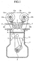
- Fig. 1 is a schematic cross sectional view showing the structure of a general internal combustion engine.
- reference numeral 1 denotes a cylinder of an internal combustion engine
- 2 is a piston which undergoes reciprocal motion in the cylinder 1
- 3 is a crankshaft which is rotated by the reciprocal motion of the piston 2
- 4 is a combustion chamber which combusts and explodes a gaseous mixture
- 5 is an ignition plug which ignites the compressed gaseous mixture in the combustion chamber 4 with a spark
- 6 is an air intake passage which supplies a gaseous mixture to the combustion chamber 4
- 7 is an exhaust passage which exhausts the gases combusted in the combustion chamber 4
- 8 is an intake valve which opens and doses the air intake passage 6
- 9 is an exhaust valve which opens and closes the exhaust passage 7
- 10a is a camshaft near the air intake.
- the air-intake camshaft 10a has a cam 11a which drives the opening and closing of the intake valve 8
- 11b is a camshaft near the exhaust and has a cam 11b which drives the opening and closing of the exhaust valve 9.
- 12a is a timing pulley or a timing sprocket near the air intake which is rotatably fitted and retained on the air-intake camshaft 10a.
- 12b is a timing pulley or a timing sprocket near the exhaust which is rotatably fitted and retained on the exhaust camshaft 11b.
- 13 is a timing chain or a timing belt which links the timing pulley or the timing sprocket 12a, 12b with the crankshaft 3.
- a valve timing regulation device is provided in the air-intake camshaft 11a and the exhaust camshaft 11b of the internal combustion engine.
- Fig. 2 is a cross sectional view in an axial direction of a first conventional valve timing regulation device as disclosed for example in JP-A-10-68306.
- the first conventional valve timing regulation device regulates the opening and closing timing of the exhaust valve 9 in Fig. 1.
- Fig. 2 those components which are the same as or similar to those shown in Fig. 1 are designated by the same reference numerals.
- reference numeral 14 denotes a fixed camshaft sleeve securely fitted with a camshaft 10b near an exhaust (hereafter this will simply be referred to as camshaft).
- the timing pulley 12b near the exhaust is arranged rotatably on the camshaft 10b through the camshaft sleeve 14.
- the camshaft 10b and the camshaft sleeve 14 rotate together.
- the timing pulley 12b rotates relative to the camshaft 10b.
- 12c is a projection for catching the spring thereon, which is integrally formed on one face of the timing pulley 12b and projects therefrom.
- 15 is a spiral spring, an outer radial side end portion of which is hung on the projection 12c and an inner radial side end portion of which is hung on the camshaft sleeve 14.
- the spiral spring 15 urges the rotor 18 (discussed hereafter) in an advancing direction, the urging force is set to be greater than the maximum torque when the internal combustion engine is started.
- 16 is a housing which is fixed by a bolt 17 on the timing rotation body 12b, 16a is an annular partition which is formed in the middle of an inner peripheral surface of the housing 16. An internal section of the housing 16 is partitioned by the partition 16a into a rotor storage chamber 16b on one axial end and a spring storage chamber 16c on the other axial end. The spiral spring 15 is stored in the spring storage chamber 16c.
- the rotor 18 is a rotor which is rotatably stored in the rotor storage chamber 16b of the housing 16.
- the rotor 18 is fixed with an axial bolt 19 to an end portion of the camshaft 10b and is adapted to rotate together with the camshaft 10b.
- the housing 16 and the rotor 18 can rotate relative to one another.
- the 20 is a covering member which covers the open end of the housing 16 and is fixed with a bolt 21to the housing 16.
- Fig. 3 is a cross sectional view of the first conventional valve timing regulation device along the line A-A in Fig. 2.
- reference numeral 22 denotes a plurality of shoes which project from an inner peripheral surface of the housing 16.
- the shoes 22 are integrated with the housing 16, the tips of the shoes 22 are in slide contact with the rotation body of the rotor 18.
- Reference numeral 23 denotes a plurality of vanes which project from an outer peripheral surface of the rotor 18 and extend in a radial direction. These vanes are integrated with the rotor 18, the tips of the vanes 23 are respectively in slide contact with the inner peripheral surface of the housing 16 between the shoes 22.
- An advance hydraulic chamber 24 and a retard hydraulic chamber 25 each having a fan-shaped space is formed between the shoes 22 and the vanes 23.
- a hydraulic oil is supplied from the hydraulic control system (not shown) to the advance hydraulic chamber 24 and the retard hydraulic chamber 25 in accordance with the operation condition of the internal combustion engine.
- the first conventional valve timing regulation device is provided with a lock mechanism (not shown) for locking the rotor 18 at a maximum advance position with respect to the housing 16.
- the lock mechanism includes a stopper which is contained in the rotor 18 to be displaceable in its axial direction and a stopper hole which is formed on a cover member to engage and disengage with the stopper.
- the lock mechanism is also provided with a valve timing regulation mechanism on the air intake side which regulates the opening and closing timing of the intake valve 8 in Fig. 1.
- the lock mechanism of the intake side valve timing regulation device is adapted to lock the rotor at a maximum retard position in an opposite manner to that of the exhaust side valve timing regulation device.
- a rotational force of the crankshaft 3 is transmitted respectively to the intake side camshaft 11a and the exhaust side camshaft 11b through the timing pulleys 12a, 12b by the timing belt 13 during operation of the internal combustion engine.
- the rotor 18 and the housing 16 as shown in Fig. 2 and Fig. 3 are in a lock released state.
- the opening and closing timing of the intake valve 8 and the exhaust valve 9 in Fig. 1 is regulated by the relative rotation of the housing 16 and the rotor 18 due to a pressure differential of the advance side hydraulic chamber 24 and the retard side hydraulic chamber 25 to which a hydraulic oil is supplied from the hydraulic control system in accordance with the operation condition of the internal combustion engine.
- a rotational reaction force in the retarding direction is generated respectively to the intake side camshaft 11a and the exhaust side camshaft 11b shown in Fig. 1.
- the lock position of the air-intake side camshaft 11a is set to a maximum retarded position and the lock position of the exhaust side camshaft 11b is set to a maximum advanced position. Therefore, when the internal combustion engine is stopped, although the intake side camshaft 11a is locked in the maximum retarded position, the exhaust side camshaft 11b tends to rotate in the retarding direction which is the opposite direction to the locked position.
- the exhaust side camshaft 11b is urged in the advancing direction by the spiral spring 15 through the rotor 18 which rotates together with the exhaust side camshaft 11b. Therefore, the exhaust side camshaft 11b is not affected by the rotational reaction force when the internal combustion engine is stopped, the rotor 18 is locked in the housing 16 by the locking mechanism at the maximum advanced position. In such a way, the housing 16 and the rotor 18 can rotate together when the internal combustion engine is started.
- the first conventional valve timing regulation device is constructed above, in order to allow assembly of the spiral spring 15, it is necessary to integrate the projection 12c on the stem of the timing pulley 12b and to form the camshaft sleeve 14 as a separate component from the camshaft 10b. Furthermore, it is necessary to form a spring storage chamber 16c separated from the rotor storage chamber 16b by the partition 16a in the housing 16 in order to maintain an assembly space for the spiral spring 15. Therefore, problems related to structural complexity and increases in costs have arisen. In particular, when assembling the spiral spring 15, one end is attached to the projection 12c and the other end is attached to the camshaft sleeve 14 while the spiral spring 15 is twisted.
- Fig. 4 is a cross sectional view along an axial direction showing the structure of a second conventional valve timing regulation device as disclosed for example in JP-A-10-68306.
- Fig. 5 is a cross sectional view of the second conventional valve timing regulation device along the line B-B in Fig. 4.
- reference numeral 26 denotes a rear plate having a boss portion which is rotatably fitted on an outer periphery of a camshaft sleeve 14. The rear plate 26 is fixed integrally with the timing pulley 12b, the housing 16 and the cover member 20 by a bolt 17a.
- 26a is a projection for catching the spring thereon, which projects from a lateral face of the flange of the rear plate 26.
- the projection 26a is integrated with the flange of the rear plate 26.
- 27 is a torsion spring which urges the camshaft 10b in its advancing direction, the torsion spring 27 is inserted into a ring-shaped space formed between an outer peripheral surface of the camshaft sleeve 14 and an inner peripheral surface of the boss portion of the rear plate 26.
- One end of the torsion spring 27 is attached to the camshaft sleeve 14 and the other end is attached to the projection 26a. Since the operation of this second conventional example is the same as that of the first conventional example, further description will be omitted.
- the second conventional valve timing regulation device Since the second conventional valve timing regulation device is constructed as above, it is necessary to form the rear plate 26 separately as an assembly component for the torsion spring 27. As a result, the number of components and the number of component assembly steps are increased, thereby to increase the cost. Furthermore, assembly of the torsion spring 27 is extremely complicated. In particular, since the assembled torsion spring 27 is in slide contact with the outer peripheral surface of the camshaft sleeve 14 and the inner peripheral surface of the boss portion of the rear plate 26, the problem has arisen that the sliding resistance of the torsion spring 27 is increased, thereby to affect the opening and closing timing of the valve.
- Fig. 6 is a cross sectional view along an axial direction of a third conventional valve timing regulation device as disclosed for example in JP-A-10-68306.
- Those components which are the same as or similar to those in Fig. 1 to Fig. 5 are denoted by the same reference numerals and additional description will be omitted.
- reference numeral 22a denotes a shoe side concavity which is provided on a peripheral end face towards an advancing direction in each shoe 22 of the housing 16.
- 23a is a vane side concavity which is provided on a peripheral end face towards a retarding direction in each vane 23 of the rotor 18.
- the rotor 18 is a coil spring both ends of which are directly fitted into the shoe side concavity 22a and the vane side concavity 23a.
- the spring 28 urges the rotor 18 in the advancing direction with respect to the housing 16.
- the rotor 18 is displaced in a rotational direction to a maximum advanced position by the urging force of the spring 28 when the internal combustion engine is stopped, and the rotor 18 is locked with respect to the housing 16 at the maximum advanced position.
- the third conventional valve timing regulation device Since the third conventional valve timing regulation device is constructed as above, it is necessary to fit both ends of the spring 28 directly into the shoe side concavity 22a and the vane side concavity 23a in the advancing hydraulic chamber 24 from a peripheral direction while compressing the spring 28. Thus, the problem has arisen that there is a high probability of reductions in assembly productivity of the spring 28 due to the generation of a curvature or a compressive reaction force of the spring 28 when fitting the spring.
- both ends of the spring 28 are directly fitted to the shoe side concavity 22a and the vane side concavity 23b, there is a high probability of wear being caused in the fitting portion of the spring 28 by the friction between the spring 28 and the inner walls of the shoe side concavity 22a and the vane side concavity 23b. Furthermore, the problem has arisen that there is a high probability of generating a positional deviation of the spring, thereby causing detachment of the spring 28 from the shoe side concavity 22a and/or the vane side concavity 23b or causing the wear in contact with the covering components in the axial direction which constitute the hydraulic chamber.
- the present invention is proposed to solve the above problems and has the object of providing a valve timing regulation device which can improve assembly productivity of the rotor urging member for urging the rotor in a direction opposite to the rotational reactive force generated on the camshaft when the internal combustion engine is stopped, and which can prevent wear of the rotor urging members.
- valve timing regulation device which allows simple and well-balanced assembly of the rotor urging member so that the rotor in the housing does not undergo a positional deviation in an axial or radial direction, thereby to improve both of the assembly productivity and the assembly accuracy and to simplify the component structure.
- valve timing regulation device which can ensure retention of the holder members, which support both ends of the rotor urging member, on the vane of the rotor and the shoe of the housing.
- valve timing regulation device which allows simple formation of the holder members.
- valve timing regulation device which enables the rotor urging member to display a buffering function by the holder members.
- the present invention has the object of providing a valve timing regulation device which allows mass production of the holder member having sufficient mechanical strength, and allows cost reductions and improvements in productivity.
- the present invention has the object of providing a valve timing regulation device which allows simple assembly of a plurality of rotor urging members, which is united with the holder member, into the same hydraulic chamber, and which allows further improvements to assembly accuracy without entanglement of the plurality of rotor urging members.
- the present invention has the object of providing a valve timing regulation device, which ensures sufficient mechanical strength of the shoes and the vanes to which the rotor urging member is attached.
- the present invention has the object of providing a valve timing regulation device, which allows further simplification in the assembly of the holder members united with the rotor urging member.
- the present invention has the object of providing a valve timing regulation device, which allows downsizing the device by disposition of the rotor urging member in the advancing hydraulic chamber.
- the present invention has the object of providing a valve timing regulation device which allows simple attachment of the holder members, which are formed as a unit together with the rotor urging member, to the vanes and the shoes, and allows improvement of the reliability of the device by preventing the holder members from detaching from the shoes and the vanes.
- a valve timing regulation device including: a camshaft which drives the opening and dosing of valves in an internal combustion engine; a housing which has a plurality of shoes on an inner peripheral face, the housing being arranged to rotate freely on the camshaft and rotated with the output of the internal combustion engine; a rotor having a plurality of vanes which define a retarding hydraulic chamber and an advancing hydraulic chamber in cooperation with the wall surfaces of the shoes directed to a circumferential direction, the rotor being stored in the housing to rotate relative to the housing and coupled to the camshaft; and a lock means which is operated by a mechanical urging force and restricts the relative rotation of the rotor and the housing, the lock means releasing the restriction by operation of a hydraulic pressure in a direction against the mechanical urging force, the valve timing regulation device further comprising: a rotor urging member disposed between the wall surfaces of the shoes and vanes directed to the circumferential direction for urging the rotor in a rotational direction towards
- valve timing regulation device since the ends of the rotor urging member are supported on the wall surfaces of the shoe of the housing and the wall surfaces of the vane of the rotor through the holder members, it is possible to prevent wear of the rotor urging member due to friction with the walls of the shoes and vanes. Further, since a unit of the rotor urging member and the holder members is attached utilizing the hydraulic chambers which is formed between the shoes and the vanes, it is not required to provide a separate space to allow attachment of this unit, and thus, it is possible to downsize the valve timing regulation device and simplify its structure.
- the valve timing regulation device of the present invention may be adapted so that an even number groups of advancing hydraulic chambers and retarding hydraulic chambers are formed between the wall surfaces of the vanes and the shoes, the rotor urging member is arranged in a pair of the advancing hydraulic chambers situated in an axial symmetry position of the rotor, and both ends of the rotor urging member are supported by the pair of holder members mounted on the wall surfaces of the vane and shoe which are disposed on both sides of the advancing hydraulic chamber to sandwich the rotor urging member.
- valve timing regulation device since a unit of the rotor urging member and the holder members disposed on both ends thereof is attached only in the advancing hydraulic chambers arranged in an axial symmetry position of the rotor, it is possible to reduce the number of the holder members and the rotor urging members to be used, and to improve balance of the urging force on the rotor. As a result, it is possible to suppress entanglement and inclination of the rotor.
- a holder engagement portion for fitting the holder member may be formed on the wall surfaces of the vane and the shoe directed toward the circumferential direction.
- valve timing regulation device allows simple assembly of the rotor urging member by merely fitting the holder members, which is united with the rotor urging member, into the holder engagement portions of the vane and the shoe. This allows improvements in assembly productivity and also ensures support of the holder members disposed on both end portions of the rotor urging member.
- the holder members may be integrally formed with a resin material to have an engagement projection or an engagement hole which is fitted with the end portion of the rotor urging member.
- the holder member is formed from an integrated resin component, it is possible to improve the productivity and reduce the cost. Furthermore, the holder members and the rotor urging member can be easily assembled as a unit by merely fitting both ends of the rotor urging member with the engagement hole or the engagement projection of the holder members.
- the holder member may be integrally formed with a resilient member such as hard rubber and have an engagement hole or an engagement projection enabling fitting of both ends of the rotor urging member.
- the holder member is formed with an integrated component of the resilient member such as hard rubber, it is possible to improve the productivity and reduce the cost. Further, the holder members and the rotor urging member can be easily assembled as a unit by merely fitting both ends of the rotor urging member into the engagement hole or the engagement projection of the holder members. Furthermore, it is possible to display a buffer function of the rotor urging member sufficiently by the provision of the holder members.
- the holder members may be formed with a pressed sheet metal member.
- valve timing regulation device it is possible to effect mass production of the holder members by a pressing process of the metal plate. Furthermore, it is possible to ensure a sufficient mechanical strength for the holder members.
- the holder members which have an engagement hole or an engagement projection to fit with the end portions of the rotor urging member, may be integrally formed by a molding process such as casting or forging of a metallic material.
- the holder member is formed as a metallic molded component by a process such as forging or casting of the metallic material, it is possible to improve the productivity and reduce the cost. Furthermore, it is possible to easily assemble the rotor urging member and the holder members as a unit by merely fitting both ends of the rotor urging member into the engagement hole or the engagement projection of the holder members.
- the rotor urging member may be at least two coil springs, both ends of which are supported by a pair of holder members and which are stored in the same advancing hydraulic chamber, the coil springs having coil wire diameter different from each other.
- the coil springs which are arranged in parallel and supported at both ends by a pair of holder members, have different size in diameter of coil wire from each other, and thus the coil springs are also different in coil pitch (wire-to-wire distance) from each other.
- the parallel springs which are assembled as a unit together with the holder members, undergo a bending compression, the springs do not become entangled. Therefore, it is possible to further improve assembly accuracy by suppression of meshing or inclination of the rotor as a result of such entangling.
- the rotor urging member which is supported at both ends by a pair of holder members and is stored in the same advancing hydraulic chamber may be constituted by at least two coil springs with different number of turns.
- the valve timing regulation device may be adapted so that the peripheral lengths of the shoes and vanes to be disposed on both sides of the advancing hydraulic chambers which store the rotor urging member, is longer than those of the shoes and vanes to be disposed on both sides of the other advancing hydraulic chambers which do not store the rotor urging member.
- the holder engagement portion may be formed as axial grooves, which allow insertion of the holder members from one axial end.
- valve timing regulation device when mounting the unit of the rotor urging member and the holder members, it is possible to attach the unit of the rotor urging member and the holder members efficiently and easily by merely inserting the holder members from one axial end into the axial grooves formed on the wall surfaces of the shoe and the vane oriented to the circumferential direction. Thus, assembly productivity is further improved. Further, as described above, since the holder members are attached by direct insertion into the axial grooves of the shoe and the vane, a separate component for assembly is not necessary. Thus, the structure can be simplified and cost reductions can be realized. Furthermore, the valve timing regulation device can be downsized.
- the holder engagement portion may be formed as holes which are opened in the wall surfaces of the shoe and the vane.
- valve timing regulation device when mounting the unit of the rotor urging member and the holder members, it is possible to attach the unit of the rotor urging member and the holder members efficiently and easily by fittingly inserting the holder members into the holes opened on the wall surfaces of the shoe and the vane oriented to the circumferential direction. Thus, assembly productivity is further improved. Further, since a separate component is not required for mounting the holder members as this is in the form of the holes provided on the wall surfaces of the shoe and vane, the structure can be simplified by the reduction in component number and cost reductions can be realized. Furthermore, the valve timing regulation device can be downsized.
- the valve timing regulation device may be adapted so that the holder engagement portion is formed as axial grooves which allow insertion of the holder members from one axial end, and a holder detachment prevention means is provided on at least one of the axial grooves and the holder members, the holder detachment prevention means limiting the displacement of the holder members in the axial grooves with respect to a rotation direction of the device.
- valve timing regulation device even if vibration or an unlikely unforeseen event occurs, detachment of the holder members in the rotation direction of the device is not possible and accurate operation of the device can be ensured.
- the holder detachment prevention means may be formed by a tapering face provided on a lateral wall surface of the holder engagement groove to gradually narrow the groove width of the holder engagement groove towards an opened end of the groove, and an another tapering face provided on a lateral wall surface of the holder member in alignment with the tapering face.
- the holder detachment prevention means can be provided easily by merely forming the lateral wall surfaces of the holder members and the holder engagement grooves in a tapering shape. Thus, even if vibration or an unlikely unforeseen event occurs, detachment of the holder members in the rotation direction of the device is not possible and accurate operation of the device can be ensured.
- the holder detachment prevention means may be formed as a catch for preventing detachment which engages with the holder member disposed in the holder engagement groove, the catch being arranged in an opened end of the respective holder engagement grooves of the shoe and the vane.
- the holder detachment prevention means can be provided easily by merely forming the catch in the opened end of the respective holder engagement grooves of the shoe and the vane.
- the holder detachment prevention means can be provided easily by merely forming the catch in the opened end of the respective holder engagement grooves of the shoe and the vane.
- the holder detachment prevention means may be formed by engagement concavities arranged on one of the holder members and the holder engagement grooves of the shoe and the vane, and engagement protrusions arranged on the other of the holder members and the holder engagement grooves, the engagement concavity and the engagement protrusion being engaged with each other.
- the holder detachment prevention means can be provided easily by merely forming the engagement concavities on one of the holder members and the holder engagement grooves and the engagement protrusions on the other of the holder members and the holder engagement grooves.
- the holder detachment prevention means may be formed by key grooves formed on both of the holder members and the holder engagement grooves of the shoe and vane, and a key member inserted into both key grooves.
- valve timing regulation device it is possible to fix the holder members in the holder engagement grooves by merely inserting the key member into both key grooves of the holder member and the holder engagement groove. Thus, even if vibration or an unlikely unexpected event occurs, detachment of the holder members in the rotation direction of the device is not possible and accurate operation of the device can be ensured.
- Fig. 1 is a schematic cross sectional view showing the structure of a general internal combustion engine.
- Fig. 2 is a cross sectional view along an axial direction of a first conventional valve timing regulation device.
- Fig. 3 is a cross sectional view along the line A-A of Fig. 2.
- Fig. 4 is a cross sectional view along an axial direction of a second conventional valve timing regulation device.
- Fig. 5 is a cross sectional view along the line B-B of Fig. 4.
- Fig. 6 is a cross sectional view along an axial direction of a third conventional valve timing regulation device.
- Fig. 7 is a cross sectional view along an axial direction of a valve timing regulation device according to a first embodiment of the present invention.
- Fig. 8 is a cross sectional view along the line C-C of Fig. 7.
- Fig. 9 is a cross sectional view along the line D-D of Fig. 8.
- Fig. 10 is a cross sectional view showing a unit of the springs being a rotor urging member as shown in Fig.8 and Fig. 9 and the holder members therefor.
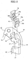
- Fig. 11 is an exploded perspective view showing the components of the valve timing regulation device according to the first embodiment of the present invention.
- Fig. 12 is a cross sectional view in a radial direction of a valve timing regulation device according to a second embodiment of the present invention.
- Fig. 13 is a cross sectional view in a radial direction of a valve timing regulation device according to a third embodiment of the present invention.
- Fig. 14 is a cross sectional view showing a unit of the springs for urging a rotor and the holder members according to a fourth embodiment of the present invention.
- Fig. 15 is a cross sectional view showing a unit of the springs for urging a rotor and the holder members therefor according to a fifth embodiment of the present invention.
- Fig. 16 is a perspective view showing a pair of holder members according to a seventh embodiment of the present invention.
- Fig. 17 is a cross sectional view showing a unit of the springs for urging a rotor and the holder members therefor according to a ninth embodiment of the present invention.
- Fig. 18 is a cross sectional view showing a unit of the springs for urging a rotor and the holder members according to a tenth embodiment of the present invention.
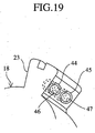
- Fig. 19 is a partial perspective view showing the rotor of a valve timing regulation device according to an eleventh embodiment of the present invention.
- Fig. 20 is a cross sectional view showing the components of a valve timing regulation device according to a twelfth embodiment of the present invention.
- Fig. 21 is an exploded perspective view of Fig. 20.
- Fig. 22 is a cross sectional view showing the components of a valve timing regulation device according to a thirteenth embodiment of the present invention.
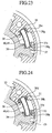
- Fig. 23 is a cross sectional view showing the components of a valve timing regulation device according to a fourteenth embodiment of the present invention.
- Fig. 24 is a cross sectional view showing the components of a valve timing regulation device according to a fifteenth embodiment of the present invention.
- Fig. 7 is a cross sectional view along an axial direction of a valve timing regulation device according to a first embodiment of the present invention. Those components which are the same as or similar to components in Fig. 1 to Fig. 6 are designated by the same reference numerals and additional description will be omitted.
- reference numeral 29 denotes a pin hole which is formed in an axial direction on one vane 23 of the rotor 18.
- 30 is a lock pin which is inserted into the pin hole 29 so as to slide therein.
- 31 is a lock hole which is provided in a timing sprocket or a timing pulley 12b (hereafter timing rotation body).
- the lock hole 31 is detachably fitted to the lock pin 30 at a maximum advanced position of the rotor 18 with respect to the housing 16 and is composed of a concave hole opening on a sliding face of the timing rotation body 12b which comes into slide contact with the rotor 18.
- 32 is a spring as a mechanical urging means which urges the lock pin 30 in an engaging direction with the lock hole 31.
- the spring 32 is stored in the pin hole 29.
- the lock hole 31 is connected to the oil passage of the hydraulic control system, a hydraulic oil is applied to the head of the lock pin from the oil passage when the internal combustion engine is in operation.
- a hydraulic oil is applied to the head of the lock pin from the oil passage when the internal combustion engine is in operation.
- the applied hydraulic pressure to the lock pin 30 becomes lower than the urging force of the spring 32 in response to the operational condition of the internal combustion engine, the lock pin 30 is fitted into the lock hole 31 due to the urging force of the spring 32, the housing 16 and the rotor 18 are locked to rotate together.
- the applied hydraulic pressure becomes larger than the urging force of the spring 32, the lock pin 30 is detached from the lock hole 31 by the applied hydraulic pressure and the locking is released.
- the lock pin 30 locks the rotor 18 at a maximum advanced position with respect to the housing 16 by the fitting of the lock pin 30 into the lock hole 31 due to the action of the urging force of the spring 32 urging the lock pin 30.
- the lock pin 30 is detached from the lock hole 31 by the action of the hydraulic control pressure (the applied hydraulic pressure) in a direction against the urging force of the spring 32, thereby to release the locking.
- the lock pin 30, the lock hole 31 and the spring 32 constitute a locking means for the rotor 18 with respect to the housing 16.
- the atmosphere opening passage 33 is an opening passage to the atmosphere (hereafter atmosphere opening passage) provided in the rotor 18.
- the atmosphere opening passage 33 opens the side storing the spring 32 in the pin hole 29 to the atmosphere.
- the atmosphere opening passage 33 also serves as an air hole and a drain passage.
- Fig. 8 is a cross sectional view along the line C-C of Fig. 7.
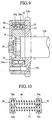
- Fig. 9 is a cross sectional view along the line D-D of Fig. 8.
- reference numeral 34 denotes a tip seal provided on the tip of each shoe 22 of the housing 16 to be slidable in the radial direction.
- 34a is a back spring (refer to Fig. 7 and Fig. 9) which urges the tip seal 34 in a direction of sliding contact with an outer peripheral surface of the body portion of the rotor 18.
- 35 is a tip seal provided on the tip of each vane 18 of the rotor 18 to slide in the radial direction.
- the tip seal 35 has a back spring (not shown) in the same way as the tip seal 34 to the shoes 22 and the tip seal 35 is in slide contact with an inner peripheral surface of the housing 16 by the urging force of the back spring.
- reference numeral 36 denotes a concave groove (hereafter shoe groove) provided on a wall surface of each shoe 22 situated on a side of the advancing hydraulic chamber 24.
- 37 is a concave groove (hereafter vane groove) provided on a wall surface of each vane 23 situated on the side of the advancing hydraulic chamber 24.
- the shoe grooves 36 and vane grooves 37 serve as a holder engagement section which engages with the holder members 38, 39 (described below) for retaining the spring.
- the shoe grooves 36 and vane grooves 37 are formed on the wall surface of each shoe 22 and each vane 23 and run the full axial length thereof. Thus, both ends of the vane groove 37 and the shoe groove 36 are opened on both end faces in the axial direction of each shoe 22 and each vane 23.
- Reference numerals 38, 39 denote a pair of holder members for retaining the spring, which are fitted respectively into the shoe groove 36 and the vane groove 37.
- 40, 41 are coil springs (hereafter simply referred to as spring), both ends of which are fitted into the holder members 38, 39 and stored in each advancing hydraulic chamber 24.
- the springs 40, 41 are retained in a compressed state between the shoe 22 and vane 23 which define the advancing hydraulic chamber 24.
- the springs 40, 41 serve as a rotor urging member which urges the rotor 18 toward the advancing direction with respect to the housing 16 by its elastic force.
- Fig. 10 is a cross sectional view of the unit constituted by the springs 40, 41 as a rotor urging member and the holder members 38, 39 therefor in Fig.8 and Fig. 9.
- the holder members 38, 39 are fitted into the shoe groove 36 and the vane groove 37, and are integrally formed by a resinous material in a rectangular parallelepiped shape with approximately the same length as the axial length of the shoe groove 36 and the vane groove 37.
- the holder members 38, 39 each have two engagement holes 38a, 38b and 39a, 39b into which both ends of the springs 40, 41 are fitted.
- the engagement holes 38a, 38b and 39a, 39b are formed by cylindrical holes.
- Fig. 11 is a partial perspective view showing the assembly process of the springs 40, 41.
- an assembly unit comprising the right and left pair of holder members 38, 39 and the double springs 40, 41 is formed by fitting both ends of the springs 40, 41 being fittingly inserted into the engagement holes 38a, 38b and 39a, 39b of the pair of holder members 38, 39 respectively, the unit of the holder members 38, 39 and the springs 40, 41 is assembled.
- valve timing regulation device After assembly, the valve timing regulation device is assembled by fixing a covering member 20 and a timing rotation body 12b to both axial ends of the housing 16 with a bolt 17a as shown in Fig. 7 and Fig. 9.
- the valve timing regulation device is attached to the camshaft 10b and the rotor 18 is fixed with an axial bolt 19 to the camshaft 10b. In this manner, the valve timing regulation device is mounted on the engine.
- valve timing regulation device Next, the operation of the valve timing regulation device will be described below.
- the rotor 18 does not rotate in the retarding direction even when the internal combustion engine is stopped and the rotational reactive force is generated to the camshaft 10b. Namely, rotation of the rotor 18 up to a maximum advanced position is ensured by the elastic force of the springs 40, 41, the lock pin 30 becomes faced with the lock hole 31 at the maximum advanced position. As a result, the lock pin 30 is inserted into the lock hole 31 by the urging force of the rear spring 32, thereby to lock the rotor 18 and the housing 16.
- both ends of each of the springs 40, 41 which urges the rotor 18 in the housing 16 toward an advancing direction, are supported through the holder members 38, 39 on the wall surfaces of the shoe 22 and vane 23.
- both ends of the springs 40, 41 do not undergo friction with the wall portion of the shoe 22 and the vane 23.
- the advantageous effect is obtained that frictional wear of the springs 40, 41 is prevented.
- the assembly productivity of the springs 40, 41 is improved.
- the vane 23 of the rotor 18 is not inclined by the torsion reactive force which thus improves the assembly accuracy of the springs.
- the springs 40, 41 are stored in the advancing hydraulic chamber 24 as described above.
- a separate spring storage chamber 16c which is partitioned from the rotor storage chamber 16b by a partition 16a projecting from the inner periphery of the housing 16.
- the structure of the device can be simplified as the projection 12c as shown in Fig. 2 and the rear plate 26 as shown in Fig. 4 are no longer required. Thus, it is possible to reduce the costs and to downsize the valve timing regulation device.
- a shoe groove 36 and a vane groove 37 are formed over the full axial length on the wall surfaces of the shoe 22 and the vane 23 which are situated on both sides of the advancing hydraulic chamber 24, and the holder members 38, 39 for the springs 40, 41 are engaged with the shoe groove 36 and the vane groove 37.
- the holder members 38, 39 are provided with engagement holes 38a, 38b, 39a, 39b each having a concave shaped cross section, into which the ends of the springs 40, 41 are respectively fitted.
- the springs 40, 41 can be retained in parallel by the holder members 38, 39 situated on both sides thereof and thus formed into a unit.
- the slide insertion of the holder members 38, 39 into the shoe groove 36 and the vane groove 37 from one axial end it is possible to simply mount the two parallel springs 40, 41 in the engine.
- the holder members 38, 39 are pressed into the shoe groove 36 and the vane groove 37 with the repulsive force of the springs 40, 41, both axial ends of the shoe groove 36 and the vane groove 37 are covered by the covering member 20 and the timing rotation body 12b. Therefore, the holder members 38, 39 can not be detached from the shoe groove 36 and the vane groove 37, it is possible to certainly and securely mount the two springs 40, 41 in parallel to each other at a fixed mounting position. As a result, assembly accuracy can be improved.
- the holder members 38, 39 are formed from an integrated component of resinous material, it is possible to improve the productivity, thereby reducing the cost.
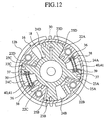
- Fig. 12 is a cross sectional view in a radial direction of a valve timing regulation device according to a second embodiment of the present invention.
- Those components which are the same as or similar to components in Fig. 1 to Fig. 11 are designated by the same reference numerals and additional description will be omitted.
- reference numerals 22A-22D denote an even number (4 in the figure) of shoes which are integrated with the housing 16 and project from an inner peripheral surface of the housing 16.
- 23A-23D denote an even number (the same number of shoes 22A-22D) of vanes which are integrated with the rotor 18 and project from an outer peripheral surface of the rotation body of the rotor 18.
- an even number in the figure, there are four groups) of advancing hydraulic chambers 24A-24D and retarding hydraulic chambers 25A-25D are formed by the shoes 22A-22D and the vanes 23A-23D.
- the advancing hydraulic chambers 24A-24D are adapted so that a pair of advancing hydraulic chambers 24A, 24C are arranged in an axial symmetry position to each other with respect to an axis of the rotor 18 (the camshaft 10b in Fig. 7 and Fig. 9) and a unit of the springs 40, 41 and the holder members 38, 39 is attached only in the pair of the advancing hydraulic chambers 24A, 24C.
- the shoe groove 36 and the vane groove 37 are formed only on the wall surfaces of the shoes 22A, 22C and vanes 23A, 23C which are situated on both sides of the advancing hydraulic chambers 24A, 24C disposed in the axial symmetry position.
- the unit of the springs 40, 41 and holder members 38, 39 is attached in each advancing hydraulic chamber 24.
- the unit of the springs 40, 41 and the holder members 38, 39 is attached only in a pair of advancing hydraulic chambers 24A, 24C which are disposed in an axial symmetry position with respect to the rotor 18.
- the holder members 38, 39 disposed on both ends of the springs 40, 41 are attached into the shoe groove 36 and vane groove 37 by sliding insertion from one axial end thereof.
- the units of the springs 40, 41 and the holder members 38, 39 are arranged only into the pair of advancing hydraulic chambers 24A, 24C which are disposed in the axial symmetry position with respect to a central axis of the rotor 18, it is possible to reduce the number of process steps for the shoe groove 36 and the vane groove 37. It is also possible to reduce the number of the springs 40, 41 and the holder members 38, 39 used and therefore to reduce the cost. Moreover, as described above, since two units of the springs 40, 41 and the holder members 38, 39 are disposed in the axial symmetry position with respect to the rotor 18, it is possible to mount the two spring units in a well-balanced manner. As a result, it is possible to suppress inclination and entanglement of the rotor 18 in the housing 16.
- Fig. 13 is a cross sectional view in a radial direction of a valve timing regulation device according to a third embodiment of the present invention. Those components which are the same as or similar to components in Fig. 12 are designated by the same reference numerals and additional description will be omitted.
- the unit of the holder members 38, 39 and the springs 40, 41 is arranged and assembled only in the advancing hydraulic chambers 24A, 24C which are situated in an axial symmetry position about the rotor 18 in the same manner as the second embodiment.
- the respective peripheral length of the shoes 22A, 22C and the vanes 23A, 23C forming the respective advancing hydraulic chambers 24A, 24C is set so that it is longer than the respective peripheral length of the shoes 22B, 22D and vanes 23B, 23D forming the respective advancing hydraulic chambers 24B, 24D in which the unit of the holder members 38, 39 and the springs 40, 41 is not mounted.
- the respective peripheral length of the shoes 22A, 22C and vanes 23A, 23C forming the axial symmetry advancing hydraulic chambers 24A, 24C, in which the unit of the holder members 38, 39 and the springs 40, 41 is mounted is set so that it is longer than the respective peripheral length of the shoes 22B, 22D and vanes 23B, 23D forming other advancing hydraulic chambers 24B, 24D in which the unit of the holder members 38, 39 and the springs 40, 41 is not mounted.
- Fig. 14 is a cross sectional view of the unit constituted by the holder members and the springs, which acts as a rotor urging member, according to a fourth embodiment of the present invention.
- Those components which are the same as or similar to those in Fig. 10 are denoted by the same reference numerals and additional description will be omitted.
- reference numerals 38c, 39c denote tapering mouths formed by beveling the mouth edges of the engagement holes 38a, 38b and 39a, 39b of the right and left holder members 38, 39.
- the mouth edges of the engagement holes 38a, 38b, 39a, 39b of the holder members 38, 39 are formed as tapering mouths 38c, 39c, it is possible to fit both ends of the springs 40, 41 easily into the engagement holes 38a, 38b, 39a, 39b of the holder members 38, 39. As a result, it is possible to easily assemble a unit of the pair of holder members 38, 39 and the two springs 40, 41.
- Fig. 15 is a cross sectional view of the unit constituted by the springs and the holder members as a rotor urging member according to a fifth embodiment of the present invention.
- reference numerals 38A, 39A denote a face plate portion of each holder member 38, 39.
- 38d, 38e and 39d, 39e are engagement projections for engaging the spring which are integrally formed on one face of each face plate portion 38A, 39A and project therefrom.
- the holder members 38, 39 are provided with the engagement holes 38a, 38b, 39a, 39b which retain both ends of the springs 40, 41, each of the holder members 38, 39 is integrally formed by a resinous material, and both ends of the springs 40, 41 are supported by using the holder members 38, 39.
- the holder members 38, 39 are provided with the engagement projections 38d, 38e, 39d, 39e instead of the engagement holes 38a, 38b, 39a, 39b, each of the holder members 38, 39 is integrally formed by a resinous material, and both ends of the springs 40, 41 are supported by use of the holder members 38, 39.
- the fifth embodiment it is possible to easily assemble a unit of the holder members 38, 39 and the springs 40, 41 by engaging both ends of the springs 40, 41 with the engagement projections 38d, 38e, 39d, 39e of the holder members 38, 39 and to attach the unit in the shoe groove 36 and the vane groove 37. Namely, it is possible to obtain the same advantageous effects as the first to fourth embodiments.
- each holder member 38, 39 which has engagement holes 38a, 38b, 39a, 39b or engagement projections 38d, 38e, 39d, 39e is integrally formed by a resinous material.
- each holder member 38, 39 is integrally formed by a hard resilient material such as a hard rubber or the like.
- the holder members 38, 39 are formed by the hard resilient material, it is possible to display a buffering function of the springs 40, 41 by the holder members 38, 39.
- Fig. 16 is a perspective view showing a pair of holder members according to a seventh embodiment of the present invention.
- reference numerals 42, 43 denote a pair of holder members formed by a pressed sheet metal.
- Each holder member 42, 43 is integrally formed in a shape with a pair of concavities 42a, 42b and 43a, 43b which are adjacent to each other and fitted with both ends of the springs 40, 41 as shown in the first to fifth embodiments.
- each holder member 42, 43 is integrally formed from a sheet metal in a shape with a pair of concavities 42a, 42b and 43a, 43b which are disposed adjacent to each other and into which the ends of the springs 40, 41 is respectively fitted.
- a pair of concavities 42a, 42b and 43a, 43b which are disposed adjacent to each other and into which the ends of the springs 40, 41 is respectively fitted.
- each holder member 38, 39 is integrally formed by a molding process such as metal casting or forging.
- a valve timing regulation device as above allows mass production of the holder members 38, 39 with a sufficient mechanical strength by a molding process on a metallic material. Thus, the productivity can be improved, thereby reducing the cost. Furthermore, it is possible to provide the holder members 38, 39 and the springs 40, 41 as a unit by simply fitting both ends of the springs 40, 41 with the engagement holes 38a, 38b, 39a, 39b or engagement projections 38d, 38e, 39d, 39e.
- Fig. 17 is a cross sectional view showing a unit of the springs as a rotor urging member and the holder members therefor according to a ninth embodiment of the present invention.
- Those components which are the same as or similar to those in Fig. 10 and Fig. 14 are denoted by the same reference numerals and additional description will be omitted.
- the springs 40, 41 are adapted so that one spring 40 is formed by a large diameter coil wire and the other spring 41 is formed by a small diameter coil wire. Namely, the coil wires of the springs 40, 41 have different sizes in diameter. However, the springs 40,41 have the same length.
- the springs 40, 41 disposed in parallel and supported at both ends by the pair of holder members 38, 39 have the different coil wire in diameter from each other, a coil pitch (wire to wire distance of the coil) in one spring 40 is also different from that in the other spring 41.
- the springs 40, 41 do not become mutually entangled even in the unlikely event that a bending compression is applied to the parallel springs 40,41 which are provided as a unit with the holder members 38, 39.
- Fig. 18 is a cross sectional view showing a unit of the springs for urging a rotor and the holder members according to a tenth embodiment of the present invention.
- Those components which are the same as or similar to those in Fig. 17 are denoted by the same reference numerals and additional description will be omitted.
- double springs 40, 41 are provided with the same length in a parallel unit with the pair of holder members 38, 39 in the same manner as the first to third embodiments above, and the number of turns in one spring 40 is greater than that in the other spring 41. Namely, the springs 40, 41 are different in the number of turns from each other.
- the springs 40, 41 do not become mutually entangled even in the unlikely event that a bending compression is applied to the parallel springs 40, 41 provided as a unit with the holder members 38, 39.
- it is possible to suppress inclination or meshing of the rotor 18 generated as a result of the entanglement, thereby to further improve assembly accuracy.
- Fig. 19 is a partial perspective view showing the rotor of a valve timing regulation device according to an eleventh embodiment of the present invention.
- Those components which are the same as or similar to those in Fig. 8, Fig. 11 and Fig. 12 are denoted by the same reference numerals and additional description will be omitted.
- reference numerals 44, 45 denote holes for engaging the holder members, which are opened on a wall surface of the vane 23 situated on a side of the advancing hydraulic chambers 24.
- 46, 47 are cylindrical holder members which are engaged with the holes 44, 45.
- the holder members 46, 47 are formed from a resilient material such as hard rubber or resinous material and fitted with one end of the springs 40, 41 as described with reference to the first to tenth embodiments.
- Holes which open toward the advancing hydraulic chambers 24 are also provided on the side wall surface of the shoe 22 of the housing 16 which is situated on a side of the advancing hydraulic chambers 24 storing the springs 40, 41 as shown in Fig. 8, Fig. 11 and Fig. 12.
- the holder members 46, 47 are engaged with the holes provided on the wall surface of the shoe 22, and the other end of the springs 40, 41 is engaged with the holder members.
- holes 44, 45 are provided on the respective wall surfaces of the shoe 22 and the vane 23 situated on both sides of the advancing hydraulic chamber storing the springs 40, 41, the cylindrical holder members 46, 47 are engaged with the holes 44, 45.
- Fig. 20 is a cross sectional view showing the components of a valve timing regulation device according to a twelfth embodiment of the present invention.
- Fig. 21 is an exploded perspective view of Fig. 20.
- Those components which are the same as or similar to those in Fig. 8 to Fig. 14, Fig. 17 and Fig. 18 are denoted by the same reference numerals and additional description will be omitted.
- reference numeral 36a denotes a tapering face which is formed on both inner wall surfaces of the concave shoe groove (holder engagement groove) 36.
- the taper face 36a is formed so that the groove width of the shoe groove 36 is gradually narrowed towards the open end.
- 37a is a tapering face formed on both inner wall surfaces of the concave vane groove (holder engagement groove) 37.
- the tapering face 37a is formed so that the groove width of the vane groove 37 is gradually narrowed towards the open end.
- 38f, 39f are tapering surfaces which are formed respectively on both wall surfaces of the holder members 38, 39.
- the holder members 38, 39 are formed in a reversed wedge shape by the tapering faces 38f, 39f.
- the tapering faces 36a, 37a of the shoe groove 36 and the vane groove 37 are formed with approximately the same tapering angle as the tapering faces 38f, 39f of the holder member 38, 39.
- the tapering faces 36a, 37a of the shoe groove 36 and the vane groove 37 is adapted to fit with the tapering face 38f, 39f of the holder member 38, 39 when inserting the holder member 38, 39 into the shoe groove 36 and the vane groove 37.
- the holder members 36, 37 are wedged in the shoe groove 36 and the vane groove 37 by alignment of the tapering faces 38f, 39f of the holder members 38, 39 with the tapering faces 36a, 37a of the shoe groove 36 and the vane groove 37 when the holder members 38, 39 united with the springs 40, 41 are respectively inserted from one axial end into the shoe groove 36 and the vane groove 37.
- detachment from the open end of the concave grooves in a rotation direction of the device is no longer possible.
- the holder detachment prevention means it is possible to simplify the structure of the holder detachment prevention means by merely forming the tapering faces 36a, 37a, and 38f, 39f on both wall surfaces of the holder members 38, 39 and both inner wall surfaces of the shoe concave groove 36 and the vane concave groove 37 serving as the holder engagement grooves. Therefore, even if vibration or an unlikely unforeseen event occurs, detachment of the holder members 38, 39 in a rotation direction of the device is not possible and accurate operation of the device is ensured, due to the alignment of the tapering faces 36a, 37a with the tapering faces 38f, 39f.
- Fig. 22 is a cross sectional view showing the components of a valve timing regulation device according to a thirteenth embodiment of the present invention. Those components which are the same as or similar to those in Fig. 8 to Fig. 14, Fig. 17 and Fig. 18 are denoted by the same reference numerals and additional description will be omitted.
- reference numerals 36b and 37b denote catches for preventing detachment of the holder members which are provided on the respective open ends of the shoe groove 36 and the vane groove 37 serving as the holder engagement grooves.
- the catches 36b, 37b project from the inner wall surfaces of the shoe groove 36 and the vane groove 37 inwardly to narrow the groove width and are integrally formed in the respective open ends of the shoe groove 36 and the vane groove 37, and thus serve as a holder detachment prevention means.
- a holder detachment prevention means by merely forming the catches 36b, 37b for the holder members 38, 39 integrally in the respective open ends of the shoe groove 36 and the vane groove 37 serving as the holder engagement grooves. Therefore, even if vibration or an unlikely unforeseen event occurs, detachment of the holder members 38, 39 from the shoe groove 36 and the vane groove 37 in a rotation direction of the device is not possible and accurate operation of the device can be ensured due to the catches 36b, 37b.
- Fig. 23 is a cross sectional view showing the components of a valve timing regulation device according to a fourteenth embodiment of the present invention. Those components which are the same as or similar to those in Fig. 8 to Fig. 14, Fig. 17 and Fig. 18 are denoted by the same reference numerals and additional description will be omitted.
- reference numeral 36c denotes engagement protrusions which are formed on both inner wall surfaces of the shoe groove (holder engagement groove) 36 to project therefrom and extend along an axial direction.
- the engagement protrusions 36c are formed integrally with the inner wall surfaces of the shoe groove 36.
- 37c denotes engagement protrusions which are formed on both inner wall surfaces of the vane groove (holder engagement groove) 37 to project therefrom and extend along the axial direction.
- the engagement protrusions 37c are formed integrally with the inner wall surfaces of the vane groove 37.
- 38g, 39g are engagement concavities which are integrally formed on both outer wall surfaces of the holder members 38, 39 and extend along the axial direction.
- the engagement concavities 38g, 39g are adapted to slidingly engage with the engagement projections 36c, 37c when the holder members 38, 39 are inserted from one axial end of the shoe groove 36 and the vane groove 37 thereinto.
- the engagement protrusions 36c, 37c and the engagement concavities 38g, 39g have a function as a holder detachment prevention means which prevents detachment of the holder members 38, 39, inserted into the shoe groove 36 and the vane groove 37, in a rotation direction of the device.
- the engagement protrusions 36c, 37c are integrally informed on both inner wall surfaces of the shoe groove 36 and the vane groove 37, the engagement concavities 38g, 39g are integrally formed on both outer wall surfaces of the holder members 38, 39.
- the reverse arrangement in which the engagement concavities 38g, 39g are integrally formed on both inner wall surfaces of the shoe groove 36 and the vane groove 37 and the engagement protrusions 36c, 37c are integrally formed on both outer wall surfaces of the holder members 38, 39 is also possible and the same function is realized in either arrangement.
- the fourteenth embodiment it is possible to easily form a holder detachment prevention means by merely forming the engagement protrusions 36c, 37c on one of the shoe and vane grooves 36, 37 serving as the holder engagement grooves and the holder members 38, 39, and forming the engagement concavity 38g, 39g on the other of the shoe and vane grooves 36, 37 and the holder members 38, 39.
- Fig. 24 is a cross sectional view showing the components of a valve timing regulation device according to a fifteenth embodiment of the present invention.
- Those components which are the same as or similar to those in Fig. 8 to Fig. 14, Fig. 17 and Fig. 18 are denoted by the same reference numerals and additional description will be omitted.
- reference numeral 36d denotes key grooves (hereafter shoe key groove) each having a concave shape in cross section which is formed along an axial direction on both inner wall surfaces of the shoe groove 36.
- 37d denotes key grooves (hereafter vane key groove) each having a concave shape in cross section which is formed along an axial direction on both inner wall surfaces of the vane groove 37.
- 38h, 39h denote key grooves (hereafter holder key grooves) each having a concave shape in cross section which are formed on both outer wall surfaces of the holder members 38, 39.
- 51 is a key member which is inserted into the shoe key groove 36d and the holder key groove 38h.
- 52 is a key member which is inserted into the vane key groove 37d and the holder key groove 39h.
- the holder members 38, 39 united with the springs 40, 41 are inserted from respective axial ends into the shoe groove 36 and the vane groove 37.
- the holder members 38, 39 are respectively pressed on the groove base of the shoe groove 36 and the vane groove 37 by the repulsive force of the springs 40, 41.
- the shoe key groove 36d and the vane key groove 37d are aligned with the holder key grooves 38h, 39h respectively.
- the holder members 38, 39 are wedged in the shoe groove 36 and the vane groove 37 by inserting the key members 51, 52 from the respective axial ends into spaces defined by the mutually aligned shoe key grooves 36d and holder key grooves 38h and into spaces defined by the mutually aligned vane key grooves 37d and holder key grooves 39h.
- the key grooves 36d, 37d, 38h, 39h are formed in both of the holder members 38, 39 and the shoe and vane grooves 36, 37 which serve as the holder engagement grooves, the key members 51, 52 are inserted from the respective axial ends into the key grooves 36d, 37d, 38h, 39h.
- the holder members 38, 39 in any of the twelfth to fifteenth embodiments may be formed integrally by a resilient material such as hard rubber or resinous material, or by a molding process such as casting or forging of a metallic material. In any of the above situations, the same advantageous effect can be obtained.
- a valve timing regulation device is adapted to support a rotor urging member, which urges a rotor towards a fixed lock position in a housing, through a holder member on the respective wall surfaces of a vane of the rotor and a shoe of the housing.
- both ends of the rotor urging member can be prevented from undergoing wear due to friction with wall portions of the shoe and the vane.
- a plurality of rotor urging members are mounted into the same hydraulic chamber, it is possible to assemble the rotor urging members as a unit with the holder members and thus to improve the productivity.
Landscapes
- Engineering & Computer Science (AREA)
- Mechanical Engineering (AREA)
- General Engineering & Computer Science (AREA)
- Valve Device For Special Equipments (AREA)
Abstract
Description
Claims (17)
- A valve timing regulation device, including:a camshaft which drives opening and closing of a valve in an internal combustion engine;a housing having a plurality of shoes on an inner peripheral face, said housing being arranged to rotate freely on the camshaft and rotated with an output of the internal combustion engine;a rotor having a plurality of vanes which define a retarding hydraulic chamber and an advancing hydraulic chamber in cooperation with both wall surfaces of each shoe orientated to a circumferential direction, said rotor being stored in the housing to rotate relative to the housing and coupled to the camshaft; anda lock means which is operated by a mechanical urging force and restricts the relative rotation of the rotor and the housing, said lock means releasing the restriction by operation of a hydraulic control pressure in a direction against the mechanical urging force,said valve timing regulation device comprising:a rotor urging member disposed between the wall surfaces of the shoes and the vanes orientated to the circumferential direction for urging the rotor in a rotational direction towards a fixed lock position with respect to the housing; and,a pair of holder members mounted on the wall surfaces of the shoes and the vanes for supporting both ends of the rotor urging member.
- The valve timing regulation device according to Claim 1, wherein an even number groups of advancing hydraulic chambers and retarding hydraulic chambers are formed between said wall surfaces of the vanes and the shoes, the rotor urging member is arranged in a pair of the advancing hydraulic chambers situated in an axial symmetry position of the rotor, and both ends of the rotor urging member are supported by the pair of holder members which are mounted on the wall surfaces of the shoes and the vanes situated on both sides of the advancing hydraulic chamber to sandwich the rotor urging member.
- The valve timing regulation device according to Claim 1, wherein a holder engagement portion for fitting the holder member is formed on the wall surfaces of the vane and the shoe orientated to the circumferential direction.
- The valve timing regulation device according to Claim 1, wherein said holder member is integrally formed with resin material and has an engagement hole or an engagement projection for fitting the end of the rotor urging member.
- The valve timing regulation device according to Claim 1, wherein said holder member is integrally formed with a resilient member such as hard rubber and has an engagement hole or an engagement projection for fitting the end of the rotor urging member.
- The valve timing regulation device according to Claim 1, wherein said holder member is formed with a pressed sheet metal member.
- The valve timing regulation device according to Claim 1, wherein said holder member is integrally formed by a molding process such as casting or forging of a metallic material and has an engagement hole or an engagement projection for fitting the end of the rotor urging member.
- The valve timing regulation device according to Claim 1, wherein said rotor urging member is constituted by at least two coil springs, both ends of which are supported by the pair of holder members and which are stored in the same advancing hydraulic chamber, and wherein coil wires of said coil springs have different sizes in diameter.
- The valve timing regulation device according to Claim 1, wherein said rotor urging member is constituted by at least two coil springs, both ends of which are supported by the pair of holder members and which are stored in the same advancing hydraulic chamber, and wherein said coil springs are different in the number of turns from each other.
- The valve timing regulation device according to Claim 2, wherein peripheral lengths of the shoe and the vane to be disposed on both sides of the respective advancing hydraulic chambers which store the rotor urging member, is longer than those of the shoe and the vane to be disposed on both sides of the other advancing hydraulic chambers which do not store the rotor urging member.
- The valve timing regulation device according to Claim 3, wherein said holder engagement portion is formed as axial grooves, the axial grooves allowing insertion of the holder members from one axial end.
- The valve timing regulation device according to Claim 3, wherein said holder engagement portion is formed as holes which are opened in said wall surfaces of the shoe and the vane.
- The valve timing regulation device according to Claim 3, wherein said holder engagement portion is formed as axial grooves, the axial grooves allowing insertion of the holder members from one axial end, a holder detachment prevention means is provided on at least one of the axial grooves and the holder members, the holder detachment prevention means limiting displacement of the holder members in the axial grooves with respect to a rotation direction of the device.
- The valve timing regulation device according to Claim 13, wherein the holder detachment prevention means is provided with a tapering face formed on a lateral wall surface of the holder engagement groove for gradually narrowing the groove width of the holder engagement groove towards an opened end of the groove in the rotation direction, and an another tapering face formed on a lateral wall surface of the holder member in alignment with said tapering face.
- The valve timing regulation device according to Claim 13, wherein said holder detachment prevention means is provided with a catch for preventing detachment which engages with the holder member disposed in the holder engagement groove, the catch being arranged in an opened end portion of the holder engagement groove of the shoe and the vane.
- The valve timing regulation device according to Claim 13, wherein said holder detachment prevention means is provided with engagement concavities arranged on one of the holder members and the holder engagement grooves of the shoe and the vane, and engagement protrusions arranged on the other of the holder members and the holder engagement grooves of the shoe and the vane, said engagement concavity and said engagement protrusion being engaged with each other.
- The valve timing regulation device according to Claim 13, wherein said holder detachment prevention means is provided with key grooves formed on both of the holder members and the holder engagement grooves of the shoe and the vane, and a key member inserted into both key grooves to fix the holder member in the holder engagement groove.
Applications Claiming Priority (1)
| Application Number | Priority Date | Filing Date | Title |
|---|---|---|---|
| PCT/JP2000/000364 WO2001055562A1 (en) | 2000-01-25 | 2000-01-25 | Valve timing adjusting device |
Publications (3)
| Publication Number | Publication Date |
|---|---|
| EP1164256A1 true EP1164256A1 (en) | 2001-12-19 |
| EP1164256A4 EP1164256A4 (en) | 2006-08-02 |
| EP1164256B1 EP1164256B1 (en) | 2008-01-16 |
Family
ID=11735616
Family Applications (1)
| Application Number | Title | Priority Date | Filing Date |
|---|---|---|---|
| EP00900928A Expired - Lifetime EP1164256B1 (en) | 2000-01-25 | 2000-01-25 | Valve timing regulation device |
Country Status (6)
| Country | Link |
|---|---|
| US (1) | US6450138B1 (en) |
| EP (1) | EP1164256B1 (en) |
| JP (1) | JP3964207B2 (en) |
| KR (1) | KR100474398B1 (en) |
| DE (1) | DE60037796T2 (en) |
| WO (1) | WO2001055562A1 (en) |
Cited By (5)
| Publication number | Priority date | Publication date | Assignee | Title |
|---|---|---|---|---|
| EP1489336A3 (en) * | 2003-06-16 | 2005-01-19 | BorgWarner Inc. | Method of using compression springs to create a desired torsional load |
| WO2007071528A1 (en) * | 2005-12-20 | 2007-06-28 | Schaeffler Kg | Camshaft adjuster comprising a locking mechanism |
| DE102006022219A1 (en) * | 2006-05-11 | 2007-11-22 | Hydraulik-Ring Gmbh | Leakage-proof camshaft adjuster with return spring |
| DE102006036052A1 (en) | 2006-08-02 | 2008-02-07 | Schaeffler Kg | Sealing plate for a camshaft adjuster and camshaft adjuster |
| CN104131853A (en) * | 2013-05-02 | 2014-11-05 | 谢夫勒科技股份两合公司 | Cam shaft adjuster |
Families Citing this family (13)
| Publication number | Priority date | Publication date | Assignee | Title |
|---|---|---|---|---|
| JP2005155373A (en) * | 2003-11-21 | 2005-06-16 | Mitsubishi Electric Corp | Valve timing adjustment device |
| JP4327047B2 (en) * | 2004-08-27 | 2009-09-09 | 三菱電機株式会社 | Valve timing adjustment device |
| JP4288220B2 (en) | 2004-09-17 | 2009-07-01 | 株式会社日立製作所 | Valve timing control device for internal combustion engine |
| GB2421280B (en) * | 2004-12-14 | 2007-01-17 | Stihl Ag & Co Kg Andreas | Two-stroke engine |
| DE102006004760A1 (en) * | 2006-02-02 | 2007-10-11 | Schaeffler Kg | Hydraulic camshaft adjuster |
| US7614370B2 (en) * | 2006-06-06 | 2009-11-10 | Delphi Technologies, Inc. | Vane-type cam phaser having bias spring system to assist intermediate position pin locking |
| US7721692B2 (en) * | 2007-09-06 | 2010-05-25 | Delphi Technologies, Inc. | Cam phaser having pre-loaded spring for biasing the rotor through only a portion of its range of authority |
| JP4518147B2 (en) | 2008-01-07 | 2010-08-04 | 株式会社デンソー | Valve timing adjustment device |
| JP4851475B2 (en) * | 2008-02-08 | 2012-01-11 | 株式会社デンソー | Valve timing adjustment device |
| JP5022327B2 (en) * | 2008-09-18 | 2012-09-12 | 日立オートモティブシステムズ株式会社 | Variable valve timing mechanism for internal combustion engine |
| JP5335094B2 (en) * | 2009-09-25 | 2013-11-06 | 三菱電機株式会社 | Valve timing adjustment device |
| JP5440853B2 (en) * | 2010-01-08 | 2014-03-12 | アイシン精機株式会社 | Valve timing control device |
| JP5321926B2 (en) * | 2011-02-18 | 2013-10-23 | アイシン精機株式会社 | Valve timing control device |
Family Cites Families (17)
| Publication number | Priority date | Publication date | Assignee | Title |
|---|---|---|---|---|
| JP2569342B2 (en) * | 1987-10-22 | 1997-01-08 | 石原産業株式会社 | Herbicidal suspension composition |
| JPH01307530A (en) * | 1988-06-03 | 1989-12-12 | Nhk Spring Co Ltd | Spring assembly |
| DE3922962A1 (en) * | 1989-07-12 | 1991-01-17 | Audi Ag | DRIVE DEVICE FOR A CAMSHAFT OF AN INTERNAL COMBUSTION ENGINE |
| JPH0874529A (en) * | 1994-08-31 | 1996-03-19 | Unisia Jecs Corp | Valve timing control device for internal combustion engine |
| JP3365199B2 (en) | 1996-03-28 | 2003-01-08 | アイシン精機株式会社 | Valve timing control device |
| US5870983A (en) * | 1996-06-21 | 1999-02-16 | Denso Corporation | Valve timing regulation apparatus for engine |
| JPH1068306A (en) | 1996-06-21 | 1998-03-10 | Denso Corp | Valve timing adjustment device for internal combustion engine |
| US5836276A (en) * | 1996-08-09 | 1998-11-17 | Denso Corporation | Rotational phase adjusting apparatus having fluid reservoir |
| DE19715570A1 (en) * | 1997-04-15 | 1998-10-22 | Schaeffler Waelzlager Ohg | Internal sealing of a camshaft adjusting device on an internal combustion engine, in particular a vane adjusting device |
| KR100218481B1 (en) * | 1997-08-20 | 1999-09-01 | 구자홍 | Motor laminating fixing and spring supporter of a linear compressor |
| JP3284924B2 (en) * | 1997-05-30 | 2002-05-27 | トヨタ自動車株式会社 | Variable valve timing mechanism for internal combustion engine |
| JP4004108B2 (en) * | 1997-08-08 | 2007-11-07 | 有限会社 光南精機 | Raw nail for chuck |
| KR100218480B1 (en) * | 1997-08-20 | 1999-09-01 | 구자홍 | Spring fixer of a linear compressor |
| JPH11173118A (en) * | 1997-12-12 | 1999-06-29 | Toyota Motor Corp | Variable valve timing mechanism for internal combustion engine |
| JPH11210421A (en) * | 1998-01-23 | 1999-08-03 | Mitsubishi Motors Corp | Variable cam phase device |
| DE19916675B4 (en) * | 1999-04-14 | 2005-07-07 | Daimlerchrysler Ag | Device for relative angular adjustment of a camshaft |
| US6276321B1 (en) * | 2000-01-11 | 2001-08-21 | Delphi Technologies, Inc. | Cam phaser having a torsional bias spring to offset retarding force of camshaft friction |
-
2000
- 2000-01-25 JP JP2001555670A patent/JP3964207B2/en not_active Expired - Lifetime
- 2000-01-25 DE DE60037796T patent/DE60037796T2/en not_active Expired - Lifetime
- 2000-01-25 EP EP00900928A patent/EP1164256B1/en not_active Expired - Lifetime
- 2000-01-25 US US09/937,361 patent/US6450138B1/en not_active Expired - Lifetime
- 2000-01-25 KR KR10-2001-7012024A patent/KR100474398B1/en not_active Expired - Fee Related
- 2000-01-25 WO PCT/JP2000/000364 patent/WO2001055562A1/en not_active Ceased
Cited By (9)
| Publication number | Priority date | Publication date | Assignee | Title |
|---|---|---|---|---|
| EP1489336A3 (en) * | 2003-06-16 | 2005-01-19 | BorgWarner Inc. | Method of using compression springs to create a desired torsional load |
| WO2007071528A1 (en) * | 2005-12-20 | 2007-06-28 | Schaeffler Kg | Camshaft adjuster comprising a locking mechanism |
| US7934479B2 (en) | 2005-12-20 | 2011-05-03 | Schaeffler Technologies Gmbh & Co. Kg | Camshaft adjuster comprising a locking mechanism |
| KR101336467B1 (en) * | 2005-12-20 | 2013-12-04 | 섀플러 테크놀로지스 아게 운트 코. 카게 | Camshaft adjuster comprising a locking mechanism |
| DE102006022219A1 (en) * | 2006-05-11 | 2007-11-22 | Hydraulik-Ring Gmbh | Leakage-proof camshaft adjuster with return spring |
| DE102006022219B4 (en) * | 2006-05-11 | 2008-01-03 | Hydraulik-Ring Gmbh | Leakage-proof camshaft adjuster with return spring |
| DE102006036052A1 (en) | 2006-08-02 | 2008-02-07 | Schaeffler Kg | Sealing plate for a camshaft adjuster and camshaft adjuster |
| DE102006036052B4 (en) | 2006-08-02 | 2018-03-08 | Schaeffler Technologies AG & Co. KG | Sealing plate for a camshaft adjuster and camshaft adjuster with a sealing plate |
| CN104131853A (en) * | 2013-05-02 | 2014-11-05 | 谢夫勒科技股份两合公司 | Cam shaft adjuster |
Also Published As
| Publication number | Publication date |
|---|---|
| KR20020007339A (en) | 2002-01-26 |
| DE60037796D1 (en) | 2008-03-06 |
| JP3964207B2 (en) | 2007-08-22 |
| WO2001055562A1 (en) | 2001-08-02 |
| EP1164256B1 (en) | 2008-01-16 |
| EP1164256A4 (en) | 2006-08-02 |
| DE60037796T2 (en) | 2009-01-15 |
| KR100474398B1 (en) | 2005-03-08 |
| US6450138B1 (en) | 2002-09-17 |
Similar Documents
| Publication | Publication Date | Title |
|---|---|---|
| EP1164256B1 (en) | Valve timing regulation device | |
| US6484678B2 (en) | Valve timing regulation device | |
| JPWO2001055562A1 (en) | Valve timing adjustment device | |
| JP4234653B2 (en) | Engine decompression device | |
| JP4103580B2 (en) | Valve timing control device | |
| JP2006226256A (en) | Engine decompression device | |
| EP1217176B1 (en) | Valve timing adjusting device | |
| CN100387807C (en) | Valve gas distribution phase adjustment device | |
| JP4172186B2 (en) | Engine decompression device | |
| JPWO2011036720A1 (en) | Valve timing adjustment device | |
| US6889646B2 (en) | Cam mechanism with decompression device | |
| US7013856B2 (en) | Valve timing control device | |
| US20100089349A1 (en) | Valve Timing Adjusting Device | |
| JP6672749B2 (en) | Valve timing control device | |
| EP1108860A1 (en) | Lock mechanism of valve timing adjusting device | |
| JP2004027888A (en) | Engine decompression device | |
| JP7124630B2 (en) | Valve train with decompression device | |
| US6435151B1 (en) | Decompressor for four-stroke cycle engine | |
| JP2005325749A (en) | Valve timing variable device for internal combustion engine | |
| US7341031B2 (en) | Valve timing controller | |
| JP2002195012A (en) | Variable valve timing device for internal combustion engine | |
| EP4365420A1 (en) | Decompression device and engine | |
| JP2007291987A (en) | Valve timing adjustment device | |
| JPWO2009019814A1 (en) | Valve timing adjusting device and assembly method thereof | |
| US20210087952A1 (en) | Engine system |
Legal Events
| Date | Code | Title | Description |
|---|---|---|---|
| PUAI | Public reference made under article 153(3) epc to a published international application that has entered the european phase |
Free format text: ORIGINAL CODE: 0009012 |
|
| 17P | Request for examination filed |
Effective date: 20010907 |
|
| AK | Designated contracting states |
Kind code of ref document: A1 Designated state(s): AT BE CH CY DE DK ES FI FR GB GR IE IT LI LU MC NL PT SE |
|
| RBV | Designated contracting states (corrected) |
Designated state(s): DE |
|
| RAP1 | Party data changed (applicant data changed or rights of an application transferred) |
Owner name: MITSUBISHI DENKI KABUSHIKI KAISHA |
|
| A4 | Supplementary search report drawn up and despatched |
Effective date: 20060630 |
|
| 17Q | First examination report despatched |
Effective date: 20061130 |
|
| GRAP | Despatch of communication of intention to grant a patent |
Free format text: ORIGINAL CODE: EPIDOSNIGR1 |
|
| GRAS | Grant fee paid |
Free format text: ORIGINAL CODE: EPIDOSNIGR3 |
|
| GRAA | (expected) grant |
Free format text: ORIGINAL CODE: 0009210 |
|
| RAP1 | Party data changed (applicant data changed or rights of an application transferred) |
Owner name: MITSUBISHI ELECTRIC CORPORATION |
|
| RTI1 | Title (correction) |
Free format text: VALVE TIMING REGULATION DEVICE |
|
| AK | Designated contracting states |
Kind code of ref document: B1 Designated state(s): DE |
|
| REF | Corresponds to: |
Ref document number: 60037796 Country of ref document: DE Date of ref document: 20080306 Kind code of ref document: P |
|
| PLBE | No opposition filed within time limit |
Free format text: ORIGINAL CODE: 0009261 |
|
| STAA | Information on the status of an ep patent application or granted ep patent |
Free format text: STATUS: NO OPPOSITION FILED WITHIN TIME LIMIT |
|
| 26N | No opposition filed |
Effective date: 20081017 |
|
| REG | Reference to a national code |
Ref country code: DE Ref legal event code: R084 Ref document number: 60037796 Country of ref document: DE Effective date: 20110512 |
|
| PGFP | Annual fee paid to national office [announced via postgrant information from national office to epo] |
Ref country code: DE Payment date: 20190115 Year of fee payment: 20 |
|
| PGFP | Annual fee paid to national office [announced via postgrant information from national office to epo] |
Ref country code: DE Payment date: 20190115 Year of fee payment: 20 |
|
| REG | Reference to a national code |
Ref country code: DE Ref legal event code: R071 Ref document number: 60037796 Country of ref document: DE |