EP1164076A2 - Bicycle brake shoe - Google Patents
Bicycle brake shoe Download PDFInfo
- Publication number
- EP1164076A2 EP1164076A2 EP01111550A EP01111550A EP1164076A2 EP 1164076 A2 EP1164076 A2 EP 1164076A2 EP 01111550 A EP01111550 A EP 01111550A EP 01111550 A EP01111550 A EP 01111550A EP 1164076 A2 EP1164076 A2 EP 1164076A2
- Authority
- EP
- European Patent Office
- Prior art keywords
- brake shoe
- bicycle brake
- rim
- bicycle
- contacting portion
- Prior art date
- Legal status (The legal status is an assumption and is not a legal conclusion. Google has not performed a legal analysis and makes no representation as to the accuracy of the status listed.)
- Granted
Links
Images


Classifications
-
- B—PERFORMING OPERATIONS; TRANSPORTING
- B62—LAND VEHICLES FOR TRAVELLING OTHERWISE THAN ON RAILS
- B62L—BRAKES SPECIALLY ADAPTED FOR CYCLES
- B62L1/00—Brakes; Arrangements thereof
- B62L1/02—Brakes; Arrangements thereof in which cycle wheels are engaged by brake elements
- B62L1/06—Brakes; Arrangements thereof in which cycle wheels are engaged by brake elements the wheel rim being engaged
- B62L1/10—Brakes; Arrangements thereof in which cycle wheels are engaged by brake elements the wheel rim being engaged by the elements moving substantially parallel to the wheel axis
- B62L1/14—Brakes; Arrangements thereof in which cycle wheels are engaged by brake elements the wheel rim being engaged by the elements moving substantially parallel to the wheel axis the elements being mounted on levers pivotable about different axes
-
- B—PERFORMING OPERATIONS; TRANSPORTING
- B62—LAND VEHICLES FOR TRAVELLING OTHERWISE THAN ON RAILS
- B62L—BRAKES SPECIALLY ADAPTED FOR CYCLES
- B62L1/00—Brakes; Arrangements thereof
- B62L1/005—Brakes; Arrangements thereof constructional features of brake elements, e.g. fastening of brake blocks in their holders
Definitions
- This invention generally relates to bicycle brake shoes for bicycle braking devices. More specifically, the present invention relates bicycle brake shoes that does not excessively wear the rim while maintaining good performance in wet conditions.
- Bicycling is becoming an increasingly more popular form of recreation as well as a means of transportation. Moreover, bicycling has also become a very popular competitive sport. Whether the bicycle is used for recreation, transportation or competition, the bicycle industry is constantly improving their components. One particular component of bicycles that has been extensively redesigned over the past years is the operation of the brakes.
- caliper brakes there are several types of bicycle braking devices, which are currently available on the market. Some of the most popular types of bicycle braking devices include rim brakes and caliper brakes. With respect to caliper brakes, there are mainly three types of caliper brakes: a side pull type, a center pull type and a cantilever type. In a side pull type of cantilever braking device, a pair of brake arms are pivotally connected together about a center mounting bolt which attaches to the frame of the bicycle.
- Each of the brake arms has a lever portion which is coupled to the brake wire such that when the rider operates the brake lever of the brake operating device, the lever portions of the brake arms are pulled together, which in turn moves the brake shoes attached to the other end of the brake arms together against the rim of the bicycle wheel.
- Return springs are provided for biasing the brake arm away from the bicycle wheel rim when the rider releases the brake lever.
- Side pull types of caliper braking devices are commonly used in road bikes.
- a center pull type of caliper brake device operates similarly to the side pull type, except that the brake arms are attached to a brake arm bridge such that each brake arm is pivotally coupled at a separate pivot point on the brake arm bridge.
- the brake arm bridge is attached directly to the frame of the bicycle.
- a straddle cable interconnects the two lever portions of the brake arms such that a main brake wire, which is coupled to the straddle wire, pulls the lever portions of the brake arms together.
- a cantilever type of braking device is generally mounted on bicycles designed for off-road use, such as mountain bikes (MTB) and all terrain bikes (ATB).
- a cantilever type brake device is designed to provide a powerful braking force.
- a cantilever type of brake device is equipped with a pair of brake arms, which are rotatably supported in a cantilever fashion on the front or rear fork of the bicycle frame, with the brake shoes attached midway between the ends of the brake arm.
- the lower portions of the brake arms are rotatably supported on the bicycle frame and the upper portions are linked to the brake cable or wire.
- the brake shoes are arranged opposite one another on either side of the bicycle wheel rims which is located between the brake arms.
- the brake shoe contacts side surfaces of the rim. It is important that the brake shoe provides good braking performance in both wet and dry conditions. Moreover, it is desirable that the brake shoe does not excessively wear the rim.
- Prior art bicycle brake shoes art typically molded from a rubber that is cross-linked with sulfur.
- the braking surfaces of the bicycle rim can be hard and shiny surfaces that have been anodized, or the braking surface can be been ground and then polished to form a bicycle rim with softer braking surfaces.
- the braking surfaces are hard and shiny which results in good braking performance in dry conditions, but poor braking performance in wet conditions.
- the conventional rubber brake shoes provide good braking performance in dry conditions, and better braking performance in wet conditions than hard and shiny braking surfaces with an anodized finish.
- Rubber brake shoes have been manufactured with alumina (AL 2 O 3 ). While such improved rubber brake shoes provide good wet and dry performance, such brake shoes with alumina cause too much wear of soft braking surfaces in the ground and polished types of rims.
- the trend in the bicycle industry is to produce more and more rims that have ground and polished braking surfaces. Since these braking surfaces are softer than the braking surfaces of the anodized rim, the alumina improved brake shoes should not be used because of the excessive amount of wear on these types of rims.
- One object of the present invention is to provide bicycle brake shoes that has improved braking performance in wet conditions.
- Another object of the present invention is to provide bicycle brake shoes that does not excessively wear the rim during deceleration or stopping of the rim by the bicycle brake shoes braking while maintaining good performance in wet conditions.
- a bicycle brake shoe comprising a rim contacting portion with a braking surface formed from a non-sulfur cross-linked polymer that is cross-linked with zinc methacrylate.
- a bicycle brake shoe comprising a rim contacting portion with a braking surface formed from a polymer selected from the group consisting of butadiene rubber and acrylonitrile-butadiene rubber that is cross-linked with peroxide and a metal ion cross-linking.
- a bicycle brake shoe comprising a rim contacting portion with a braking surface formed from a polymer selected from the group consisting of butadiene rubber and acrylonitrile-butadiene rubber that cross-linked with zinc methacrylate.
- the rim contacting portion is further formed by cross-linking the butadiene rubber or the acrylonitrile-butadiene rubber with peroxide.
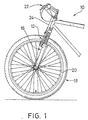
- a front portion of a bicycle 10 is illustrated having a bicycle braking device 12 with a pair of friction pads or brake shoes 14 according to the present invention.
- Bicycles and their various components are well-known in the prior art, and thus, bicycle 10 and its various components will not be discussed or illustrated in detail herein, except for the components of bicycle 10 which relate to the braking device 12 in accordance with the present invention. In other words, only bicycle braking device 12 will be discussed and illustrated in detail herein.
- the front braking device 12 is illustrated as being coupled to front fork 16 of bicycle 10 in a relatively conventional manner.
- another braking device 12 is preferably coupled to the rear fork of bicycle 10 in a conventional manner.
- the front braking device 12 is a "cantilever type" of braking device.
- other types of bicycle braking devices that can utilize the brake shoes 14 of the present invention, as needed and/or desired.
- braking device 12 is coupled to the front fork 16 of the bicycle 10 such that it can move between a release position and a brake position.
- the brake shoes 14 of the braking device 12 do not engage the rim 20 so that the wheel 18 is free to rotate.
- the brake shoes 14 of the braking device 12 are pivoted such that the bicycle brake shoes 14 grip the braking surfaces of the rim 20 to decelerate or stop rotation of the wheel 18.
- the rider will operate the brake operating device 22 which in turn will pull cable 24 to cause the brake shoes 14 of the braking device 12 to engage the braking surfaces of the rim 20 of the wheel 18.
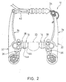
- each braking device 12 has a pair of brake mechanisms 32 that are pivotally coupled to front fork 16.
- Each of the braking mechanisms 32 have a brake arm 34, a four-bar link mechanism 36, and a pair of friction pad supports or brake shoe holders 38 to which the friction pads or brake shoes 14 are secured in a conventional manner.
- a link 42 and one end of cable 24 interconnect the upper ends of brake arms 34 such that the brake mechanisms 32 pivot together in a conventional manner.
- the brake shoe holders 38 are coupled to the brake arms 34 by a center post 44 and a nut 46 that is attached to the four-bar link mechanism 36.
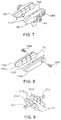
- each of the bicycle brake shoes 14 has an attachment portion 14a and a rim contacting portion 14b with a braking surface.
- the bicycle brake shoes 14 are formed from a non-sulfur cross-linked polymer such as butadiene rubber (BR) or acrylonitrile-butadiene rubber (NBR) being cross-linked with a metal, preferably zinc methacrylate and a binder such as peroxide.
- BR butadiene rubber
- NBR acrylonitrile-butadiene rubber
- the bicycle brake shoes 14 of the present invention is vulcanized by a peroxide such as Di-Cup 40C instead of by sulfur.
- the attachment portion 14a and the rim contacting portion 14b are integrally formed as a one-piece, unitary member.
- both the attachment portion 14a and the rim contacting portion 14b are form of butadiene rubber or acrylonitrile-butadiene rubber cross-linked with the zinc methacrylate in this embodiment.
- the attachment portion 14a and the rim contacting portion 14b can be formed of separate pieces that are integrally attached together by adhesive or the like.
- the brake shoe holders 38 can be eliminated in this embodiment by having one end of the center post 44 embedded within the attachment portion 14a.
- attachment portions 114a and the rim contacting portions 114b are formed of separate pieces that are integrally attached together by adhesive or the like.
- the rim contacting portion 14b is formed from butadiene rubber or acrylonitrile-butadiene rubber being cross-linked with zinc methacrylate and peroxide, while the attachment portions 114a can be constructed of any other suitable material.
- Each of the attachment portions 114a is fixedly attached to one of the rim contacting portions 114b by a suitable means such as adhesive or the like.
- the attachment portions 114a are received in recesses of the brake shoe holders 138. Threaded fasteners or screws 138a are utilized to fixedly secure the bicycle brake shoes 114 to the brake shoe holders 138 in a relatively conventional manner.
- bicycle brake shoes 214 are illustrated having attachment portions 214a and rim contacting portions 214b in accordance with yet another embodiment of the present invention.
- the brake holders have been eliminated by using center posts 244 that are embedded in the brake shoes 214.
- one end of each center post 244 is embedded within one of the attachment portions 214a during the molding process of the bicycle brake shoes 214.
- both the attachment portion 214a and the rim contacting portion 214b of each of the bicycle brake shoes 214 are integrally formed as a one-piece, unitary member.
- both the attachment portions 214a and the rim contacting portion 214b of each of the bicycle brake shoes 214 are formed of butadiene rubber or acrylonitrile-butadiene rubber cross-linked with the zinc methacrylate and the peroxide.
- the center posts 244 are embedded within the attachment portions 214a during the molding process of the bicycle brake shoes 214. More specifically, the end of the center posts 244 that are embedded within the attachment portions 214a have a flange member embedded within the attachment portions 214a.
- the attachment portions 214a can be constructed of a separate material from the rim contacting portions 214b, as needed and/or desired.
- numerous other manufacturing techniques may be utilized in constructing bicycle brake shoes in accordance with the present invention.
- the attachment portion 14a and the rim contacting portion 14b are further formed by cross-linking the butadiene rubber or acrylonitrile-butadiene rubber with zinc methacrylate and a binder such as peroxide.
- the brake shoes 14 are formed without utilizing conventional sulfur cross-linking.
- the attachment portion 14a and the rim contacting portion 14b can be formed with additional materials such as, but not limited to, one or more of the following materials alumina, talc, barium sulfate, zinc bloom, stearic acid, zinc stearate, calcium stearate, and paraffin wax. Examples of some possible blends for manufacturing the bicycle brake shoes 14 in accordance with the present invention are shown below in TABLE 1.
- the attachment portions 114a or 214a and the rim contacting portions 114b or 214b can also be manufactured with the materials listed in the blend examples of TABLE 1.
- the various materials for the blends of TABLE 1 are expressed in parts by weight.
- the various materials to be blended are first measured by weight to the appropriate weight percentage and then mixed together.
- the mixture is processed in a conventional manner to form an extruded sheet of rubber.
- the sheet of rubber is than cut into individual sheets that are used in a conventional molding process to form a plurality of bicycle brake shoes 14 with rim contacting portions 14b composed of the rubber compound, as mentioned above.
- the attachment portion 14a and the rim contacting portion 14b are preferably integrally formed as a one-piece, unitary member.
- the attachment portion 14a can be formed of separate piece that is integrally attached to the rim contacting portion 14b by adhesive or the like after molding the rim contacting portion 14b as mentioned above.
- one end of the center post 44 can be embedded within the attachment portion 14a and/or the rim contacting portion 14b during the molding process mentioned above.
- the bicycle brake shoes 14 of the present invention have been manufactured and compared to prior art bicycle brake shoes (sulfur cross-linking) as seen in the TABLE 2 below.
- a comparison of the wet braking distance (m) and the amount of rim wear is illustrated between test samples of the bicycle brake shoes 14 of the present invention and test samples of the prior art bicycle brake shoes in TABLE 2 below.
- Examples 1 and 2 of the present invention are composed of the materials listed in Blend Examples 6 and 7, respectively, of TABLE 1.
- the Test Examples 1-5 of the present invention are all composed of butadiene rubber being cross-linked with peroxide (PO) and zinc methacrylate.
- the Test Examples 1-3 of the prior art on the other hand; all utilize sulfur for cross-linking the rubber.
- the addition of alumina (refractory filler) substantially improves the wet braking distance but substantially increases the amount of rim wear.
- the prior art Test Example 3 illustrates a bicycle brake shoe in which no refractory filler is utilized.
- the braking distances for bicycle brake shoes 14 of Test Examples 1-5 of the present invention in wet conditions are substantially equal to the braking distances for the prior art bicycle brake shoes (Examples 1 and 2 of the prior art) that use alumina as a refractory filler and substantially better than the prior art bicycle brake shoes (Example 3 of the prior art) that do not use a refractory filler such as alumina.
- the amount of rim wear for bicycle brake shoes 14 of Test Examples 1-5 of the present invention is substantially reduced as compared to prior art bicycle brake shoes (Examples 1 and 2 of the prior art), where a substantial amount of alumina is used.
- the wet braking distance is very poor, while very little rim wear occurs.
Abstract
Description
| Blend Examples | |||||||||
| 1 | 2 | 3 | 4 | 5 | 6 | 7 | 8 | 9 | |
| Butadiene Rubber | 100 | 100 | 100 | 100 | 100 | 100 | 100 | 100 | 100 |
| Alumina | 7.5 | 7.5 | 7.5 | 7.5 | 7.5 | 0 | 0 | 0 | 7.5 |
| Zinc Methacrylate | 25 | 25 | 20 | 15 | 10 | 15 | 25 | 25 | 25 |
| Talc | 190 | 220 | 220 | 220 | 220 | 220 | 220 | 0 | 0 |
| Barium Sulfate | 0 | 0 | 0 | 0 | 0 | 0 | 0 | 440 | 440 |
| | 20 | 20 | 20 | 20 | 10 | 20 | 20 | 20 | 20 |
| Stearic Acid | 15 | 15 | 15 | 15 | 15 | 15 | 15 | 15 | 15 |
| Zinc Stearate | 15 | 15 | 15 | 15 | 15 | 15 | 15 | 15 | 15 |
| | 10 | 10 | 10 | 10 | 10 | 10 | 10 | 10 | 10 |
| | 10 | 10 | 10 | 10 | 10 | 10 | 10 | 10 | 10 |
| Di-Cup 40C | 1.5 | 1.5 | 1.5 | 1.5 | 1.5 | 1.5 | 1.5 | 1.5 | 1.5 |
| Total | 394.0 | 424.0 | 419.0 | 414.0 | 399.0 | 406.5 | 416.5 | 636.5 | 644 |
| Test Examples | ||||||||
| PRIOR ART | PRESENT INVENTION | |||||||
| Product | 1 | 2 | 3 | 1 | 2 | 3 | 4 | 5 |
| Cross-linking Configuration | Sulfur | Sulfur | Sulfur | PO | PO | PO | PO | PO |
| Polymer | BR | BR | NBR | BR | BR | BR | BR | BR |
| Amount of Alumina (Refractory Filler) | 30 | 80 | 0 | 0 | 0 | 10 | 10 | 10 |
| Carbon Black | yes | yes | yes | no | no | no | no | no |
| Amount of | 12 | 12 | 8 | 0 | 0 | 0 | 0 | 0 |
| Zinc Methacrylate | 0 | 0 | 0 | 15 | 25 | 25 | 20 | 15 |
| Di-Cup 40C (Peroxide) | 0 | 0 | 0 | 1.5 | 1.5 | 1.5 | 1.5 | 1.5 |
| Wet Braking Distance (m) | 5.0 | 4.3 | 8.4 | 5.0 | 4.9 | 5.1 | 4.4 | 4.6 |
| Rim Wear (Assessed on 5 Ranks) | 3 | 1 | 5 | 5 | 5 | 3 | 4 | 4 |
| Tensile Strength | 123 | no data | 75 | 103 | 139 | 136 | 119 | 109 |
Claims (21)
- A bicycle brake shoe (14, 114, 214) comprising:
a rim contacting portion (14b, 114b, 214b) with a braking surface formed from a polymer selected from the group consisting of butadiene rubber and acrylonitrile-butadiene rubber that is cross-linked with zinc methacrylate. - A bicycle brake shoe (14, 114, 214) according to claim 1, wherein
said rim contacting portion (14b, 114b, 214b) is further formed by cross-linking said polymer with peroxide. - A bicycle brake shoe (14, 114, 214) according to claim 1 or 2, wherein
said rim contacting portion (14b, 114b, 214b) is further formed with stearic acid. - A bicycle brake shoe (14, 114, 214) according to any of the preceding claims, wherein said rim contacting portion (14b, 114b, 214b) is further formed with zinc stearate.
- A bicycle brake shoe (14, 114, 214b) according to any of the preceding claims, wherein
said rim contacting portion (14b, 114b, 214b) is further formed with calcium stearate. - A bicycle brake shoe (14, 114, 214) according to any of the preceding claims, wherein said rim contacting portion (14b, 114b, 214b) is further formed with alumina.
- A bicycle brake shoe (14, 114, 214) according to any of the preceding claims, wherein said rim contacting portion (14b, 114b, 214b) is further formed of paraffin wax.
- A bicycle brake shoe (14, 114, 214) according to any of the preceding claims, wherein said rim contacting portion (14b, 114b, 214b) is further formed with barium sulfate.
- A bicycle brake shoe (14, 114, 214) according to any of the preceding claims, further comprising
an attachment portion (14a, 114a, 214a) fixedly coupled to said rim contacting portion (14b, 114b, 214b). - A bicycle brake shoe (14, 114, 214) according to claim 9, wherein
said attachment portion (14a, 114a, 214a) and said rim contacting portion (14b, 114b, 214b) are integrally formed as a one-piece, unitary member from said polymer cross-linked with said zinc methacrylate. - A bicycle brake shoe (14, 114, 214) according to claim 9 or 10, wherein
said attachment portion (14a, 114a, 214a) has a fastening member with one end of said fastening member being embedded within said attachment portion (14a, 114a, 214a). - A bicycle brake shoe (14, 114, 214) according to claim 9, wherein
said attachment portion (14a, 114a, 214a) and said rim contacting portion (14b, 114b, 214b) are separate pieces that are integrally attached together. - A bicycle brake shoe (14, 114, 214) according to claims 9 to 12, further comprising
a shoe holder (38, 138) removably coupled thereto said attachment portion (14a, 114a, 214a). - A bicycle brake shoe (14, 114, 214) comprising:
a rim contacting portion (14b, 114b, 214b) with a braking surface formed from a polymer selected from the group consisting of butadiene rubber and acrylonitrile-butadiene rubber that is cross-linked with peroxide and a metal ion cross-linking. - A bicycle brake shoe (14, 114, 214) according to claim 14, further comprising
an attachment portion (14a, 114a, 214a) fixedly coupled to said rim contacting portion (14b, 114b, 214b). - A bicycle brake shoe (14, 114, 214) according to claim 14 or 15, wherein
said attachment portion (14a, 114a, 214a) and said rim contacting portion (14b, 114b, 214b) are integrally formed as a one-piece, unitary member from said polymer. - A bicycle brake shoe (14, 114, 214) according to claims 14 to 16, wherein
said attachment portion (14a, 114a, 214a) has a fastening member with one end of said fastening member being embedded within said attachment portion (14a, 114a, 214a). - A bicycle brake shoe (14, 114, 214) according to claim 14 or 15, wherein
said attachment portion (14a, 114a, 214a) and said rim contacting portion (14b, 114b, 214b) are separate pieces that are integrally attached together. - A bicycle brake shoe (14, 114, 214) comprising:
a rim contacting portion (14b, 114b, 214b) with a braking surface formed from a non-sulfur cross-linked polymer that is cross-linked with zinc methacrylate. - A bicycle brake shoe (14, 114, 214) according to claim 19, wherein
said rim contacting portion (14b, 114b, 214b) is further formed by cross-linking said polymer with peroxide. - A bicycle brake shoe (14, 114, 214) according to claim 19 or 20, wherein
said polymer is selected from the group consisting of butadiene rubber and acrylonitrile-butadiene rubber.
Applications Claiming Priority (2)
| Application Number | Priority Date | Filing Date | Title |
|---|---|---|---|
| US593680 | 2000-06-14 | ||
| US09/593,680 US6386329B1 (en) | 2000-06-14 | 2000-06-14 | Bicycle brake shoe |
Publications (3)
| Publication Number | Publication Date |
|---|---|
| EP1164076A2 true EP1164076A2 (en) | 2001-12-19 |
| EP1164076A3 EP1164076A3 (en) | 2003-02-12 |
| EP1164076B1 EP1164076B1 (en) | 2008-08-27 |
Family
ID=24375696
Family Applications (1)
| Application Number | Title | Priority Date | Filing Date |
|---|---|---|---|
| EP01111550A Expired - Lifetime EP1164076B1 (en) | 2000-06-14 | 2001-05-11 | Bicycle brake shoe |
Country Status (6)
| Country | Link |
|---|---|
| US (1) | US6386329B1 (en) |
| EP (1) | EP1164076B1 (en) |
| JP (1) | JP2002081477A (en) |
| CN (1) | CN1213896C (en) |
| DE (1) | DE60135520D1 (en) |
| TW (1) | TW593052B (en) |
Families Citing this family (5)
| Publication number | Priority date | Publication date | Assignee | Title |
|---|---|---|---|---|
| US20060144654A1 (en) * | 2005-01-06 | 2006-07-06 | Lin A P | Bicycle brake shoe |
| US20060144656A1 (en) * | 2005-01-06 | 2006-07-06 | Lin A P | Bicycle brake shoe |
| EP2520478B1 (en) * | 2011-05-02 | 2014-01-22 | CAMPAGNOLO S.r.l. | Brake pad for a bicycle |
| CN102401052B (en) * | 2011-11-11 | 2015-09-02 | 中国铁道科学研究院金属及化学研究所 | For the high friction composite brake shoe and its preparation method and application of high-power XHN5 locomotive |
| JPWO2021117333A1 (en) | 2019-12-09 | 2021-06-17 |
Family Cites Families (15)
| Publication number | Priority date | Publication date | Assignee | Title |
|---|---|---|---|---|
| JPS53131636A (en) * | 1977-04-18 | 1978-11-16 | Shimano Industrial Co | Friction material for brake of bicycle |
| SU1445160A1 (en) | 1985-12-09 | 1992-09-23 | Предприятие П/Я В-8570 | Polymer composition of friction purposes |
| JPS63130642A (en) * | 1986-11-20 | 1988-06-02 | Daikin R M Kk | Wet friction material composition |
| JPH0676500B2 (en) * | 1990-01-05 | 1994-09-28 | 住友ゴム工業株式会社 | Rubber member for separation pad |
| JPH055092A (en) | 1991-02-14 | 1993-01-14 | Akebono Brake Ind Co Ltd | Frictional material used in oil |
| JP2599056B2 (en) * | 1991-10-04 | 1997-04-09 | 東海ゴム工業株式会社 | Rubber composition |
| JP3421360B2 (en) | 1992-02-14 | 2003-06-30 | 株式会社シマノ | Exterior braking system |
| WO1993022377A1 (en) * | 1992-04-29 | 1993-11-11 | Akzo Nobel N.V. | Anti-fatique coagents for rubber vulcanization |
| JP3451129B2 (en) * | 1994-05-25 | 2003-09-29 | 株式会社シマノ | Bicycle brake shoes |
| US5636716A (en) | 1995-03-07 | 1997-06-10 | Shimano, Inc. | Bicycle brake device |
| JPH09290467A (en) | 1996-04-24 | 1997-11-11 | Mitsuboshi Belting Ltd | Toothed belt |
| CA2203617C (en) * | 1996-04-26 | 2000-08-08 | Hiroshi Jonen | Power transmission belt |
| JP3323398B2 (en) * | 1996-06-11 | 2002-09-09 | 株式会社シマノ | Bicycle braking device |
| JP3770285B2 (en) * | 1996-09-27 | 2006-04-26 | 日本ゼオン株式会社 | Highly saturated copolymer rubber containing carboxylated nitrile groups |
| WO2000004098A1 (en) * | 1998-07-16 | 2000-01-27 | Aktieselskabet Roulunds Fabriker | Elastomeric composition and the use thereof in an article subject to dynamic loading |
-
2000
- 2000-06-14 US US09/593,680 patent/US6386329B1/en not_active Expired - Fee Related
-
2001
- 2001-03-23 TW TW090106996A patent/TW593052B/en active
- 2001-05-11 EP EP01111550A patent/EP1164076B1/en not_active Expired - Lifetime
- 2001-05-11 DE DE60135520T patent/DE60135520D1/en not_active Expired - Lifetime
- 2001-05-17 CN CN01117778.0A patent/CN1213896C/en not_active Expired - Fee Related
- 2001-06-13 JP JP2001178877A patent/JP2002081477A/en active Pending
Non-Patent Citations (1)
| Title |
|---|
| None |
Also Published As
| Publication number | Publication date |
|---|---|
| TW593052B (en) | 2004-06-21 |
| US6386329B1 (en) | 2002-05-14 |
| EP1164076B1 (en) | 2008-08-27 |
| CN1213896C (en) | 2005-08-10 |
| JP2002081477A (en) | 2002-03-22 |
| CN1328944A (en) | 2002-01-02 |
| DE60135520D1 (en) | 2008-10-09 |
| EP1164076A3 (en) | 2003-02-12 |
Similar Documents
| Publication | Publication Date | Title |
|---|---|---|
| US9795184B2 (en) | Shoe positioning plate for bicycle shoes | |
| EP0826588B1 (en) | Bicycle pedal assembly and shoe cleat | |
| US6490948B2 (en) | Bicycle pedal | |
| FI82005C (en) | BROMSSYSTEM FOER CYKLAR. | |
| US20030051575A1 (en) | Bicycle pedal assembly | |
| EP0826587B1 (en) | Bicycle pedal with gap adjusting mechanism | |
| EP0826586B1 (en) | Low profile bicycle pedal with top and bottom side clamping arrangements | |
| USRE38975E1 (en) | Bicycle disc brake | |
| US9656720B2 (en) | Bicycle pedal | |
| TWM248727U (en) | Bicycle pedal | |
| US6386329B1 (en) | Bicycle brake shoe | |
| EP0799762B1 (en) | Bicycle brake shoe holder | |
| JP2000142537A (en) | Bicycle pedal | |
| US6196084B1 (en) | Bicycle cleat | |
| US20060144650A1 (en) | Bicycle brake shoe | |
| EP0710602B1 (en) | Brake shoe for bicycle | |
| US20060144656A1 (en) | Bicycle brake shoe | |
| EP0879756A2 (en) | Brake lever having a rapid brake shoe clearance adjusting mechanism | |
| US6105462A (en) | Bicycle pedal | |
| EP0891921A2 (en) | Bicycle brake assembly | |
| CN211231361U (en) | Brake caliper and brake caliper lever assembly | |
| JPH0322355B2 (en) | ||
| WO1998010979A1 (en) | Aerodynamic bicycle brake lever | |
| JPH0630642B2 (en) | Ski shoe heel fastener with a built-in ski break | |
| CN116788416A (en) | Pedal of bicycle |
Legal Events
| Date | Code | Title | Description |
|---|---|---|---|
| PUAI | Public reference made under article 153(3) epc to a published international application that has entered the european phase |
Free format text: ORIGINAL CODE: 0009012 |
|
| AK | Designated contracting states |
Kind code of ref document: A2 Designated state(s): AT BE CH CY DE DK ES FI FR GB GR IE IT LI LU MC NL PT SE TR |
|
| AX | Request for extension of the european patent |
Free format text: AL;LT;LV;MK;RO;SI |
|
| PUAL | Search report despatched |
Free format text: ORIGINAL CODE: 0009013 |
|
| RIC1 | Information provided on ipc code assigned before grant |
Ipc: 7C 08L 9/02 B Ipc: 7B 62L 1/00 A Ipc: 7F 16D 69/02 B Ipc: 7B 62L 1/14 B |
|
| AK | Designated contracting states |
Designated state(s): AT BE CH CY DE DK ES FI FR GB GR IE IT LI LU MC NL PT SE TR |
|
| AX | Request for extension of the european patent |
Extension state: AL LT LV MK RO SI |
|
| 17P | Request for examination filed |
Effective date: 20030206 |
|
| AKX | Designation fees paid |
Designated state(s): DE FR GB IE IT NL |
|
| RAP1 | Party data changed (applicant data changed or rights of an application transferred) |
Owner name: SHIMANO INC. |
|
| 17Q | First examination report despatched |
Effective date: 20061206 |
|
| 17Q | First examination report despatched |
Effective date: 20061206 |
|
| GRAP | Despatch of communication of intention to grant a patent |
Free format text: ORIGINAL CODE: EPIDOSNIGR1 |
|
| GRAS | Grant fee paid |
Free format text: ORIGINAL CODE: EPIDOSNIGR3 |
|
| GRAA | (expected) grant |
Free format text: ORIGINAL CODE: 0009210 |
|
| AK | Designated contracting states |
Kind code of ref document: B1 Designated state(s): DE FR GB IE IT NL |
|
| REG | Reference to a national code |
Ref country code: GB Ref legal event code: FG4D |
|
| REG | Reference to a national code |
Ref country code: IE Ref legal event code: FG4D |
|
| REF | Corresponds to: |
Ref document number: 60135520 Country of ref document: DE Date of ref document: 20081009 Kind code of ref document: P |
|
| PG25 | Lapsed in a contracting state [announced via postgrant information from national office to epo] |
Ref country code: NL Free format text: LAPSE BECAUSE OF FAILURE TO SUBMIT A TRANSLATION OF THE DESCRIPTION OR TO PAY THE FEE WITHIN THE PRESCRIBED TIME-LIMIT Effective date: 20080827 |
|
| PLBE | No opposition filed within time limit |
Free format text: ORIGINAL CODE: 0009261 |
|
| STAA | Information on the status of an ep patent application or granted ep patent |
Free format text: STATUS: NO OPPOSITION FILED WITHIN TIME LIMIT |
|
| 26N | No opposition filed |
Effective date: 20090528 |
|
| PG25 | Lapsed in a contracting state [announced via postgrant information from national office to epo] |
Ref country code: IT Free format text: LAPSE BECAUSE OF FAILURE TO SUBMIT A TRANSLATION OF THE DESCRIPTION OR TO PAY THE FEE WITHIN THE PRESCRIBED TIME-LIMIT Effective date: 20080827 |
|
| GBPC | Gb: european patent ceased through non-payment of renewal fee |
Effective date: 20090511 |
|
| REG | Reference to a national code |
Ref country code: FR Ref legal event code: ST Effective date: 20100129 |
|
| REG | Reference to a national code |
Ref country code: IE Ref legal event code: MM4A |
|
| PG25 | Lapsed in a contracting state [announced via postgrant information from national office to epo] |
Ref country code: IE Free format text: LAPSE BECAUSE OF NON-PAYMENT OF DUE FEES Effective date: 20090511 Ref country code: FR Free format text: LAPSE BECAUSE OF NON-PAYMENT OF DUE FEES Effective date: 20090602 |
|
| PG25 | Lapsed in a contracting state [announced via postgrant information from national office to epo] |
Ref country code: GB Free format text: LAPSE BECAUSE OF NON-PAYMENT OF DUE FEES Effective date: 20090511 |
|
| PGFP | Annual fee paid to national office [announced via postgrant information from national office to epo] |
Ref country code: DE Payment date: 20170502 Year of fee payment: 17 |
|
| REG | Reference to a national code |
Ref country code: DE Ref legal event code: R119 Ref document number: 60135520 Country of ref document: DE |
|
| PG25 | Lapsed in a contracting state [announced via postgrant information from national office to epo] |
Ref country code: DE Free format text: LAPSE BECAUSE OF NON-PAYMENT OF DUE FEES Effective date: 20181201 |