EP1163884A1 - Intracorporeal lithotripter for removing calculi - Google Patents
Intracorporeal lithotripter for removing calculi Download PDFInfo
- Publication number
- EP1163884A1 EP1163884A1 EP01113411A EP01113411A EP1163884A1 EP 1163884 A1 EP1163884 A1 EP 1163884A1 EP 01113411 A EP01113411 A EP 01113411A EP 01113411 A EP01113411 A EP 01113411A EP 1163884 A1 EP1163884 A1 EP 1163884A1
- Authority
- EP
- European Patent Office
- Prior art keywords
- sonotrode
- metal probe
- ultrasonic transducer
- vibration excitation
- horn
- Prior art date
- Legal status (The legal status is an assumption and is not a legal conclusion. Google has not performed a legal analysis and makes no representation as to the accuracy of the status listed.)
- Granted
Links
Images
Classifications
-
- A—HUMAN NECESSITIES
- A61—MEDICAL OR VETERINARY SCIENCE; HYGIENE
- A61B—DIAGNOSIS; SURGERY; IDENTIFICATION
- A61B17/00—Surgical instruments, devices or methods, e.g. tourniquets
- A61B17/22—Implements for squeezing-off ulcers or the like on the inside of inner organs of the body; Implements for scraping-out cavities of body organs, e.g. bones; Calculus removers; Calculus smashing apparatus; Apparatus for removing obstructions in blood vessels, not otherwise provided for
- A61B17/22004—Implements for squeezing-off ulcers or the like on the inside of inner organs of the body; Implements for scraping-out cavities of body organs, e.g. bones; Calculus removers; Calculus smashing apparatus; Apparatus for removing obstructions in blood vessels, not otherwise provided for using mechanical vibrations, e.g. ultrasonic shock waves
- A61B17/22012—Implements for squeezing-off ulcers or the like on the inside of inner organs of the body; Implements for scraping-out cavities of body organs, e.g. bones; Calculus removers; Calculus smashing apparatus; Apparatus for removing obstructions in blood vessels, not otherwise provided for using mechanical vibrations, e.g. ultrasonic shock waves in direct contact with, or very close to, the obstruction or concrement
Definitions
- the invention relates to a device for removing body stones with an intracorporeal lithotripter according to the preamble of claim 1.
- EP 0 421 285 B1 describes an intracorporeal lithotripsy a device is known in which a metal probe or sonotrode by a electrically controlled ultrasonic transducers for longitudinal vibrations is excited. With the distal end in the working channel of an endoscope used probe can therefore cause the destruction of a body stone become.
- the ultrasonic transducer has two piezoceramic disks trained, which are clamped between a reflector and a horn. The Both discs are used for periodic vibration excitation of the sonotrode controlled by a circuit arrangement that consists of a voltage controlled Oscillator exists, whose output signal via an output amplifier and delivered an output transformer to the two piezoceramic disks becomes.
- the circuit arrangement also includes a phase comparator, which the phases of the output voltage and the output current of the Output transformer compares and a control voltage to control the Oscillator generated.
- a lithotripter is known in which the proximal Pneumatically driven impact part is applied to the end of a metal probe becomes a metal probe with an impact energy obtained thereby to generate continuous shock or pressure wave up to its distal end.
- This shock wave or pressure wave acts on a body stone, with the tip of the probe is kept in contact with the stones.
- shock wave lithotripters the other versions also have an electric drive of the striking part generally result in a relatively simple construction of the device with very good fragmentation performance also on harder ones Body stones. With these lithotripters, however, the stone crushing has to towards an absorbable particle size is still relatively time-consuming become.
- the invention has for its object a device of the aforementioned Form in such a way that taking into account the preliminary and Disadvantages of these known methods a more flexible stone destruction can be carried out is.
- the device according to the invention thus has a first application mode, in which a periodic oscillation of the metal probe or sonotrode essentially as in the previously known ultrasonic lithotripters the connected circuit arrangement to form a standing wave is caused a sinusoidal movement of the probe tip in axial Direction.
- a periodic oscillation of the metal probe or sonotrode essentially as in the previously known ultrasonic lithotripters the connected circuit arrangement to form a standing wave is caused a sinusoidal movement of the probe tip in axial Direction.
- the ultrasonic transducer With an impulsive Vibration excitation of the metal probe or sonotrode according to a second Application mode of the device, on which with a simple switch can be switched, however, the ultrasonic transducer with a single Voltage pulse driven to provide an output power, which suddenly causes the at least one piezoceramic disk to expand, so that in the metal probe or sonotrode connected to the horn Pressure wave is generated, which is introduced into the body stone at the tip of the probe Pressure pulse generated.
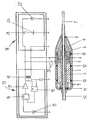
- the device according to the invention consists of an ultrasonic transducer, which as a piezoelectric transducer with two piezoceramic disks 1 and 2 with an arrangement between a reflector 3 and a horn 4 is formed.
- the arrangement of the ultrasonic transducer consisting of these components is held together by a hollow clamping screw 5, which the two ceramic Discs 1, 2 and the reflector 3 axially penetrated and with the horn 4th is screwed via a screw thread 6.
- a hollow clamping screw 5 which the two ceramic Discs 1, 2 and the reflector 3 axially penetrated and with the horn 4th is screwed via a screw thread 6.
- the horn 4 tubular metal probe or sonotrode 7 screwed to a screw attachment 8, so that the cavity of the clamping screw 5 in the cavity of the Metal probe or sonotrode 7 continues axially.
- the two piezoceramic disks 1, 2 are for one on the metal probe 7 forwarded vibration generation connected to an electrical control, those with a first circuit arrangement 13 and a separate one second circuit arrangement 14 is formed.
- the circuit arrangement 13 is for and periodic vibration excitation of the metal probe designed essentially with a voltage-controlled oscillator 15, the via a U / F converter 16 and a downstream amplifier 17 with a Impedance transformer 18 is connected.
- the impedance transformer 18 is fed back to the U / F converter 16 via a phase comparator 19, which the phases of the output voltage and the output current of the impedance transformer 18 compares and a control voltage for controlling the oscillator 15 generated. Therefore, one for the periodic vibration excitation of the Metal probe 7 via the connection 20 to a suitable output signal the two piezoceramic disks 1, 2 delivered.
- the piezoceramic disks 1, 2 are next to it with the second circuit arrangement 14 connected by which a pulsed vibration excitation the metal probe 7 is obtained.
- the circuit arrangement 14 consists of a Voltage source 22 and a capacitor 23 in a first switching position a switch 21 is charged by the voltage source 22.
- the condenser 23 is discharged in a second switch position of the changeover switch 21, so that a pulsed vibration excitation of the metal probe is obtained.
- the capacitor charge is applied once via the connection 20 the two piezoceramic disks 1, 2 forwarded, with the output signal the circuit arrangement 14 a much higher performance at the piezoelectric transducers can be delivered as with the output signal the circuit arrangement relevant for the periodic vibration excitation 13.
- Metal probe 7 expediently made of a material with a same acoustic impedance. Coming as preferred materials Stainless steel and titanium are considered. Furthermore, the horn 4 should be in one axial direction approximately on the cross section of the screw neck 8 of the metal probe 7 tapered envelope surface in the formation of an exponential curve be, whereby other geometries can also be taken into account for the envelope surface.
- the support of the ultrasound transducer effected with the elastic means 10, 11 on the surrounding housing should be designed such that both for the periodic as well as for the pulsed vibration excitation of the Metal probe each optimal work results can be obtained.
- the metal probe can also be a switch device additional to the changeover switch 21 be provided between separate connection connections the ultrasonic transducer is switchable.
Abstract
Description
Die Erfindung bezieht sich auf eine Vorrichtung zum Entfernen von Körpersteinen
mit einem intrakorporalen Lithotripter gemäß dem Oberbegriff des Anspruches 1.The invention relates to a device for removing body stones
with an intracorporeal lithotripter according to the preamble of
Für die Entfernung von Körpersteinen aus Körperhöhlen ist es bei Überschreitung einer für einen natürlichen Abgang noch ausreichenden Steingröße regelmäßig erforderlich, die Körpersteine zunächst zu zerkleinern, wobei die Zerkleinerung in kleine, spontan abgangsfähige oder direkt aus dem Körper ausspülbare Partikel vorgenommen wird. Die Zerkleinerung der Körpersteine wird dabei durch mechanische Druck- und Zugspannungen vorgenommen, die bei der intrakorporalen Lithotripsie mit dem distalen Ende einer als Wellenleiter dienenden Metallsonde auf die Körpersteine ausgeübt werden. Solche Spannungen führen zu einem Absprengen von Fragmenten aus der Oberfläche eines Steines und bewirken schließlich dessen Zertrümmerung. Für diese Steinzertrümmerung existiert allgemein das Problem einer geeigneten Energieübertragung mit besonderer Beachtung einer Vermeidung von Nebeneffekten auf das biologische Gewebe, das für die Steinzertrümmerung daher nicht als ein Widerlager dienen sollte.For the removal of body stones from body cavities, it is exceeded a stone size that is still sufficient for a natural finish necessary to first crush the body stones, the crushing in small, spontaneously removable particles that can be flushed out of the body is made. The crushing of the body stones is done by mechanical Compressive and tensile stresses made in intracorporeal lithotripsy with the distal end of a metal probe serving as a waveguide the body stones are exercised. Such tensions lead to blasting of fragments from the surface of a stone and cause finally its smashing. For this stone crushing generally exists the problem of suitable energy transmission with special attention avoiding side effects on the biological tissue that is responsible for the stone crushing should therefore not serve as an abutment.
Zur Durchführung einer intrakorporalen Lithotripsie ist aus der EP 0 421 285 B1 eine Vorrichtung bekannt, bei welcher eine Metallsonde oder Sonotrode durch einen elektrisch angesteuerten Ultraschallwandler zu longitudinalen Schwingungen angeregt wird. Mit dem distalen Ende der in den Arbeitskanal eines Endoskops eingesetzten Sonde kann daher die Zertrümmerung eines Körpersteins veranlaßt werden. Der Ultraschallwandler ist dabei mit zwei piezokeramischen Scheiben ausgebildet, die zwischen einem Reflektor und einem Horn verspannt sind. Die beiden Scheiben werden für eine periodische Schwingungsanregung der Sonotrode durch eine Schaltungsanordnung angesteuert, die aus einem spannungsgesteuerten Oszillator besteht, dessen Ausgangssignal über einen Ausgangsverstärker und einen Ausgangsübertrager an die beiden piezokeramischen Scheiben angeliefert wird. Die Schaltungsanordnung umfaßt daneben noch einen Phasenkomparator, der die Phasen der Ausgangsspannung und des Ausgangsstroms des Ausgangsübertragers vergleicht sowie eine Regelspannung zur Steuerung des Oszillators erzeugt. Mit einer Vorrichtung dieser Ausbildung lassen sich die Körpersteine in aller Regel zu sehr feinen Fragmenten zertrümmern. Für die Feinfragmente wird dabei eine Partikelgröße erhalten, die ein meistens problemloses Absaugen durch einen axialen Hohlraum der Sonde hindurch bis hin zu ihrem proximalen Ende erlaubt, an welchem ein durch den Ultraschallwandler hindurchgeführter Sauganschluß zur Wirkung gebracht ist. Die Steinzertrümmerung mittels solcher Ultraschall-Lithotripter ist jedoch relativ zeitaufwändig, da sich mit dem distalen Ende der hohlen Sonotrode bei den für eine gewebeschonende Steinbearbeitung üblichen Ultraschallfrequenzen von etwa 20 bis 25 kHz und Amplituden der Sondenspitze bis etwa 50 µm die Steinzertrümmerung nur reichlich langsam fortführen läßt. Erschwerungen ergeben sich dabei auch bei den härteren Körpersteinen, die sich bei den Ultraschallfrequenzen und Amplituden dieser Größenordnung nicht spontan abschaben lassen, sodaß ihre Bearbeitung entweder sehr lange dauert oder überhaupt nicht möglich ist.EP 0 421 285 B1 describes an intracorporeal lithotripsy a device is known in which a metal probe or sonotrode by a electrically controlled ultrasonic transducers for longitudinal vibrations is excited. With the distal end in the working channel of an endoscope used probe can therefore cause the destruction of a body stone become. The ultrasonic transducer has two piezoceramic disks trained, which are clamped between a reflector and a horn. The Both discs are used for periodic vibration excitation of the sonotrode controlled by a circuit arrangement that consists of a voltage controlled Oscillator exists, whose output signal via an output amplifier and delivered an output transformer to the two piezoceramic disks becomes. The circuit arrangement also includes a phase comparator, which the phases of the output voltage and the output current of the Output transformer compares and a control voltage to control the Oscillator generated. With a device of this training, the body stones usually smash into very fine fragments. For the fine fragments a particle size is obtained which is mostly problem-free Aspirate through an axial cavity of the probe up to its proximal End allowed at which one passed through the ultrasonic transducer Suction port is brought into effect. The stone destruction by means of such an ultrasound lithotripter is relatively time-consuming, however, since the distal end of the hollow sonotrode for a stone treatment that is gentle on the tissue usual ultrasonic frequencies of about 20 to 25 kHz and amplitudes the tip of the probe down to about 50 µm the stone fragmentation is only very slow lets continue. Difficulties also arise with the harder stones, which are at the ultrasonic frequencies and amplitudes of this magnitude do not let it scrape off spontaneously, so that it will take a long time to process lasts or is not possible at all.
Aus der EP 0 317 507 B1 ist ein Lithotripter bekannt, bei welchem das proximale Ende einer Metallsonde mit einem pneumatisch angetriebenen Schlagteil beaufschlagt wird, um mit einer dadurch erhaltenen Stoßenergie eine die Metallsonde bis hin zu ihrem distalen Ende durchlaufende Stoß- bzw. Druckwelle zu erzeugen. Mit dieser Stoß- bzw. Druckwelle wird auf einen Körperstein eingewirkt, wobei mit der Sondenspitze eine Berührung mit den Steinen eingehalten wird. Solche Stoßwellen-Lithotripter, die bei anderen Ausführungen auch einen elektrischen Antrieb des Schlagteils aufweisen können, ergeben allgemein einen relativ einfachen Geräteaufbau bei ebenfalls sehr guten Fragmentierungsleistungen auch an härteren Körpersteinen. Bei diesen Lithotriptern muß jedoch die Steinzertrümmerung bis hin zu einer absaugfähigen Partikelgröße immer noch relativ zeitaufwändig fortgeführt werden.From EP 0 317 507 B1 a lithotripter is known in which the proximal Pneumatically driven impact part is applied to the end of a metal probe becomes a metal probe with an impact energy obtained thereby to generate continuous shock or pressure wave up to its distal end. This shock wave or pressure wave acts on a body stone, with the tip of the probe is kept in contact with the stones. Such shock wave lithotripters, the other versions also have an electric drive of the striking part generally result in a relatively simple construction of the device with very good fragmentation performance also on harder ones Body stones. With these lithotripters, however, the stone crushing has to towards an absorbable particle size is still relatively time-consuming become.
Der Erfindung liegt die Aufgabe zugrunde, eine Vorrichtung der eingangs genannten Art derart auszubilden, daß damit unter Berücksichtigung der Vor- und Nachteile dieser bekannten Verfahren eine flexiblere Steinzertrümmerung durchführbar ist.The invention has for its object a device of the aforementioned Form in such a way that taking into account the preliminary and Disadvantages of these known methods a more flexible stone destruction can be carried out is.
Diese Aufgabe wird erfindungsgemäß gelöst mit einer Vorrichtung der durch den
Anspruch 1 angegebenen Ausbildung, die mit den Merkmalen der weiteren Ansprüche
eine vorteilhafte Gestaltungsmöglichkeit erfährt.This object is achieved with a device by the
Die erfindungsgemäße Vorrichtung verfügt somit über einen ersten Anwendungsmodus, bei welchem eine periodische Schwingung der Metallsonde bzw. Sonotrode im wesentlichen wie bei den bisher bekannten Ultraschall-Lithotriptern durch die angeschlossene Schaltungsanordnung zur Ausbildung einer stehenden Welle veranlaßt wird, die eine sinusförmige Bewegung der Sondenspitze in axialer Richtung ergibt. Für eine Steinzertrümmerung kann dabei mit der Sondenspitze auf die Steinoberfläche mechanisch eingewirkt werden. Bei einer impulsförmigen Schwingungsanregung der Metallsonde bzw. Sonotrode gemäß einem zweiten Anwendungsmodus der Vorrichtung, auf welchen mit einem einfachen Umschalter umgeschaltet werden kann, wird dagegen der Ultraschallwandler mit einem einzigen Spannungsimpuls für die Bereitstellung einer Ausgangsleistung angesteuert, welche die wenigstens eine piezokeramische Scheibe plötzlich ausdehnen läßt, sodaß in der mit dem Horn verbundenen Metallsonde bzw. Sonotrode eine Druckwelle erzeugt wird, die an der Sondenspitze einen in den Körperstein eingeleiteten Druckimpuls erzeugt. Da ein solcher Druckimpuls eine einmalige Belastung der Sonotrode in einem relativ kleinen Zeitfenster ergibt, kann bei dieser impulsförmigen Schwingungsanregung über die Anschlußverbindung an den piezoelektrischen Wandler eine wesentlich höhere Leistung angeliefert werden als bei der periodischen Schwingungsanregung, sodaß bei diesem zweiten Anwendungsmodus Ergebnisse für die Steinzertrümmerung erzielbar sind, die vergleichbar mit denjenigen bei den bekannten Stoßwellen-Lithotriptern sind.The device according to the invention thus has a first application mode, in which a periodic oscillation of the metal probe or sonotrode essentially as in the previously known ultrasonic lithotripters the connected circuit arrangement to form a standing wave is caused a sinusoidal movement of the probe tip in axial Direction. For a stone fragmentation you can use the probe tip be mechanically acted on the stone surface. With an impulsive Vibration excitation of the metal probe or sonotrode according to a second Application mode of the device, on which with a simple switch can be switched, however, the ultrasonic transducer with a single Voltage pulse driven to provide an output power, which suddenly causes the at least one piezoceramic disk to expand, so that in the metal probe or sonotrode connected to the horn Pressure wave is generated, which is introduced into the body stone at the tip of the probe Pressure pulse generated. Because such a pressure pulse is a one-time load the sonotrode results in a relatively small time window pulse-shaped vibration excitation via the connection to the piezoelectric Converters can be delivered a much higher output than with periodic vibration excitation, so with this second mode of application Results for stone crushing are achievable which are comparable with those in the known shock wave lithotripters.
Ein Ausführungsbeispiel der erfindungsgemäßen Vorrichtung ist in der Zeichnung schematisch dargestellt und wird nachfolgend näher beschrieben.An embodiment of the device according to the invention is in the drawing is shown schematically and is described in more detail below.
Die erfindungsgemäße Vorrichtung besteht aus einem Ultraschallwandler, der als
ein piezoelektrischer Wandler mit zwei piezokeramischen Scheiben 1 und 2 mit
einer Anordnung zwischen einem Reflektor 3 und einem Horn 4 ausgebildet ist.
Die aus diesen Bauteilen bestehende Anordnung des Ultraschallwandlers wird
durch eine hohle Spannschraube 5 zusammengehalten, welche die beiden keramischen
Scheiben 1, 2 und den Reflektor 3 axial durchsetzt und mit dem Horn 4
über ein Schraubgewinde 6 verschraubt ist. Mit dem Horn 4 ist andererseits eine
rohrförmige Metallsonde bzw. Sonotrode 7 an einem Schraubansatz 8 verschraubt,
sodaß sich der Hohlraum der Spannschraube 5 in dem Hohlraum der
Metallsonde bzw. Sonotrode 7 axial fortsetzt.The device according to the invention consists of an ultrasonic transducer, which as
a piezoelectric transducer with two
Die mit der Spannschraube 5 zusammengehaltene und gegeneinander verspannte
Anordnung der einzelnen Bauteile des Ultraschallwandlers ist innerhalb
eines Gehäuses 9 untergebracht. Durch eine zweiteilige Ausbildung dieses Gehäuses
mit einer Teilungsebene im Bereich des Horns 4 ist dabei mit der Spannschraube
5 auch eine elastische Verspannung gegen das Gehäuse 9 erreicht, die
durch elastische Stützmittel in der Ausbildung von O-Ringen 10 und einer Dichtmanschette
11 eine Abstützung erfährt. Mit der hohlen Spannschraube 5 ist ein
äußerer Sauganschluß 12 verbunden, sodaß die Steinfragmente, die bei einer
Steinzertrümmerung am distalen Ende der Metallsonde 7 anfallen, über den Hohlraum
der Metallsonde 7 und den damit axial fluchtenden Hohlraum der Spannschraube
5 spontan abgesaugt werden können.The held together with the
Die beiden piezokeramischen Scheiben 1, 2 sind für eine an die Metallsonde 7
weitergeleitete Schwingungserzeugung mit einer elektrischen Ansteuerung verbunden,
die mit einer ersten Schaltungsanordnung 13 und einer davon getrennten
zweiten Schaltungsanordnung 14 ausgebildet ist. Die Schaltungsanordnung 13 ist
für eine periodische Schwingungsanregung der Metallsonde vorgesehen und ist
dafür im wesentlichen mit einem spannungsgesteuerten Oszillator 15 ausgebildet,
der über einen U/F-Wandler 16 und einen nachgeschalteten Verstärker 17 mit einem
Impedanz-Transformator 18 verbunden ist. Der Impedanz-Transformator 18
ist mit dem U/F-Wandler 16 über einen Phasenkomparator 19 rückgekoppelt, welcher
die Phasen der Ausgangsspannung und des Ausgangsstroms des Impedanz-Transformators
18 vergleicht und eine Regelspannung zur Steuerung des Oszillators
15 erzeugt. Daher wird ein für die periodische Schwingunsanregung der
Metallsonde 7 über die Anschlußverbindung 20 ein passendes Ausgangssignal an
die beiden piezokeramischen Scheiben 1, 2 angeliefert.The two
Die piezokeramischen Scheiben 1, 2 sind daneben mit der zweiten Schaltungsanordnung
14 verbunden, durch welche eine impulsförmige Schwingungsanregung
der Metallsonde 7 erhalten wird. Die Schaltungsanordnung 14 besteht aus einer
Spannungsquelle 22 und einem Kondensator 23, der in einer ersten Schaltstellung
eines Umschalters 21 durch die Spannungsquelle 22 aufgeladen wird. Der Kondensator
23 wird in einer zweiten Schalterstellung des Umschalters 21 entladen,
sodaß eine impulsförmige Schwingungsanregung der Metallsonde erhalten wird.
Die Kondensatorladung wird dabei einmalig über die Anschlußverbindung 20 an
die beiden piezokeramischen Scheiben 1, 2 weitergeleitet, wobei durch das Ausgangssignal
der Schaltungsanordnung 14 eine wesentlich höhere Leistung an den
piezoelektrischen Wandler angeliefert werden kann als mit dem Ausgangssignal
der für die periodische Schwingungsanregung maßgeblichen Schaltungsanordnung
13. Mit dieser höheren Leistung wird dabei eine plötzliche Ausdehnung der
beiden piezokeramischen Scheiben 1,2 erhalten, die zu einer einmaligen Druckwellenerzeugung
in der Metallsonde 7 und damit zu der Abgabe eines Druckimpulses
an dem distalen Ende der Sonde führt. Dieser Druckimpuls wird unmittelbar
in einen Körperstein eingeleitet, sodaß der Stein augenblicklich zertrümmert wird.The
Um für die impulsförmige Schwingungsanregung der Metallsonde optimale Ergebnisse
zu erhalten, sollte das Horn 4 des Ultraschallwandlers und die mit ihm verschraubte
Metallsonde 7 zweckmäßig aus einem Material mit einer im wesentlichen
gleichen akustischen Impedanz bestehen. Als bevorzugte Materialien kommen
Edelstahl und Titan in Betracht. Weiterhin sollte das Horn 4 mit einer sich in
axialer Richtung etwa auf den Querschnitt des Schraubansatzes 8 der Metallsonde
7 verjüngenden Hüllfläche in der Ausbildung einer Exponentialkurve versehen
sein, wobei für die Hüllfläche auch andere Geometrien berücksichtigt werden können.
Die mit den elastischen Mitteln 10, 11 bewirkte Abstützung des Ultraschallwandlers
an dem umgebenden Gehäuse sollte derart ausgeführt sein, daß sowohl
für die periodische wie auch für die impulsförmige Schwingungsanregung der
Metallsonde jeweils optimale Arbeitsergebnisse erhalten werden. Für die Umschaltung
zwischen der periodischen und der impulsförmigen Schwingungsanregung
der Metallsonde kann auch eine zu dem Umschalter 21 zusätzliche Schaltereinrichtung
vorgesehen werden, die zwischen getrennten Anschlußverbindungen
des Ultraschallwandlers umschaltbar ist.In order to achieve optimal results for the pulsed vibration excitation of the metal probe
to get the
Claims (8)
Applications Claiming Priority (2)
| Application Number | Priority Date | Filing Date | Title |
|---|---|---|---|
| DE10029582A DE10029582A1 (en) | 2000-06-15 | 2000-06-15 | Device for removing body stones using an intracorporeal lithotripter |
| DE10029582 | 2000-06-15 |
Publications (2)
| Publication Number | Publication Date |
|---|---|
| EP1163884A1 true EP1163884A1 (en) | 2001-12-19 |
| EP1163884B1 EP1163884B1 (en) | 2009-09-30 |
Family
ID=7645885
Family Applications (1)
| Application Number | Title | Priority Date | Filing Date |
|---|---|---|---|
| EP01113411A Expired - Lifetime EP1163884B1 (en) | 2000-06-15 | 2001-06-01 | Intracorporeal lithotripter for removing calculi |
Country Status (3)
| Country | Link |
|---|---|
| US (1) | US6533792B2 (en) |
| EP (1) | EP1163884B1 (en) |
| DE (2) | DE10029582A1 (en) |
Cited By (2)
| Publication number | Priority date | Publication date | Assignee | Title |
|---|---|---|---|---|
| EP3424445A1 (en) * | 2017-07-04 | 2019-01-09 | Richard Wolf GmbH | Acoustic wave treatment apparatus |
| DE102018101215A1 (en) | 2018-01-19 | 2019-07-25 | Ferton Holding S.A. | Apparatus and method for fragmenting a body stone |
Families Citing this family (12)
| Publication number | Priority date | Publication date | Assignee | Title |
|---|---|---|---|---|
| JP2004180997A (en) | 2002-12-04 | 2004-07-02 | Olympus Corp | Stone crushing apparatus under the use of endoscope |
| US7686609B2 (en) * | 2007-03-23 | 2010-03-30 | Kent Byron | Apparatus for molding proppants and method |
| US20100036294A1 (en) | 2008-05-07 | 2010-02-11 | Robert Mantell | Radially-Firing Electrohydraulic Lithotripsy Probe |
| CN101869499B (en) * | 2009-04-27 | 2012-02-08 | 宋源 | Perturbed single-conduit surgical instrument |
| US10349958B2 (en) * | 2012-03-27 | 2019-07-16 | Cook Medical Technologies Llc | Lithotripsy probes and methods for performing lithotripsy |
| CA3160475A1 (en) | 2013-03-11 | 2014-09-18 | Northgate Technologies Inc. | Unfocused electrohydraulic lithotripter |
| JP2016529001A (en) | 2013-11-14 | 2016-09-23 | ジャイラス・エイシーエムアイ・インコーポレイテッド | Feedback-dependent lithotripsy energy delivery |
| US10285773B2 (en) * | 2014-08-04 | 2019-05-14 | Gyrus Acmi, Inc. | Lithrotripter with improved sterilization time |
| US11484724B2 (en) | 2015-09-30 | 2022-11-01 | Btl Medical Solutions A.S. | Methods and devices for tissue treatment using mechanical stimulation and electromagnetic field |
| EP3760145B1 (en) | 2016-09-30 | 2024-01-03 | Boston Scientific Scimed, Inc. | Access devices and associated methods of production |
| US10531883B1 (en) | 2018-07-20 | 2020-01-14 | Syntheon 2.0, LLC | Aspiration thrombectomy system and methods for thrombus removal with aspiration catheter |
| WO2021262404A1 (en) | 2020-06-24 | 2021-12-30 | Gyrus Acmi, Inc. D/B/A Olympus Surgical Technologies America | Lithotripsy systems with dispersed laser nodes |
Citations (5)
| Publication number | Priority date | Publication date | Assignee | Title |
|---|---|---|---|---|
| DE3625749A1 (en) * | 1985-08-14 | 1987-02-19 | Karl Marx Stadt Tech Hochschul | Surgical manual instrument for removing tumour tissue |
| US4827911A (en) | 1986-04-02 | 1989-05-09 | Cooper Lasersonics, Inc. | Method and apparatus for ultrasonic surgical fragmentation and removal of tissue |
| US4903696A (en) * | 1988-10-06 | 1990-02-27 | Everest Medical Corporation | Electrosurgical generator |
| EP0421285A1 (en) * | 1989-10-03 | 1991-04-10 | Richard Wolf GmbH | Device for the disintegration of concretions in body cavities |
| US5807307A (en) * | 1994-09-22 | 1998-09-15 | Sonique Surgical Systems, Inc. | Multipiece ultrasonic probe for liposuction |
Family Cites Families (8)
| Publication number | Priority date | Publication date | Assignee | Title |
|---|---|---|---|---|
| DE3429487A1 (en) * | 1984-08-10 | 1986-02-20 | Richard Wolf Gmbh, 7134 Knittlingen | Device for generating an alternating voltage for the transducer of a lithotripsy probe |
| DE3520133A1 (en) * | 1985-06-05 | 1986-12-11 | Richard Wolf Gmbh, 7134 Knittlingen | INSTRUMENT FOR ULTRASONIC LITHOTRIPSY |
| EP0280088B1 (en) * | 1987-02-16 | 1995-04-26 | Siemens Aktiengesellschaft | Sound generator for treating a living being with focused sound waves |
| ATE74679T1 (en) * | 1987-11-18 | 1992-04-15 | Ferton Holding | DEVICE FOR ACTING BY ULTRASONIC VIBRATION ON AN OBJECT. |
| EP0400196B1 (en) * | 1989-06-02 | 1994-11-02 | Siemens Aktiengesellschaft | Shock wave transducer for the destruction of concretions |
| US5391144A (en) * | 1990-02-02 | 1995-02-21 | Olympus Optical Co., Ltd. | Ultrasonic treatment apparatus |
| DE19500893A1 (en) * | 1995-01-13 | 1996-07-18 | Walz Elektronik Gmbh | Disintegration device for aggregate material for medical purposes |
| DE19618972C2 (en) * | 1996-05-10 | 2000-06-15 | Ferton Holding Delemont | Handheld device for use in lithotripsy |
-
2000
- 2000-06-15 DE DE10029582A patent/DE10029582A1/en not_active Ceased
-
2001
- 2001-06-01 DE DE50115128T patent/DE50115128D1/en not_active Expired - Lifetime
- 2001-06-01 EP EP01113411A patent/EP1163884B1/en not_active Expired - Lifetime
- 2001-06-08 US US09/878,110 patent/US6533792B2/en not_active Expired - Lifetime
Patent Citations (5)
| Publication number | Priority date | Publication date | Assignee | Title |
|---|---|---|---|---|
| DE3625749A1 (en) * | 1985-08-14 | 1987-02-19 | Karl Marx Stadt Tech Hochschul | Surgical manual instrument for removing tumour tissue |
| US4827911A (en) | 1986-04-02 | 1989-05-09 | Cooper Lasersonics, Inc. | Method and apparatus for ultrasonic surgical fragmentation and removal of tissue |
| US4903696A (en) * | 1988-10-06 | 1990-02-27 | Everest Medical Corporation | Electrosurgical generator |
| EP0421285A1 (en) * | 1989-10-03 | 1991-04-10 | Richard Wolf GmbH | Device for the disintegration of concretions in body cavities |
| US5807307A (en) * | 1994-09-22 | 1998-09-15 | Sonique Surgical Systems, Inc. | Multipiece ultrasonic probe for liposuction |
Cited By (5)
| Publication number | Priority date | Publication date | Assignee | Title |
|---|---|---|---|---|
| EP3424445A1 (en) * | 2017-07-04 | 2019-01-09 | Richard Wolf GmbH | Acoustic wave treatment apparatus |
| DE102017211400A1 (en) * | 2017-07-04 | 2019-01-10 | Richard Wolf Gmbh | Sound wave treatment device |
| DE102017211400B4 (en) | 2017-07-04 | 2019-01-31 | Richard Wolf Gmbh | Sound wave treatment device |
| US11786263B2 (en) | 2017-07-04 | 2023-10-17 | Richard Wolf Gmbh | Sound wave treatment device |
| DE102018101215A1 (en) | 2018-01-19 | 2019-07-25 | Ferton Holding S.A. | Apparatus and method for fragmenting a body stone |
Also Published As
| Publication number | Publication date |
|---|---|
| DE10029582A1 (en) | 2002-01-03 |
| EP1163884B1 (en) | 2009-09-30 |
| US6533792B2 (en) | 2003-03-18 |
| US20020010478A1 (en) | 2002-01-24 |
| DE50115128D1 (en) | 2009-11-12 |
Similar Documents
| Publication | Publication Date | Title |
|---|---|---|
| EP1163882B1 (en) | Intracorporeal lithotripter for removal of calculi | |
| EP1163883B2 (en) | Intracorporeal lithotripter for removing calculi | |
| EP0421285B1 (en) | Device for the disintegration of concretions in body cavities | |
| EP1163884B1 (en) | Intracorporeal lithotripter for removing calculi | |
| CA2539963C (en) | Dual probe | |
| US5562610A (en) | Needle for ultrasonic surgical probe | |
| DE4042435C3 (en) | Ultrasound treatment device | |
| EP0355178B1 (en) | Apparatus for the contactless desintegration of concrements in a living thing body | |
| DE102020134602B4 (en) | Lithotripsy device, lithotripsy system and method for operating a lithotripsy device | |
| WO2023099466A1 (en) | Lithotripsy device for breaking up calculi and method for adjusting the acceleration path of an acceleration tube of a lithotripsy device | |
| DE102021130795B4 (en) | Application probe for breaking up body stones for a lithotripsy device, lithotripsy device, lithotripsy system and method for operating a lithotripsy device | |
| DE3625749A1 (en) | Surgical manual instrument for removing tumour tissue | |
| DE20022925U1 (en) | Body stone removal device using an intracorporeal lithotripter | |
| DE102022126994A1 (en) | Head assembly of a lithotripsy device, lithotripsy device for crushing body stones and retrofit kit | |
| DE102021131669A1 (en) | Lithotripsy device for breaking up body stones, lithotripsy system, retrofit kit for retrofitting an existing lithotripsy device and method of operating a lithotripsy device | |
| Whelan et al. | What Happens to a Stone with Lithotripsy? |
Legal Events
| Date | Code | Title | Description |
|---|---|---|---|
| PUAI | Public reference made under article 153(3) epc to a published international application that has entered the european phase |
Free format text: ORIGINAL CODE: 0009012 |
|
| AK | Designated contracting states |
Kind code of ref document: A1 Designated state(s): AT BE CH CY DE DK ES FI FR GB GR IE IT LI LU MC NL PT SE TR Kind code of ref document: A1 Designated state(s): CH DE FR GB IT LI |
|
| AX | Request for extension of the european patent |
Free format text: AL;LT;LV;MK;RO;SI |
|
| 17P | Request for examination filed |
Effective date: 20020314 |
|
| AKX | Designation fees paid |
Free format text: CH DE FR GB IT LI |
|
| 17Q | First examination report despatched |
Effective date: 20081027 |
|
| GRAP | Despatch of communication of intention to grant a patent |
Free format text: ORIGINAL CODE: EPIDOSNIGR1 |
|
| GRAS | Grant fee paid |
Free format text: ORIGINAL CODE: EPIDOSNIGR3 |
|
| GRAA | (expected) grant |
Free format text: ORIGINAL CODE: 0009210 |
|
| AK | Designated contracting states |
Kind code of ref document: B1 Designated state(s): CH DE FR GB IT LI |
|
| REG | Reference to a national code |
Ref country code: CH Ref legal event code: NV Representative=s name: LUCHS & PARTNER PATENTANWAELTE Ref country code: CH Ref legal event code: EP Ref country code: GB Ref legal event code: FG4D Free format text: NOT ENGLISH |
|
| REF | Corresponds to: |
Ref document number: 50115128 Country of ref document: DE Date of ref document: 20091112 Kind code of ref document: P |
|
| PLBE | No opposition filed within time limit |
Free format text: ORIGINAL CODE: 0009261 |
|
| STAA | Information on the status of an ep patent application or granted ep patent |
Free format text: STATUS: NO OPPOSITION FILED WITHIN TIME LIMIT |
|
| 26N | No opposition filed |
Effective date: 20100701 |
|
| PGFP | Annual fee paid to national office [announced via postgrant information from national office to epo] |
Ref country code: GB Payment date: 20140620 Year of fee payment: 14 |
|
| PGFP | Annual fee paid to national office [announced via postgrant information from national office to epo] |
Ref country code: CH Payment date: 20140620 Year of fee payment: 14 Ref country code: IT Payment date: 20140625 Year of fee payment: 14 |
|
| PGFP | Annual fee paid to national office [announced via postgrant information from national office to epo] |
Ref country code: FR Payment date: 20140617 Year of fee payment: 14 |
|
| PG25 | Lapsed in a contracting state [announced via postgrant information from national office to epo] |
Ref country code: IT Free format text: LAPSE BECAUSE OF NON-PAYMENT OF DUE FEES Effective date: 20150601 |
|
| REG | Reference to a national code |
Ref country code: CH Ref legal event code: PL |
|
| GBPC | Gb: european patent ceased through non-payment of renewal fee |
Effective date: 20150601 |
|
| REG | Reference to a national code |
Ref country code: FR Ref legal event code: ST Effective date: 20160229 |
|
| PG25 | Lapsed in a contracting state [announced via postgrant information from national office to epo] |
Ref country code: GB Free format text: LAPSE BECAUSE OF NON-PAYMENT OF DUE FEES Effective date: 20150601 Ref country code: LI Free format text: LAPSE BECAUSE OF NON-PAYMENT OF DUE FEES Effective date: 20150630 Ref country code: CH Free format text: LAPSE BECAUSE OF NON-PAYMENT OF DUE FEES Effective date: 20150630 |
|
| PG25 | Lapsed in a contracting state [announced via postgrant information from national office to epo] |
Ref country code: FR Free format text: LAPSE BECAUSE OF NON-PAYMENT OF DUE FEES Effective date: 20150630 |
|
| PGFP | Annual fee paid to national office [announced via postgrant information from national office to epo] |
Ref country code: DE Payment date: 20190426 Year of fee payment: 19 |
|
| REG | Reference to a national code |
Ref country code: DE Ref legal event code: R119 Ref document number: 50115128 Country of ref document: DE |
|
| PG25 | Lapsed in a contracting state [announced via postgrant information from national office to epo] |
Ref country code: DE Free format text: LAPSE BECAUSE OF NON-PAYMENT OF DUE FEES Effective date: 20210101 |