EP1163847B1 - A field sprayer - Google Patents
A field sprayer Download PDFInfo
- Publication number
- EP1163847B1 EP1163847B1 EP01203074A EP01203074A EP1163847B1 EP 1163847 B1 EP1163847 B1 EP 1163847B1 EP 01203074 A EP01203074 A EP 01203074A EP 01203074 A EP01203074 A EP 01203074A EP 1163847 B1 EP1163847 B1 EP 1163847B1
- Authority
- EP
- European Patent Office
- Prior art keywords
- boom
- air
- air hose
- central portion
- construction according
- Prior art date
- Legal status (The legal status is an assumption and is not a legal conclusion. Google has not performed a legal analysis and makes no representation as to the accuracy of the status listed.)
- Expired - Lifetime
Links
- 238000010276 construction Methods 0.000 claims description 17
- 238000005507 spraying Methods 0.000 claims description 5
- 239000007788 liquid Substances 0.000 claims description 2
- 230000000903 blocking effect Effects 0.000 description 2
- 239000003795 chemical substances by application Substances 0.000 description 2
- XLYOFNOQVPJJNP-UHFFFAOYSA-N water Substances O XLYOFNOQVPJJNP-UHFFFAOYSA-N 0.000 description 1
Images


Classifications
-
- A—HUMAN NECESSITIES
- A01—AGRICULTURE; FORESTRY; ANIMAL HUSBANDRY; HUNTING; TRAPPING; FISHING
- A01M—CATCHING, TRAPPING OR SCARING OF ANIMALS; APPARATUS FOR THE DESTRUCTION OF NOXIOUS ANIMALS OR NOXIOUS PLANTS
- A01M7/00—Special adaptations or arrangements of liquid-spraying apparatus for purposes covered by this subclass
- A01M7/005—Special arrangements or adaptations of the spraying or distributing parts, e.g. adaptations or mounting of the spray booms, mounting of the nozzles, protection shields
- A01M7/0064—Protection shields
-
- A—HUMAN NECESSITIES
- A01—AGRICULTURE; FORESTRY; ANIMAL HUSBANDRY; HUNTING; TRAPPING; FISHING
- A01M—CATCHING, TRAPPING OR SCARING OF ANIMALS; APPARATUS FOR THE DESTRUCTION OF NOXIOUS ANIMALS OR NOXIOUS PLANTS
- A01M7/00—Special adaptations or arrangements of liquid-spraying apparatus for purposes covered by this subclass
- A01M7/005—Special arrangements or adaptations of the spraying or distributing parts, e.g. adaptations or mounting of the spray booms, mounting of the nozzles, protection shields
- A01M7/0053—Mounting of the spraybooms
Definitions
- the present invention is directed to an improvement of air-assisted field sprayers having a boom construction as defined in the introductory part of claim 1.
- Field sprayers of that type are generally known in the art, and carry an air blower mounted on the central part of the boom construction.
- the air blower is connected with an air hose that extends continuously from one end of the boom construction to the other, and provides a flow of pressurized air that leaves air outlets formed on the underside of the air hose, see international patent application WO-95/16347 or Australian patent application No. 14546/83.
- the boom construction 1 has a central part 20 for mounting the boom construction on a permanent tool bar portion on a tractor or trailer (not shown) provided with the elements necessary for operating a field sprayer, such as described in e.g. international patent application no. WO-95/16347 or Australian patent application no. 14546/83, including pumps and one or more receptacles for spraying agent or water.
- the boom construction 1 includes two boom sections 10, 15, each having a length of e.g. 12 metres and comprising subsections.
- the subsections are interconnected at joints 13, 13' and the boom sections 10, 15 are connected with the central part 20 at joints 8, whereby the boom sections 10, 15 may be collapsed.
- the boom construction 1 carries two elongated flexible air hoses 5, 5' and hoses and nozzles for ejecting spraying liquid.
- Fig. 2 is a more detailed view of one of the boom sections 10 and the central portion 20.
- the boom section 10 carries a separate air blower 25.
- the flexible air hose 5 is cut off at the ends and extends from the central portion 20 to the extremity 12 of the boom section 10.
- the air blower 25 is mounted near the end of the boom section 10 where it is embedded on the central portion 20, but of course it may be located anywhere along the boom section to provide the desired flow conditions inside the air hose.
- the air hose 5 On its underside, the air hose 5 is provided with air outlets which may e.g. be of the type shown in the above-mentioned Australian or international patent applications.
- each of the two boom sections 10, 15 is provided with an air hose and an air blower 25 arranged in the vicinity of the central portion 20, may advantageously be applied to field sprayers where it is necessary to be able to oscillate one boom section upwards or downwards in the vertical plane by means of actuators, irrespective of the position of the other boom section.
- the boom sections will be connected with the central portion 20 via swivel joints that allow pivoting about a horizontal axis.
- the advantage of using two separate air hoses 5 with an associated air blower 25 is that it enables said pivotal movement of each boom section 10, 15. This pivotal movement cannot be performed when the field sprayer has only one air blower, cf. e.g. Australian patent application No. 14546/83, since the pivotal movement entails that the air hose collapses in its pivoting point, thereby blocking the passage of air.
Landscapes
- Life Sciences & Earth Sciences (AREA)
- Engineering & Computer Science (AREA)
- Insects & Arthropods (AREA)
- Pest Control & Pesticides (AREA)
- Wood Science & Technology (AREA)
- Zoology (AREA)
- Environmental Sciences (AREA)
- Catching Or Destruction (AREA)
- Special Spraying Apparatus (AREA)
- Light Receiving Elements (AREA)
Description
- The present invention is directed to an improvement of air-assisted field sprayers having a boom construction as defined in the introductory part of claim 1.
- Field sprayers of that type are generally known in the art, and carry an air blower mounted on the central part of the boom construction. The air blower is connected with an air hose that extends continuously from one end of the boom construction to the other, and provides a flow of pressurized air that leaves air outlets formed on the underside of the air hose, see international patent application WO-95/16347 or Australian patent application No. 14546/83.
- However, problems of the efficiency of the known field sprayers arise when moving across the field, when up and down pivotal movements of the boom sections with respect to the central portion of the boom construction may cause the air hose to collapse, thereby blocking the passage of air. Attempts to solve these problems have so far been directed towards developing means that seek to provide a high degree of control of the pivotal movements of the boom sections. None of the solutions provided so far have, however, been satisfactory from a cost perspective.
- The above problems are remedied through the present invention as defined in claim 1. The provision of two structurally isolated or separate air hoses that are carried by a respective boom section and which are fed by a corresponding air blower mounted on each boom section prevents the problem of blockage of the air passage, while still providing the advantages of conventional air assisted sprayers that make use of an air flow for directing a spraying agent towards the crop. Thus, through the invention, the farmer is provided with an improved flexibility when planning his spraying operation.
- The invention will now be described in further detail with reference to the drawings, wherein
- Figure 1 is a perspective view of a boom construction with two boom sections, seen in the direction of advancement,
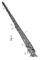
- Figure 2 is a perspective view of a boom section, and
- Figure 3 is a perspective view of the central portion of the boom construction.
- The boom construction 1 has a
central part 20 for mounting the boom construction on a permanent tool bar portion on a tractor or trailer (not shown) provided with the elements necessary for operating a field sprayer, such as described in e.g. international patent application no. WO-95/16347 or Australian patent application no. 14546/83, including pumps and one or more receptacles for spraying agent or water. - The boom construction 1 includes two
boom sections joints 13, 13' and theboom sections central part 20 atjoints 8, whereby theboom sections flexible air hoses 5, 5' and hoses and nozzles for ejecting spraying liquid. - Fig. 2 is a more detailed view of one of the
boom sections 10 and thecentral portion 20. Theboom section 10 carries aseparate air blower 25. Theflexible air hose 5 is cut off at the ends and extends from thecentral portion 20 to theextremity 12 of theboom section 10. Theair blower 25 is mounted near the end of theboom section 10 where it is embedded on thecentral portion 20, but of course it may be located anywhere along the boom section to provide the desired flow conditions inside the air hose. On its underside, theair hose 5 is provided with air outlets which may e.g. be of the type shown in the above-mentioned Australian or international patent applications. - The principle shown in Figure 2 where each of the two
boom sections air blower 25 arranged in the vicinity of thecentral portion 20, may advantageously be applied to field sprayers where it is necessary to be able to oscillate one boom section upwards or downwards in the vertical plane by means of actuators, irrespective of the position of the other boom section. In this situation the boom sections will be connected with thecentral portion 20 via swivel joints that allow pivoting about a horizontal axis. The advantage of using twoseparate air hoses 5 with an associatedair blower 25 is that it enables said pivotal movement of eachboom section
Claims (5)
- A boom construction (1) including i) a central portion (20) for mounting the boom construction (1) on a trailer or a tractor, ii) a boom section (10, 15) pivotally connected with each side of said central portion (20) and adapted to extend from said side, iii) hoses and nozzles for a spraying liquid, iv) elongated air hose means having air outlets arranged along its underside, and v) means for generating and supplying air to said air hose means,
characterised in that the elongated air hose means includes a first elongated flexible air hose (5) that extends from the area of the central portion (20) to the opposite extremity (12) of one of said boom sections (10), and which is separate from a second elongated flexible air hose (5') extending along the other boom section (15), and in that each boom section (10, 15) carries a single air blower (25, 25') for providing desired flow conditions within the air hose (5, 5') associated with that boom section (10, 15). - A boom construction according to claim 1, characterised in that the boom sections (10, 15) comprise subsections connected at joints (13, 13'), said boom sections being collapsible.
- A boom construction according to any of the preceding claims, characterised in that the air blower (5) is arranged in the vicinity of the central portion (20) of the boom construction (1).
- A boom construction according to any of the preceding claims, characterised in that the air hose (5) tapers towards the end thereof remote from the air blower (25) supplying air thereto.
- A boom construction according to the preceding claim, characterised in that the air hose (5) includes two subsections tapering towards a respective end (12) of the air hose (5).
Applications Claiming Priority (3)
| Application Number | Priority Date | Filing Date | Title |
|---|---|---|---|
| DK040696A DK40696A (en) | 1996-04-10 | 1996-04-10 | agricultural implement |
| DK40696 | 1996-04-10 | ||
| EP97917282A EP0892598B1 (en) | 1996-04-10 | 1997-04-09 | A field sprayer |
Related Parent Applications (1)
| Application Number | Title | Priority Date | Filing Date |
|---|---|---|---|
| EP97917282A Division EP0892598B1 (en) | 1996-04-10 | 1997-04-09 | A field sprayer |
Publications (3)
| Publication Number | Publication Date |
|---|---|
| EP1163847A2 EP1163847A2 (en) | 2001-12-19 |
| EP1163847A3 EP1163847A3 (en) | 2003-01-08 |
| EP1163847B1 true EP1163847B1 (en) | 2006-08-23 |
Family
ID=8093164
Family Applications (2)
| Application Number | Title | Priority Date | Filing Date |
|---|---|---|---|
| EP01203074A Expired - Lifetime EP1163847B1 (en) | 1996-04-10 | 1997-04-09 | A field sprayer |
| EP97917282A Expired - Lifetime EP0892598B1 (en) | 1996-04-10 | 1997-04-09 | A field sprayer |
Family Applications After (1)
| Application Number | Title | Priority Date | Filing Date |
|---|---|---|---|
| EP97917282A Expired - Lifetime EP0892598B1 (en) | 1996-04-10 | 1997-04-09 | A field sprayer |
Country Status (6)
| Country | Link |
|---|---|
| US (1) | US6131821A (en) |
| EP (2) | EP1163847B1 (en) |
| AU (1) | AU716370B2 (en) |
| DE (2) | DE69713580T2 (en) |
| DK (1) | DK40696A (en) |
| WO (1) | WO1997037533A1 (en) |
Cited By (1)
| Publication number | Priority date | Publication date | Assignee | Title |
|---|---|---|---|---|
| US9140398B2 (en) | 2010-04-02 | 2015-09-22 | Pentair Flow Technologies, Llc | Air aspiration device |
Families Citing this family (20)
| Publication number | Priority date | Publication date | Assignee | Title |
|---|---|---|---|---|
| US9049854B2 (en) * | 2002-11-07 | 2015-06-09 | Mark Ellsworth | Crop spraying vehicle |
| US20040195356A1 (en) * | 2002-11-07 | 2004-10-07 | Mark Ellsworth | Crop spraying device |
| US6834223B2 (en) | 2003-02-10 | 2004-12-21 | Norac Systems International, Inc. | Roll control system and method for a suspended boom |
| US7021396B2 (en) * | 2003-09-05 | 2006-04-04 | Wil-Rich, Llc | Suspension system for a three-point apparatus |
| USD559274S1 (en) * | 2007-02-20 | 2008-01-08 | Cnh Canada, Ltd. | Sprayer boom structure |
| USD559275S1 (en) * | 2007-02-21 | 2008-01-08 | Cnh Canada, Ltd. | Sprayer center frame |
| USD559276S1 (en) * | 2007-03-05 | 2008-01-08 | Cnh Canada, Ltd. | Sprayer plumbing layout |
| RU2519785C2 (en) * | 2010-08-20 | 2014-06-20 | Александр Николаевич Зенков | Suspension for dual console distribution rod |
| US8827180B2 (en) | 2011-04-29 | 2014-09-09 | Cnh Industrial America Llc | Agricultural sprayer boom having aligned mast and center section |
| EP3308643B2 (en) | 2013-09-18 | 2024-06-19 | HORSCH LEEB Application Systems GmbH | Device for dispensing fluid and/or solid agents and method for controlling the device |
| WO2015067804A1 (en) | 2013-11-10 | 2015-05-14 | Horsch Leeb Application Systems Gmbh | Apparatus for discharging liquid and/or solid active substances and method for controlling such an apparatus |
| US9462799B2 (en) * | 2013-12-18 | 2016-10-11 | Agco Corporation | Pivot hinge boom spray system |
| CN103891696B (en) * | 2014-03-26 | 2015-08-19 | 山东省农业机械科学研究院 | Intelligent accurate boom sprayer and control method |
| DE102015102975A1 (en) | 2015-03-02 | 2016-09-08 | Horsch Leeb Application Systems Gmbh | Device for dispensing liquid and / or solid active substances and method for controlling such a device |
| USD753729S1 (en) * | 2015-03-09 | 2016-04-12 | King Marine, S.A. | Boom arm for agricultural sprayer |
| US11241005B2 (en) | 2017-04-28 | 2022-02-08 | Mark S. Ellsworth | Crop spraying vehicle |
| US10278326B2 (en) | 2017-06-05 | 2019-05-07 | Cnh Industrial Canada, Ltd. | Fertilizer application system using pneumatic conveying with large diameter lines and rotary distributor |
| PL239091B1 (en) * | 2019-06-06 | 2021-11-02 | Radon Stanislaw | Sprayer for row crops |
| USD923061S1 (en) * | 2019-10-25 | 2021-06-22 | Horsch Leeb Application Systems Gmbh | Agricultural machine |
| USD1066426S1 (en) * | 2020-10-30 | 2025-03-11 | Deere & Company | Boom truss panel for agricultural machine |
Family Cites Families (8)
| Publication number | Priority date | Publication date | Assignee | Title |
|---|---|---|---|---|
| SE421853B (en) * | 1978-02-13 | 1982-02-08 | Moteska Svenska Ab | DEVICE AT A SPRAYING DEVICE |
| GB2028078B (en) * | 1978-08-22 | 1982-10-06 | British Res Agricult Eng | Boom assemblies |
| FR2520586B1 (en) * | 1982-01-29 | 1985-08-02 | Tecnoma | MOBILE APPARATUS FOR SPRAYING A PLANT TREATMENT LIQUID |
| US4650124A (en) * | 1985-05-14 | 1987-03-17 | Ag Systems, Inc. | Chemical spray applicator |
| GB2191922B (en) * | 1986-06-24 | 1990-07-25 | Nat Res Dev | Boom assemblies |
| US4880160A (en) * | 1988-05-24 | 1989-11-14 | Deere & Company | Torsional link boom suspension for reducing unwanted boom motion |
| US5098018A (en) * | 1990-09-28 | 1992-03-24 | Kibbuts Degania Bet | Crop spray apparatus having independently controlled drive assembly, operator's cab and spray device |
| DK139693D0 (en) * | 1993-12-17 | 1993-12-17 | Hardi Int As | AIR CONDITION FOR AN AGRICULTURAL SPRAY |
-
1996
- 1996-04-10 DK DK040696A patent/DK40696A/en unknown
-
1997
- 1997-04-09 DE DE69713580T patent/DE69713580T2/en not_active Expired - Lifetime
- 1997-04-09 WO PCT/DK1997/000151 patent/WO1997037533A1/en not_active Ceased
- 1997-04-09 US US09/155,874 patent/US6131821A/en not_active Expired - Lifetime
- 1997-04-09 EP EP01203074A patent/EP1163847B1/en not_active Expired - Lifetime
- 1997-04-09 AU AU25680/97A patent/AU716370B2/en not_active Ceased
- 1997-04-09 DE DE69736569T patent/DE69736569T2/en not_active Expired - Lifetime
- 1997-04-09 EP EP97917282A patent/EP0892598B1/en not_active Expired - Lifetime
Cited By (1)
| Publication number | Priority date | Publication date | Assignee | Title |
|---|---|---|---|---|
| US9140398B2 (en) | 2010-04-02 | 2015-09-22 | Pentair Flow Technologies, Llc | Air aspiration device |
Also Published As
| Publication number | Publication date |
|---|---|
| DE69736569D1 (en) | 2006-10-05 |
| EP0892598A1 (en) | 1999-01-27 |
| DK40696A (en) | 1997-10-11 |
| DE69713580D1 (en) | 2002-08-01 |
| WO1997037533A1 (en) | 1997-10-16 |
| EP1163847A2 (en) | 2001-12-19 |
| AU2568097A (en) | 1997-10-29 |
| US6131821A (en) | 2000-10-17 |
| DE69736569T2 (en) | 2007-08-16 |
| DE69713580T2 (en) | 2002-11-07 |
| EP1163847A3 (en) | 2003-01-08 |
| EP0892598B1 (en) | 2002-06-26 |
| AU716370B2 (en) | 2000-02-24 |
Similar Documents
| Publication | Publication Date | Title |
|---|---|---|
| EP1163847A2 (en) | A field sprayer | |
| US5176322A (en) | Crop-spraying apparatus | |
| CA1206126A (en) | Covered field sprayers | |
| US5062572A (en) | Spray shield | |
| SK75996A3 (en) | An agricultural sprayer unit and an air-flow generating assembly of an agricultural sprayer unit | |
| EP1380248A3 (en) | Cleaning implement having a sprayer nozzle attached to a cleaning head member | |
| US6036121A (en) | Method of varying the speed of a center pivot irrigation system | |
| US6036122A (en) | Corner irrigation system | |
| WO1988001539A1 (en) | Crop-spraying apparatus | |
| JP4633566B2 (en) | Irrigation device for passenger management machine and passenger management machine | |
| US6116527A (en) | Center-pivot irrigation rut prevention device | |
| EP3704939B1 (en) | Drop-down applicators for an agricultural sprayer | |
| US4429831A (en) | Ground release irrigation system | |
| US6029914A (en) | Corner irrigation system | |
| US12538914B2 (en) | Spray device for spraying liquid on crops | |
| EP0841006B1 (en) | Apparatus and method for applying liquid such as pesticides to the land | |
| KR200231396Y1 (en) | Spraying apparatus | |
| KR20110091277A (en) | distributor | |
| JP2507748Y2 (en) | Boom sprayer | |
| JP4150636B2 (en) | Spreading tube fixing structure | |
| JPH0522306Y2 (en) | ||
| JPH0871473A (en) | Water painting fountain | |
| CN217601891U (en) | Groove cleaning device | |
| KR200226700Y1 (en) | A cropdusting system for greenhouse | |
| JP2984096B2 (en) | Spray port support structure |
Legal Events
| Date | Code | Title | Description |
|---|---|---|---|
| PUAI | Public reference made under article 153(3) epc to a published international application that has entered the european phase |
Free format text: ORIGINAL CODE: 0009012 |
|
| AC | Divisional application: reference to earlier application |
Ref document number: 892598 Country of ref document: EP |
|
| AK | Designated contracting states |
Kind code of ref document: A2 Designated state(s): DE ES FR GB IT NL |
|
| RIN1 | Information on inventor provided before grant (corrected) |
Inventor name: NEJSUM, LARS |
|
| PUAL | Search report despatched |
Free format text: ORIGINAL CODE: 0009013 |
|
| AK | Designated contracting states |
Kind code of ref document: A3 Designated state(s): DE ES FR GB IT NL |
|
| 17P | Request for examination filed |
Effective date: 20030701 |
|
| AKX | Designation fees paid |
Designated state(s): DE ES FR GB IT NL |
|
| 17Q | First examination report despatched |
Effective date: 20050407 |
|
| GRAP | Despatch of communication of intention to grant a patent |
Free format text: ORIGINAL CODE: EPIDOSNIGR1 |
|
| GRAS | Grant fee paid |
Free format text: ORIGINAL CODE: EPIDOSNIGR3 |
|
| GRAA | (expected) grant |
Free format text: ORIGINAL CODE: 0009210 |
|
| AC | Divisional application: reference to earlier application |
Ref document number: 0892598 Country of ref document: EP Kind code of ref document: P |
|
| AK | Designated contracting states |
Kind code of ref document: B1 Designated state(s): DE ES FR GB IT NL |
|
| PG25 | Lapsed in a contracting state [announced via postgrant information from national office to epo] |
Ref country code: IT Free format text: LAPSE BECAUSE OF FAILURE TO SUBMIT A TRANSLATION OF THE DESCRIPTION OR TO PAY THE FEE WITHIN THE PRESCRIBED TIME-LIMIT;WARNING: LAPSES OF ITALIAN PATENTS WITH EFFECTIVE DATE BEFORE 2007 MAY HAVE OCCURRED AT ANY TIME BEFORE 2007. THE CORRECT EFFECTIVE DATE MAY BE DIFFERENT FROM THE ONE RECORDED. Effective date: 20060823 Ref country code: NL Free format text: LAPSE BECAUSE OF FAILURE TO SUBMIT A TRANSLATION OF THE DESCRIPTION OR TO PAY THE FEE WITHIN THE PRESCRIBED TIME-LIMIT Effective date: 20060823 |
|
| REG | Reference to a national code |
Ref country code: GB Ref legal event code: FG4D |
|
| REF | Corresponds to: |
Ref document number: 69736569 Country of ref document: DE Date of ref document: 20061005 Kind code of ref document: P |
|
| PG25 | Lapsed in a contracting state [announced via postgrant information from national office to epo] |
Ref country code: ES Free format text: LAPSE BECAUSE OF FAILURE TO SUBMIT A TRANSLATION OF THE DESCRIPTION OR TO PAY THE FEE WITHIN THE PRESCRIBED TIME-LIMIT Effective date: 20061204 |
|
| NLV1 | Nl: lapsed or annulled due to failure to fulfill the requirements of art. 29p and 29m of the patents act | ||
| ET | Fr: translation filed | ||
| PLBE | No opposition filed within time limit |
Free format text: ORIGINAL CODE: 0009261 |
|
| STAA | Information on the status of an ep patent application or granted ep patent |
Free format text: STATUS: NO OPPOSITION FILED WITHIN TIME LIMIT |
|
| 26N | No opposition filed |
Effective date: 20070524 |
|
| GBPC | Gb: european patent ceased through non-payment of renewal fee |
Effective date: 20070409 |
|
| PG25 | Lapsed in a contracting state [announced via postgrant information from national office to epo] |
Ref country code: GB Free format text: LAPSE BECAUSE OF NON-PAYMENT OF DUE FEES Effective date: 20070409 |
|
| REG | Reference to a national code |
Ref country code: FR Ref legal event code: PLFP Year of fee payment: 19 |
|
| PGFP | Annual fee paid to national office [announced via postgrant information from national office to epo] |
Ref country code: DE Payment date: 20151030 Year of fee payment: 19 |
|
| PGFP | Annual fee paid to national office [announced via postgrant information from national office to epo] |
Ref country code: FR Payment date: 20151027 Year of fee payment: 19 |
|
| REG | Reference to a national code |
Ref country code: DE Ref legal event code: R119 Ref document number: 69736569 Country of ref document: DE |
|
| REG | Reference to a national code |
Ref country code: FR Ref legal event code: ST Effective date: 20161230 |
|
| PG25 | Lapsed in a contracting state [announced via postgrant information from national office to epo] |
Ref country code: FR Free format text: LAPSE BECAUSE OF NON-PAYMENT OF DUE FEES Effective date: 20160502 Ref country code: DE Free format text: LAPSE BECAUSE OF NON-PAYMENT OF DUE FEES Effective date: 20161101 |