EP1163508B1 - Device for inspecting flat goods made of polymeric materials with embedded textile strength supports - Google Patents
Device for inspecting flat goods made of polymeric materials with embedded textile strength supports Download PDFInfo
- Publication number
- EP1163508B1 EP1163508B1 EP00943825A EP00943825A EP1163508B1 EP 1163508 B1 EP1163508 B1 EP 1163508B1 EP 00943825 A EP00943825 A EP 00943825A EP 00943825 A EP00943825 A EP 00943825A EP 1163508 B1 EP1163508 B1 EP 1163508B1
- Authority
- EP
- European Patent Office
- Prior art keywords
- nmr
- measurement
- flat goods
- probe
- mouse
- Prior art date
- Legal status (The legal status is an assumption and is not a legal conclusion. Google has not performed a legal analysis and makes no representation as to the accuracy of the status listed.)
- Expired - Lifetime
Links
- 239000000463 material Substances 0.000 title claims abstract description 55
- 239000004753 textile Substances 0.000 title claims description 17
- 238000004458 analytical method Methods 0.000 claims abstract description 10
- 238000005259 measurement Methods 0.000 claims description 47
- 239000000523 sample Substances 0.000 abstract description 93
- 230000002787 reinforcement Effects 0.000 abstract description 17
- 238000013421 nuclear magnetic resonance imaging Methods 0.000 abstract 1
- 230000010287 polarization Effects 0.000 description 9
- 239000002861 polymer material Substances 0.000 description 9
- 239000000835 fiber Substances 0.000 description 6
- 238000005160 1H NMR spectroscopy Methods 0.000 description 5
- 229920001971 elastomer Polymers 0.000 description 4
- 239000004744 fabric Substances 0.000 description 4
- 238000005481 NMR spectroscopy Methods 0.000 description 3
- 239000004952 Polyamide Substances 0.000 description 3
- 239000000806 elastomer Substances 0.000 description 3
- 238000011835 investigation Methods 0.000 description 3
- 229920002647 polyamide Polymers 0.000 description 3
- 230000035945 sensitivity Effects 0.000 description 3
- 238000012360 testing method Methods 0.000 description 3
- 230000007547 defect Effects 0.000 description 2
- 230000001066 destructive effect Effects 0.000 description 2
- 238000003384 imaging method Methods 0.000 description 2
- 238000000034 method Methods 0.000 description 2
- 238000011160 research Methods 0.000 description 2
- 230000011664 signaling Effects 0.000 description 2
- 238000004293 19F NMR spectroscopy Methods 0.000 description 1
- 229920000049 Carbon (fiber) Polymers 0.000 description 1
- 229920000742 Cotton Polymers 0.000 description 1
- 239000004372 Polyvinyl alcohol Substances 0.000 description 1
- 239000004760 aramid Substances 0.000 description 1
- 229920006231 aramid fiber Polymers 0.000 description 1
- 230000033228 biological regulation Effects 0.000 description 1
- 239000004917 carbon fiber Substances 0.000 description 1
- 229920002678 cellulose Polymers 0.000 description 1
- 239000001913 cellulose Substances 0.000 description 1
- 238000012512 characterization method Methods 0.000 description 1
- 230000001419 dependent effect Effects 0.000 description 1
- 238000013461 design Methods 0.000 description 1
- 238000001514 detection method Methods 0.000 description 1
- 239000013536 elastomeric material Substances 0.000 description 1
- 238000005516 engineering process Methods 0.000 description 1
- 230000005284 excitation Effects 0.000 description 1
- 239000003365 glass fiber Substances 0.000 description 1
- 125000004435 hydrogen atom Chemical class [H]* 0.000 description 1
- 238000004519 manufacturing process Methods 0.000 description 1
- 238000013507 mapping Methods 0.000 description 1
- 239000012528 membrane Substances 0.000 description 1
- 239000002557 mineral fiber Substances 0.000 description 1
- 229920003052 natural elastomer Polymers 0.000 description 1
- 229920001194 natural rubber Polymers 0.000 description 1
- 229920000728 polyester Polymers 0.000 description 1
- 229920000642 polymer Polymers 0.000 description 1
- 229920002451 polyvinyl alcohol Polymers 0.000 description 1
- 238000007639 printing Methods 0.000 description 1
- 239000005060 rubber Substances 0.000 description 1
- 238000007493 shaping process Methods 0.000 description 1
- 230000003068 static effect Effects 0.000 description 1
- 238000005728 strengthening Methods 0.000 description 1
- 229920003051 synthetic elastomer Polymers 0.000 description 1
- 239000012209 synthetic fiber Substances 0.000 description 1
- 229920002994 synthetic fiber Polymers 0.000 description 1
- 239000005061 synthetic rubber Substances 0.000 description 1
- 229920001169 thermoplastic Polymers 0.000 description 1
- 229920002725 thermoplastic elastomer Polymers 0.000 description 1
- 229920001187 thermosetting polymer Polymers 0.000 description 1
- 239000004416 thermosoftening plastic Substances 0.000 description 1
- 238000004073 vulcanization Methods 0.000 description 1
Images


Classifications
-
- G—PHYSICS
- G01—MEASURING; TESTING
- G01R—MEASURING ELECTRIC VARIABLES; MEASURING MAGNETIC VARIABLES
- G01R33/00—Arrangements or instruments for measuring magnetic variables
- G01R33/20—Arrangements or instruments for measuring magnetic variables involving magnetic resonance
- G01R33/28—Details of apparatus provided for in groups G01R33/44 - G01R33/64
-
- G—PHYSICS
- G01—MEASURING; TESTING
- G01N—INVESTIGATING OR ANALYSING MATERIALS BY DETERMINING THEIR CHEMICAL OR PHYSICAL PROPERTIES
- G01N24/00—Investigating or analyzing materials by the use of nuclear magnetic resonance, electron paramagnetic resonance or other spin effects
- G01N24/08—Investigating or analyzing materials by the use of nuclear magnetic resonance, electron paramagnetic resonance or other spin effects by using nuclear magnetic resonance
- G01N24/085—Analysis of materials for the purpose of controlling industrial production systems
Definitions
- the invention relates to a device for examining flat goods made of polymeric materials with embedded textile reinforcements.
- Sheets made of polymeric materials with textile reinforcements that are used for Reinforcement and shaping are embedded in the polymer material is known.
- Sheeting made from such polymeric materials, the elastomers, thermoplastic elastomers, thermoplastics and thermosets include serve especially for use in roof coverings, as printing blankets, conveyor belts, Membranes as well as cylindrical sheets in air springs, hoses and Compensators.
- the object of the invention is to provide a device with which the Flat goods as completely as possible with regard to the arrangement and course of the Strength members in the polymeric material can be examined non-destructively. In particular, unwanted defects, e.g. unequal distances of the Strength members or missing strength members can be determined. there the quality of the surface goods should not be due to the examination method be affected.
- the device should have a simple structure with good Work contrast.
- NMR MOUSE probes (Nuclear Magnetic Resonance MObile Universal Surface Explorer) are known for material analysis in materials research, see G. Eidmann et al, "The NMR-MOUSE, a Mobile Universal Surface Explorer," Journal of Magnetic Resonance (J.Magn.Res.) A122, 1996, pp. 104/109, and A. Guthausen et al, "Analysis of Polymer Materials by Surface NMR via the MOUSE", J.Magn.Reson. A129, 1997, p.001 / 007, and A. Guthausen et al, "NMR imaging and materials research ", Chemistry of our time, 1998, p.73 / 82.
- NMR-MOUSE probes is determined by magnetic resonance (NMR) in one of the surface of the An NMR signal is generated and measured in the vicinity of the probe Characterization of the properties of the near-surface area of the NMR-MOUSE probe arranged materials is exploited polymeric materials with textile reinforcements exist in the sense of practically feasible measurement of the nuclear magnetic resonance of the Hydrogen nucleus 1H (1H-NMR) from signaling areas, namely the polymeric material, and a material that - like the textile reinforcement - little to no signal. To examine the position of the textile Strength in the polymeric material is therefore already the usual one experimental conditions less demanding mapping of the spin density sufficient. An introduction of relaxation contrast is to evaluate the Test results are not necessarily required, but neither disturbing.
- the core 19F may also be used for area products with NMR MOUSE probes. Lies 19F only in the material of the textile reinforcement, so the textile Strength members can be imaged directly by 19F-NMR.
- the analysis of the flat goods made of polymer material with textiles Strength beams with NMR MOUSE probes are particularly advantageous because 1) the Sensitivity of measurement of the NMR MOUSE probes at shallow depths sensitive volume of the probe (e.g. 0 to 3 mm) is particularly high and 2) soft matter such as polymers is particularly suitable for NMR imaging. If one dispenses with a homogeneous magnetic polarization field B0 and homogeneous high-frequency field B1, the NMR-MOUSE probes can in the ratio to be built small compared to conventional NMR devices.
- the NMR MOUSE probes arranged in the measuring plane mutually overlapping to the Examine surface goods as extensively as possible in one direction in the material can, especially in such a way that their sensitive volume ranges in overlap this direction, claim 3.
- the measurement can be carried out at an elevated temperature at which the rubber molecules move more thermally.
- the surface goods are examined warm.
- the examination can take place during and / or immediately after the production process, the vulcanization.
- the examination temperature is limited by the Curie temperature of the material, the temperature of the fabric must be below the Curie temperature.
- the gain in measurement sensitivity associated with this measurement can be offset by a loss of contrast due to the different NMR relaxation times, but an increase in the measurement sensitivity is of greater importance for the area product to be examined here.
- Figures 1 and 2 show devices for examining flat goods polymeric material with measuring bodies 1 and 2, the NMR MOUSE probes exhibit.
- the devices are used for Examination of a pneumatically resilient component made of natural or synthetic rubber, which to increase its resilience textile Strength members are attached.
- the textile reinforcements in the polymer material consist of aramid fibers or polyamide fibers in the exemplary embodiments. Polyester, mineral fibers (e.g. glass fiber), carbon fibers, fibers are also suitable from acetylated polyvinyl alcohol, reon fibers (semi-synthetic fibers e.g. with Cellulose) or, for example, cotton.
- embedded strength members are fibers made of one material, compared to the polymeric base material in which they are embedded, one has lower 1H or 19F density or the other NMR relaxation times having.
- the measuring body 1 which is cylindrical in shape, is particularly for testing tubular fabric 3 determined, with the measuring body 2 are flat Material webs 4 can be examined as flat goods.
- the polymeric material is traversed by reinforcements 7, the location of which in the area product 3 or 4 is shown only schematically in the drawing.
- the strength members 7 pass through the polymer Material at a distance 8 substantially parallel to each other in a predetermined Direction, in the exemplary embodiment parallel to the longitudinal extension of the hose or sheet-like flat goods 3 or 4.
- the distance 8 between the parallel extending strength members 7 is approximately 0.5 to 1 mm.
- the strength members embedded in the material can also be used in others Be arranged as shown in Figures 1 and 2, for example the material Pull through like a net or cross each other.
- An NMR MOUSE probe shows the polarization of the nuclear magnetic moments in the material to be examined and for generating measurement signals spatially inhomogeneous magnetic fields.
- Figure 3 are at an NMR MOUSE probe 9 between two oppositely magnetized Permanent magnets 10, 11 with permanent magnet poles N and S two Gradient coils 12, 13 and one between the gradient coils High-frequency coil 14.
- the static polarization field B0 which between the Permanent magnet poles is generated by means of the high-frequency coil 14 in time interval pulsating a magnetic measuring field B1 as a magnetic Share of a radio frequency field superimposed with the radio frequency coil as Part of an electrical resonant circuit is formed and received.
- Pulse of the magnetic measuring field B1 is understood to mean that the magnetic field in a predetermined timing by exciting the high frequency coil over a short period is generated intermittently. With the gradient coils 12, 13, also pulsed - the magnetic field additionally a magnetic gradient field BG superimposed.
- the field lines of the gradient field BG are schematic in FIG. 3a entered. Shape and size of the surrounding volume that is in the outer Environment of the NMR MOUSE probe implied nuclear magnetic and by measurement of the echo signals is to be detected and the measurement-sensitive volume range represents for each probe on the one hand due to the specific bandwidth of the magnetic high-frequency excitation and on the other hand by the orthogonal Components of both magnetic fields B0 and B1 defined.
- the course of the magnetic field lines and thus the size of the signaling Volume range can be dimensioned and arranged accordingly Permanent magnets and the coil of the high-frequency electrical resonant circuit to be changed.
- the permanent magnetic polarization field B0 (basic field) is created using the Gradient coils 12, 13 thus additionally have a gradient field BG with a Field gradients tangential to the outer surface of the NMR-MOUSE probe 9 and generated perpendicular to the polarization field B0.
- This additional field BG becomes Generation of the spatial resolution (phase coding of the spatial information) in time Distance pulsed.
- the high-frequency coil 14 is arranged in such a way that the Field lines of the polarization field B0 and the field lines of the by High-frequency coil generated magnetic measuring field B1 in the measurement-sensitive Volume area are perpendicular to each other.
- the orthogonal components of the Both magnetic fields B0 and B1 indicate the measurement signal. For suggestion and The same high-frequency coil is used to detect the measurement signal.
- Adjacent permanent magnet rings 17a, 17b are polarized in opposite directions: this is in addition to the permanent magnet ring 17a, whose magnetic field radially from the outside in the magnetic north / south direction Is directed inside (the magnetic north pole N of the permanent magnet ring 17a is formed by the outer ring surface), at a distance of 18 Permanent magnet ring 17b attached with the opposite magnetic field (The outer ring surface of the permanent magnet ring 17b forms the magnetic South Pole S).
- 16 on the cylindrical measuring body 1 between adjacent permanent magnet rings 17 on the cylinder surface 5 toroidally rotationally symmetrical Permanent magnetic fields B0 generated with which on the cylinder surface of the Measuring body lying material can be penetrated.
- the permanent magnet ring field B0 is the Permanent magnet rings a pulsed magnetic measuring field B1 as a magnetic Share of a high-frequency field can be superimposed, with the gradient coils 19 also pulsed - additionally in the measuring-sensitive volume range Gradient field BG in the tangential direction to the cylinder surface 5 and perpendicular to the permanent magnet ring field B0.
- the Gradient coils can be the permanent magnetic field B0 with the Gradient coils maximally influence the generated gradient fields BG.
- Each sector areas delimited by adjacent gradient coils 19 Permanent magnet rings 17 form together with these gradient coils and between the gradient coils 19 used high-frequency coil 20 an NMR MOUSE probe. Each gradient coil is therefore two to each other assigned to adjacent NMR MOUSE probes.
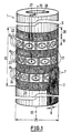
- FIG. 1 In the embodiment of Figure 1 are in the measuring plane on the cylindrical Measuring body 1 four permanent magnet rings 17 in the axial direction of the cylinder axis 15 arranged sequentially. On the cylinder surface 5 of the measuring body 1 are thus in the measuring range 16 from the radially polarized permanent magnet rings 17 each with opposite magnetic field direction Permanent magnet rings three toroidal, rotationally symmetrical polarization fields B0 generated. Between the permanent magnet rings 17 are three probe rings 22, 23, 24 provided with gradient and high-frequency coils 19 and 20, respectively.
- Figure 1 are the NMR MOUSE probes that work in this way on each probe ring be formed and adjacent to each ring perpendicular to the course of the Strength members are arranged with reference number 9a for the NMR MOUSE probes in the probe ring 22, with reference number 9b for the NMR MOUSE probes in the Probe ring 23 and 9c for the NMR MOUSE probes in the Probe ring 24 specified.
- the shape and size of the measuring body 1 is the Dimensions of the surface product to be examined in the application adapted.
- the NMR MOUSE probes are designed in such a way that surface goods can be examined is, the textile reinforcements are at least about 0.1 mm thick and in one Depth between about 0.2 to 5 mm below the surface in the polymer material are embedded.
- a pneumatically resilient, tubular elastomer covering which has a thickness of 2 mm, with Strengtheners made of 0.2 to 0.5 mm thick polyamide fibers examined that the polymeric material in the middle at a depth of 1 mm in the longitudinal extension of the Pull the hose parallel to each other at a distance of 0.5 to 1 mm.
- the Diameter 25 of the measuring body 1 with the permanent magnet rings 17 is adapted to the hose diameter 80 mm.
- the ring thickness 26 of the Permanent magnet rings parallel to the cylinder axis 15 is 20 mm, the distance 18 between the permanent magnet rings 17 for receiving the gradient and High-frequency coils 19 and 20 are 13 mm long. Overall are on the scope of the measuring body 1 in the exemplary embodiment per ring 22 to 24 12 NMR MOUSE probes distributed.
- the NMR MOUSE probes 9a, 9b, 9c are on the measuring body 1 in the ring planes of the three probe rings 22 to 24 viewed in the direction of the cylinder axis 15 Probe ring 22 to the probe ring 24 in each case at an angle 27 to one another staggered so that the measurement-sensitive volume ranges of the NMR MOUSE probes 9a, 9b, 9c overlap with the target, the tubular one Material in the measuring range 16 if possible over the entire circumference of the hose scan.
- the parallel course of the textile reinforcement in the polymer Material can be completely captured in this way.
- the polymeric material with the textile reinforcements exists in the sense of NMR analysis regarding the concentration of the magnetic magnet to be determined core 1H to be polarized, on the one hand, from such material areas that a strong NMR signal (due to strong 1 H or 19F density or longer transversal relaxation time), namely the areas that only consist of consist of polymeric material, in the exemplary embodiment of elastomeric material, and on the other hand from such material areas, of which little to none Signals go out, namely areas in which in the elastomer textile Strength members run, in the exemplary embodiment polyamide fibers.
- the relevant one measurement-sensitive volume range of an NMR MOUSE probe on a Core area is limited, which is smaller than the space of one NMR MOUSE probe on a probe ring between two gradient coils 19 is taken.
- Figure 4 are in the measurement protocols as characteristic Size for the measurement-sensitive volume ranges 35, 36, 37 of the three NMR-MOUSE probes 9a, 9b, 9c that can be evaluated for the analysis of the flat goods Intervals entered and with the reference numbers of the volume ranges characterized. Outside of these measurement-sensitive volume areas 35, 36, 37 remain with the NMR MOUSE probes due to their technical structure Dead spaces that cannot be used for the measurement.
- these dead spaces of the individual NMR MOUSE probes by mutually displacing the probes from the probe ring Bridged probe ring.
- the NMR MOUSE probes are in a probe ring compared to the NMR MOUSE probes in an adjacent probe ring arranged angularly offset, in the embodiment by the angle 27 such offset that at least the outermost strength member, that of the sensitive Volume range of an NMR MOUSE probe is just recorded, even in the measurement-sensitive volume range of the staggered NMR MOUSE probe falls in the neighboring probe ring.
- the NMR MOUSE probes 9b and 9c in the Probe rings 23 and 24 against each other with respect to the strength member 30b staggered the strength member 30b is both in the edge region of the measurement-sensitive volume area 36 as well as in the edge area of the measurement-sensitive volume range 37 measured.
- the NMR MOUSE probes have the same design Dimension angle 27 to move the probes the same size.
- angle 27 for the overlap of the NMR MOUSE probes can also be smaller be chosen as specified in the embodiment. At a smaller angle are then, to be on the safe side, offset from each other NMR MOUSE probes several strength members in the edge area of the measurement-sensitive volume range measured overlapping.
- the NMR MOUSE probes are designed to be alternately controllable, so that after each measurement with one of the NMR MOUSE probes during the ratio Long signal build-up time at measurement time (signal build-up time approx. 25 ms, measurement time approx. 300 ⁇ s) most of the device hardware that is used to control the gradient and high-frequency coils is needed to accommodate another Data point with another one of the NMR MOUSE probes can. This shortens the total required for the analysis of the material Examination time. Fast switches are required for this, not only for Switch between sending and receiving on one probe, but also for Switching between the probes are suitable.
- each opens at the center of a high-frequency coil 20 Mouths 38a of an air duct 38 which runs centrally in the measuring body 1 and which Overpressure and underpressure can be applied.
- the tubular sheet 3 which on the Cylinder surface 5 of the measuring body 1 rests and the cylinder surface encloses, drawn by negative pressure on the cylindrical measuring plane, the The surface goods are transported at overpressure and from Cylinder surface of loosened surface goods.
- the measuring body 2 shown in detail in FIG. 2 for flat material webs 4 is designed analogously to the measuring body 1. Instead of a cylindrical measuring plane here a flat measuring plane 6 is provided, which is at a distance 39 from one another arranged block-shaped permanent magnets 40 with flat pole faces N or S is formed. High frequency and are between the permanent magnets 40 Gradient coils 41, 42 are used.
- the measuring body 2 has four opposite polarized permanent magnet blocks 40 with three probe zones 43, 44, 45 on, in which the NMR-MOUSE probes are again arranged so offset are that the structure of the planes to be examined as flat goods 4 Material webs in the measuring area of the measuring body 2 is completely detectable.
- the permanent magnets used in the exemplary embodiments for generation the polarization fields B0 can be by electromagnets or replace superconducting or high temperature superconducting magnets.
- the Gradient coils used allow for that on the measuring bodies surface goods lying in the exemplary embodiments are one-dimensional Spatial resolution in the tangential direction on the measurement planes. With others Gradient coils can expand the measurement to two-dimensional spatial resolution become.
Abstract
Description
Die Erfindung bezieht sich auf eine Vorrichtung zur Untersuchung von Flächenware aus polymeren Werkstoffen mit eingebetteten textilen Festigkeitsträgern.The invention relates to a device for examining flat goods made of polymeric materials with embedded textile reinforcements.
Flächenware aus polymeren Werkstoffen mit textilen Festigkeitsträgern, die zur Verstärkung und Formgebung im polymeren Werkstoff eingebettet sind, ist bekannt. Flächenware aus solchen polymeren Werkstoffen, die Elastomere, thermoplastische Elastomere, Thermoplaste und Duroplaste umfassen, dienen insbesondere zum Einsatz in Dachbelägen, als Drucktücher, Fördergurte, Membranen sowie als zylindrische Flächenware in Luftfedern, Schläuchen und Kompensatoren.Sheets made of polymeric materials with textile reinforcements that are used for Reinforcement and shaping are embedded in the polymer material is known. Sheeting made from such polymeric materials, the elastomers, thermoplastic elastomers, thermoplastics and thermosets include serve especially for use in roof coverings, as printing blankets, conveyor belts, Membranes as well as cylindrical sheets in air springs, hoses and Compensators.
Von Bedeutung sind Qualitätsbestimmungen für die Flächenware, vor allem Untersuchungen, mit denen der Verlauf der Festigkeitsträger im polymeren Werkstoff festgestellt werden kann. Bisher werden die Werkstoffe in folgender Weise untersucht: Zerstörende stochastische Untersuchungsmethoden, zerstörungsfrei mittels Röntgendurchstrahlungstechnik.Quality regulations for surface goods are of particular importance Investigations with which the course of the reinforcement in the polymer Material can be determined. So far, the materials in the following Wisely examined: Destructive stochastic methods of investigation, non-destructive using X-ray technology.
Aufgabe der Erfindung ist es, eine Vorrichtung zur Verfügung zu stellen, mit der die Flächenware möglichst vollständig hinsichtlich Anordnung und Verlauf der Festigkeitsträger im polymeren Werkstoff zerstörungsfrei untersuchbar ist. Insbesondere sollen nicht gewünschte Störstellen, z.B. ungleiche Abstände der Festigkeitsträger oder fehlende Festigkeitsträger, ermittelt werden können. Dabei soll durch die Untersuchungsmethode die Qualität der Flächenware nicht beeinträchtigt werden. Die Vorrichtung soll bei einfachem Aufbau mit gutem Kontrast arbeiten.The object of the invention is to provide a device with which the Flat goods as completely as possible with regard to the arrangement and course of the Strength members in the polymeric material can be examined non-destructively. In particular, unwanted defects, e.g. unequal distances of the Strength members or missing strength members can be determined. there the quality of the surface goods should not be due to the examination method be affected. The device should have a simple structure with good Work contrast.
Diese Aufgabe wird gemäß Anspruch 1 durch Ausbildung eines Meßkörpers mit einer von NMR-MOUSE-Sonden gebildeten Meßebene zur Auflage der Flächenware zur kernmagnetischen Analyse gelöst. Zusätzliche Merkmale sind in den abhängigen Ansprüchen definiert.This object is achieved according to claim 1 by forming a measuring body a measuring plane formed by NMR-MOUSE probes for supporting the Surface product for nuclear magnetic analysis solved. Additional characteristics are defined in the dependent claims.
NMR-MOUSE-Sonden (Nuclear Magnetic Resonance MObile Universal Surface Explorer) sind zur Materialanalyse in der Materialforschung bekannt, siehe G.Eidmann et al, "The NMR-MOUSE, a Mobil Universal Surface Explorer", Journal of Magnetic Resonance (J.Magn.Res.) A122, 1996, S. 104/109, sowie A.Guthausen et al, "Analysis of Polymer Materials by Surface NMR via the MOUSE", J.Magn.Reson. A129, 1997, S.001/007, und A.Guthausen et al, "NMR-Bildgebung und Materialforschung", Chemie unserer Zeit, 1998, S.73/82. Mit NMR-MOUSE-Sonden wird durch magnetische Resonanz (NMR) in einem der Oberfläche der Sonde nahen Umgebungsbereich ein NMR-Signal erzeugt und gemessen, das zur Charakterisierung der Eigenschaften von im oberflächennahen Bereich der NMR-MOUSE-Sonde angeordneten Werkstoffen ausgenutzt wird., Flächenware aus polymeren Werkstoffen mit textilen Festigkeitsträgern besteht im Sinne der praktisch durchführbaren Messung der kernmagnetischen Resonanz des Wasserstoffkerns 1H (1H-NMR) aus signalgebenden Bereichen, nämlich dem polymeren Werkstoff, und einem Material, das - wie die textilen Festigkeitsträger - wenig bis kein Signal abgibt. Zur Untersuchung der Position der textilen Festigkeitsträger im polymeren Werkstoff ist daher schon die unter üblichen experimentellen Bedingungen wenig anspruchsvolle Abbildung der Spindichte ausreichend. Ein Einführen von Relaxationskontrast ist zur Auswertung der Untersuchungsergebnisse nicht notwendigerweise erforderlich, aber auch nicht störend.NMR MOUSE probes (Nuclear Magnetic Resonance MObile Universal Surface Explorer) are known for material analysis in materials research, see G. Eidmann et al, "The NMR-MOUSE, a Mobile Universal Surface Explorer," Journal of Magnetic Resonance (J.Magn.Res.) A122, 1996, pp. 104/109, and A. Guthausen et al, "Analysis of Polymer Materials by Surface NMR via the MOUSE", J.Magn.Reson. A129, 1997, p.001 / 007, and A. Guthausen et al, "NMR imaging and materials research ", Chemistry of our time, 1998, p.73 / 82. With NMR-MOUSE probes is determined by magnetic resonance (NMR) in one of the surface of the An NMR signal is generated and measured in the vicinity of the probe Characterization of the properties of the near-surface area of the NMR-MOUSE probe arranged materials is exploited polymeric materials with textile reinforcements exist in the sense of practically feasible measurement of the nuclear magnetic resonance of the Hydrogen nucleus 1H (1H-NMR) from signaling areas, namely the polymeric material, and a material that - like the textile reinforcement - little to no signal. To examine the position of the textile Strength in the polymeric material is therefore already the usual one experimental conditions less demanding mapping of the spin density sufficient. An introduction of relaxation contrast is to evaluate the Test results are not necessarily required, but neither disturbing.
Neben dem üblicherweise gemessenen Kern 1H kommt für die Untersuchung der Flächenware mit NMR-MOUSE-Sonden auch der Kern 19F in Betracht. Liegt 19F nur im Material der textilen Festigkeitsträger vor, so können die textilen Festigkeitsträger durch 19F-NMR direkt abgebildet werden.In addition to the normally measured core 1H, the The core 19F may also be used for area products with NMR MOUSE probes. Lies 19F only in the material of the textile reinforcement, so the textile Strength members can be imaged directly by 19F-NMR.
Die Analyse der Flächenware aus polymerem Werkstoff mit textilen Festigkeitsträgern mit NMR-MOUSE-Sonden ist besonders vorteilhaft, weil 1) die Messempfindlichkeit der NMR-MOUSE-Sonden bei geringen Tiefen des meßempfindlichen Volumens der Sonde (z. B. 0 bis 3 mm) besonders hoch ist und 2) weiche Materie wie Polymere für die NMR-Bildgebung besonders geeignet ist. Verzichtet man auf ein homogenes magnetisches Polarisierungsfeld B0 und ein homogenes Hochfrequenzfeld B1, können die NMR-MOUSE-Sonden im Verhältnis zu üblichen NMR-Geräten klein gebaut werden.The analysis of the flat goods made of polymer material with textiles Strength beams with NMR MOUSE probes are particularly advantageous because 1) the Sensitivity of measurement of the NMR MOUSE probes at shallow depths sensitive volume of the probe (e.g. 0 to 3 mm) is particularly high and 2) soft matter such as polymers is particularly suitable for NMR imaging. If one dispenses with a homogeneous magnetic polarization field B0 and homogeneous high-frequency field B1, the NMR-MOUSE probes can in the ratio to be built small compared to conventional NMR devices.
In weiterer Ausbildung der Erfindung nach Anspruch 2 sind die NMR-MOUSE-Sonden
in der Meßebene sich gegenseitig überlappend angeordnet, um die
Flächenware möglichst umfassend in einer Richtung im Material untersuchen zu
können, insbesondere derart, daß sich ihre meßempfindlichen Volumenbereiche in
dieser Richtung überlappen, Anspruch 3.In a further embodiment of the invention according to
Wird nur die 1H-Dichte abgebildet, so kann die Messung bei erhöhter Temperatur erfolgen, bei der sich die Gummimoleküle thermisch stärker bewegen. Die Flächenware wird hierzu warm untersucht. Die Untersuchung kann noch während und/oder unmittelbar nach dem Herstellungsprozeß, der Vulkanisation, erfolgen. Die Untersuchungstemperatur wird von der Curie-Temperatur des Materials begrenzt, die Temperatur der Flächenware muß unterhalb der Curie-Temperatur liegen. Dem mit dieser Messung verbundenen Gewinn an Messempfindlichkeit kann zwar ein Verlust an Kontrast durch die verschiedenen NMR-Relaxationszeiten gegenüber stehen, eine Erhöhung der Meßempfindlichkeit ist jedoch für die hier zu untersuchende Flächenware von größerer Bedeutung. If only the 1 H density is shown, the measurement can be carried out at an elevated temperature at which the rubber molecules move more thermally. For this purpose, the surface goods are examined warm. The examination can take place during and / or immediately after the production process, the vulcanization. The examination temperature is limited by the Curie temperature of the material, the temperature of the fabric must be below the Curie temperature. The gain in measurement sensitivity associated with this measurement can be offset by a loss of contrast due to the different NMR relaxation times, but an increase in the measurement sensitivity is of greater importance for the area product to be examined here.
Die Erfindung und weitere Ausgestaltungen der Erfindung werden nachfolgend anhand von Ausführungsbeispielen, die in der Zeichnung schematisch wiedergegeben sind, näher erläutert. Die Zeichnung zeigt im einzelnen
- Figur 1
- zylindrischer Meßkörper mit NMR-MOUSE-Sonden
Figur 2- Ausschnitt eines flächigen Meßkörpers mit NMR-MOUSE-Sonden
Figur 3- Aufbau einer NMR-MOUSE-Sonde mit
- Figur 3a:
- Aufsicht auf eine NMR-MOUSE-Sonde aus Richtung a nach Figur 3b,
- Figur 3b:
- Längsschnitt durch die NMR-MOUSE-Sonde gemäß Schnittlinie b nach Figur 3a
- Figur 4
- Meßbeispiel
- Figure 1
- cylindrical measuring body with NMR-MOUSE probes
- Figure 2
- Section of a flat measuring body with NMR-MOUSE probes
- Figure 3
- Setup of an NMR MOUSE probe with
- Figure 3a:
- Top view of an NMR MOUSE probe from direction a according to FIG. 3b,
- Figure 3b:
- Longitudinal section through the NMR-MOUSE probe according to section line b of Figure 3a
- Figure 4
- Measuring example
Figuren 1 und 2 zeigen Vorrichtungen zur Untersuchung von Flächenware aus
polymerem Werkstoff mit Meßkörpern 1 und 2, die NMR-MOUSE-Sonden
aufweisen. In den Ausführungsbeispielen dienen die Vorrichtungen zur
Untersuchung eines pneumatisch belastbaren Bauteils aus natürlichem oder
synthetischem Kautschuk, dem zur Erhöhung seiner Belastbarkeit textile
Festigkeitsträger beigefügt sind. Die textilen Festigkeitsträger im polymeren Material
bestehen in den Ausführungsbeispielen aus Aramidfasem oder Polyamidfasern.
Geeignet sind auch Polyester, Mineralfasern (z.B. Glasfaser), Kohlefasern, Fasern
aus azetylisiertem Polyvinylalkohol, Reonfasern (halbsynthetische Fasern z.B. mit
Zellulose) oder beispielsweise Baumwolle. Bei den im polymeren Material
eingebetteten Festigkeitsträgern handelt es sich um Fasern aus einem Werkstoff,
der gegenüber dem polymeren Grundmaterial, in dem sie eingebettet sind, eine
geringere 1H - oder 19F - Dichte hat oder der andere NMR-Relaxationszeiten
aufweist.Figures 1 and 2 show devices for examining flat goods
polymeric material with measuring
Der Meßkörper 1, der zylindrisch geformt ist, ist insbesondere zum Test
schlauchförmiger Flächenware 3 bestimmt, mit dem Meßkörper 2 sind ebene
Materialbahnen 4 als Flächenware untersuchbar. Zur Untersuchung wird die
Flächenware beim Meßkörper 1 auf dessen Zylinderoberfläche 5 auf eine
zylindrische Meßebene aufgezogen, beim Meßkörper 2 auf dessen plane
Meßebene 6 aufgelegt. Von der schlauchförmigen Flächenware 3 und der zu
testenden Materialbahn 4 sind in Figuren 1 und 2 nur Teilstücke dargestellt.The measuring body 1, which is cylindrical in shape, is particularly for testing
Der polymere Werkstoff wird von Festigkeitsträgern 7 durchzogen, deren Lage in
der Flächenware 3 bzw. 4 in der Zeichnung nur schematisch wiedergegeben ist.
In den Ausführungsbeispielen durchziehen die Festigkeitsträger 7 das polymere
Material mit Abstand 8 im wesentlichen parallel zu einander in einer vorgegebenen
Richtung, im Ausführungsbeispiel parallel zur Längserstreckung der schlauch- oder
bahnförmigen Flächenware 3 bzw. 4. Der Abstand 8 zwischen den parallel
verlaufenden Festigkeitsträgern 7 beträgt ca. 0,5 bis 1 mm.The polymeric material is traversed by
Die im Werkstoff eingebetteten Festigkeitsträger können jedoch auch in anderer Weise als in Figuren 1 und 2 gezeigt angeordnet sein, beispielsweise das Material netzförmig durchziehen oder sich überkreuzend verlaufen.However, the strength members embedded in the material can also be used in others Be arranged as shown in Figures 1 and 2, for example the material Pull through like a net or cross each other.
Zur Untersuchung der Anordnung und des Verlaufs der Festigkeitsträger im
polymeren Werkstoff , insbesondere zur Feststellung von nicht gewünschten
Störstellen, z.B. ungleichem Fadenabstand oder fehlenden Fäden, die die für den
Anwendungsfall erforderliche Verstärkung der Festigkeit des Materials
beeinträchtigen, dienen in den Meßkörpern 1 und 2 NMR-MOUSE-Sonden. Der
grundsätzliche Aufbau einer solchen NMR-MOUSE-Sonde ist in Figur 3 (Figuren
3a, 3b) gezeigt.To examine the arrangement and the course of the reinforcement in the
polymeric material, especially for the detection of unwanted
Defects, e.g. uneven thread spacing or missing threads, which the for the
Application required strengthening of the strength of the material
impair, serve in the measuring
Eine NMR-MOUSE-Sonde weist zur Polarisation der kernmagneten Momente im
zu untersuchenden Material und zur Erzeugung von Meßsignalen räumlich
inhomogene Magnetfelder auf. Wie aus Figur 3 ersichtlich ist, befinden sich bei
einer NMR-MOUSE-Sonde 9 zwischen zwei entgegengesetzt magnetisierten
Permanentmagneten 10, 11 mit Permanentmagnetpolen N und S zwei
Gradientenspulen 12,13 sowie zwischen den Gradientenspulen eine
Hochfrequenzspule 14. Dem statischen Polarisationsfeld B0, das zwischen den
Permanentmagnetpolen erzeugt wird, ist mittels der Hochfrequenzspule 14 in
zeitlichem Abstand pulsierend ein magnetisches Meßfeld B1 als magnetischer
Anteil eines Hochfreqenzfeldes überlagerbar, das mit der Hochfrequenzspule als
Bestandteil eines elektrischen Schwingkreises gebildet und empfangen wird. Unter
"Pulsen" des magnetischen Meßfeldes B1 wird verstanden, daß das Magnetfeld in
einem vorgegebenen Zeittakt durch Anregen der Hochfrequenzspule über einen
kurzen Zeitraum stoßweise erzeugt wird. Mit den Gradientenspulen 12,13 wird -
ebenfalls gepulst - dem Magnetfeld zusätzlich ein magnetisches Gradientenfeld BG
überlagert. In Figur 3a sind die Feldlinien des Gradientenfeldes BG schematisch
eingetragen. Form und Größe des Umgebungsvolumens, das in der äußeren
Umgebung der NMR-MOUSE-Sonde kernmagnetisch impliziert und durch Messen
der Echosignale zu detektieren ist und den meßempfindlichen Volumenbereich
darstellt, ist für jede Sonde einerseits durch die spezifische Bandbreite der
magnetischen Hochfrequenzanregung und andererseits durch die orthogonalen
Komponenten beider Magnetfelder B0 und B1 definiert. Der Verlauf der
magnetischen Feldlinien und damit die Größe des signalgebenden
Volumenbereichs kann durch entsprechendes Dimensionieren und Anordnen der
Permanentmagnete und der Spule des elektrischen Hochfrequenzschwingkreises
verändert werden.An NMR MOUSE probe shows the polarization of the nuclear magnetic moments in the
material to be examined and for generating measurement signals spatially
inhomogeneous magnetic fields. As can be seen from Figure 3, are at
an
Zum permanentmagnetischen Polarisationsfeld B0 (Grundfeld) wird mittels der
Gradientensspulen 12, 13 somit zusätzlich ein Gradientenfeld BG mit einem
Feldgradienten tangential zur äußeren Oberfläche der NMR-MOUSE-Sonde 9 und
senkrecht zum Polarisationsfeld B0 erzeugt. Dieses Zusatzfeld BG wird zur
Erzeugung der Ortsauflösung (Phasenkodierung der Ortsinformation) in zeitlichem
Abstand gepulst. Die Hochfrequenzspule 14 ist in der Weise angeordnet, daß die
Feldlinien des Polarisationsfeldes B0 und die Feldlinien des durch die
Hochfrequenzspule erzeugten magnetischen Meßfeldes B1 im messempfindlichen
Volumenbereich senkrecht aufeinander stehen. Die orthogonalen Komponenten der
beiden Magnetfelder B0 und B1 indizieren das Meßsignal. Für Anregung und
Detektion des Messignals wird die gleiche Hochfrequenzspule verwendet.The permanent magnetic polarization field B0 (basic field) is created using the
Gradient coils 12, 13 thus additionally have a gradient field BG with a
Field gradients tangential to the outer surface of the NMR-
Im Ausführungsbeispiel nach Figur 1 sind auf dem zylindrischen Meßkörper 1 mit
Zylinderachse 15 im Meßbereich 16 der zylindrischen Meßebene mehrere
Permanentmagnetringe 17 vorgesehen, die radial polarisiert sind und in Richtung
der Zylinderachse 15 gesehen mit Abstand 18 hintereinander um die Zylinderachse
15 axial zentriert angeordnet sind. Jeweils benachbarte Permanentmagnetringe
17a, 17b sind entgegengesetzt polarisiert: So ist neben dem Permanentmagnetring
17a, dessen Magnetfeld in magnetischer Nord/Süd-Richtung radial von Außen nach
Innen gerichtet ist (der magnetische Nordpol N des Permanentmagnetringes 17a
wird von der äußeren Ringfläche gebildet), im Abstand 18 ein
Permanentmagnetring 17b mit entgegengesetzt gerichtetem Magnetfeld angebracht
(die äußere Ringfläche des Permanentmagnetringes 17b bildet den magnetischen
Südpol S). Auf diese Weise werden in der äußeren Umgebung des Meßbereichs 16
auf dem zylindrischen Meßkörpers 1 jeweils zwischen benachbarten Permanentmagnetringen
17 auf der Zylinderoberfläche 5 torusartig rotationssymmetrische
Permanentmagnetfelder B0 erzeugt, mit denen das auf der Zylinderoberfläche des
Meßkörpers aufliegende Material durchdrungen werden kann.In the embodiment of Figure 1 are on the cylindrical measuring body 1 with
Am Rande des Meßkörpers 1 sind in Figur 1 in der zylindrischen Meßebene schematische Schnitte durch die gebildeten rotationssymmetrischen Permanentmagnetringfelder B0 angegeben.At the edge of the measuring body 1 are in Figure 1 in the cylindrical measuring plane schematic sections through the rotationally symmetrical formed Permanent magnet ring fields B0 specified.
In der zylindrischen Meßebene am Meßkörper 1 sind zwischen den mit Abstand 18
angeordneten Permanentmagnetringen 17 elektrische Gradientenspulen 19 und
Hochfrequenzspulen 20 vorgesehen, die ebenfalls zu einem Ring aneinander
gesetzt sind. Mit den Hochfrequenzspulen ist dem Permanentmagnetringfeld B0 der
Permanentmagnetringe ein gepulstes magnetisches Meßfeld B1 als magnetischer
Anteil eines Hochfrequenzfeldes überlagerbar, mit den Gradientenspulen 19 wird -
ebenfalls gepulst - im messempfindlichen Volumenbereich zusätzlich ein
Gradientenfeld BG in tangentialer Richtung zur Zylinderoberfläche 5 und senkrecht
zum Permanentmagnetringfeld B0 erzeugt.In the cylindrical measuring plane on the measuring body 1 there are 18 at a distance between
arranged permanent magnet rings 17 electrical gradient coils 19 and
High-
Wie aus Figur 1 ersichtlich ist, sind am Meßkörper 1 die zwischen den
Permanentmagnetringen 17 angeordneten Gradientenspulen 19 - der achsparallen
Ausrichtung der Permanentmagnetringe 17 entsprechend - mit ihren Spulenachsen
21 parallel zur Zylinderachse 15 verlaufend angeordnet. Bei dieser Ausrichtung der
Gradientenspulen läßt sich das Permanentmagnetfeld B0 durch die mit den
Gradientenspulen erzeugten Gradientenfelder BG maximal beeinflussen. Jeweils
von benachbarten Gradientenspulen 19 begrenzte Sektorbereiche der
Permanentmagnetringe 17 bilden zusammen mit diesen Gradientenspulen und der
zwischen den Gradientenspulen 19 eingesetzten Hochfrequenzspule 20 eine NMR-MOUSE-Sonde.
Jede Gradientenspule ist somit jeweils zwei zueinander
benachbarten NMR-MOUSE-Sonden zugeordnet.As can be seen from Figure 1, the between the
Permanent magnet rings 17 arranged gradient coils 19 - the axis parallels
Alignment of the permanent magnet rings 17 accordingly - with their
Im Ausführungsbeispiel nach Figur 1 sind in der Meßebene auf dem zylindrischen
Meßkörper 1 vier Permanentmagnetringe 17 in Achsrichtung der Zylinderachse 15
aufeinanderfolgend angeordnet. Auf der Zylinderoberfläche 5 des Meßkörpers 1
werden somit im Meßbereich 16 von den radial polarisierten Permanentmagnetringen
17 mit jeweils entgegengesetzter Magnetfeldrichtung benachbarter
Permanentmagnetringe drei torusartige rotationssymmetrische Polarisationsfelder
B0 erzeugt. Zwischen den Permanentmagnetringen 17 sind drei Sondenringe 22,
23, 24 mit Gradienten- und Hochfrequenzspulen 19 bzw. 20 vorgesehen. In Figur 1
sind die NMR-MOUSE-Sonden, die auf diese Weise auf jedem Sondenring
ausgebildet werden und auf jedem Ring benachbart senkrecht zum Verlauf der
Festigkeitsträger angeordnet sind, mit Bezugszeichen 9a für die NMR-MOUSE-Sonden
im Sondenring 22, mit Bezugszeichen 9b für die NMR-MOUSE-Sonden im
Sondenring 23 und mit Bezugszeichen 9c für die NMR-MOUSE-Sonden im
Sondenring 24 angegeben.In the embodiment of Figure 1 are in the measuring plane on the cylindrical
Measuring body 1 four permanent magnet rings 17 in the axial direction of the
Im Ausführungsbeispiel ist die Form und Größe des Meßkörpers 1 den
Abmessungen der im Anwendungsfall zu untersuchenden Flächenware angepaßt.
Die NMR-MOUSE-Sonden sind derart ausgelegt, daß Flächenware untersuchbar
ist, deren textile Festigkeitsträger wenigstens ca. 0,1 mm stark sind und in einer
Tiefe zwischen etwa 0,2 bis 5 mm unterhalb der Oberfläche im polymeren Werkstoff
eingebettet sind. Im Ausführungsbeispiel wird ein pneumatisch belastbarer,
schlauchförmiger Elastomerbelag, der eine Stärke von 2 mm aufweist, mit
Festigkeitsträgern aus 0,2 bis 0,5 mm starken Polyamidfasern untersucht, die den
polymeren Werkstoff mittig in einer Tiefe von 1 mm in Längserstreckung des
Schlauchs parallel zueinander im Abstand von 0,5 bis 1 mm durchziehen. Der
Durchmesser 25 des Meßkörpers 1 mit den Permanentmagnetringen 17 beträgt
dem Schlauchdurchmesser angepaßt 80 mm. Die Ringstärke 26 der
Permanentmagnetringe parallel zur Zylinderachse 15 beträgt 20 mm, der Abstand
18 zwischen den Permanentmagnetringen 17 zur Aufnahme der Gradienten- und
Hochfrequenzspulen 19 bzw. 20 ist 13 mm lang. Insgesamt sind auf dem Umfang
des Meßkörpers 1 im Ausführungsbeispiel pro Ring 22 bis 24 12 NMR-MOUSE-Sonden
verteilt.In the exemplary embodiment, the shape and size of the measuring body 1 is the
Dimensions of the surface product to be examined in the application adapted.
The NMR MOUSE probes are designed in such a way that surface goods can be examined
is, the textile reinforcements are at least about 0.1 mm thick and in one
Depth between about 0.2 to 5 mm below the surface in the polymer material
are embedded. In the exemplary embodiment, a pneumatically resilient,
tubular elastomer covering, which has a thickness of 2 mm, with
Strengtheners made of 0.2 to 0.5 mm thick polyamide fibers examined that the
polymeric material in the middle at a depth of 1 mm in the longitudinal extension of the
Pull the hose parallel to each other at a distance of 0.5 to 1 mm. The
Die NMR-MOUSE-Sonden 9a, 9b, 9c sind auf dem Meßkörper 1 in den Ringebenen
der drei Sondenringe 22 bis 24 in Richtung der Zylinderachse 15 gesehen vom
Sondenring 22 bis zum Sondenring 24 jeweils um einen Winkel 27 gegeneinander
versetzt angeordnet, damit sich die meßempfindlichen Volumenbereiche der NMR-MOUSE-Sonden
9a, 9b, 9c mit dem Ziel überlappen, den schlauchförmigen
Werkstoff im Meßbereich 16 möglichst über den gesamten Schlauchumfang
abzutasten. Der parallele Verlauf der textilen Festigkeitsträger im polymeren
Werkstoff läßt sich auf diese Weise vollständig erfassen. The NMR MOUSE probes 9a, 9b, 9c are on the measuring body 1 in the ring planes
of the three probe rings 22 to 24 viewed in the direction of the
Zur Erläuterung von Überlappung und winkelversetzter Anordnung der NMR-MOUSE-Sonden
9a, 9b, 9c von Sondenring zu Sondenring sind in Figur 4 ein
Querschnitt der von den Sonden untersuchten Flächenware 28 aus polymeren
Werkstoff 29 und im schlauchförmigen Werkstoff in dessen Längserstreckung
parallel zur Zylinderachse 15 und parallel zu einander verlaufenden textilen
Festigkeitsträgern 30 sowie - dem von den NMR-MOUSE-Sonden 9a, 9b, 9c jeweils
untersuchten Werkstoffbereich zugeordnet - vier schematisierte Meßprotokolle 31
bis 34 von vier NMR-MOUSE-Sonden wiedergegeben. In den Meßprotokollen
werden auf der Ordinate die gemessenen Werte der Signalamplitude S in
Abhängigkeit von der Werkstoffbreite L auf der Abszisse angegeben. Die
Werkstoffbreite L wird von den NMR-MOUSE-Sonden beim Messen abgetastet.To explain the overlap and angular arrangement of the NMR MOUSE probes
9a, 9b, 9c from probe ring to probe ring are shown in FIG
Cross-section of the
Der polymere Werkstoff mit den textilen Festigkeitsträgern besteht im Sinne der
NMR-Analyse hinsichtlich der zu bestimmenden Konzentration des kemmagnetisch
zu polarisierenden Kerns 1H einerseits aus solchen Materialbereichen, die ein
starkes NMR-Signal (aufgrund starker 1 H- oder 19F-Dichte oder langer
transversaler Relaxationszeit) abgeben, nämlich den Bereichen, die nur aus
polymeren Werkstoff bestehen, im Ausführungsbeispiel aus elastomeren Material,
und andererseits aus solchen Materialbereichen, von denen wenig bis keine
Signale ausgehen, nämlich Bereichen, in denen im Elastomer textile
Festigkeitsträger verlaufen, im Ausführungsbeispiel Polyamidfasern. Aufgrund
dieser sehr unterschiedlichen kernmagnetischen Eigenschaften der
Materialbereiche ist aus den Meßprotokollen die Lage der Festigkeitsträger 30 im
polymeren Werkstoff 29 am Rückgang der Signalamplitude S und somit durch
Einschnitte im Meßwertverlauf über der Meßlänge L feststellbar. In Figur 4 ist die
Zuordnung zwischen der Lage der Festigkeitsträger im polymeren Werkstoff und
den erhaltenen Meßwerten dargestellt. The polymeric material with the textile reinforcements exists in the sense of
NMR analysis regarding the concentration of the magnetic magnet to be determined
core 1H to be polarized, on the one hand, from such material areas that a
strong NMR signal (due to strong 1 H or 19F density or longer
transversal relaxation time), namely the areas that only consist of
consist of polymeric material, in the exemplary embodiment of elastomeric material,
and on the other hand from such material areas, of which little to none
Signals go out, namely areas in which in the elastomer textile
Strength members run, in the exemplary embodiment polyamide fibers. by virtue of
of these very different nuclear magnetic properties of the
Material areas is the position of the
Aus den Meßprotokollen 31 bis 34 in Figur 4 ist auch ersichtlich, daß der relevante
meßempfindliche Volumenbereich einer NMR-MOUSE-Sonde auf einen
Kernbereich beschränkt ist, der kleiner bemessen ist als der Raum, der von einer
NMR-MOUSE-Sonde auf einem Sondenring zwischen zwei Gradientenspulen 19
eingenommen wird. In Figur 4 sind in den Meßprotokollen als charakteristische
Größe für die meßempfindlichen Volumenbereiche 35, 36, 37 der drei NMR-MOUSE-Sonden
9a, 9b, 9c die für die Analyse der Flächenware auswertbaren
Intervalle eingetragen und mit den Bezugszeichen der Volumenbereiche
gekennzeichnet. Außerhalb dieser meßempfindlichen Volumenbereiche 35, 36, 37
verbleiben bei den NMR-MOUSE-Sonden aufgrund ihres technischen Aufbaues
Toträume, die für die Messung nicht nutzbar sind. Insofern lassen sich also mit nur
auf einem Sondenring angeordneten NMR-MOUSE-Sonden nicht ohne weiteres
Analysenergebnisse über den gesamten Umfang des auf der zylindrischen
Meßebene im Meßbereich 16 aufliegenden Werkstoffs erhalten, die
meßempfindlichen Volumenbereiche benachbart angeordneter NMR-MOUSE-Sonden
schließen nicht lückenlos aneinander an.It can also be seen from the measurement protocols 31 to 34 in FIG. 4 that the relevant one
measurement-sensitive volume range of an NMR MOUSE probe on a
Core area is limited, which is smaller than the space of one
NMR MOUSE probe on a probe ring between two gradient coils 19
is taken. In Figure 4 are in the measurement protocols as characteristic
Size for the measurement-sensitive volume ranges 35, 36, 37 of the three NMR-
Im Ausführungsbeispiel nach Figur 1 werden diese Toträume der einzelnen NMR-MOUSE-Sonden
durch gegenseitiges Versetzen der Sonden von Sondenring zu
Sondenring überbrückt. Die NMR-MOUSE-Sonden in einem Sondenring sind
gegenüber den NMR-MOUSE-Sonden in einem benachbarten Sondenring
winkelversetzt angeordnet, im Ausführungsbeispiel um den Winkel 27 derart
versetzt, daß zumindest der äußerste Festigkeitsträger, der vom meßempfindlichen
Volumenbereich einer NMR-MOUSE-Sonde gerade noch erfaßt ist, auch in den
meßempfindlichen Volumenbereich der versetzt angeordneten NMR-MOUSE-Sonde
im benachbarten Sondenring fällt. Durch diese doppelte Messung des
jeweils äußeren Festigkeitsträgers im Randbereich des meßempfindlichen
Volumens wird jeweils ein verifizierbarer Anschluß der Meßwerte der einzelnen
NMR-MOUSE-Sonden zur vollständigen Analyse der Flächenware und des Verlaufs
und gegenseitigen Abstands 8 der Festigkeitsträger im polymeren Werkstoff über
den gesamten Umfang im Meßbereich 16 des Meßkörpers 1 geschaffen. In Figur 4
wird der Festigkeitsträger 30a sowohl vom meßempfindlichen Volumenbereich 35
der NMR-MOUSE-Sonde 9a im Sondenring 22 (siehe Figur 1), als auch vom
meßempfindlichen Volumenbereich 36 der NMR-MOUSE-Sonde 9b im Sondenring
23 erfaßt. In gleicher Weise sind die NMR-MOUSE-Sonden 9b und 9c in den
Sondenringen 23 und 24 bezüglich des Festigkeitsträgers 30b gegeneinander
versetzt angeordnet, der Festigkeitsträger 30b wird sowohl im Randbereich des
meßempfindlichen Volumenbereichs 36 als auch im Randbereich des
meßempfindlcihen Volumenbereichs 37 gemessen. Der äußere Festigkeitsträger
30c, der von der NMR-MOUSE-Sonde 9c als letzter abgetastet wird, wird
schließlich wieder zugleich von einer NMR-MOUSE-Sonde 9a im Sondenring 22
registriert. So ergibt sich beim Ausführungsbeispiel nach Figur 1 ein vollständiges
Bild des Werkstoffquerschnitts über den gesamten Umfang der schlauchförmigen
Flächenware.In the exemplary embodiment according to FIG. 1, these dead spaces of the individual NMR MOUSE probes
by mutually displacing the probes from the probe ring
Bridged probe ring. The NMR MOUSE probes are in a probe ring
compared to the NMR MOUSE probes in an adjacent probe ring
arranged angularly offset, in the embodiment by the
Im Ausführungsbeispiel sind bei gleicher Ausbildung der NMR-MOUSE-Sonden die
Winkel 27 zur Versetzung der Sonden gleich groß bemessen. Selbstverständlich
kann der Winkel 27 für das Überlappen der NMR-MOUSE-Sonden auch kleiner
gewählt werden als im Ausführungsbeispiel angegeben. Bei kleinerem Winkel
werden dann sicherheitshalber von den jeweils versetzt zueinander angeordneten
NMR-MOUSE-Sonden mehrere Festigkeitsträger im Randbereich des
meßempfindlichen Volumenbereichs überlappend gemessen.In the exemplary embodiment, the NMR MOUSE probes have the same
Die NMR-MOUSE-Sonden sind wechselweise ansteuerbar ausgebildet, so daß nach jeder Messung mit einer der NMR-MOUSE-Sonden während der im Verhältnis zur Messzeit langen Signalaufbauzeit (Signalaufbauzeit ca. 25 ms, Messzeit ca. 300 µs) der größte Teil der Gerätehardware, die zur Ansteuerung der Gradienten- und Hochfrequenzspulen benötigt wird, bereits für die Aufnahme eines weiteren Datenpunktes mit einer anderen der NMR-MOUSE-Sonden eingesetzt werden kann. Dies verkürzt die insgesamt zur Analyse des Werkstoffs erforderliche Untersuchungszeit. Hierzu sind schnelle Schalter erforderlich, die nicht nur zum Umschalten zwischen Senden und Empfangen an einer Sonde, sondern auch zum Umschalten zwischen den Sonden geeignet sind.The NMR MOUSE probes are designed to be alternately controllable, so that after each measurement with one of the NMR MOUSE probes during the ratio Long signal build-up time at measurement time (signal build-up time approx. 25 ms, measurement time approx. 300 µs) most of the device hardware that is used to control the gradient and high-frequency coils is needed to accommodate another Data point with another one of the NMR MOUSE probes can. This shortens the total required for the analysis of the material Examination time. Fast switches are required for this, not only for Switch between sending and receiving on one probe, but also for Switching between the probes are suitable.
Jeweils im Zentrum einer Hochfrequenzspule 20 öffnen sich im Ausführungsbeispiel
Mündungen 38a eines im Meßkörper 1 zentral verlaufenden Luftkanals 38, der mit
Über- und Unterdruck beaufschlagt werden kann. Zur Untersuchung und Messung
des Materials wird die schlauchförmige Flächenware 3, die auf der
Zylinderoberfläche 5 des Meßkörpers 1 aufliegt und die Zylinderoberfläche
umschließt, durch Unterdruck auf die zylindrische Meßebene gezogen, der
Weitertransport der Flächenware geschieht bei Überdruck und von der
Zylinderoberfläche gelöster Flächenware.In the exemplary embodiment, each opens at the center of a high-
Der in Figur 2 ausschnittsweise gezeigte Meßkörper 2 für ebene Materialbahnen 4
ist analog zum Meßkörper 1 ausgebildet. Statt einer zylindrischen Meßebene ist
hier eine plane Meßebene 6 vorgesehen, die von im Abstand 39 zu einander
angeordneten blockförmigen Permanentmagneten 40 mit ebenen Polflächen N bzw.
S ausgebildet ist. Zwischen den Permanentmagneten 40 sind Hochfrequenz- und
Gradientenspulen 41, 42 eingesetzt. Der Meßkörper 2 weist vier entgegengesetzt
polarisierte Permanentmagnetblöcke 40 mit drei Sondenzonen 43, 44, 45 auf, in
denen die NMR-MOUSE-Sonden wieder gegeneinander versetzt so angeordnet
sind, daß die Struktur der als Flächenware 4 zu untersuchenden ebenen
Materialbahnen im Meßbereich des Meßkörpers 2 vollständig erfaßbar ist.The measuring
Die in den Ausführungsbeispielen verwendeten Permanentmagnete zur Erzeugung der Polarisationsfelder B0 lassen sich durch Elektromagnete oder auch supraleitende oder hochtemperatursupraleitende Magnete ersetzen. Die eingesetzten Gradientenspulen ermöglichen für die auf den Meßkörpern aufliegende Flächenware in den Ausführungsbeispielen eine eindimensionale Ortsauflösung in tangentialer Richtung auf den Meßebenen. Mit weiteren Gradientenspulen kann die Messung auf zweidimensionale Ortsauflösung erweitert werden. The permanent magnets used in the exemplary embodiments for generation the polarization fields B0 can be by electromagnets or replace superconducting or high temperature superconducting magnets. The Gradient coils used allow for that on the measuring bodies surface goods lying in the exemplary embodiments are one-dimensional Spatial resolution in the tangential direction on the measurement planes. With others Gradient coils can expand the measurement to two-dimensional spatial resolution become.
Claims (7)
- A device for inspecting flat goods made of polymeric materials with embedded textile strength supports, characterised in that a measurement plane formed by NMR MOUSE sensors (9) is provided on a measurement element (1, 2) on which flat goods may be supported for nuclear magnetic analysis of the flat goods.
- The device according to claim 1, characterised in that the NMR MOUSE sensors (9, 9b, 9c) are arranged so that they overlap one another on the measurement plane.
- The device according to claim 2, characterised in that the NMR MOUSE sensors (9, 9b, 9c) are arranged so that they overlap one another with respect to the volume areas (35, 36, 37) thereof that are sensitive for measurement purposes.
- The device according to any of the preceding claims, characterised in that for purposes of inspecting flat goods with strength supports extending in parallel, the NMR MOUSE sensors (9, 9b, 9c) are arranged adjacently in the measurement plane and are aligned adjacently and perpendicular to the course of the strength supports.
- The device according to any of the preceding claims, characterised in that a cylindrical measurement element (1) having a cylindrical measurement plane and circularly arranged NMR MOUSE sensors (9) is provided for purposes of analysing tubular flat goods.
- The device according to any of the preceding claims, characterised in that the NMR MOUSE sensors are configured in such manner that they are suitable for analysing warm flat goods, the upper limit of the temperature of the flat goods being defined by the Curie temperature of the sensor material.
- The device according to any of the preceding claims, characterised in that the NMR MOUSE sensors are configured so that they may be controlled in alternating sequence.
Applications Claiming Priority (3)
| Application Number | Priority Date | Filing Date | Title |
|---|---|---|---|
| DE19928039A DE19928039A1 (en) | 1999-06-20 | 1999-06-20 | Device for examining flat goods made of polymeric materials with embedded textile reinforcements |
| DE19928039 | 1999-06-20 | ||
| PCT/EP2000/005580 WO2000079253A1 (en) | 1999-06-20 | 2000-06-16 | Device for inspecting flat goods made of polymeric materials with embedded textile strength supports |
Publications (2)
| Publication Number | Publication Date |
|---|---|
| EP1163508A1 EP1163508A1 (en) | 2001-12-19 |
| EP1163508B1 true EP1163508B1 (en) | 2002-12-11 |
Family
ID=7911789
Family Applications (1)
| Application Number | Title | Priority Date | Filing Date |
|---|---|---|---|
| EP00943825A Expired - Lifetime EP1163508B1 (en) | 1999-06-20 | 2000-06-16 | Device for inspecting flat goods made of polymeric materials with embedded textile strength supports |
Country Status (8)
| Country | Link |
|---|---|
| US (2) | US20020084783A1 (en) |
| EP (1) | EP1163508B1 (en) |
| JP (1) | JP2003502662A (en) |
| AT (1) | ATE229647T1 (en) |
| DE (2) | DE19928039A1 (en) |
| HU (1) | HUP0105192A2 (en) |
| PL (1) | PL364764A1 (en) |
| WO (1) | WO2000079253A1 (en) |
Families Citing this family (14)
| Publication number | Priority date | Publication date | Assignee | Title |
|---|---|---|---|---|
| DE19928039A1 (en) * | 1999-06-20 | 2001-01-25 | Intech Thueringen Gmbh | Device for examining flat goods made of polymeric materials with embedded textile reinforcements |
| DE10149636B4 (en) * | 2001-10-09 | 2008-01-10 | Brandtner, Siegfried, Dr. | Method and device for detecting a liquid / liquid boundary |
| DE10216586B4 (en) * | 2002-04-14 | 2004-07-01 | Michael Dr. Bruder | Device for examining flat goods made of polymeric materials |
| DE10216588A1 (en) * | 2002-04-14 | 2003-10-30 | Michael Bruder | Process for evaluating measurement results for quality control |
| DE10216587B4 (en) * | 2002-04-14 | 2004-08-05 | Michael Dr. Bruder | Unilateral NMR probe for material analysis and its use as a sensor |
| GB0426957D0 (en) * | 2004-12-08 | 2005-01-12 | Univ Surrey | Apparatus and method for nuclear magnetic resonance |
| US7309986B2 (en) * | 2005-03-21 | 2007-12-18 | The Trustees Of The University Of Pennsylvania | Methods and apparatus for magnetic resonance imaging in inhomogeneous fields |
| DE102005024479B3 (en) * | 2005-05-24 | 2006-11-30 | Bruker Biospin Gmbh | Testing head for nuclear resonance measurements comprises a screen arranged between units for producing a high frequency magnetic field and the surface of an object being tested |
| US8154283B2 (en) * | 2005-12-22 | 2012-04-10 | Pirelli Tyre S.P.A. | Method and apparatus for automatically analyzing the characteristics of an elastomeric material included in a tire |
| GB0618514D0 (en) * | 2006-09-20 | 2006-11-01 | Univ Nottingham Trent | Method of detecting interactions on a microarray using nuclear magnetic resonance |
| WO2010072255A1 (en) | 2008-12-22 | 2010-07-01 | Pirelli Tyre S.P.A. | Layer on-line measurement with nmr |
| FR2949602A1 (en) | 2009-08-28 | 2011-03-04 | Commissariat Energie Atomique | CYLINDRICAL PERMANENT MAGNET DEVICE PRODUCING A MAGNETIC FIELD CONTROLLED AT A DISTANCE FROM ITS SURFACE |
| US9429673B2 (en) * | 2012-09-21 | 2016-08-30 | Vista Clara Inc. | Surface-based NMR measurement |
| CN105951416B (en) * | 2014-12-31 | 2018-11-23 | 泉州市中研智能机电研究院有限公司 | The control method of friction roller cloth inspecting machine |
Family Cites Families (10)
| Publication number | Priority date | Publication date | Assignee | Title |
|---|---|---|---|---|
| GB1580787A (en) * | 1976-04-14 | 1980-12-03 | Mansfield P | Nuclear magnetic resonance apparatus and methods |
| US4065714A (en) * | 1976-06-21 | 1977-12-27 | Varian Associates, Inc. | Pulsed RF excited spectrometer having improved pulse width control |
| GB1601816A (en) * | 1977-05-27 | 1981-11-04 | Nat Res Dev | Investigation of samples by nmr techniques |
| IE47808B1 (en) * | 1979-02-01 | 1984-06-27 | Trinity College Dublin | Nmr test method for measuring the homogeneity of dispersions of carbon black in rubber compositions |
| FR2621694B1 (en) * | 1987-10-12 | 1993-11-12 | Institut Francais Petrole | METHOD AND DEVICE FOR THE CHARACTERIZATION BY ITS GEL RATE OF A SAMPLE OF CROSSLINKED PLASTIC MATERIAL |
| GB9002863D0 (en) * | 1990-02-08 | 1990-04-04 | Oxford Instr Ltd | Magnetic field generating assembly |
| DE19928039A1 (en) * | 1999-06-20 | 2001-01-25 | Intech Thueringen Gmbh | Device for examining flat goods made of polymeric materials with embedded textile reinforcements |
| FR2795524B1 (en) * | 1999-06-23 | 2001-08-03 | Commissariat Energie Atomique | PORTABLE NMR MEASURING DEVICE |
| DE19939626C2 (en) * | 1999-08-20 | 2002-09-26 | Intech Thueringen Gmbh | Method for generating measurement signals in magnetic fields with an NMR mouse device |
| US6489767B1 (en) * | 2000-09-06 | 2002-12-03 | Quantum Magnetics, Inc. | Apparatus for and method of single-sided magnetic resonance imaging with palm-size probe |
-
1999
- 1999-06-20 DE DE19928039A patent/DE19928039A1/en not_active Withdrawn
-
2000
- 2000-06-16 WO PCT/EP2000/005580 patent/WO2000079253A1/en active IP Right Grant
- 2000-06-16 EP EP00943825A patent/EP1163508B1/en not_active Expired - Lifetime
- 2000-06-16 JP JP2001505174A patent/JP2003502662A/en not_active Withdrawn
- 2000-06-16 AT AT00943825T patent/ATE229647T1/en not_active IP Right Cessation
- 2000-06-16 HU HU0105192A patent/HUP0105192A2/en unknown
- 2000-06-16 PL PL00364764A patent/PL364764A1/en unknown
- 2000-06-16 DE DE50000922T patent/DE50000922D1/en not_active Expired - Fee Related
-
2001
- 2001-12-18 US US10/026,067 patent/US20020084783A1/en not_active Abandoned
-
2002
- 2002-02-19 US US10/078,069 patent/US20020089330A1/en not_active Abandoned
Also Published As
| Publication number | Publication date |
|---|---|
| DE50000922D1 (en) | 2003-01-23 |
| HUP0105192A2 (en) | 2002-04-29 |
| EP1163508A1 (en) | 2001-12-19 |
| US20020089330A1 (en) | 2002-07-11 |
| JP2003502662A (en) | 2003-01-21 |
| ATE229647T1 (en) | 2002-12-15 |
| PL364764A1 (en) | 2004-12-13 |
| US20020084783A1 (en) | 2002-07-04 |
| WO2000079253A1 (en) | 2000-12-28 |
| DE19928039A1 (en) | 2001-01-25 |
Similar Documents
| Publication | Publication Date | Title |
|---|---|---|
| EP1163508B1 (en) | Device for inspecting flat goods made of polymeric materials with embedded textile strength supports | |
| EP2269049B2 (en) | Method and device for detecting near-surface defects by means of magnetic leakage flux measurement | |
| DE202006002074U1 (en) | Unilateral NMR sensor with microscopic depth resolution | |
| DE4318062B4 (en) | Eddy current sensor | |
| EP3014259B1 (en) | Sensor assembly and method for determining mechanical surface tensions and/or the microstructure state | |
| DE1473696A1 (en) | Method and device for static and dynamic material testing by means of magnetic feedback | |
| DE202011051413U1 (en) | Magnetic resonance imaging with magnet arrangement for the practical scanning of experimental animals | |
| DE102011104293A1 (en) | Orthogonal eddy current probe for multi-directional testing | |
| DE60118616T2 (en) | MEASURE VOLTAGE IN A FERROMAGNETIC MATERIAL | |
| EP2893336A1 (en) | Differential sensor, inspection system and method for the detection of anomalies in electrically conductive materials | |
| DE3819541C2 (en) | ||
| WO2013124087A1 (en) | Through-coil arrangement, test apparatus with through-coil arrangement and testing method | |
| WO2003087861A1 (en) | Nmr probe used to analyze materials | |
| DE102007029908A1 (en) | Apparatus and method for mass and / or moisture measurement of dielectric objects | |
| WO2022073635A1 (en) | Device for checking the authenticity of a data carrier having a zero-field nmr feature | |
| DE102010048917A1 (en) | Eddy current surface sensor for e.g. non-destructive examination of carbon fiber composite material for cracks, has eddy current probes electrically interconnected with each other such that probes are switched independent of each other | |
| DE19939626C2 (en) | Method for generating measurement signals in magnetic fields with an NMR mouse device | |
| EP0372112A1 (en) | Method and apparatus for measuring mechanical strain in a ferromagnetic body | |
| EP1509780B1 (en) | NMR Imaging Method and Device | |
| EP1371978A1 (en) | Microwave apparatus for quality evaluation of strand-like materials | |
| DE10216586B4 (en) | Device for examining flat goods made of polymeric materials | |
| DE102019119278A1 (en) | Measuring device and method for measuring forces and / or torques in an examination subject made of ferromagnetic material | |
| DE102017106806A1 (en) | Method for monitoring and non-destructive testing of an endlessly circulating conveyor belt and conveyor belt diagnostic device | |
| DE1766529A1 (en) | Arrangement for determining, displaying and / or measuring magnetic fields | |
| DE10216588A1 (en) | Process for evaluating measurement results for quality control |
Legal Events
| Date | Code | Title | Description |
|---|---|---|---|
| PUAI | Public reference made under article 153(3) epc to a published international application that has entered the european phase |
Free format text: ORIGINAL CODE: 0009012 |
|
| 17P | Request for examination filed |
Effective date: 20010816 |
|
| AK | Designated contracting states |
Kind code of ref document: A1 Designated state(s): AT BE CH CY DE DK ES FI FR GB GR IE IT LI LU MC NL PT SE |
|
| 17Q | First examination report despatched |
Effective date: 20011221 |
|
| GRAG | Despatch of communication of intention to grant |
Free format text: ORIGINAL CODE: EPIDOS AGRA |
|
| GRAG | Despatch of communication of intention to grant |
Free format text: ORIGINAL CODE: EPIDOS AGRA |
|
| GRAH | Despatch of communication of intention to grant a patent |
Free format text: ORIGINAL CODE: EPIDOS IGRA |
|
| RIN1 | Information on inventor provided before grant (corrected) |
Inventor name: PRADO, PABLO Inventor name: GUERLIN, THOMAS Inventor name: BRUDER, MICHAEL Inventor name: BLUEMICH, BERNHARD |
|
| RAP1 | Party data changed (applicant data changed or rights of an application transferred) |
Owner name: BLUEMICH, BERNHARD Owner name: INTECH THUERINGEN GMBH |
|
| GRAH | Despatch of communication of intention to grant a patent |
Free format text: ORIGINAL CODE: EPIDOS IGRA |
|
| GRAA | (expected) grant |
Free format text: ORIGINAL CODE: 0009210 |
|
| AK | Designated contracting states |
Kind code of ref document: B1 Designated state(s): AT BE CH CY DE DK ES FI FR GB GR IE IT LI LU MC NL PT SE |
|
| PG25 | Lapsed in a contracting state [announced via postgrant information from national office to epo] |
Ref country code: NL Free format text: LAPSE BECAUSE OF FAILURE TO SUBMIT A TRANSLATION OF THE DESCRIPTION OR TO PAY THE FEE WITHIN THE PRESCRIBED TIME-LIMIT Effective date: 20021211 Ref country code: IE Free format text: LAPSE BECAUSE OF FAILURE TO SUBMIT A TRANSLATION OF THE DESCRIPTION OR TO PAY THE FEE WITHIN THE PRESCRIBED TIME-LIMIT Effective date: 20021211 Ref country code: GR Free format text: LAPSE BECAUSE OF FAILURE TO SUBMIT A TRANSLATION OF THE DESCRIPTION OR TO PAY THE FEE WITHIN THE PRESCRIBED TIME-LIMIT Effective date: 20021211 Ref country code: FI Free format text: LAPSE BECAUSE OF FAILURE TO SUBMIT A TRANSLATION OF THE DESCRIPTION OR TO PAY THE FEE WITHIN THE PRESCRIBED TIME-LIMIT Effective date: 20021211 |
|
| REF | Corresponds to: |
Ref document number: 229647 Country of ref document: AT Date of ref document: 20021215 Kind code of ref document: T |
|
| REG | Reference to a national code |
Ref country code: GB Ref legal event code: FG4D Free format text: NOT ENGLISH |
|
| REG | Reference to a national code |
Ref country code: CH Ref legal event code: EP |
|
| RAP2 | Party data changed (patent owner data changed or rights of a patent transferred) |
Owner name: BLUEMICH, BERNHARD, PROF. DR. Owner name: BRUDER, MICHAEL, DR. |
|
| REG | Reference to a national code |
Ref country code: IE Ref legal event code: FG4D Free format text: GERMAN |
|
| RIN2 | Information on inventor provided after grant (corrected) |
Free format text: BLUEMICH, BERNHARD, PROF. DR. * BRUDER, MICHAEL, DR. * GUERLIN, THOMAS * PRADO, PABLO |
|
| REF | Corresponds to: |
Ref document number: 50000922 Country of ref document: DE Date of ref document: 20030123 |
|
| PG25 | Lapsed in a contracting state [announced via postgrant information from national office to epo] |
Ref country code: SE Free format text: LAPSE BECAUSE OF FAILURE TO SUBMIT A TRANSLATION OF THE DESCRIPTION OR TO PAY THE FEE WITHIN THE PRESCRIBED TIME-LIMIT Effective date: 20030311 Ref country code: PT Free format text: LAPSE BECAUSE OF FAILURE TO SUBMIT A TRANSLATION OF THE DESCRIPTION OR TO PAY THE FEE WITHIN THE PRESCRIBED TIME-LIMIT Effective date: 20030311 Ref country code: DK Free format text: LAPSE BECAUSE OF FAILURE TO SUBMIT A TRANSLATION OF THE DESCRIPTION OR TO PAY THE FEE WITHIN THE PRESCRIBED TIME-LIMIT Effective date: 20030311 |
|
| NLT2 | Nl: modifications (of names), taken from the european patent patent bulletin |
Owner name: BRUDER, MICHAEL, DR. EN BLUEMICH, BERNHARD, PROF. |
|
| NLV1 | Nl: lapsed or annulled due to failure to fulfill the requirements of art. 29p and 29m of the patents act | ||
| PG25 | Lapsed in a contracting state [announced via postgrant information from national office to epo] |
Ref country code: LU Free format text: LAPSE BECAUSE OF NON-PAYMENT OF DUE FEES Effective date: 20030616 Ref country code: CY Free format text: LAPSE BECAUSE OF FAILURE TO SUBMIT A TRANSLATION OF THE DESCRIPTION OR TO PAY THE FEE WITHIN THE PRESCRIBED TIME-LIMIT Effective date: 20030616 Ref country code: AT Free format text: LAPSE BECAUSE OF NON-PAYMENT OF DUE FEES Effective date: 20030616 |
|
| GBT | Gb: translation of ep patent filed (gb section 77(6)(a)/1977) | ||
| PG25 | Lapsed in a contracting state [announced via postgrant information from national office to epo] |
Ref country code: ES Free format text: LAPSE BECAUSE OF FAILURE TO SUBMIT A TRANSLATION OF THE DESCRIPTION OR TO PAY THE FEE WITHIN THE PRESCRIBED TIME-LIMIT Effective date: 20030627 |
|
| PG25 | Lapsed in a contracting state [announced via postgrant information from national office to epo] |
Ref country code: MC Free format text: LAPSE BECAUSE OF NON-PAYMENT OF DUE FEES Effective date: 20030630 |
|
| REG | Reference to a national code |
Ref country code: IE Ref legal event code: FD4D Ref document number: 1163508E Country of ref document: IE |
|
| ET | Fr: translation filed | ||
| PLBE | No opposition filed within time limit |
Free format text: ORIGINAL CODE: 0009261 |
|
| STAA | Information on the status of an ep patent application or granted ep patent |
Free format text: STATUS: NO OPPOSITION FILED WITHIN TIME LIMIT |
|
| 26N | No opposition filed |
Effective date: 20030912 |
|
| BERE | Be: lapsed |
Owner name: *BLUMICH BERNHARD Effective date: 20030630 Owner name: *INTECH THURINGEN G.M.B.H. Effective date: 20030630 |
|
| PG25 | Lapsed in a contracting state [announced via postgrant information from national office to epo] |
Ref country code: LI Free format text: LAPSE BECAUSE OF NON-PAYMENT OF DUE FEES Effective date: 20040630 Ref country code: CH Free format text: LAPSE BECAUSE OF NON-PAYMENT OF DUE FEES Effective date: 20040630 |
|
| REG | Reference to a national code |
Ref country code: CH Ref legal event code: PL |
|
| PGFP | Annual fee paid to national office [announced via postgrant information from national office to epo] |
Ref country code: FR Payment date: 20060530 Year of fee payment: 7 |
|
| PGFP | Annual fee paid to national office [announced via postgrant information from national office to epo] |
Ref country code: GB Payment date: 20060620 Year of fee payment: 7 |
|
| PGFP | Annual fee paid to national office [announced via postgrant information from national office to epo] |
Ref country code: IT Payment date: 20060630 Year of fee payment: 7 |
|
| PGFP | Annual fee paid to national office [announced via postgrant information from national office to epo] |
Ref country code: DE Payment date: 20060825 Year of fee payment: 7 |
|
| GBPC | Gb: european patent ceased through non-payment of renewal fee |
Effective date: 20070616 |
|
| REG | Reference to a national code |
Ref country code: FR Ref legal event code: ST Effective date: 20080229 |
|
| PG25 | Lapsed in a contracting state [announced via postgrant information from national office to epo] |
Ref country code: DE Free format text: LAPSE BECAUSE OF NON-PAYMENT OF DUE FEES Effective date: 20080101 |
|
| PG25 | Lapsed in a contracting state [announced via postgrant information from national office to epo] |
Ref country code: GB Free format text: LAPSE BECAUSE OF NON-PAYMENT OF DUE FEES Effective date: 20070616 |
|
| PG25 | Lapsed in a contracting state [announced via postgrant information from national office to epo] |
Ref country code: BE Free format text: LAPSE BECAUSE OF NON-PAYMENT OF DUE FEES Effective date: 20030630 |
|
| PG25 | Lapsed in a contracting state [announced via postgrant information from national office to epo] |
Ref country code: FR Free format text: LAPSE BECAUSE OF NON-PAYMENT OF DUE FEES Effective date: 20070702 |
|
| PG25 | Lapsed in a contracting state [announced via postgrant information from national office to epo] |
Ref country code: IT Free format text: LAPSE BECAUSE OF NON-PAYMENT OF DUE FEES Effective date: 20070616 |