EP1163053B1 - Segmented conveyor sorter - Google Patents
Segmented conveyor sorter Download PDFInfo
- Publication number
- EP1163053B1 EP1163053B1 EP00914665A EP00914665A EP1163053B1 EP 1163053 B1 EP1163053 B1 EP 1163053B1 EP 00914665 A EP00914665 A EP 00914665A EP 00914665 A EP00914665 A EP 00914665A EP 1163053 B1 EP1163053 B1 EP 1163053B1
- Authority
- EP
- European Patent Office
- Prior art keywords
- cart
- conveyor
- segment
- loop
- segments
- Prior art date
- Legal status (The legal status is an assumption and is not a legal conclusion. Google has not performed a legal analysis and makes no representation as to the accuracy of the status listed.)
- Expired - Lifetime
Links
- 230000006698 induction Effects 0.000 claims abstract description 21
- 230000007246 mechanism Effects 0.000 claims abstract description 16
- 230000033001 locomotion Effects 0.000 claims abstract description 7
- 230000008878 coupling Effects 0.000 claims abstract description 4
- 238000010168 coupling process Methods 0.000 claims abstract description 4
- 238000005859 coupling reaction Methods 0.000 claims abstract description 4
- 238000005096 rolling process Methods 0.000 claims abstract description 3
- 238000000034 method Methods 0.000 claims description 9
- 238000012546 transfer Methods 0.000 description 11
- 238000010586 diagram Methods 0.000 description 7
- 241000239226 Scorpiones Species 0.000 description 4
- 238000013461 design Methods 0.000 description 4
- 238000012423 maintenance Methods 0.000 description 3
- 238000013459 approach Methods 0.000 description 2
- 239000000969 carrier Substances 0.000 description 2
- 230000005484 gravity Effects 0.000 description 2
- 206010012186 Delayed delivery Diseases 0.000 description 1
- 210000000988 bone and bone Anatomy 0.000 description 1
- 238000007796 conventional method Methods 0.000 description 1
- 230000005389 magnetism Effects 0.000 description 1
Images


Classifications
-
- B—PERFORMING OPERATIONS; TRANSPORTING
- B61—RAILWAYS
- B61B—RAILWAY SYSTEMS; EQUIPMENT THEREFOR NOT OTHERWISE PROVIDED FOR
- B61B13/00—Other railway systems
- B61B13/08—Sliding or levitation systems
-
- B—PERFORMING OPERATIONS; TRANSPORTING
- B07—SEPARATING SOLIDS FROM SOLIDS; SORTING
- B07C—POSTAL SORTING; SORTING INDIVIDUAL ARTICLES, OR BULK MATERIAL FIT TO BE SORTED PIECE-MEAL, e.g. BY PICKING
- B07C5/00—Sorting according to a characteristic or feature of the articles or material being sorted, e.g. by control effected by devices which detect or measure such characteristic or feature; Sorting by manually actuated devices, e.g. switches
- B07C5/36—Sorting apparatus characterised by the means used for distribution
-
- Y—GENERAL TAGGING OF NEW TECHNOLOGICAL DEVELOPMENTS; GENERAL TAGGING OF CROSS-SECTIONAL TECHNOLOGIES SPANNING OVER SEVERAL SECTIONS OF THE IPC; TECHNICAL SUBJECTS COVERED BY FORMER USPC CROSS-REFERENCE ART COLLECTIONS [XRACs] AND DIGESTS
- Y10—TECHNICAL SUBJECTS COVERED BY FORMER USPC
- Y10S—TECHNICAL SUBJECTS COVERED BY FORMER USPC CROSS-REFERENCE ART COLLECTIONS [XRACs] AND DIGESTS
- Y10S209/00—Classifying, separating, and assorting solids
- Y10S209/912—Endless feed conveyor with means for holding each item individually
Definitions
- the invention relates to sorting using a conveyor, particularly to an apparatus and method for sorting items using multiple carts traveling around a closed loop.
- the postal system and high volume package shipping industry use tilt tray and cross-belt conveyor systems to sort bundles of letters and packages according to their respective destinations.
- Specialized sorters sort a bundle or package by destination zip code.
- An input stream of parcels is placed on a conveyor and sorted into multiple output streams.
- the conveyor sorts the packages by unloading them to either another appropriate conveyor or to an intermediate destination such as an unloading station.
- the unloading operation can be carried out with a tilt tray mechanism that tilts and ejects the package or bundle, or a cross-belt conveyor that unloads the item by means of a moving belt that conveys the item laterally.
- Prior art tilt tray conveyor systems comprise a series of tilt tray carts linked together in a continuous loop.
- the trays are secured to an endless drive chain, which pulls the trays around the loop. See Muller U. S. Patent No. 3,662,874, issued May 16,1972 .
- linear induction motors LIM's
- the frame of each cart is T-shaped with a single axle, so that each cart depends on an adjoining cart for support.
- Prior art cross belt sorters similarly comprise an endless loop of carts. Items to be conveyed are deposited on the cross-belt, which replaces a tray as the carrier.
- an electric motor drives the conveyor so that the item is moved off the conveyor surface to one side or the other. See, for example, U. S. Patent No. 5,690,209, issued November 25,1997 and also European Patent Application 927,689, published July 7,1999 .
- Fig. 1 illustrates a conventional loop 5 of LIM-driven tilt tray carts 10 connected head to tail and mounted on an endless, generally oval-shaped rail 12.
- the continuous loop of carts creates significant inefficiencies in the conveyor system.
- the system's strength depends literally on its weakest link. For example, if one cart 10 or its tray fails, the entire system must be stopped until the cart is repaired or replaced.
- transferring parcels between multiple loops 5A and 5B requires unloading the parcel from loop 5A and transferring it to the other loop 5B by a gravity slide 22 which feeds parcels to conventional conveyor belt 24.
- Belt 24 delivers the parcels to a powered induction station 26 which loads it onto a tray of a cart 10 in loop 5B.
- the potential for parcel damage occurs with each transfer to and from the carts 10. This manner of transfer between loop 5A and loop 5B introduces many opportunities for the item to be damaged because moving an item to or from trays involves subjecting the item to forceful impacts.
- a low-maintenance cart system is needed that reduces the potential for parcel damage created by cart transfers between loops.
- a sorter conveyor system comprises a conveyor loop including a rail.
- a plurality of conveyor segments, each segment comprising a series of cart units each having wheel structures are mounted for rolling movement along the rail.
- a first and last cart in each segment are adjacent to only one other cart in that segment.
- Each cart having a tray for carrying one or more items thereon.
- a selectively actable mechanism which tilts the tray laterally in at least one direction to unload an item from the tray to any of a plurality of unloading stations adjacent the conveyor loop, and a coupling mechanism for joining each cart unit in each series in a head to tail relationship.
- One or more drive elements are connected to one or more of the cart units and configured to permit the conveyor segment to be driven by a linear drive.
- a plurality of linear induction drive units disposed at spaced positions along the conveyor loop for driving each of the drive elements of the cart units, wherein the system has at least two conveyor segments, and each conveyor segment can each be driven independently of each other of the plurality of conveyor segments by selective actuation of the linear induction drive units, further comprising a computerized control system that operates the drive units in a manner effective to control movement of a cart segment.
- linear drive units such as mechanical systems which directly pass momentum to the cart as it passes or systems which rely on forces other than magnetism, could also be used.
- the first and last carts in each segments are connected to only one adjoining cart, that is, are not connected or adjacent to each other in a manner effective to form a continuous cart loop as in the prior art.
- selective control of the LIM's can be used to move one segment independently of other segments on the same rail, but without need for an "engine”, i. e., a front or rear cart that pulls or pushes the series of carts in a manner analogous to a railroad train engine as per description in US 5,018,928 .
- a linear drive unit as referred to herein means any form of conveyor drive, including both mechanical and linear induction, that exerts a force on a cart as it passes by, propelling the cart linearly (in the direction of the rail the cart is traveling on).
- the force may be exerted intermittently, as when a fin or plate on the cart passes by the linear drive unit, or continuously, as where the fin or plate spans multiple carts in the segment.
- spaced drive elements may be deployed on some carts and not others, such as on every other cart in the segment, as long as there are enough drive elements to keep the entire segment moving as required by the system design.
- the invention further provides a method for sorting and conveying using a sorter conveyor system as described above.
- This method is characterized in operating the drive units by a computerized control system in a manner effective to move two or more conveyor segments on the one common rail, moving the conveyor segment past a loading station; loading items onto the trays of one or more of the carts as the carts pass the loading station; actuating the linear induction drive units to operate only when a cart segment is passing each linear induction drive unit to move the segment of carts, past a row of unloading stations; and unloading items from the cart trays to the unloading stations in accordance with a sorting scheme.
- the linear drive units may if desired be actuated only as a drive element of a cart is passing by.
- two or more cart segments may be independently controlled on the same rail, for example, as where one is passing the loading station as the other is passing the unloading stations, after which the two cart segments exchange roles.
- Carts for use in the present invention may be substantially the same as Systems presently in use, such as those shown in U.S. Patent No. 5,018,928, issued May 28, 1991 respectively in U.S. Patent No. 6,003,656, issued December 21, 1999 .
- carts 10 have rollers 11 that allow carts 10 to follow and move freely around the track 12.
- the undersides of carts 10 also have centrally mounted vertical linear induction drive elements 13.
- Electric linear induction motors (LIMs) 14 spaced around track 12 at regular intervals act upon linear induction drive elements 13 and propel carts 10.
- Each cart 10 is fitted with a tilt tray mechanism including a tiltable tray 15.
- a variety of items, for example packages, bundles of mail, or parcels, are loaded onto the trays 15 from a loading station 2 and conveyed around the track 12 until the item reaches a row of unloading stations 4.
- a LID sorter includes two independent segments 6A, 6B of carts on a single closed loop track 12. Because each cart has a linear induction drive element 13, LIMs 14 may drive each cart segment 6A, 6B independently around track 12.
- Carts 10 used to make separately movable trains or cart segments 6A. 6B are most preferably Mantissa Scorpion LID carts as described above. However, as shown in Figure 6 , the Scorpion carts are essentially T-shaped and rely on each other for support as illustrated. Each cart 10 is joined by a suitable pivoting coupling, such as a ball and socket joint 17, tail to head with the cart behind it. Accordingly, the last cart 10A in the segment is preferably modified to have an additional set of rollers 11A and has a double axle rather than a single one. Rollers 11A may if necessary be provided with casters to permit cart 10A to travel around curves.
- each cart frame is an inverted T-shape and the front cart 10 has the double axle
- each cart frame is an inverted T-shape and the front cart 10 has the double axle
- segments 6A, 6B allow greater flexibility in system design. Segments 6A, 6B may be operated with only the number of carts 10 necessary for a desired process. This eliminates the expense of extra carts that are only required to complete the chain around the loop.
- the length of each segment 6A, 6B may be adjusted to match the volume of packages conveyed to a particular location. Independently operating segments 6A, 6B on a single track allows for a more efficient sorting process.
- a LID sorter of the invention having several segments 6A, 6B of varying lengths can accommodate many different sorting processes.
- the spacing of LIMs 14 may vary from conventional spacing based on a predetermined minimum size for segments 6.
- the preferred minimum distance between adjacent LIMs in the main loops 5A, 5B is the length of the shortest segment 6, such that a segment 6 is always over at least one LIM 14.
- FIG. 7 illustrates a LID sorter according to the invention have multiple loops or sub-loops 5A, 5B connected by a pair of parallel crossover tracks 28A, 28B and switches 30A-30D at opposite ends of each segment 28A, 28B.
- Each switch 30 has a movable track section 31A or 31B that operates in either a transfer position or a loop position in the manner of a railroad switch. In the transfer position, switch 30A directs a segment of carts 6C to follow interconnecting track 28A to transfer the segment from loop 5A to loop 5B as shown. In the loop position, switch 30B sends segment 6B around loop 5A.
- Tracks 28A, 28B may be provided with spaced LIM's in the same manner as loops 5A, 5B. If tracks 28 are short in comparison to the cart segments, it may not prove necessary to provide spaced linear induction motors along tracks 28, since the LIM's of the respective loops and the momentum of the cart segments may be sufficient to make the transfer. On the other hand, if tracks 28 are long and transfers between loops 5A, 5B are rare, it may be more economical to find an alternative means for moving the segments along, such changing the elevation of the loops to rely on gravity to make the transfer, moving the cart segments manually, or providing a suitable propulsion system other than a linear induction drive which acts on the segment during transfer.
- a multi-loop system according to Figure 7 may be operated so that certain cart segments 6A and 6B, act as "local” carriers and remain on loop 5A and/or 5B at all times, whereas others (such as 6C) are regularly transferred at switches 30A-30D so that these segments circulate about the larger oval defined by both of loops 5A, 5B and tracks 28A, 28B.
- the sort scheme logic may be designed to cause crossover to occur any time a segment has been loaded with an item (or items) destined for unloading stations in each of rows 4A, 4B.
- Figure 8 illustrates a simplified version of the system of Figure 7 , wherein switches 30C, 30D are eliminated, resulting in a first small oval shaped loop 5A and a second, larger loop 5B created as an extension of loop 5A.
- Segments 6A-6D are loaded with items from a common loading station 2 on loop 5A.
- Segments 6A, 6B deliver only to a first row of local unloading stations 4A representing more common destinations, whereas segments 6C and 6D also unload at remote unloading stations 4B located on loop 5B representing less common destinations.
- This embodiment of the invention permits four segments 6A-6D to pass the more common unloading stations 4a, whereas only two segments pass and sort to the less common unloading stations 4B.
- computer controlled sort scheme logic may, for example, ensure that items destined for one of unloading stations 4B are loaded onto one of segments 6C or 6D only.
- FIG. 9 shows a LID sorter according to the invention having several additional loops 5C to 5F which can serve as a holding area for carts with tray contents that require delayed delivery.
- One loop 5C can optionally be used as a "bone yard" or maintenance/storage area for an unused or broken cart segment 6E.
- switches 30B and 30D may be three position switches as shown. Segments 6 may be transferred from the sorting loops 5A, 5B to one of the loops 5C-5F by associated switches 30D-30G.
- Loop 5C can provide an area separate from the active sorting process to perform preventative maintenance or repair work on the carts 10, and may adjoin a storage rack 19 for carts that have been removed from the system.
- a loaded or unloaded cart segment that has been diverted to one of loops 5D-5F can be reactivated when ready and moved through return switches 30I-30K along a common return track 7 and back into loop 5A through switch 30B.
- Fig. 10 shows one example of a sorter control system for operating a tilt tray sorting system of the invention as shown in Figure 7 .
- a personal computer 40 actuates a series of solenoids 42A-42D that control the switches 30A-30D.
- Computer 40 controls the LIMs 14, which drive carts 10, and the tilting mechanisms 16 which tilt the trays 15 for unloading at stations 4.
- computer 40 could control cross-belt carriers in the same manner as tilting mechanisms 16.
- Programming computer 40 allows a user to automatically control the path and movements of segments 6A-6D in accordance with a predetermined sorting scheme. Each segment 6A-6D can be directed to sort items around the loops 5A, 5B (or enter one of the loops 5C-5F, in the embodiment of Fig. 9 ). Computer 40 also controls loading items onto the cart 10 at loading stations 2A, 2B as well as actuation of the tray tilt mechanisms 16 at specific unloading stations 4A or 4B.
- computer 40 receives information from a sensor 46 such as a bar code scanner concerning the destination of each of series of packages.
- the stream of packages is loaded from loading station 2 onto successive carts of a segment 6A.
- Computer 40 stores in memory a table of the item destination for each successive cart 10.
- Computer 40 also has in memory a table of the successive unloading stations 4 and the destination corresponding to each.
- segment 6A passes the row of unloading stations 4, computer 40 activates the tilt mechanism of each cart 10 to be actuated when that cart 10 is in registration with the matching unloading station 4.
- each cart may be detected as it enters each unloading station in a manner known in the art.
- segment 6A As segment 6A is unloading, the other segment 6B is loading at loading station 2, and the computer 40 operates LIM's 14 as needed to keep segments 6A, 6B in opposing positions on loop 5. Segments 6A, 6B then reverse roles again as segment 6B approaches unloading stations 4. Under conditions where less than all carts in a full loop are filled with items, this embodiment avoids wasted energy associated with driving empty carts continuously around the circle.
- computer 40 additionally maintains in memory a table of common unloading stations 4A and rare unloading stations 4B. If a cart 10 is loaded with an item that must be unloaded at a rare destination 4B, then computer 40 operates switch 30A upon the approach of that cart segment 6 and sends it to pass by unloading stations 4B. In the alternative, the system may be controlled so that segments 6C, 6D always travel on loop 5B and pass by stations 4B, and segments 6A, 6B remain on loop 5A. Items destined for stations 4B are diverted and set aside to be loaded only onto one of carts 6C or 6D. Details of the specific control scheme will vary depending on the purpose for which the system is designed, and may be simple or complex as conditions dictate.
Landscapes
- Engineering & Computer Science (AREA)
- Transportation (AREA)
- Mechanical Engineering (AREA)
- Discharge Of Articles From Conveyors (AREA)
Abstract
Description
- The invention relates to sorting using a conveyor, particularly to an apparatus and method for sorting items using multiple carts traveling around a closed loop.
- The postal system and high volume package shipping industry use tilt tray and cross-belt conveyor systems to sort bundles of letters and packages according to their respective destinations. Specialized sorters sort a bundle or package by destination zip code. During operation, an input stream of parcels is placed on a conveyor and sorted into multiple output streams. The conveyor sorts the packages by unloading them to either another appropriate conveyor or to an intermediate destination such as an unloading station. The unloading operation can be carried out with a tilt tray mechanism that tilts and ejects the package or bundle, or a cross-belt conveyor that unloads the item by means of a moving belt that conveys the item laterally.
- Prior art tilt tray conveyor systems comprise a series of tilt tray carts linked together in a continuous loop. According to one known tilt tray conveyor system, the trays are secured to an endless drive chain, which pulls the trays around the loop. See Muller U. S. Patent No.
3,662,874, issued May 16,1972 . According to another known tilt tray conveyor system known as the Mantissa Scorpion, linear induction motors (LIM's) are disposed at intervals around the loop for acting on a horizontally or vertically disposed plate (drive element) on each cart. The frame of each cart is T-shaped with a single axle, so that each cart depends on an adjoining cart for support. - Prior art cross belt sorters similarly comprise an endless loop of carts. Items to be conveyed are deposited on the cross-belt, which replaces a tray as the carrier.
- During unloading, an electric motor drives the conveyor so that the item is moved off the conveyor surface to one side or the other. See, for example, U. S. Patent No.
5,690,209, issued November 25,1997 and also European Patent Application927,689, published July 7,1999 -
Fig. 1 illustrates aconventional loop 5 of LIM-driventilt tray carts 10 connected head to tail and mounted on an endless, generally oval-shaped rail 12. - The continuous loop of carts creates significant inefficiencies in the conveyor system. First, the system's strength depends literally on its weakest link. For example, if one
cart 10 or its tray fails, the entire system must be stopped until the cart is repaired or replaced. Second, inefficient loading frequently occurs. The system may skip carts to maintain conveyor speed. This creates a situation in which empty carts are pulled around the loop, thereby resulting in wasted energy and system capacity. Additionally, some applications require large distances between input and output streams. Increased costs associated with longer cart chains may prohibit using a continuous chain conveyor system in a large loop. - Referring now to
Fig. 2 , transferring parcels betweenmultiple loops loop 5A and transferring it to theother loop 5B by agravity slide 22 which feeds parcels toconventional conveyor belt 24.Belt 24 delivers the parcels to a poweredinduction station 26 which loads it onto a tray of acart 10 inloop 5B. The potential for parcel damage occurs with each transfer to and from thecarts 10. This manner of transfer betweenloop 5A andloop 5B introduces many opportunities for the item to be damaged because moving an item to or from trays involves subjecting the item to forceful impacts. - Inefficiencies caused by the method of locomotion also exist. According to another known conveyor design (
US 5,018,928 Hartlepp ), a train or segment of tilt tray carts connected end to end is drawn by a leading cart having an engine in the manner of a monorail. The lead cart draws power from a sliding electrical contact on the rail. This design suffers the customary drawbacks of systems that rely on sliding electrical contacts. In addition, the carts of each segment contain a solenoid that actuates the tilting mechanism on each cart, thus adding to the weight and complexity of the system. - Accordingly, a low-maintenance cart system is needed that reduces the potential for parcel damage created by cart transfers between loops.
- A sorter conveyor system according to the invention comprises a conveyor loop including a rail. A plurality of conveyor segments, each segment comprising a series of cart units each having wheel structures are mounted for rolling movement along the rail. A first and last cart in each segment are adjacent to only one other cart in that segment. Each cart having a tray for carrying one or more items thereon. A selectively actable mechanism which tilts the tray laterally in at least one direction to unload an item from the tray to any of a plurality of unloading stations adjacent the conveyor loop, and a coupling mechanism for joining each cart unit in each series in a head to tail relationship. One or more drive elements are connected to one or more of the cart units and configured to permit the conveyor segment to be driven by a linear drive. A plurality of linear induction drive units disposed at spaced positions along the conveyor loop for driving each of the drive elements of the cart units, wherein the system has at least two conveyor segments, and each conveyor segment can each be driven independently of each other of the plurality of conveyor segments by selective actuation of the linear induction drive units, further comprising a computerized control system that operates the drive units in a manner effective to control movement of a cart segment.
- Other types of linear drive units, such as mechanical systems which directly pass momentum to the cart as it passes or systems which rely on forces other than magnetism, could also be used.
- The first and last carts in each segments are connected to only one adjoining cart, that is, are not connected or adjacent to each other in a manner effective to form a continuous cart loop as in the prior art. Where the system has two or more cart segments, for example, selective control of the LIM's can be used to move one segment independently of other segments on the same rail, but without need for an "engine", i. e., a front or rear cart that pulls or pushes the series of carts in a manner analogous to a railroad train engine as per description in
US 5,018,928 . - A linear drive unit as referred to herein means any form of conveyor drive, including both mechanical and linear induction, that exerts a force on a cart as it passes by, propelling the cart linearly (in the direction of the rail the cart is traveling on). The force may be exerted intermittently, as when a fin or plate on the cart passes by the linear drive unit, or continuously, as where the fin or plate spans multiple carts in the segment. In the alternative, spaced drive elements may be deployed on some carts and not others, such as on every other cart in the segment, as long as there are enough drive elements to keep the entire segment moving as required by the system design.
- The invention further provides a method for sorting and conveying using a sorter conveyor system as described above. This method is characterized in operating the drive units by a computerized control system in a manner effective to move two or more conveyor segments on the one common rail, moving the conveyor segment past a loading station; loading items onto the trays of one or more of the carts as the carts pass the loading station; actuating the linear induction drive units to operate only when a cart segment is passing each linear induction drive unit to move the segment of carts, past a row of unloading stations; and unloading items from the cart trays to the unloading stations in accordance with a sorting scheme. Since the cart segment does not occupy the entire rail, the linear drive units may if desired be actuated only as a drive element of a cart is passing by. Similarly, two or more cart segments may be independently controlled on the same rail, for example, as where one is passing the loading station as the other is passing the unloading stations, after which the two cart segments exchange roles. These and other aspects of the invention are discussed in the detailed description which follows.
- The invention will hereafter be described with reference to the accompanying drawings, wherein like numerals denote like elements, and:
-
Fig. 1 is a schematic diagram of a conventional linear induction drive (LID) tilt tray sorter tilt tray sorter) having carts connected head to tail; -
Fig. 2 is a schematic diagram of a conventional method for transferring parcels between loops of tilt tray sorter systems; -
Fig. 3 is a perspective view of conventional LID tilt tray sorter components usable in the present invention; -
Fig. 4 is a partial perspective view of a LID with a drive element for the sorter ofFig. 3 ; -
Fig. 5 is a schematic diagram of a segmented LID tilt tray sorter according to the present invention showing two segments; -
Fig. 6 is a schematic diagram of a cart segment according to the invention. -
Fig. 7 is a schematic diagram of a multi-loop segmented LID tilt tray sorter according to the invention showing a transfer system between loops; -
Fig. 8 is an alternative form of the sorter ofFigure 7 ; -
Fig. 9 is a schematic diagram of a segmented LID tilt tray sorter according to the invention having a Set of sidetracks for isolating broken or out of service conveyor segments; and -
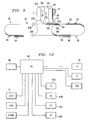
Fig. 10 is a schematic diagram of a segmented LID tilt tray Sorter control system. - Carts for use in the present invention may be substantially the same as Systems presently in use, such as those shown in
U.S. Patent No. 5,018,928, issued May 28, 1991 respectively inU.S. Patent No. 6,003,656, issued December 21, 1999 . - As shown in
Figures 3 and4 ,carts 10 haverollers 11 that allowcarts 10 to follow and move freely around thetrack 12. The undersides ofcarts 10 also have centrally mounted vertical linear induction driveelements 13. Electric linear induction motors (LIMs) 14 spaced aroundtrack 12 at regular intervals act upon linear induction driveelements 13 and propelcarts 10. Eachcart 10 is fitted with a tilt tray mechanism including atiltable tray 15. A variety of items, for example packages, bundles of mail, or parcels, are loaded onto thetrays 15 from aloading station 2 and conveyed around thetrack 12 until the item reaches a row of unloadingstations 4. The items may be off-loaded into one or more output steams that correspond to a parcel's destination by selectively tiltingtrays 15 by actuating tiltingmechanisms 16 tospecific unloading stations 4 according to a sort scheme in a manner known in the art. The Mantissa Scorpion tilt tray conveyor system, made by Mantissa Corporation of Charlotte, NC is a preferred tilt tray mechanism for use in the present invention, but other commercially available tilt tray mechanisms could be used-Referring now toFigure 5 , a LID sorter according to the invention includes twoindependent segments closed loop track 12. Because each cart has a linearinduction drive element 13,LIMs 14 may drive eachcart segment track 12. This feature eliminates the necessity of linking allcarts 10 in a closed loop.Carts 10 used to make separately movable trains orcart segments 6A. 6B are most preferably Mantissa Scorpion LID carts as described above. However, as shown inFigure 6 , the Scorpion carts are essentially T-shaped and rely on each other for support as illustrated. Eachcart 10 is joined by a suitable pivoting coupling, such as a ball and socket joint 17, tail to head with the cart behind it. Accordingly, thelast cart 10A in the segment is preferably modified to have an additional set ofrollers 11A and has a double axle rather than a single one.Rollers 11A may if necessary be provided with casters to permitcart 10A to travel around curves. The equivalent arrangement in reverse, wherein each cart frame is an inverted T-shape and thefront cart 10 has the double axle, is also within the scope of the present invention. Thus, in the present invention it is most advantageous to have onedouble axle cart 10A per segment at an end position, while the remainder of the carts are single axle carts relying at one end for support on anadjacent cart -
Multiple segments Segments carts 10 necessary for a desired process. This eliminates the expense of extra carts that are only required to complete the chain around the loop. The length of eachsegment segments several segments LIMs 14 may vary from conventional spacing based on a predetermined minimum size for segments 6. The preferred minimum distance between adjacent LIMs in themain loops LIM 14. -
Figure 7 illustrates a LID sorter according to the invention have multiple loops or sub-loops 5A, 5B connected by a pair of parallel crossover tracks 28A, 28B and switches 30A-30D at opposite ends of each segment 28A, 28B. Each switch 30 has a movable track section 31A or 31B that operates in either a transfer position or a loop position in the manner of a railroad switch. In the transfer position,switch 30A directs a segment ofcarts 6C to follow interconnecting track 28A to transfer the segment fromloop 5A toloop 5B as shown. In the loop position,switch 30B sendssegment 6B aroundloop 5A. - Tracks 28A, 28B may be provided with spaced LIM's in the same manner as
loops loops - A multi-loop system according to
Figure 7 may be operated so thatcertain cart segments loop 5A and/or 5B at all times, whereas others (such as 6C) are regularly transferred atswitches 30A-30D so that these segments circulate about the larger oval defined by both ofloops rows -
Figure 8 illustrates a simplified version of the system ofFigure 7 , wherein switches 30C, 30D are eliminated, resulting in a first small oval shapedloop 5A and a second,larger loop 5B created as an extension ofloop 5A.Segments 6A-6D are loaded with items from acommon loading station 2 onloop 5A.Segments local unloading stations 4A representing more common destinations, whereassegments remote unloading stations 4B located onloop 5B representing less common destinations. This embodiment of the invention permits foursegments 6A-6D to pass the more common unloading stations 4a, whereas only two segments pass and sort to the lesscommon unloading stations 4B. At thesingle loading station 2, computer controlled sort scheme logic may, for example, ensure that items destined for one of unloadingstations 4B are loaded onto one ofsegments -
Figure 9 shows a LID sorter according to the invention having severaladditional loops 5C to 5F which can serve as a holding area for carts with tray contents that require delayed delivery. Oneloop 5C can optionally be used as a "bone yard" or maintenance/storage area for an unused orbroken cart segment 6E. In this embodiment, switches 30B and 30D may be three position switches as shown. Segments 6 may be transferred from the sortingloops loops 5C-5F by associatedswitches 30D-30G.Loop 5C can provide an area separate from the active sorting process to perform preventative maintenance or repair work on thecarts 10, and may adjoin astorage rack 19 for carts that have been removed from the system. A loaded or unloaded cart segment that has been diverted to one ofloops 5D-5F can be reactivated when ready and moved through return switches 30I-30K along acommon return track 7 and back intoloop 5A throughswitch 30B. -
Fig. 10 shows one example of a sorter control system for operating a tilt tray sorting system of the invention as shown inFigure 7 . Apersonal computer 40 actuates a series ofsolenoids 42A-42D that control theswitches 30A-30D.Computer 40 controls theLIMs 14, which drivecarts 10, and the tiltingmechanisms 16 which tilt thetrays 15 for unloading atstations 4. Alternatively,computer 40 could control cross-belt carriers in the same manner as tiltingmechanisms 16. -
Programming computer 40 allows a user to automatically control the path and movements ofsegments 6A-6D in accordance with a predetermined sorting scheme. Eachsegment 6A-6D can be directed to sort items around theloops loops 5C-5F, in the embodiment ofFig. 9 ).Computer 40 also controls loading items onto thecart 10 atloading stations tray tilt mechanisms 16 atspecific unloading stations - For control purposes, it may prove useful to provide readable panels, such as reflective panels or light-scanable bar codes on each cart as so that unloading only occurs when the correct identification is detected at the unloading station, as for example, by scanning a bar code affixed to the cart frame. However, it may also prove possible using
computer 40 to operate the system without uniquely identifying each individual cart for unloading purposes. By tracking the location of the lead cart in a segment 6 and storing data identifying the number ofcarts 10 in that segment and the respective contents relative to a corresponding row of unloadingstations specific cart 10 with itsrespective unloading station 4. It may prove necessary in some cases to provide sensors throughout theloops 5A-5C, not merely proximate the unloadingstations computer 40 knows the exact or approximate position of eachsegment 6A-6E at all times so that switching errors and the like can be avoided. - In a typical operation using the embodiment of
Figure 5 ,computer 40 receives information from asensor 46 such as a bar code scanner concerning the destination of each of series of packages. The stream of packages is loaded from loadingstation 2 onto successive carts of asegment 6A.Computer 40 stores in memory a table of the item destination for eachsuccessive cart 10.Computer 40 also has in memory a table of thesuccessive unloading stations 4 and the destination corresponding to each. Assegment 6A passes the row of unloadingstations 4,computer 40 activates the tilt mechanism of eachcart 10 to be actuated when thatcart 10 is in registration with thematching unloading station 4. As noted above, where the number of carts is known relative to the number of unloading stations and the carts are configured with the same spacing as the row of unloading stations, then the position of the lead cart sufficiently identifies the position of all carts in the segment for unloading purposes. However, to ensure accuracy, each cart may be detected as it enters each unloading station in a manner known in the art. - As
segment 6A is unloading, theother segment 6B is loading atloading station 2, and thecomputer 40 operates LIM's 14 as needed to keepsegments loop 5.Segments segment 6B approaches unloadingstations 4. Under conditions where less than all carts in a full loop are filled with items, this embodiment avoids wasted energy associated with driving empty carts continuously around the circle. - In the embodiment of
Figure 8 ,computer 40 additionally maintains in memory a table ofcommon unloading stations 4A andrare unloading stations 4B. If acart 10 is loaded with an item that must be unloaded at arare destination 4B, thencomputer 40 operatesswitch 30A upon the approach of that cart segment 6 and sends it to pass by unloadingstations 4B. In the alternative, the system may be controlled so thatsegments loop 5B and pass bystations 4B, andsegments loop 5A. Items destined forstations 4B are diverted and set aside to be loaded only onto one ofcarts - It will be understood that the foregoing description is of preferred exemplary embodiments of the invention, and that the invention is not limited to the specific forms shown, but is limited only by the scope of the invention as expressed in the appended claims.
Claims (7)
- A sorter conveyor system, comprising a conveyor loop (5A,
5B) including a rail (12); a plurality of conveyor segments (6A, 6B), each segment comprising a series of cart units (10) each having wheel structures (11) mounted for rolling movement along the rail (12), wherein a first and last cart in each segment are adjacent to only one other cart in that segment, each cart having a tray (15) for carrying one or
more items thereon, a selectively actuable mechanism (16) which tilts the tray(15)laterally in at least one direction to unload an item from the tray (15) to any of a plurality of unloading stations (4) adjacent the conveyor loop (5A, 5B),
and a coupling mechanism for joining each cart unit (10) in each series in a head to tail relationship, and wherein one or more drive elements (13) are connected to one or more of the cart units (10) and configured to permit the conveyor segment(6A, 6B) to be driven by a linear drive,
characterized by
a plurality of linear induction drive units (14) disposed at spaced positions along the conveyor loop (5A, 5B) for driving each of the drive elements (13) of the cart units (10),
wherein the system has at least two conveyor segments (6A,
6B), and each conveyor segment (6A or 6B) can each be driven independently of each other of the plurality of conveyor segments (6A or 6B) by selective actuation of the linear induction drive units (14), further comprising a computerized control system (40) that operates the drive units (14) in a manner effective to control movement of a cart segment (6A,
6B). - A sorter conveyor system as recited in claim 1, wherein the conveyor loop (5A, 5B) has two parallel sections and two curved end sections.
- A sorter conveyor system as recited in claim 1, wherein each cart segment has a length sufficiently great so that each segment (6A, 6B) is positioned over at least one linear induction drive (14) unit at all positions on the conveyor loop (5A, 5B).
- A sorter conveyor system as recited in claim 1, wherein the conveyor loop (5A, 5B) further comprises two sub-loops (5C, 5F) and two switches (30) permitting the segments (6A or 6B) to cross between the sub-loops (5C, 5F).
- The sorter conveyor system of claim 4, wherein the sub-loops (5C, 5F)are spaced from each other, and the system further comprises first and second connecting rails permitting cart segments (6A or 6B) to travel between the spaced sub-loops (5C, 5F).
- A sorter conveyor system as recited in claim 5, wherein at least one loading station (2) and a plurality of unloading stations (4) are positioned proximate one sub-loop (5C, 5F), and a storage facility (19) is positioned proximate the other
loop. - A method for sorting and conveying using a sorter conveyor system recited in claims 1,
characterized in
operating the drive units (14) by a computerized control system (40) in a manner effective to move two or more conveyor segments (6A, 6B) on the one common rail (12), moving the conveyor segment (6A, 6B) past a loading station; loading items onto the trays (15) of one or more of the carts (10) as the carts pass the loading station (2); actuating the linear induction drive units (14) to operate only when a cart segment (6A, 6B) is passing each linear induction drive unit (14) to move the segment of carts (6A, 6B) past a row of unloading stations (4); and unloading items from the cart trays (15) to the unloading stations (4) in accordance with a sorting scheme.
Applications Claiming Priority (3)
| Application Number | Priority Date | Filing Date | Title |
|---|---|---|---|
| US255190 | 1988-10-07 | ||
| US09/255,190 US6246023B1 (en) | 1999-02-22 | 1999-02-22 | Segmented tilt tray sorter |
| PCT/US2000/004501 WO2000048739A1 (en) | 1999-02-22 | 2000-02-22 | Segmented conveyor sorter |
Publications (3)
| Publication Number | Publication Date |
|---|---|
| EP1163053A1 EP1163053A1 (en) | 2001-12-19 |
| EP1163053A4 EP1163053A4 (en) | 2004-09-08 |
| EP1163053B1 true EP1163053B1 (en) | 2010-11-17 |
Family
ID=22967237
Family Applications (1)
| Application Number | Title | Priority Date | Filing Date |
|---|---|---|---|
| EP00914665A Expired - Lifetime EP1163053B1 (en) | 1999-02-22 | 2000-02-22 | Segmented conveyor sorter |
Country Status (4)
| Country | Link |
|---|---|
| US (2) | US6246023B1 (en) |
| EP (1) | EP1163053B1 (en) |
| DE (1) | DE60045242D1 (en) |
| WO (1) | WO2000048739A1 (en) |
Families Citing this family (83)
| Publication number | Priority date | Publication date | Assignee | Title |
|---|---|---|---|---|
| US6246023B1 (en) * | 1999-02-22 | 2001-06-12 | Siemens Electrocom, L.P. | Segmented tilt tray sorter |
| US6953906B2 (en) * | 1999-08-02 | 2005-10-11 | Rapistan Systems Advertising Corp. | Delivery point sequencing mail sorting system with flat mail capability |
| AU2002221634B2 (en) | 2000-09-28 | 2007-04-26 | Dematic Corp. | Positive displacement shoe and slat sorter apparatus and method |
| US6610954B2 (en) * | 2001-02-26 | 2003-08-26 | At&C Co., Ltd. | System for sorting commercial articles and method therefor |
| US6889814B2 (en) * | 2001-05-30 | 2005-05-10 | Rapistan Systems Advertising Corp. | Article sortation system |
| US6762382B1 (en) * | 2001-10-02 | 2004-07-13 | Innovative Picking Technologies, Inc. | Track-type sortation system |
| US6917852B2 (en) * | 2002-01-24 | 2005-07-12 | Hewlett-Packard Development Company, L.P. | Automated input/output job distribution through the use of mobile input/output bins |
| US6844820B2 (en) * | 2002-01-24 | 2005-01-18 | Hewlett-Packard Development Company, Lp. | Communication link between mobile input/output bins and a data center to provide backup |
| US6744362B2 (en) | 2002-01-24 | 2004-06-01 | Hewlett-Packard Development Company, L.P. | Consumable replacement by mobile input/output bins |
| US6747229B2 (en) * | 2002-01-24 | 2004-06-08 | Hewlett-Packard Development Company, Lp. | Input/output job tagging readable by mobile input/output bins |
| US6860383B2 (en) | 2002-03-07 | 2005-03-01 | Rapistan Systems Advertising Corp. | Positive displacement sorter |
| US6921875B2 (en) * | 2002-10-08 | 2005-07-26 | Lockheed Martin Corporation | Method for sequentially ordering objects using a single pass delivery point process |
| US8776694B2 (en) | 2002-10-16 | 2014-07-15 | Cross Belt Ip, Llc | Monorail sortation system |
| US9102336B2 (en) | 2002-10-16 | 2015-08-11 | Cross Belt Ip, L.L.C. | Portable bin for sortation system |
| WO2004035365A2 (en) * | 2002-10-16 | 2004-04-29 | Transport Systems, Inc. | Monorail sortation system |
| CA2536269C (en) * | 2003-08-01 | 2012-02-28 | Dematic Corp. | Positive displacement sorter shoe |
| DE502004006514D1 (en) * | 2003-09-15 | 2008-04-24 | Siemens Ag | DEVICE FOR SORTING FLAT SHIPMENTS |
| US7414218B2 (en) * | 2004-08-16 | 2008-08-19 | Lockheed Martin Corporation | Cross circulation mail sorter stacker design with dual ported input, and method of operating the same |
| DE102004051938B4 (en) * | 2004-10-25 | 2008-02-28 | Deutsche Post Ag | Method and device for checking the loading of a transport device with objects |
| US20060187595A1 (en) * | 2005-02-22 | 2006-08-24 | International Business Machines Corporation | Apparatus and method for controlling leakage current in bipolar esd clamping devices |
| US7448499B2 (en) * | 2005-05-24 | 2008-11-11 | Lockheed Martin Corporation | Automated bundle and pallet preparation system and method of use |
| US9004272B2 (en) * | 2005-12-07 | 2015-04-14 | Ackley Machine Corporation | Method and apparatus for transporting and processing a plurality of articles |
| KR101489337B1 (en) * | 2007-01-12 | 2015-02-03 | 오펙스 코포레이션 | Item sorting method and item sorting device |
| AU2014216046B2 (en) * | 2007-01-12 | 2017-04-27 | Opex Corporation | Method and apparatus for sorting items |
| US7816617B2 (en) * | 2007-05-21 | 2010-10-19 | Lockheed Martin Corporation | Configurable intelligent conveyor system and method |
| US7684034B2 (en) * | 2007-05-24 | 2010-03-23 | Applied Vision Company, Llc | Apparatus and methods for container inspection |
| DE102007047000A1 (en) * | 2007-10-01 | 2009-04-02 | Siemens Ag | Sorting system for piece goods sorting |
| AU2010206498B2 (en) * | 2009-01-23 | 2014-04-17 | Maf Agrobotic | Fruit handling equipment |
| CA2754560C (en) | 2009-03-03 | 2019-04-09 | Ats Automation Tooling Systems Inc. | Multi-mode and multi-pitch conveyor system |
| ES2381832B1 (en) * | 2010-06-07 | 2013-04-26 | Mostoles Industrial, S.A. | TRAY CLASSIFIER |
| US20120024669A1 (en) | 2010-07-29 | 2012-02-02 | Danelski Darin L | Networked Motorized Drive Roller Conveyor |
| EP2691319B1 (en) | 2011-03-31 | 2022-05-25 | ATS Automation Tooling Systems Inc. | Pallet-based position adjustment system |
| US10229383B2 (en) | 2012-02-05 | 2019-03-12 | Matthews International Corporation | Perpetual batch order fulfillment |
| US9446908B2 (en) | 2012-02-05 | 2016-09-20 | Matthews Resources, Inc. | Conveying systems and methods of associating data with an item transported by a conveying system |
| DK2836446T3 (en) | 2012-04-09 | 2023-05-01 | Opex Corp | Method and apparatus for sorting or retrieving objects |
| US8807320B2 (en) * | 2012-06-21 | 2014-08-19 | Mantissa Corporation | Independent discharge sorting conveyor |
| EP2786946A1 (en) * | 2013-04-04 | 2014-10-08 | Knapp AG | Magnetic conveyor technology for a transport system |
| DE102013105687B4 (en) * | 2013-06-03 | 2025-08-28 | Krones Ag | Device for transporting containers with magnetic drive |
| CN105000344B (en) * | 2015-07-31 | 2018-04-17 | 深圳市欣视景科技股份有限公司 | A kind of conveyor for being used to intersect sorting system |
| EP3347780B1 (en) | 2015-09-11 | 2023-06-07 | Berkshire Grey Operating Company, Inc. | Robotic systems and methods for identifying and processing a variety of objects |
| EP3176111B1 (en) * | 2015-12-04 | 2020-02-12 | BEUMER Group GmbH & Co. KG | Item sorting device and method |
| US10730078B2 (en) | 2015-12-04 | 2020-08-04 | Berkshire Grey, Inc. | Systems and methods for dynamic sortation of objects |
| CA3007359C (en) | 2015-12-04 | 2023-03-21 | Berkshire Grey, Inc. | Systems and methods for dynamic processing of objects |
| US12350713B2 (en) | 2015-12-18 | 2025-07-08 | Berkshire Grey Operating Company, Inc. | Perception systems and methods for identifying and processing a variety of objects |
| US9937532B2 (en) | 2015-12-18 | 2018-04-10 | Berkshire Grey Inc. | Perception systems and methods for identifying and processing a variety of objects |
| CN105858196B (en) * | 2016-05-25 | 2019-04-05 | 上海丹景智能装备有限公司 | A high-precision storage location and automatic feeding system for feeding trucks |
| WO2018089486A1 (en) | 2016-11-08 | 2018-05-17 | Berkshire Grey Inc. | Systems and methods for processing objects |
| EP3544911B1 (en) | 2016-11-28 | 2023-10-18 | Berkshire Grey Operating Company, Inc. | System for providing singulation of objects for processing |
| CN110049933A (en) | 2016-12-06 | 2019-07-23 | 伯克希尔格雷股份有限公司 | For providing the system and method for the processing of the object in vehicle |
| CN114852726B (en) | 2017-03-20 | 2024-01-02 | 伯克希尔格雷营业股份有限公司 | System and method for handling objects including transport vehicles |
| CN114873119B (en) | 2017-03-20 | 2023-10-31 | 伯克希尔格雷营业股份有限公司 | Systems and methods for handling objects including moving matrix carrier systems |
| CN110446671B (en) | 2017-03-20 | 2021-09-03 | 伯克希尔格雷股份有限公司 | System and method for processing objects including a linear gantry system |
| EP3601108A1 (en) | 2017-03-20 | 2020-02-05 | Berkshire Grey, Inc. | Systems and methods for processing objects including an auto-shuttle system |
| ES2973481T3 (en) | 2017-03-23 | 2024-06-20 | Berkshire Grey Operating Company Inc | System and method for processing objects, including automated mobile matrix carriers |
| CN110662707B (en) | 2017-03-23 | 2021-12-14 | 伯克希尔格雷股份有限公司 | System and method for processing objects including automatically moving matrix boxes |
| EP3601113B1 (en) | 2017-03-24 | 2024-12-18 | Berkshire Grey Operating Company, Inc. | Systems and methods for processing objects, including automated processing |
| EP3612472A1 (en) | 2017-04-18 | 2020-02-26 | Berkshire Grey, Inc. | Systems and methods for processing objects including space efficient distribution stations and automated output processing |
| US11205059B2 (en) | 2017-04-18 | 2021-12-21 | Berkshire Grey, Inc. | Systems and methods for separating objects using conveyor transfer with one or more object processing systems |
| US11055504B2 (en) | 2017-04-18 | 2021-07-06 | Berkshire Grey, Inc. | Systems and methods for separating objects using a vacuum roller with one or more object processing systems |
| US11080496B2 (en) | 2017-04-18 | 2021-08-03 | Berkshire Grey, Inc. | Systems and methods for separating objects using vacuum diverts with one or more object processing systems |
| US11200390B2 (en) | 2017-04-18 | 2021-12-14 | Berkshire Grey, Inc. | Systems and methods for separating objects using drop conveyors with one or more object processing systems |
| US11416695B2 (en) | 2017-04-18 | 2022-08-16 | Berkshire Grey Operating Company, Inc. | Systems and methods for distributing induction of objects to a plurality of object processing systems |
| US11301654B2 (en) | 2017-04-18 | 2022-04-12 | Berkshire Grey Operating Company, Inc. | Systems and methods for limiting induction of objects to one or more object processing systems |
| WO2018200503A1 (en) | 2017-04-24 | 2018-11-01 | Berkshire Grey, Inc. | Systems and methods for providing singulation of objects for processing using object movement redistribution |
| US20200247610A1 (en) * | 2017-08-08 | 2020-08-06 | Knapp Ag | A suspension conveyor system for sorting products |
| US10608469B2 (en) * | 2017-09-28 | 2020-03-31 | Rockwell Automation Technologies, Inc. | Method and apparatus for power transfer to an independent moving cart during travel along a track |
| CN114789867B (en) | 2017-10-27 | 2024-05-24 | 伯克希尔格雷营业股份有限公司 | System and method for processing objects including a mobile matrix carrier system |
| US10668506B2 (en) * | 2018-04-24 | 2020-06-02 | Beumer Group Gmbh & Co. Kg. | Sorting conveyor with article removal device |
| US10583986B2 (en) | 2018-05-04 | 2020-03-10 | Berkshire Grey, Inc. | Systems and methods for processing objects, including automated processing stations |
| US10526146B1 (en) | 2018-09-07 | 2020-01-07 | Intelligrated Headquarters, Llc | Material handling system and article transfer |
| CA3126766C (en) | 2018-10-23 | 2023-09-19 | Berkshire Grey, Inc. | Systems and methods for dynamic processing of objects with data verification |
| CN114173944B (en) | 2019-08-08 | 2023-09-29 | 伯克希尔格雷营业股份有限公司 | Systems and methods for sorting items into bulk orders |
| US11780676B2 (en) | 2019-08-14 | 2023-10-10 | Opex Corporation | Systems and methods for managing inventory |
| US10974913B1 (en) * | 2019-11-07 | 2021-04-13 | Berne Apparel Company | Tilting tray products sorting apparatus |
| US12269681B2 (en) | 2020-03-06 | 2025-04-08 | Berkshire Grey Operating Company, Inc. | Systems and methods for providing order fulfillment using a routing conveyance system |
| US12129125B2 (en) | 2020-03-06 | 2024-10-29 | Berkshire Grey Operating Company, Inc. | Systems and methods for providing order fulfillment using a conveyor takeaway system |
| CN115210153B (en) | 2020-03-06 | 2024-01-30 | 伯克希尔格雷营业股份有限公司 | System and method for providing order fulfillment using a spiral tower system |
| EP4114766B1 (en) | 2020-03-06 | 2025-08-20 | Berkshire Grey Operating Company, Inc. | Systems and methods for providing order fulfillment using a recirculating routing system |
| WO2023064465A1 (en) | 2021-10-13 | 2023-04-20 | Berkshire Grey Operating Company, Inc. | Robotic put wall systems and methods with mobile destination location assemblies |
| EP4496760B1 (en) | 2022-03-23 | 2026-05-06 | Berkshire Grey Operating Company, Inc. | Buffering systems and methods for dynamic processing of objects |
| CN118973724A (en) | 2022-04-06 | 2024-11-15 | 伯克希尔格雷营业股份有限公司 | Object handling system and method with multi-object shuttling |
| FR3137904B1 (en) | 2022-07-12 | 2025-03-14 | Solystic | Compact high-speed sorter with two parallel lanes |
| FR3140078B1 (en) | 2022-09-26 | 2024-09-06 | Solystic | High-speed sorter with parcel receptacle trains routed onto two parallel conveyors for parcel insertion |
Family Cites Families (17)
| Publication number | Priority date | Publication date | Assignee | Title |
|---|---|---|---|---|
| US1789860A (en) * | 1926-08-04 | 1931-01-20 | Cleveland Crane Eng | Carrier system for foundries |
| US3167192A (en) * | 1961-01-10 | 1965-01-26 | Prospect Mfg Co Inc | Automatic sortation system |
| US3463298A (en) * | 1967-05-16 | 1969-08-26 | Spra Con Co The | Tray constructions for conveyors |
| US3662874A (en) | 1970-10-12 | 1972-05-16 | Butz Engineering Co | Parcel sorting conveyor system |
| FR2117759B1 (en) | 1970-12-15 | 1974-11-08 | Cytec France | |
| US3974909A (en) | 1975-08-22 | 1976-08-17 | American Chain & Cable Company, Inc. | Tilting tray sorting conveyor |
| US4004681A (en) | 1976-04-05 | 1977-01-25 | American Chain & Cable Company, Inc. | Tilting tray sorting system |
| IT1140924B (en) * | 1980-04-16 | 1986-10-10 | Francesco Canziani | SORTING AND / OR TRANSPORT SYSTEM, AND RELATED PLANTS FOR IMPLEMENTATION |
| DE3602861A1 (en) | 1986-01-31 | 1987-08-13 | Beumer Maschf Bernhard | TILTING CONVEYOR ELEMENT FOR A CONVEYOR |
| CA1316139C (en) | 1988-10-31 | 1993-04-13 | Karl Hartlepp | Sortation equipment |
| US5664660A (en) | 1989-02-24 | 1997-09-09 | Kosan Crisplant A/S | Sorter conveyor |
| US5054601A (en) * | 1989-09-19 | 1991-10-08 | Quipp, Incorporated | Sorting conveyor |
| JPH05162846A (en) * | 1991-12-12 | 1993-06-29 | Toyo Kanetsu Kk | Sorting device |
| US5489017A (en) * | 1993-11-17 | 1996-02-06 | United Parcel Service Of America, Inc. | Tilting tray package sorting apparatus |
| GB2300612B (en) | 1995-04-25 | 1998-09-30 | Crisplant As | Conveyor |
| IT1297026B1 (en) | 1997-12-29 | 1999-08-03 | Cml Handling Technology S P A | HIGH PRODUCTIVITY METHOD AND EQUIPMENT FOR PARCEL SORTING |
| US6246023B1 (en) * | 1999-02-22 | 2001-06-12 | Siemens Electrocom, L.P. | Segmented tilt tray sorter |
-
1999
- 1999-02-22 US US09/255,190 patent/US6246023B1/en not_active Expired - Fee Related
-
2000
- 2000-02-22 EP EP00914665A patent/EP1163053B1/en not_active Expired - Lifetime
- 2000-02-22 DE DE60045242T patent/DE60045242D1/en not_active Expired - Lifetime
- 2000-02-22 WO PCT/US2000/004501 patent/WO2000048739A1/en not_active Ceased
- 2000-02-22 US US09/510,090 patent/US6459061B1/en not_active Expired - Lifetime
Also Published As
| Publication number | Publication date |
|---|---|
| DE60045242D1 (en) | 2010-12-30 |
| EP1163053A4 (en) | 2004-09-08 |
| WO2000048739A1 (en) | 2000-08-24 |
| US6459061B1 (en) | 2002-10-01 |
| EP1163053A1 (en) | 2001-12-19 |
| US6246023B1 (en) | 2001-06-12 |
Similar Documents
| Publication | Publication Date | Title |
|---|---|---|
| US6459061B1 (en) | Segmented conveyor sorter | |
| KR100722572B1 (en) | Double Width Cross Belt Sorter | |
| JPH0725447A (en) | Sorting method and device | |
| US9102336B2 (en) | Portable bin for sortation system | |
| US8776694B2 (en) | Monorail sortation system | |
| US6005211A (en) | Method and apparatus for sorting articles using a matrix of conveyor cells | |
| CN1068293C (en) | Installation for sorting of individually conveyed objects | |
| JP7496707B2 (en) | Conveying device and conveying system | |
| JP6250136B2 (en) | Equipment for processing sorts | |
| US8100058B2 (en) | Monorail sortation system | |
| US20200338597A1 (en) | Automated Modular System For Sorting Items | |
| HU221473B (en) | Equipment and process for storing early bags arrived on airport | |
| EP1081065A1 (en) | Trolley with passive discharge mechanism | |
| JP3142578B2 (en) | Method and apparatus for sorting articles using a conveyor cell matrix | |
| WO1999054182A1 (en) | Freight container and method of transporting a load | |
| HUP9900844A2 (en) | Method and equipment for handling objects at high speed | |
| JP2007535456A (en) | Matrix type sorting system | |
| WO1993014008A1 (en) | Indexing, bi-directional vertical sorter with buffer conveyors | |
| US5566834A (en) | Method and system for transport of good and luggage in an airport or similar facility | |
| DK168040B1 (en) | PROCEDURE AND EQUIPMENT FOR INTERNAL TRANSPORT OF BAGGAGE IN LARGE AIRPORTS | |
| JPH09216721A (en) | Transport equipment | |
| JP2025509521A (en) | Sorting and conveyor systems | |
| CN118900815A (en) | Sorting systems and conveyor systems | |
| JPH02123019A (en) | Method and plant for sorting product in open path system |
Legal Events
| Date | Code | Title | Description |
|---|---|---|---|
| PUAI | Public reference made under article 153(3) epc to a published international application that has entered the european phase |
Free format text: ORIGINAL CODE: 0009012 |
|
| 17P | Request for examination filed |
Effective date: 20010918 |
|
| AK | Designated contracting states |
Kind code of ref document: A1 Designated state(s): AT BE CH CY DE DK ES FI FR GB GR IE IT LI LU MC NL PT SE |
|
| RAP1 | Party data changed (applicant data changed or rights of an application transferred) |
Owner name: SIEMENS AKTIENGESELLSCHAFT |
|
| RBV | Designated contracting states (corrected) |
Designated state(s): DE FR GB IT |
|
| A4 | Supplementary search report drawn up and despatched |
Effective date: 20040728 |
|
| RIC1 | Information provided on ipc code assigned before grant |
Ipc: 7B 65G 47/96 A Ipc: 7B 07C 3/08 B Ipc: 7B 61B 13/08 B |
|
| 17Q | First examination report despatched |
Effective date: 20050531 |
|
| GRAP | Despatch of communication of intention to grant a patent |
Free format text: ORIGINAL CODE: EPIDOSNIGR1 |
|
| GRAS | Grant fee paid |
Free format text: ORIGINAL CODE: EPIDOSNIGR3 |
|
| GRAA | (expected) grant |
Free format text: ORIGINAL CODE: 0009210 |
|
| AK | Designated contracting states |
Kind code of ref document: B1 Designated state(s): DE FR GB IT |
|
| REG | Reference to a national code |
Ref country code: GB Ref legal event code: FG4D |
|
| REF | Corresponds to: |
Ref document number: 60045242 Country of ref document: DE Date of ref document: 20101230 Kind code of ref document: P |
|
| PLBI | Opposition filed |
Free format text: ORIGINAL CODE: 0009260 |
|
| PLAX | Notice of opposition and request to file observation + time limit sent |
Free format text: ORIGINAL CODE: EPIDOSNOBS2 |
|
| 26 | Opposition filed |
Opponent name: CRISPLANT A/S Effective date: 20110816 |
|
| REG | Reference to a national code |
Ref country code: DE Ref legal event code: R026 Ref document number: 60045242 Country of ref document: DE Effective date: 20110816 |
|
| PLAF | Information modified related to communication of a notice of opposition and request to file observations + time limit |
Free format text: ORIGINAL CODE: EPIDOSCOBS2 |
|
| PLBB | Reply of patent proprietor to notice(s) of opposition received |
Free format text: ORIGINAL CODE: EPIDOSNOBS3 |
|
| PGFP | Annual fee paid to national office [announced via postgrant information from national office to epo] |
Ref country code: FR Payment date: 20120227 Year of fee payment: 13 |
|
| PGFP | Annual fee paid to national office [announced via postgrant information from national office to epo] |
Ref country code: GB Payment date: 20120208 Year of fee payment: 13 Ref country code: IT Payment date: 20120222 Year of fee payment: 13 |
|
| PLAB | Opposition data, opponent's data or that of the opponent's representative modified |
Free format text: ORIGINAL CODE: 0009299OPPO |
|
| PGFP | Annual fee paid to national office [announced via postgrant information from national office to epo] |
Ref country code: DE Payment date: 20120420 Year of fee payment: 13 |
|
| R26 | Opposition filed (corrected) |
Opponent name: CRISPLANT A/S Effective date: 20110816 |
|
| RAP2 | Party data changed (patent owner data changed or rights of a patent transferred) |
Owner name: SIEMENS AKTIENGESELLSCHAFT |
|
| GBPC | Gb: european patent ceased through non-payment of renewal fee |
Effective date: 20130222 |
|
| REG | Reference to a national code |
Ref country code: FR Ref legal event code: ST Effective date: 20131031 |
|
| REG | Reference to a national code |
Ref country code: DE Ref legal event code: R119 Ref document number: 60045242 Country of ref document: DE Effective date: 20130903 |
|
| PG25 | Lapsed in a contracting state [announced via postgrant information from national office to epo] |
Ref country code: IT Free format text: LAPSE BECAUSE OF NON-PAYMENT OF DUE FEES Effective date: 20130222 |
|
| PG25 | Lapsed in a contracting state [announced via postgrant information from national office to epo] |
Ref country code: GB Free format text: LAPSE BECAUSE OF NON-PAYMENT OF DUE FEES Effective date: 20130222 Ref country code: FR Free format text: LAPSE BECAUSE OF NON-PAYMENT OF DUE FEES Effective date: 20130228 Ref country code: DE Free format text: LAPSE BECAUSE OF NON-PAYMENT OF DUE FEES Effective date: 20130903 |
|
| RAP2 | Party data changed (patent owner data changed or rights of a patent transferred) |
Owner name: SIEMENS AKTIENGESELLSCHAFT |
|
| PLBD | Termination of opposition procedure: decision despatched |
Free format text: ORIGINAL CODE: EPIDOSNOPC1 |
|
| PLBM | Termination of opposition procedure: date of legal effect published |
Free format text: ORIGINAL CODE: 0009276 |
|
| STAA | Information on the status of an ep patent application or granted ep patent |
Free format text: STATUS: OPPOSITION PROCEDURE CLOSED |
|
| 27C | Opposition proceedings terminated |
Effective date: 20140828 |