EP1162706A2 - Q-switched frequency converted laser - Google Patents
Q-switched frequency converted laser Download PDFInfo
- Publication number
- EP1162706A2 EP1162706A2 EP01113761A EP01113761A EP1162706A2 EP 1162706 A2 EP1162706 A2 EP 1162706A2 EP 01113761 A EP01113761 A EP 01113761A EP 01113761 A EP01113761 A EP 01113761A EP 1162706 A2 EP1162706 A2 EP 1162706A2
- Authority
- EP
- European Patent Office
- Prior art keywords
- laser
- laser pulse
- harmonic
- pause period
- mirror
- Prior art date
- Legal status (The legal status is an assumption and is not a legal conclusion. Google has not performed a legal analysis and makes no representation as to the accuracy of the status listed.)
- Granted
Links
Images





Classifications
-
- H—ELECTRICITY
- H01—ELECTRIC ELEMENTS
- H01S—DEVICES USING THE PROCESS OF LIGHT AMPLIFICATION BY STIMULATED EMISSION OF RADIATION [LASER] TO AMPLIFY OR GENERATE LIGHT; DEVICES USING STIMULATED EMISSION OF ELECTROMAGNETIC RADIATION IN WAVE RANGES OTHER THAN OPTICAL
- H01S3/00—Lasers, i.e. devices using stimulated emission of electromagnetic radiation in the infrared, visible or ultraviolet wave range
- H01S3/10—Controlling the intensity, frequency, phase, polarisation or direction of the emitted radiation, e.g. switching, gating, modulating or demodulating
-
- B—PERFORMING OPERATIONS; TRANSPORTING
- B23—MACHINE TOOLS; METAL-WORKING NOT OTHERWISE PROVIDED FOR
- B23K—SOLDERING OR UNSOLDERING; WELDING; CLADDING OR PLATING BY SOLDERING OR WELDING; CUTTING BY APPLYING HEAT LOCALLY, e.g. FLAME CUTTING; WORKING BY LASER BEAM
- B23K26/00—Working by laser beam, e.g. welding, cutting or boring
- B23K26/02—Positioning or observing the workpiece, e.g. with respect to the point of impact; Aligning, aiming or focusing the laser beam
- B23K26/06—Shaping the laser beam, e.g. by masks or multi-focusing
- B23K26/064—Shaping the laser beam, e.g. by masks or multi-focusing by means of optical elements, e.g. lenses, mirrors or prisms
- B23K26/0643—Shaping the laser beam, e.g. by masks or multi-focusing by means of optical elements, e.g. lenses, mirrors or prisms comprising mirrors
-
- B—PERFORMING OPERATIONS; TRANSPORTING
- B23—MACHINE TOOLS; METAL-WORKING NOT OTHERWISE PROVIDED FOR
- B23K—SOLDERING OR UNSOLDERING; WELDING; CLADDING OR PLATING BY SOLDERING OR WELDING; CUTTING BY APPLYING HEAT LOCALLY, e.g. FLAME CUTTING; WORKING BY LASER BEAM
- B23K26/00—Working by laser beam, e.g. welding, cutting or boring
- B23K26/02—Positioning or observing the workpiece, e.g. with respect to the point of impact; Aligning, aiming or focusing the laser beam
- B23K26/06—Shaping the laser beam, e.g. by masks or multi-focusing
- B23K26/064—Shaping the laser beam, e.g. by masks or multi-focusing by means of optical elements, e.g. lenses, mirrors or prisms
-
- H—ELECTRICITY
- H01—ELECTRIC ELEMENTS
- H01S—DEVICES USING THE PROCESS OF LIGHT AMPLIFICATION BY STIMULATED EMISSION OF RADIATION [LASER] TO AMPLIFY OR GENERATE LIGHT; DEVICES USING STIMULATED EMISSION OF ELECTROMAGNETIC RADIATION IN WAVE RANGES OTHER THAN OPTICAL
- H01S3/00—Lasers, i.e. devices using stimulated emission of electromagnetic radiation in the infrared, visible or ultraviolet wave range
- H01S3/005—Optical devices external to the laser cavity, specially adapted for lasers, e.g. for homogenisation of the beam or for manipulating laser pulses, e.g. pulse shaping
-
- H—ELECTRICITY
- H01—ELECTRIC ELEMENTS
- H01S—DEVICES USING THE PROCESS OF LIGHT AMPLIFICATION BY STIMULATED EMISSION OF RADIATION [LASER] TO AMPLIFY OR GENERATE LIGHT; DEVICES USING STIMULATED EMISSION OF ELECTROMAGNETIC RADIATION IN WAVE RANGES OTHER THAN OPTICAL
- H01S3/00—Lasers, i.e. devices using stimulated emission of electromagnetic radiation in the infrared, visible or ultraviolet wave range
- H01S3/09—Processes or apparatus for excitation, e.g. pumping
- H01S3/091—Processes or apparatus for excitation, e.g. pumping using optical pumping
- H01S3/0912—Electronics or drivers for the pump source, i.e. details of drivers or circuitry specific for laser pumping
-
- H—ELECTRICITY
- H01—ELECTRIC ELEMENTS
- H01S—DEVICES USING THE PROCESS OF LIGHT AMPLIFICATION BY STIMULATED EMISSION OF RADIATION [LASER] TO AMPLIFY OR GENERATE LIGHT; DEVICES USING STIMULATED EMISSION OF ELECTROMAGNETIC RADIATION IN WAVE RANGES OTHER THAN OPTICAL
- H01S3/00—Lasers, i.e. devices using stimulated emission of electromagnetic radiation in the infrared, visible or ultraviolet wave range
- H01S3/10—Controlling the intensity, frequency, phase, polarisation or direction of the emitted radiation, e.g. switching, gating, modulating or demodulating
- H01S3/10038—Amplitude control
-
- H—ELECTRICITY
- H01—ELECTRIC ELEMENTS
- H01S—DEVICES USING THE PROCESS OF LIGHT AMPLIFICATION BY STIMULATED EMISSION OF RADIATION [LASER] TO AMPLIFY OR GENERATE LIGHT; DEVICES USING STIMULATED EMISSION OF ELECTROMAGNETIC RADIATION IN WAVE RANGES OTHER THAN OPTICAL
- H01S3/00—Lasers, i.e. devices using stimulated emission of electromagnetic radiation in the infrared, visible or ultraviolet wave range
- H01S3/10—Controlling the intensity, frequency, phase, polarisation or direction of the emitted radiation, e.g. switching, gating, modulating or demodulating
- H01S3/102—Controlling the intensity, frequency, phase, polarisation or direction of the emitted radiation, e.g. switching, gating, modulating or demodulating by controlling the active medium, e.g. by controlling the processes or apparatus for excitation
- H01S3/1022—Controlling the intensity, frequency, phase, polarisation or direction of the emitted radiation, e.g. switching, gating, modulating or demodulating by controlling the active medium, e.g. by controlling the processes or apparatus for excitation by controlling the optical pumping
-
- H—ELECTRICITY
- H01—ELECTRIC ELEMENTS
- H01S—DEVICES USING THE PROCESS OF LIGHT AMPLIFICATION BY STIMULATED EMISSION OF RADIATION [LASER] TO AMPLIFY OR GENERATE LIGHT; DEVICES USING STIMULATED EMISSION OF ELECTROMAGNETIC RADIATION IN WAVE RANGES OTHER THAN OPTICAL
- H01S3/00—Lasers, i.e. devices using stimulated emission of electromagnetic radiation in the infrared, visible or ultraviolet wave range
- H01S3/10—Controlling the intensity, frequency, phase, polarisation or direction of the emitted radiation, e.g. switching, gating, modulating or demodulating
- H01S3/11—Mode locking; Q-switching; Other giant-pulse techniques, e.g. cavity dumping
- H01S3/1123—Q-switching
- H01S3/117—Q-switching using intracavity acousto-optic devices
-
- H—ELECTRICITY
- H01—ELECTRIC ELEMENTS
- H01S—DEVICES USING THE PROCESS OF LIGHT AMPLIFICATION BY STIMULATED EMISSION OF RADIATION [LASER] TO AMPLIFY OR GENERATE LIGHT; DEVICES USING STIMULATED EMISSION OF ELECTROMAGNETIC RADIATION IN WAVE RANGES OTHER THAN OPTICAL
- H01S3/00—Lasers, i.e. devices using stimulated emission of electromagnetic radiation in the infrared, visible or ultraviolet wave range
- H01S3/10—Controlling the intensity, frequency, phase, polarisation or direction of the emitted radiation, e.g. switching, gating, modulating or demodulating
- H01S3/13—Stabilisation of laser output parameters, e.g. frequency or amplitude
- H01S3/1306—Stabilisation of the amplitude
Definitions
- the present invention relates to a laser device with a Q switch for generating a higher harmonics, a method of controlling the device, and a laser processing machine comprising the device.
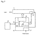
- FIG. 7 shows a configuration of a conventional a harmonic-generating Q switch laser device.
- the device comprises a laser head 11, a Q switch 12, an excitation light source 13, a radio frequency (RF) driver 14 for the Q switch, a controller 15, an interface 16, a power source 17, and an operation unit 18.
- RF radio frequency
- An oscillation condition instruction set through the operation unit 18 such as a personal computer (PC) is sent to the control circuit 15 through the interface 16.
- the controller 15 interprets the transmitted oscillation condition instruction, generates a control signal according to the instruction, transmits the condition to the excitation light source 13 and RF driver 14 for the Q switch, and determines the oscillation condition of the laser head.
- the controller 15 also controls the alarm from the laser head 11 and a temperature of a nonlinear optical crystal.
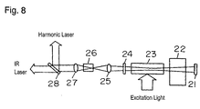
- Fig. 8 shows an internal structure of the laser head 11 of the harmonic-generating Q switch laser device shown in Fig. 7.
- the head 11 comprises a reflecting mirror 21, a Q switch element 22, a gain medium 23, an output mirror 24, a condenser lens 25, a nonlinear optical crystal 26, an optical lens 27, a narrow band filter or dichroic mirror 28, and two lenses 25 and 27.
- the lenses 25, 27 function as a collimator.
- the device where the nonlinear optical crystal 26 is disposed outside of the mirrors 21, 24 is called an extra cavity system.
- this harmonic-generating Q switch laser head When an excitation light enters the gain medium 23, an optical resonation occurs between the reflector mirror 21 and output mirror 24.
- the Q switch element 22 inserted between the mirrors 21 and 24 When the Q switch element 22 inserted between the mirrors 21 and 24 is turned on, the optical path opens, and the laser oscillates. When the element is turned off, the optical path closes, and the oscillation stops. Thus, a pulse laser oscillation is enabled.
- the Q switch element 22 is turned on and off by the RF driver 14 for the Q switch, and enables the Q switch laser head to pulse-oscillate.
- the laser light issued from the output mirror 24 is condensed by the condenser lens 25, and emitted to the nonlinear optical crystal 26.
- a harmonic laser is generated by the nonlinear optical crystal 26, is collimated by the optical lens 27, and is separated into an IR laser, a fundamental wave and harmonic laser by the narrow band filter or dichroic mirror 28.
- the harmonic laser is used for a processing machine
- the power P SHG of a harmonic laser of second harmonic generation is expressed in the following formula.
- P SHG d eff ⁇ I eff ⁇ (P IR ) 2 /A
- d eff is a nonlinear constant, a constant determined by the type of the nonlinear optical crystal 26, the larger constant, a higher conversion efficiency
- l eff is an effective length, a length in which the nonlinear optical crystal 26 has a nonlinear effect
- P IR is the power of the fundamental wave
- A is a laser beam area.
- the nonlinear optical crystal 26 has a limited light strength, i.e., the crystal is broken when a light exceeding a damage threshold is input. Even if the light is not reaching the damage threshold, a light approaching the damage threshold affects a life of the nonlinear optical crystal 26.
- Fig. 9 shows the oscillation characteristic of the Q switch laser.
- an arc current of a lamp or current of a laser diode (LD) is maintained in constant, and accordingly, the excitation light power is kept constant, and the Q switch is turned on and off.
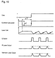
- the excitation light enters the gain medium 23 for a long period while the Q switch closes before an oscillation is started, a gain accumulated in the gain medium 23 excesses a specified value. Therefore, when a gate signal for starting an oscillation is turned on, a giant pulse is generated at a first shot or several shots depending on cases. This giant pulse may destroy the nonlinear optical crystal 26 or shorten the life of the crystal.
- the controller of the Q switch laser device may have a first pulse suppression (FPS) function.
- FPS pulse suppression
- the FPS function of the Q switch laser device will be explained.
- the excitation light into the gain medium 23 is weakened to such an extent as to maintain a specified gain while the Q switch is closed for a long time.
- the laser gain accumulated in the gain medium 23 is prevented from getting excessive. Since the maximum excitation light power is limited, the gradient of building-up the laser gain is limited. The period until the specified laser gain is accumulated depends on the interval of the pulse train following the first pulse, that is, a pulse frequency. Therefore, whenever the pulse frequency changes, the condition of the FPS function such as the laser gain retention current ⁇ I and retention period ⁇ T must be adjusted.
- the rise time of the Q switch may be delayed, but it is similarly needed to set the condition of the FPS function for each pulse frequency.
- Fig. 11 shows an optical system of a laser processing machine having the harmonic-generating Q switch laser device.
- the processing machine comprises a harmonic-generating Q switch laser device 31, a collimator lens 32, a mask changer 33, a bend mirror 34, a galvanoscanner 35, a scanner lens 36, and a working table 37.
- the laser emitted from the harmonic-generating Q switch laser device 31 have the beam diameter optimized by the collimator 32, and is emitted to the mask on the mask changer 33. A portion of the emitted laser passes through the mask, and is condensed at a specified position through the scanner lens 36 by the galvanoscanner 35 through the bend mirror 34, and processes the work fixed on the table 37.
- While processing the work generally, a pulse train of a specified frequency is needed, a long pause period is necessary in order to convey the work, and the pulse oscillation and pause period are repeated.
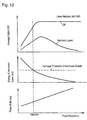
- Fig. 12 shows an output characteristic of the harmonic-generating Q switch laser device.
- a low pulse frequency increases the pulse energy, and increases a possibility of damaging the nonlinear optical crystal 26 or shortening of the life of the crystal.
- the harmonic-generating Q switch laser device 31 generally incorporated in the laser processing machine has the FPS function as mentioned above.
- the pulse frequency is required to change on the way.
- the FPS function is suspended, or even if the FPS function is employed for safety, the period for sending the condition setting instruction of the FPS function is required, and makes an entire processing time longer.
- the galvanoscanner 35 installed in the processing machine. may eliminates an affect of the pulse to the work. That, however, does not protect the nonlinear optical crystal 26, and the reliability of the device is still not improved.
- a laser device and a method of controlling the device are provided for protecting a nonlinear optical crystal without a loss of a cycle time, and for assuring a reliability of a laser processing machine. And a laser processing machine having the device and a processing method using the machine are provided.
- the laser device generates a laser pulse train formed of a sequence of laser pulses.
- the laser device comprises an output mirror, a reflector mirror, a gain medium disposed between the output mirror and reflector mirror for accumulating the laser gain, a Q switch disposed between the output mirror and the reflector mirror for turning on and off a laser oscillation by the output mirror, reflector mirror and gain medium, a nonlinear optical crystal for generating a harmonic laser by recieving a fundamental wave laser by the laser oscillation.
- the laser oscillation is turned on by the Q switch, and during a second pause period before each laser pulse, the laser oscillation is turned off by the Q switch.
- Fig. 1 is a diagram for explaining an operation of a Q switch laser device according to a first exemplary embodiment of the present invention.
- Fig. 2 is a diagram for explaining an operation of other Q switch laser device according to the first embodiment.
- Fig. 3 is a diagram for explaining an operation of a Q switch laser device according to a second exemplary embodiment of the present invention.
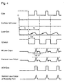
- Fig. 4 is a diagram for explaining an the operation of other Q switch laser device according to the second embodiment.
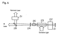
- Fig. 5 shows a configuration of a laser head of a harmonic-generating Q switch laser device according to the embodiment.
- Fig. 6 shows an output characteristic of harmonic generating Q switch laser device according to the embodiment.
- Fig. 7 shows a configuration of the harmonic-generating Q switch laser device.
- Fig. 8 shows a configuration of a laser head of the harmonic-generating Q switch laser device.
- Fig. 9 shows a control of a conventional harmonic-generating Q switch laser oscillator.
- Fig. 10 shows a control of a conventional harmonic-generating Q switch laser oscillator.
- Fig. 11 shows a laser processing machine using a harmonic-generating Q switch laser device.
- Fig. 12 shows an output characteristic of a conventional harmonic-generating Q switch laser device.
- a laser device according to a first exemplary embodiment of the present invention will be explained with referring to Fig. 1.
- the harmonic-generating Q switch laser device according to the first embodiment is same as shown in Fig. 8, and a control of the device will be explained.
- an arc current of a lamp emitting excitation light or a current of a laser diode (LD) is maintained in constant, and the excitation light power is kept constant, and the Q switch is turned on and off to control a laser oscillation.
- the Q switch which is turned on sets the device to a continuous oscillation mode for oscillating the laser continuously.
- the Q switch which is turned off makes a laser power be accumulated in the laser medium irradiated with an excitation light.
- the second pause period T2A is equal to the duration of a pulse period T0 of the laser pulse train extracted by a pulse width TW.
- the pulse width TW is so small to be negligible for the pulse period T0, and hence the pause period T2A substantially coincides nearly with the pulse period T0.
- a specified second pause period T2A nearly coinciding with the pulse period T0 of the pulse train which is preset before a generation of the pulse makes the laser gain before the oscillation of the harmonic pulse be always kept at a specified value.
- Fig. 6 shows a laser output characteristic of the laser device according to the embodiment.
- the pulse energy at a low frequency where the second pause period T2A is long is prevented from rising excessively, and the nonlinear optical crystal is protected owing to the characteristic.
- This control therefore, makes a harmonic pulse be oscillated stably, and eliminates a damage or a shortening of life of the nonlinear optical crystal. Further, the control prevents a giant pulse from being generated without the FPS function.
- a stable harmonic pulse is obtained even if the pulse train is generated randomly.
- the stable pulse improves the quality of the laser processing and generates no loss time even when the pulse oscillation condition changes, so that a laser processing machine of high productivity may be provided.
- a constant arc current of a lamp emitting excitation light or a current of an LD laser effectively prevents the life of the lamp or the LD from being shortened due to a heat cycle and fluctuations.
- a harmonic-generating Q switch laser device of an intra cavity system is shown in Fig. 5.
- the nonlinear optical crystal 26 is positioned differently from the device shown in Fig. 8, and is located between the mirrors 21 and 24, and hence it is called the intra cavity system.
- This device includes a harmonic dispensing device 51 like an optical modulator such as an acousto-optical modulator (AOM).
- AOM acousto-optical modulator
- Other components are the same as in the extra cavity system shown in Fig. 8 although the order is different.
- a weak harmonic laser may be issued with an output infrared ray (IR) during the first pause period T1 of the laser pulse, i.e., a continuous wave (CW) of a fundamental wave laser.
- IR infrared ray
- CW continuous wave
- This device installed in the laser processing machine may generate the weak harmonic laser exceeding a processing threshold.
- the harmonic pulse is dispensed for extracting only harmonic pulse as shown in Fig. 2 by the harmonic dispensing device 51 to which a dispensing signal is input.
- the device 51 is disposed in the harmonic output path as shown in Fig. 5.
- the laser device of the intra cavity system has the same effect as the extra cavity system.
- the gain medium 23 of this device receives an excitation light having a constant power as the same as in the first embodiment.
- the Q switch 22 which is turned on sets the device to a continuous oscillation mode.
- the Q switch 22 which is turned off makes more gain accumulate in the gain medium 23 by the excitation light.
- the pause period T2B is shorter than the pulse period T0 of pulse train. During the pause period T2B, the gain accumulated in the medium 23 is controlled, and the pulse output is thus controlled.
- the Q switch 22 which is turned on during the first pause period T1 before the oscillation of the harmonic laser sets the device to the continuous oscillation mode, and prevents the laser gain for excessively accumulating in the gain medium.
- the pause period T2B which is shorter than the pulse period, controls the laser gain before the oscillation of the harmonic pulse stably.
- Fig. 6 shows a laser output characteristic according to the embodiments.
- the pulse energy at low frequency where the second pause period T2B is long, is prevented from rising excessively, and the nonlinear optical crystal is protected from damage or shortening of life owing to this characteristic.
- the shorter the pause period TB2 the much smaller the pulse energy, and the nonlinear optical crystal is protected more securely. Therefore, the harmonic pulse always oscillates stably, and the laser output is controlled by the pause period T2B.
- the giant pulse is not generated.
- the laser processing machine having such laser device not only a stable harmonic pulse is obtained even if the pulse train is generated randomly, but also the laser output can be controlled precisely through the pause period control, so that a laser processing quality may be excellent. Further, a loss time does not occur even when the pulse oscillation condition changes, so that a high productivity may be presented.
- a constant arc current of the lamp emitting an excitation light or a current of an LD effectively prevents the life of the lamp or LD from being shortened due to fluctuations.
- a harmonic-generating Q switch laser device of intra cavity system according to the second embodiment is shown in Fig. 5.
- the nonlinear optical crystal 26 is positioned differently from the device shown in Fig. 8, and is located between the mirrors 21 and 24.
- the control signal is shown in Fig. 4.
- a harmonic dispensing device 51 is an optical modulator such as acousto-optical modulator (AOM).
- AOM acousto-optical modulator
- a weak harmonic laser may be issued with an infrared ray (IR) during the first pause period T1 of the laser pulse, that is, a continuous wave (CW) of a fundamental wave laser.
- IR infrared ray
- CW continuous wave
- the harmonic pulse is dispensed by the harmonic dispensing device 51.
- the device 51 a control signal for dispensing only harmonic pulse as shown in Fig. 4 is input, and is disposed in the harmonic output path as shown in Fig. 5.
- a weak harmonic laser may be generated also in a period T3 when the Q switch is turned on. But it is shielded by the harmonic dispensing device 51 and does not come out. As a result, the laser device of the intra cavity system has the same effect as the extra cavity system.
Landscapes
- Physics & Mathematics (AREA)
- Optics & Photonics (AREA)
- Engineering & Computer Science (AREA)
- Plasma & Fusion (AREA)
- Mechanical Engineering (AREA)
- Electromagnetism (AREA)
- Lasers (AREA)
- Optical Modulation, Optical Deflection, Nonlinear Optics, Optical Demodulation, Optical Logic Elements (AREA)
- Laser Beam Processing (AREA)
Abstract
Description
Claims (36)
- A laser device for generating a laser pulse train formed of a sequence of laser pulses, comprising:wherein the laser oscillation is turned on by said Q switch during a first pause period before a generation of the laser pulse train, and the laser oscillation is turned off by said Q switch during a second pause period before a generation of the laser pulse.an output mirror;a reflector mirror;a gain medium disposed between said output mirror and reflector mirror for accumulating a laser gain;a Q switch disposed between said output mirror and reflector mirror for turning on and off a laser oscillation by said output mirror, reflector mirror, and gain medium; anda nonlinear optical crystal irradiated with a fundamental wave laser by the laser oscillation for generating a harmonic laser,
- The laser device of claim 1, wherein said nonlinear optical crystal is disposed between said output mirror and reflector mirror.
- The laser device of claim 1, further comprising a harmonic dispensing device disposed in an output path of the laser pulse.
- The laser device of claim 3, wherein said harmonic dispensing device is an optical modulator.
- The laser device of claim 1, wherein said nonlinear optical crystal is disposed at an opposite side of said reflector mirror about said output mirror.
- The laser device of claim 1, wherein the second pause period is substantially equal to a period of the laser pulse train extracted by a width of the laser pulse.
- The laser device of claim 1, wherein the second pause period is smaller than the period of the laser pulse train extracted by the width of the laser pulse.
- The laser device of claim 7, wherein a power of the laser pulse is controlled by the second pause period.
- The laser device of claim 1, further comprising a filter for separating the harmonic laser generated by said nonlinear optical crystal and the fundamental wave laser.
- A method of controlling a laser device having: an output mirror; a reflector mirror; and a gain medium disposed between said output mirror and reflector mirror for accumulating laser gain, for generating a laser pulse train formed of a sequence of periodic laser pulses by a laser oscillation by said output mirror, reflector mirror and gain medium, said method comprising the steps of:turning on the laser oscillation during a first pause period before a generation of the laser pulse train; andturning off the laser oscillation during a second pause period before a generation of the laser pulse.
- The method of claim 10, further comprising the step of dispensing only the laser pulse.
- The method of claim 11, wherein said step of dispensing only the laser pulse comprises the sub step of dispensing only the laser pulse by an optical modulator.
- The method of claim 10, wherein the second pause period is substantially equal to a period of the laser pulse train extracted by a width of the laser pulse.
- The method of claim 10, wherein the second pause period is smaller than the period of the laser pulse train extracted by the width of the laser pulse.
- The method of claim 14, wherein a power of the laser pulse is controlled with the second pause period.
- The method of claim 10, further comprising the step of generating harmonic laser from a fundamental wave laser by the laser oscillation.
- The method of claim 16, further comprising the step of separating the harmonic laser and the fundamental wave laser.
- A laser processing machine for processing a work, having a laser device for generating a laser pulse train formed of a sequence of laser pulses, said laser device comprising:wherein the laser oscillation is turned on by said Q switch during a first pause period before a generation of the laser pulse train, and the laser oscillation is turned off by said Q switch during a second pause period before a generation of the laser pulse.an output mirror;a reflector mirror;a gain medium disposed between said output mirror and reflector mirror for accumulating a laser gain;a Q switch disposed between said output mirror and reflector mirror for turning on and off the laser oscillation by said output mirror, reflector mirror and gain medium; anda nonlinear optical crystal irradiated with a fundamental wave laser by the laser oscillation for generating a harmonic laser,
- The laser processing machine of claim 18, wherein said nonlinear optical crystal is disposed between said output mirror and reflector mirror.
- The laser processing machine of claim 18, further comprising a harmonic dispensing device disposed in an output path of the laser pulse.
- The laser processing machine of claim 20, wherein said harmonic dispensing device is an optical modulator.
- The laser processing machine of claim 18, wherein said nonlinear optical crystal is disposed at an opposite side of said reflector mirror about said output mirror.
- The laser processing machine of claim 18, wherein the second pause period is substantially equal to a period of the laser pulse train extracted by a width of the laser pulse.
- The laser processing machine of claim 18, wherein the second pause period is smaller than the period of the laser pulse train extracted by the width of the laser pulse.
- The laser processing machine of claim 24, wherein a power of the laser pulse is controlled with the second pause period.
- The laser processing machine of claim 18, further comprising a filter for separating the harmonic laser generated by the nonlinear optical crystal and the fundamental wave laser.
- The laser processing machine of claim 18, wherein the work is a printed circuit board.
- A method of processing a work using a laser processing machine including a laser device having: an output mirror; a reflector mirror; and a gain medium disposed between said output mirror and reflector mirror for accumulating a laser gain, for generating a laser pulse train formed of a sequence of periodic laser pulses by a laser oscillation by said output mirror, reflector mirror and gain medium, said method comprising the steps of:turning on the laser oscillation during a first pause period before a generation of the laser pulse train; andturning off the laser oscillation during a second pause period before a generation of the laser pulse.
- The method of claim 28, further comprising the step of dispensing only the laser pulse.
- The method of claim 29, wherein said step of dispensing only the laser pulse comprises the sub step of dispensing only the laser pulse by an optical modulator.
- The method of claim 28, wherein the second pause period is substantially equal to a period of the laser pulse train extracted by a width of the laser pulse.
- The method of claim 28, wherein the second pause period is smaller than the period of the laser pulse train extracted by the width of the laser pulse.
- The method of claim 32, wherein a power of the laser pulse is controlled with the second pause period.
- The method of claim 28, further comprising the step of generating a harmonic laser from a fundamental wave laser by the laser oscillation.
- The method of claim 34, further comprising the step of separating the harmonic laser and the fundamental wave laser.
- The method of claim 28, wherein the work is a printed circuit board.
Applications Claiming Priority (2)
| Application Number | Priority Date | Filing Date | Title |
|---|---|---|---|
| JP2000168538A JP2001352120A (en) | 2000-06-06 | 2000-06-06 | Laser apparatus, control method therefor, laser processing method and laser processing machine using the same |
| JP2000168538 | 2000-06-06 |
Publications (3)
| Publication Number | Publication Date |
|---|---|
| EP1162706A2 true EP1162706A2 (en) | 2001-12-12 |
| EP1162706A3 EP1162706A3 (en) | 2004-09-22 |
| EP1162706B1 EP1162706B1 (en) | 2012-01-25 |
Family
ID=18671528
Family Applications (1)
| Application Number | Title | Priority Date | Filing Date |
|---|---|---|---|
| EP01113761A Expired - Lifetime EP1162706B1 (en) | 2000-06-06 | 2001-06-05 | Q-switched frequency converted laser |
Country Status (6)
| Country | Link |
|---|---|
| US (1) | US6782012B2 (en) |
| EP (1) | EP1162706B1 (en) |
| JP (1) | JP2001352120A (en) |
| KR (1) | KR100776100B1 (en) |
| NO (1) | NO324734B1 (en) |
| TW (1) | TW505552B (en) |
Cited By (1)
| Publication number | Priority date | Publication date | Assignee | Title |
|---|---|---|---|---|
| WO2004095657A1 (en) * | 2003-04-14 | 2004-11-04 | Coherent, Inc. | Q-switching method for pulse train generation by interrupting cw operation of the laser for adjustable time periods |
Families Citing this family (14)
| Publication number | Priority date | Publication date | Assignee | Title |
|---|---|---|---|---|
| JP3838064B2 (en) * | 2001-09-28 | 2006-10-25 | 松下電器産業株式会社 | Laser control method |
| DE10319327A1 (en) * | 2003-04-29 | 2004-11-25 | Siemens Ag | Device for radiation image recording with laser unit for linear marking of a person under examination, with laser being pulse-operated with a pulse-pause ratio of 1:n |
| JP4492041B2 (en) * | 2003-06-04 | 2010-06-30 | パナソニック株式会社 | Laser processing apparatus and laser processing method |
| US20060289411A1 (en) * | 2005-06-24 | 2006-12-28 | New Wave Research | Laser system with multiple operating modes and work station using same |
| JP4725237B2 (en) * | 2005-08-16 | 2011-07-13 | 株式会社Ihi | Laser resonator |
| JP4869738B2 (en) * | 2006-03-02 | 2012-02-08 | 株式会社フジクラ | Fiber laser output stabilization method and fiber laser |
| JP2007273558A (en) * | 2006-03-30 | 2007-10-18 | Mitsubishi Electric Corp | Wavelength conversion laser device |
| KR20090018165A (en) * | 2006-05-31 | 2009-02-19 | 사이버 레이저 가부시끼가이샤 | Laser pulse generator and method and laser processing device and method |
| JP2010199315A (en) * | 2009-02-25 | 2010-09-09 | Toshiba Corp | Solid-state laser oscillator and method for modulating solid-state laser output pulse |
| JP5842496B2 (en) * | 2011-09-20 | 2016-01-13 | 株式会社島津製作所 | Solid state pulse laser equipment |
| US8767291B2 (en) * | 2012-03-16 | 2014-07-01 | Kla-Tencor Corporation | Suppression of parasitic optical feedback in pulse laser systems |
| JP6008689B2 (en) * | 2012-10-24 | 2016-10-19 | シチズンホールディングス株式会社 | Laser light source device and laser projector using laser light source device |
| JP6388823B2 (en) * | 2014-12-01 | 2018-09-12 | 株式会社ディスコ | Laser processing equipment |
| CN108471043A (en) * | 2018-04-27 | 2018-08-31 | 国科世纪激光技术(天津)有限公司 | Acousto-optic Q modulation solid state laser and control method |
Family Cites Families (12)
| Publication number | Priority date | Publication date | Assignee | Title |
|---|---|---|---|---|
| US3747019A (en) | 1970-07-16 | 1973-07-17 | Union Carbide Corp | Method and means for stabilizing the amplitude and repetition frequency of a repetitively q-switched laser |
| JPS5879788A (en) * | 1981-11-06 | 1983-05-13 | Nec Corp | Driving method for q-switching laser device |
| US4930901A (en) * | 1988-12-23 | 1990-06-05 | Electro Scientific Industries, Inc. | Method of and apparatus for modulating a laser beam |
| JPH02260479A (en) | 1989-03-30 | 1990-10-23 | Toshiba Corp | Laser oscillator |
| JP2677711B2 (en) | 1990-12-26 | 1997-11-17 | ファイン・マシニング株式会社 | YAG laser processing machine for thin film precision processing |
| US5226051A (en) * | 1991-06-04 | 1993-07-06 | Lightwave Electronics | Laser pump control for output power stabilization |
| JP3199836B2 (en) | 1992-05-18 | 2001-08-20 | 株式会社東芝 | Wavelength conversion laser device |
| US5812569A (en) * | 1997-03-21 | 1998-09-22 | Lumonics, Inc. | Stabilization of the output energy of a pulsed solid state laser |
| DE19747180A1 (en) * | 1997-10-24 | 1999-07-22 | Coherent Luebeck Gmbh | Pulse laser with first pulse control |
| US6009110A (en) * | 1998-03-11 | 1999-12-28 | Lightwave Electronics Corporation | Pulse amplitude control in frequency-converted lasers |
| US6339604B1 (en) * | 1998-06-12 | 2002-01-15 | General Scanning, Inc. | Pulse control in laser systems |
| US6108356A (en) * | 1999-03-05 | 2000-08-22 | Photonics Industries International, Inc. | Intracavity optical parametric oscillators |
-
2000
- 2000-06-06 JP JP2000168538A patent/JP2001352120A/en active Pending
-
2001
- 2001-06-05 KR KR1020010031306A patent/KR100776100B1/en not_active Expired - Fee Related
- 2001-06-05 EP EP01113761A patent/EP1162706B1/en not_active Expired - Lifetime
- 2001-06-05 NO NO20012758A patent/NO324734B1/en not_active IP Right Cessation
- 2001-06-05 US US09/873,416 patent/US6782012B2/en not_active Expired - Lifetime
- 2001-06-05 TW TW090113576A patent/TW505552B/en not_active IP Right Cessation
Cited By (2)
| Publication number | Priority date | Publication date | Assignee | Title |
|---|---|---|---|---|
| WO2004095657A1 (en) * | 2003-04-14 | 2004-11-04 | Coherent, Inc. | Q-switching method for pulse train generation by interrupting cw operation of the laser for adjustable time periods |
| US6931035B2 (en) | 2003-04-14 | 2005-08-16 | Coherent, Inc. | Q-switching method for pulse train generation |
Also Published As
| Publication number | Publication date |
|---|---|
| NO324734B1 (en) | 2007-12-03 |
| US6782012B2 (en) | 2004-08-24 |
| TW505552B (en) | 2002-10-11 |
| NO20012758L (en) | 2001-12-07 |
| EP1162706B1 (en) | 2012-01-25 |
| US20020018495A1 (en) | 2002-02-14 |
| NO20012758D0 (en) | 2001-06-05 |
| EP1162706A3 (en) | 2004-09-22 |
| KR100776100B1 (en) | 2007-11-15 |
| JP2001352120A (en) | 2001-12-21 |
| KR20010110320A (en) | 2001-12-13 |
Similar Documents
| Publication | Publication Date | Title |
|---|---|---|
| EP1162706B1 (en) | Q-switched frequency converted laser | |
| US7599407B2 (en) | Laser control method, laser apparatus, laser treatment method used for the same, laser treatment apparatus | |
| US7769059B2 (en) | High power Q-switched laser for soft tissue ablation | |
| CN1850417B (en) | Laser welding method and laser welding apparatus | |
| JP2009130143A (en) | LASER OSCILLATION DEVICE AND ITS CONTROL METHOD | |
| JP2001189513A (en) | Q-switched solid-state laser with adjustable pulse width | |
| JP2002208750A (en) | Laser oscillator and laser pulse control method thereof | |
| JP6508058B2 (en) | Light source device and wavelength conversion method | |
| JP2015153917A (en) | Laser processing device | |
| US5241551A (en) | High average power laser which generates radiation at a wavelength near 530 nm | |
| KR102033657B1 (en) | Wavelength converter | |
| JP7319664B2 (en) | LASER PROCESSING APPARATUS AND LASER PROCESSING METHOD | |
| JPH11307859A (en) | Solid-state laser device | |
| JP3700516B2 (en) | Wavelength conversion laser device and laser processing device | |
| JP5834981B2 (en) | Solid state laser equipment | |
| JP4137227B2 (en) | Laser oscillator | |
| JP4270228B2 (en) | LASER DEVICE, ITS CONTROL METHOD, LASER PROCESSING METHOD USING THE SAME, AND LASER MACHINE | |
| JP2003017787A (en) | Drive circuit for solid state laser device and Q switch driver | |
| JP2008010720A (en) | Fiber laser equipment | |
| JP2002246675A (en) | Laser oscillation device and control method thereof | |
| JP2002151777A (en) | Laser oscillator and its laser pulse control method | |
| JPH11354876A (en) | Ultrasonic q-switch device and q-switched laser output device | |
| JP2021118270A (en) | Laser oscillator | |
| JPH10275950A (en) | Laser device and laser processing device | |
| JPS5940591A (en) | Method of transmitting laser pulse by means of optical fiber |
Legal Events
| Date | Code | Title | Description |
|---|---|---|---|
| PUAI | Public reference made under article 153(3) epc to a published international application that has entered the european phase |
Free format text: ORIGINAL CODE: 0009012 |
|
| AK | Designated contracting states |
Kind code of ref document: A2 Designated state(s): AT BE CH CY DE DK ES FI FR GB GR IE IT LI LU MC NL PT SE TR |
|
| AX | Request for extension of the european patent |
Free format text: AL;LT;LV;MK;RO;SI |
|
| PUAL | Search report despatched |
Free format text: ORIGINAL CODE: 0009013 |
|
| AK | Designated contracting states |
Kind code of ref document: A3 Designated state(s): AT BE CH CY DE DK ES FI FR GB GR IE IT LI LU MC NL PT SE TR |
|
| AX | Request for extension of the european patent |
Extension state: AL LT LV MK RO SI |
|
| RIC1 | Information provided on ipc code assigned before grant |
Ipc: 7H 01S 3/11 A Ipc: 7H 01S 3/108 B Ipc: 7G 02F 1/37 B Ipc: 7H 05K 3/00 B Ipc: 7B 23K 26/00 B |
|
| 17P | Request for examination filed |
Effective date: 20040906 |
|
| AKX | Designation fees paid |
Designated state(s): DE FI FR GB SE |
|
| 17Q | First examination report despatched |
Effective date: 20080207 |
|
| RAP1 | Party data changed (applicant data changed or rights of an application transferred) |
Owner name: PANASONIC CORPORATION |
|
| GRAP | Despatch of communication of intention to grant a patent |
Free format text: ORIGINAL CODE: EPIDOSNIGR1 |
|
| GRAS | Grant fee paid |
Free format text: ORIGINAL CODE: EPIDOSNIGR3 |
|
| GRAA | (expected) grant |
Free format text: ORIGINAL CODE: 0009210 |
|
| AK | Designated contracting states |
Kind code of ref document: B1 Designated state(s): DE FI FR GB SE |
|
| REG | Reference to a national code |
Ref country code: GB Ref legal event code: FG4D |
|
| REG | Reference to a national code |
Ref country code: DE Ref legal event code: R096 Ref document number: 60146019 Country of ref document: DE Effective date: 20120322 |
|
| REG | Reference to a national code |
Ref country code: SE Ref legal event code: TRGR |
|
| PLBE | No opposition filed within time limit |
Free format text: ORIGINAL CODE: 0009261 |
|
| STAA | Information on the status of an ep patent application or granted ep patent |
Free format text: STATUS: NO OPPOSITION FILED WITHIN TIME LIMIT |
|
| 26N | No opposition filed |
Effective date: 20121026 |
|
| REG | Reference to a national code |
Ref country code: DE Ref legal event code: R097 Ref document number: 60146019 Country of ref document: DE Effective date: 20121026 |
|
| REG | Reference to a national code |
Ref country code: DE Ref legal event code: R084 Ref document number: 60146019 Country of ref document: DE |
|
| REG | Reference to a national code |
Ref country code: GB Ref legal event code: 746 Effective date: 20140703 |
|
| REG | Reference to a national code |
Ref country code: DE Ref legal event code: R084 Ref document number: 60146019 Country of ref document: DE Effective date: 20140620 |
|
| REG | Reference to a national code |
Ref country code: FR Ref legal event code: PLFP Year of fee payment: 16 |
|
| REG | Reference to a national code |
Ref country code: FR Ref legal event code: PLFP Year of fee payment: 17 |
|
| PGFP | Annual fee paid to national office [announced via postgrant information from national office to epo] |
Ref country code: GB Payment date: 20170620 Year of fee payment: 17 Ref country code: DE Payment date: 20170621 Year of fee payment: 17 Ref country code: FR Payment date: 20170621 Year of fee payment: 17 |
|
| PGFP | Annual fee paid to national office [announced via postgrant information from national office to epo] |
Ref country code: SE Payment date: 20170613 Year of fee payment: 17 Ref country code: FI Payment date: 20170609 Year of fee payment: 17 |
|
| REG | Reference to a national code |
Ref country code: DE Ref legal event code: R119 Ref document number: 60146019 Country of ref document: DE |
|
| REG | Reference to a national code |
Ref country code: SE Ref legal event code: EUG |
|
| PG25 | Lapsed in a contracting state [announced via postgrant information from national office to epo] |
Ref country code: FI Free format text: LAPSE BECAUSE OF NON-PAYMENT OF DUE FEES Effective date: 20180605 Ref country code: SE Free format text: LAPSE BECAUSE OF NON-PAYMENT OF DUE FEES Effective date: 20180606 |
|
| GBPC | Gb: european patent ceased through non-payment of renewal fee |
Effective date: 20180605 |
|
| PG25 | Lapsed in a contracting state [announced via postgrant information from national office to epo] |
Ref country code: GB Free format text: LAPSE BECAUSE OF NON-PAYMENT OF DUE FEES Effective date: 20180605 Ref country code: FR Free format text: LAPSE BECAUSE OF NON-PAYMENT OF DUE FEES Effective date: 20180630 Ref country code: DE Free format text: LAPSE BECAUSE OF NON-PAYMENT OF DUE FEES Effective date: 20190101 |