EP1162610A2 - Focus error correction from tilt measurement - Google Patents
Focus error correction from tilt measurement Download PDFInfo
- Publication number
- EP1162610A2 EP1162610A2 EP01401363A EP01401363A EP1162610A2 EP 1162610 A2 EP1162610 A2 EP 1162610A2 EP 01401363 A EP01401363 A EP 01401363A EP 01401363 A EP01401363 A EP 01401363A EP 1162610 A2 EP1162610 A2 EP 1162610A2
- Authority
- EP
- European Patent Office
- Prior art keywords
- speed
- perpendicular direction
- calculating
- disk
- planar shape
- Prior art date
- Legal status (The legal status is an assumption and is not a legal conclusion. Google has not performed a legal analysis and makes no representation as to the accuracy of the status listed.)
- Withdrawn
Links
Images




Classifications
-
- G—PHYSICS
- G01—MEASURING; TESTING
- G01B—MEASURING LENGTH, THICKNESS OR SIMILAR LINEAR DIMENSIONS; MEASURING ANGLES; MEASURING AREAS; MEASURING IRREGULARITIES OF SURFACES OR CONTOURS
- G01B11/00—Measuring arrangements characterised by the use of optical techniques
- G01B11/30—Measuring arrangements characterised by the use of optical techniques for measuring roughness or irregularity of surfaces
- G01B11/306—Measuring arrangements characterised by the use of optical techniques for measuring roughness or irregularity of surfaces for measuring evenness
-
- G—PHYSICS
- G11—INFORMATION STORAGE
- G11B—INFORMATION STORAGE BASED ON RELATIVE MOVEMENT BETWEEN RECORD CARRIER AND TRANSDUCER
- G11B7/00—Recording or reproducing by optical means, e.g. recording using a thermal beam of optical radiation by modifying optical properties or the physical structure, reproducing using an optical beam at lower power by sensing optical properties; Record carriers therefor
- G11B7/08—Disposition or mounting of heads or light sources relatively to record carriers
- G11B7/09—Disposition or mounting of heads or light sources relatively to record carriers with provision for moving the light beam or focus plane for the purpose of maintaining alignment of the light beam relative to the record carrier during transducing operation, e.g. to compensate for surface irregularities of the latter or for track following
- G11B7/095—Disposition or mounting of heads or light sources relatively to record carriers with provision for moving the light beam or focus plane for the purpose of maintaining alignment of the light beam relative to the record carrier during transducing operation, e.g. to compensate for surface irregularities of the latter or for track following specially adapted for discs, e.g. for compensation of eccentricity or wobble
- G11B7/0956—Disposition or mounting of heads or light sources relatively to record carriers with provision for moving the light beam or focus plane for the purpose of maintaining alignment of the light beam relative to the record carrier during transducing operation, e.g. to compensate for surface irregularities of the latter or for track following specially adapted for discs, e.g. for compensation of eccentricity or wobble to compensate for tilt, skew, warp or inclination of the disc, i.e. maintain the optical axis at right angles to the disc
-
- G—PHYSICS
- G11—INFORMATION STORAGE
- G11B—INFORMATION STORAGE BASED ON RELATIVE MOVEMENT BETWEEN RECORD CARRIER AND TRANSDUCER
- G11B7/00—Recording or reproducing by optical means, e.g. recording using a thermal beam of optical radiation by modifying optical properties or the physical structure, reproducing using an optical beam at lower power by sensing optical properties; Record carriers therefor
- G11B7/08—Disposition or mounting of heads or light sources relatively to record carriers
- G11B7/09—Disposition or mounting of heads or light sources relatively to record carriers with provision for moving the light beam or focus plane for the purpose of maintaining alignment of the light beam relative to the record carrier during transducing operation, e.g. to compensate for surface irregularities of the latter or for track following
- G11B7/0901—Disposition or mounting of heads or light sources relatively to record carriers with provision for moving the light beam or focus plane for the purpose of maintaining alignment of the light beam relative to the record carrier during transducing operation, e.g. to compensate for surface irregularities of the latter or for track following for track following only
-
- G—PHYSICS
- G11—INFORMATION STORAGE
- G11B—INFORMATION STORAGE BASED ON RELATIVE MOVEMENT BETWEEN RECORD CARRIER AND TRANSDUCER
- G11B7/00—Recording or reproducing by optical means, e.g. recording using a thermal beam of optical radiation by modifying optical properties or the physical structure, reproducing using an optical beam at lower power by sensing optical properties; Record carriers therefor
- G11B7/08—Disposition or mounting of heads or light sources relatively to record carriers
- G11B7/09—Disposition or mounting of heads or light sources relatively to record carriers with provision for moving the light beam or focus plane for the purpose of maintaining alignment of the light beam relative to the record carrier during transducing operation, e.g. to compensate for surface irregularities of the latter or for track following
- G11B7/0908—Disposition or mounting of heads or light sources relatively to record carriers with provision for moving the light beam or focus plane for the purpose of maintaining alignment of the light beam relative to the record carrier during transducing operation, e.g. to compensate for surface irregularities of the latter or for track following for focusing only
Definitions
- the present invention relates to a planar shape characteristic measuring apparatus and a planar shape characteristic measuring method which measure, for example, characteristic values relating to the shape of a measured surface of a disk such as an optical disk.
- a disk-shaped recording medium that is, an optical disk 101, comprises an optical disk substrate 103 made of an optically transparent plastic provided on one surface with a data recording surface 104 and provided with a data recording area 102 within a predetermined area in the data recording surface 104.
- an optical disk where the data recording area 102 in the data recording surface 104 is provided with, for example, as shown in Fig. 8A, a continuous groove 105 and a land 106 adjacent thereto provided spirally for every track by a predetermined track pitch P (1 to 2 ⁇ m) on the data recording surface 104 of one side of the disk substrate 103 and an optical disk where, as shown in Fig. 8B, the data recording surface 104 is provided with a series of pits 108 spirally for every track by a predetermined track pitch.
- a phase changing film or a magnetic film, a light reflecting layer, and a protective film layer are formed in that order on the data recording surface 104 on which the grooves 105 shown in Fig. 8A is provided.
- One of the grooves 105 and the lands 106 on the data recording surface 104 is used as a recording area, while the other is used as a light reflecting area for tracking.
- a light reflecting layer and a protective film layer are formed in that order on the data recording surface 104 on which the series of the pits 108 shown in Fig. 8B is provided.
- the series of the pits 108 on the data recording surface 104 is used as both a recording area and a diffraction grating for tracking.
- a laser beam condensed by an object lens (not shown) mounted on an optical pickup is fired from the non-data surface 107 at the side opposite to the data recording surface 104 of the optical disk substrate 103 while rotating the optical disk.
- a data recordable optical disk information is optically recorded in a recording layer on the land 106 by the beam or the information optically recorded on the recording layer is read by the reflected light beam. Further, for example the light beam reflected from the groove 105 is detected for tracking so that the laser beam for recording or reproduction is always focused on a predetermined track.
- a write-once type (read-only) optical disk information is read and tracking performed by detecting the reflected and diffracted beam from the surface 104 provided with the series of pits 108 due to the beam from the non-data surface 107 to the optical pickup.
- an optical disk formed with a light reflecting surface 104 comprising a light reflecting layer and a transparent layer 111 having a constant thickness about 0.1 mm in that order.
- an optical pickup (not shown) is arranged at the side of the transparent layer 111 formed on the surface 104 of the optical disk substrate 103 and fires a laser beam while the optical disk is being rotated.
- the optical disk substrate 103 is generally formed by injection molding of plastic.
- warping occurs along with heat distortion at the time of molding and changes in the environment such as the air temperature or humidity. Further, undulation occurs at the surface of the disk due to warping of the molds at the time of molding.
- up-down vibration occurs at the surface of the optical disk substrate 103 leading to the focal position of a data reading lens deviating from the data recording surface of the disk (defocus state) or the data recording surface becoming tilted from a focal surface of the data reading lens (skew state).
- a spot condensed by the optical pickup ends up being influenced by the aberration.
- the magnitude of the aberration depends on the numerical aperture (NA) of a pickup lens.
- NA numerical aperture
- the aberration caused by the defocus is proportional to the second power of the numerical aperture (NA), while the aberration caused by the skew is proportional to the third power of the numerical aperture (NA). That is, due to the larger numerical aperture (NA), the allowable defocus and skew become smaller.
- the high density optical disk such as shown in FIG. 8 is structured with a thin transparent layer 111 of a thickness of about 0.1 mm placed on the data recording surface 104 on which the grooves and the lands or the series of pits of the disk substrate 103 are formed.
- An object of the present invention is to provide a planar shape characteristic measuring apparatus and a planar shape characteristic measuring method which can precisely and efficiently measure characteristics relating to the shape of a measured surface of a disk such as a data recording surface of an optical disk.
- a planar shape characteristic measuring apparatus comprising a speed detecting means for detecting a perpendicular direction speed of a measured surface of a rotating disk and a tilt angle calculating means for calculating a tilt angle in the rotational direction of said measured surface to a reference surface at each measuring position based on the linear speed at each measuring position detected by said speed detecting means and the detected perpendicular direction speed.
- the planar shape characteristic measuring apparatus further comprises a digital filtering means for removing a noise component contained in speed data detected by said speed detecting means and a filter coefficient calculating means for calculating a filter coefficient in accordance with a sampling rate of said speed detecting means so that a filter characteristic of said digital filtering means becomes a predetermined filter coefficient.
- said tilt angle calculating means uses a value of said perpendicular direction speed divided by said linear speed as a tangent of said tilt angle and calculates said tilt angle by an inverse function of the tangent.
- the planar shape characteristic measuring apparatus further comprises a rotating means for rotating said disk; a moving means for relatively moving said speed detecting means in the radial direction of said disk; an input means for inputting a radius of said disk at a measuring position detected by said speed detecting means and a target linear speed at said measuring position; and a control means for calculating a speed for rotating said disk based on the input radius and target linear speed, rotating said disk at the calculated speed, and outputting a control command for moving said speed detecting means to the measuring position of said input radius to said rotating means and moving means.
- said speed detecting means detects said perpendicular direction speed by a non-contact means at a measured surface of said disk.
- said speed detecting means comprises a laser Doppler speed meter.
- said disk comprises a recording medium enabling at least one of optically recording and reproduction of information; and said measured surface comprises a data recording surface of said recording medium.
- the planar shape characteristic measuring apparatus further comprises a displacement calculating means for calculating a perpendicular direction displacement of said measured surface based on the detected perpendicular direction speed; an acceleration calculating means for calculating a perpendicular direction acceleration of a measured surface of said disk at each detecting position based on the detected perpendicular direction speed; and a tracking error calculating means for calculating an amount of tracking error which does not able tracking of unevenness of said measured surface predicted to occur in a servo system for making a predetermined object track a target position in a perpendicular direction from a measured surface of said rotating disk based on the detected perpendicular direction speed and a gain characteristic of said servo system.
- said object is an optical pickup for performing at least one of recording of information onto a data recording surface of said recording medium and reproduction of information from said data recording surface or a lens mounted on said optical pickup; and said servo system comprises a focus servo system for making the focus of the optical pickup or the lens mounted on said optical pickup track a target position in a direction perpendicular to said data recording surface.
- said tracking error calculating means comprises a band-pass filter for removing high and low frequency noise components contained in detected perpendicular direction speed data and an integrator for integrating by time series the output from said band-pass filter.
- a planar shape characteristic measuring method comprising a speed detecting step for detecting a perpendicular direction speed of a measured surface of a rotating disk and a tilt angle calculating step for calculating a tilt angle in the rotational direction of said measured surface with respect to a reference surface at each measuring position based on a linear speed of said measured surface at each measuring position and the detected perpendicular direction speed.
- the method further comprises a filtering step for removing a noise component contained in speed data detected in said speed detecting step by a digital filter and a filter coefficient calculating step for calculating a filter coefficient in accordance with a sampling rate of said speed detecting step so that a filter characteristic of said digital filter becomes a predetermined filter characteristic.
- said tilt angle calculating step uses a value of said perpendicular direction speed divided by said linear speed as a tangent of said tilt angle and calculates said tilt angle by an inverse function of the tangent.
- said speed detecting step comprises a step for inputting a radius of said disk at a measuring position and a target linear speed at said measuring position, a step for calculating a speed for rotating said disk based on the input radius and target linear speed and for rotating said disk at the calculated speed, and a step for moving a predetermined speed detecting means which detects said perpendicular direction speed to the measuring position of the input radius.
- said speed detecting step detects said perpendicular direction speed by a noncontact means at a measured surface of said disk.
- said speed detecting step detects said perpendicular direction speed by a laser Doppler speed meter.
- a recording medium which enables at least one of optical recording and reproduction of information is used for said disk; and said measured surface comprises a data recording surface of said recording medium.
- the method further comprises a displacement calculating step for calculating a perpendicular direction displacement of said measured surface based on the detected perpendicular direction speed; an acceleration calculating step for calculating a perpendicular direction acceleration of a measured surface of said disk at each detecting position based on the detected perpendicular direction speed; and a tracking error calculating step for calculating an amount of tracking error which does not able tracking of unevenness of said measured surface predicted to occur in a servo system for making a predetermined object track a target position in a perpendicular direction from a measured surface of said rotating disk based on the detected perpendicular direction speed and a gain characteristic of said servo system.
- said object is an optical pickup for performing at least one of recording of information onto a data recording surface of said recording medium and reproduction of information from said data recording surface or a lens mounted on said optical pickup; and said servo system comprises a focus servo system for making the focus of the optical pickup or the lens mounted on said optical pickup track a target position in a direction perpendicular to said data recording surface.
- said tracking error calculating step removes high and low frequency noise components contained in the detected perpendicular direction speed data by a band-pass filter and calculates said amount of tracking error by integrating by time series the output from this band-pass filter.
- the perpendicular direction speed of a rotating disk is detected and the tilt angle in the rotational direction at the measuring position, the so-called tangential skew, is calculated from the detected perpendicular direction speed and the linear speed at a measuring position.
- the linear speed at a measuring position can be specified from a radius of the measuring position and a speed of the disk. Because the perpendicular direction speed of the disk is a value detected directly by a laser Doppler speed meter for example, the precision of calculation of the tangential skew can be increased.
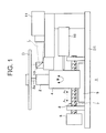
- Figure 1 is a view of the configuration of a planar shape characteristic measuring apparatus according to an embodiment of the present invention.
- a planar shape characteristic measuring apparatus 1 comprises a spindle motor 2 which holds and rotates an optical disk D as a disk-shaped recording medium, a goniometer 4 for adjusting a tilt of the rotating shaft of the spindle motor 2, a slide motor 6, a sliding mechanism 8, a laser Doppler speed meter 11, and a potentiometer 10.
- the spindle motor 2 corresponds to one embodiment of the rotating means of the present invention
- the slide motor 6 and the sliding mechanism 8 constitute the moving means of the present invention.
- the optical disk D is provided, for example, with a 0.1 mm light transparent layer on a data recording surface.
- the data recording surface of the optical disk D comprises a light reflecting surface formed by, for example, a metal film by vapor deposition and reflecting light.
- the optical disk D is not limited to a disk having a 0.1 mm transparent layer on a light reflecting surface. Other various kinds of optical disks may be used.
- the slide mechanism 8 movably holds the goniometer 4 in the radial direction of the optical disk D .
- the slide motor 6 rotates a screw shaft 7 which is rotatably held on a base BS in the slide mechanism 8.
- This screw shaft 7 is screwed into the goniometer 4.
- the goniometer 4 is movably guided by a slide base member 9 which is provided on a base BS and moves in the direction of arrows A1 and A2 by the rotation of the screw shaft 7.
- the potentiometer 10 is fixed on the base BS. This potentiometer 10 detects the position of the spindle motor 2 in the slide direction of the slide mechanism 8 shown by the arrows A1 and A2, that is, the position of the optical disk D .
- the laser Doppler speed meter 11 fires a laser beam L toward a prism 13.
- the prism 13 makes the laser beam L which is output from the laser Doppler speed meter 11 strike the data recording surface of the optical disk D.
- the laser Doppler speed meter 11 and the prism 13 are adjusted in height so that the light beam is focused on the data recording surface of the optical disk D .
- the laser Doppler speed meter 11 detects the speed of the optical disk D in the direction perpendicular to the data recording surface of the optical disk D by comparing the output laser beam with the reflected light beam.
- the laser beam L output from the laser Doppler speed meter 11 may be focused at any radial position of the optical disk D by changing the position of the slide mechanism 8.
- Figure 2 is a view of the configuration of a control system of a planar shape characteristic measuring apparatus according to an embodiment of the present invention.
- the planar shape characteristic measuring apparatus 1 further comprises a control/processing apparatus 51, a spindle driver 71 for driving the spindle motor 2, and a spindle driver 72 for driving the slide motor 6.
- the control/processing apparatus 51 comprises a personal computer for example and is provided with a man-machine interface such as a keyboard, a mouse, and a display.
- the control/processing apparatus 51 comprises, for example, an analog-to-digital converter 73 which converts a detected signal 10s detected by the potentiometer 10 to a digital signal of a predetermined form and an analog-to-digital converter 74 which converts a detected signal detected by the laser Doppler speed meter 11 to a digital signal of a predetermined form.
- the analog-to-digital converter 74 samples the detected signal of the laser Doppler speed meter 11 at a sampling rate determined by a signal Sc output from the control/processing apparatus 51.
- the spindle driver 71 provides the spindle motor 2 with a drive current in accordance with the output control signal 51sa output from the control/processing apparatus 51.
- the slide driver 72 provides the slide motor 6 with a drive current in accordance with the output control signal 51sb from the control/processing apparatus 51.
- Figure 3 is a view for describing the configuration of the control/processing apparatus 51.
- the control/processing apparatus 51 comprises a speed data input unit 52, a data input unit 53, a control unit 54, a sampling rate calculating unit 55, a filter coefficient calculating unit 56, a digital filtering unit 57, a tracking error calculating unit 58, a tilt angle calculating unit 61, a displacement calculating unit 60, an acceleration calculating unit 59, and a display unit 62.
- the data input unit 53, the control unit 54, the filter coefficient calculating unit 56, the digital filtering unit 57, the tracking error calculating unit 58, the tilt angle calculating unit 61, the displacement calculating unit 60, and the acceleration calculating unit 59 correspond to one embodiment of the input means, the control means, the filter coefficient calculating means, the filtering means, the tracking error calculating means, the tilt angle calculating means, the displacement calculating means, and the acceleration calculating unit 59 correspond to one embodiment of the input means, the control means, the filter coefficient calculating means, the filtering means, the tracking error calculating means, the tilt angle calculating means, the displacement calculating means, and the acceleration calculating means of the present invention, respectively.
- the speed data input unit 52 receives as input and holds perpendicular direction speed data V of the data recording surface of the optical disk D detected by the laser Doppler speed meter 11.
- the data input unit 53 receives as input and holds radius data R at a measuring position of the optical disk D detected by the laser Doppler speed meter 11 and a target linear speed Lv at the measuring position.
- the data input unit 53 receives as input and holds the number Sn of data samplings per rotation of the optical disk D having a speed V detected by the laser Doppler speed meter 11.
- the data input unit 53 receives as input a filter characteristic of the digital filtering unit 57 and a filter characteristic Fr of the tracking error calculating unit 58.
- this filter characteristic Fr is a gain characteristic of the digital filtering unit 57 and the tracking error calculating unit 58.
- the control unit 54 calculates a speed N of the optical disk D based on the radius data R and the target linear speed Lv at a measuring position input to the data input unit 53 and outputs a control command 51sa for rotating the optical disk D at the calculated speed N to the spindle driver 71.
- control unit 54 outputs to the slide driver 72 a control command 51sb for moving the measuring position of the optical disk D measured by the laser Doppler speed meter 11 to the measuring position of the radius data R input to the data input unit 53.
- control unit 54 controls the radial position of the spindle motor 2 based on the position of the spindle motor 2 fed back from the potentiometer 10.
- the sampling rate calculating unit 55 calculates a sampling rate Sr from the radius data R of a measuring position, the target linear speed Lv, and the number Sn of data samplings input to the data input unit 53.
- the filter coefficient calculating unit 56 calculates a filter coefficient of a digital filter which constitutes the digital filtering unit 57 and the tracking error calculating unit 58 based on the sampling rate Sr which is calculated in the sampling rate calculating unit 55 and the filter characteristic which is input to the data input unit 53.
- the digital filtering unit 57 comprised a low-pass filter for removing for example noise due to dust or scratches on the surface of the optical disk D and noise of high frequency in a data transmission system etc. contained in the speed data V detected by the laser Doppler speed meter 11 used in the tilt angle calculating unit 61, the displacement calculating unit 60, and the acceleration calculating unit 59.
- This low-pass filter is realizable by an IIR digital filter for example.
- the filter coefficient which determines the filter characteristic of this low-pass filter is calculated in the filter coefficient calculating unit 56.
- the tilt angle calculating unit 61 calculates a tilt angle in the rotational direction of the data recording surface of the optical disk D at each measuring position with respect to a reference surface based on the linear speed (scan speed) Vs at each measuring position in the optical disk D by the laser Doppler speed meter 11 and the perpendicular direction speed V detected by the laser Doppler speed meter 11.
- the displacement calculating unit 60 calculates the perpendicular direction displacement of the data recording surface of the rotating optical disk D by integrating the perpendicular direction speed V detected by the laser Doppler speed meter 11.
- the acceleration calculating unit 59 calculates the perpendicular direction acceleration of the data recording surface of the rotating optical disk D by differentiating the perpendicular direction speed V detected by the laser Doppler speed meter 11.
- the tracking error calculating unit 58 calculates an amount of tracking error which does not enable tracking of unevenness of the data recording surface of the optical disk D predicted to occur in a servo system for making a predetermined object track a target position in a perpendicular direction from a measured surface of said rotating disk based on the perpendicular direction speed detected by the laser Doppler speed meter 11 and a gain characteristic of said servo system.
- the tracking error calculating unit 58 calculates the amount of tracking error of a focus servo system for making the focus of an optical pickup which carries out at least one of recording of information on the data recording surface and reproduction of information from the data recording surface of the optical disk D or a lens mounted on the optical pickup track a target position in a direction perpendicular to the data recording surface.
- the tracking error calculating unit 58 comprises a band-pass filter of a filter characteristic input to the data input unit 53 and an integrator for integrating the output from this band-pass filter.
- These band-pass filter and integrator can be constructed by an IIR digital filter for example.
- This band-pass filter is provided with a transfer function characteristic of the above focus servo system and further has a characteristic of removing low frequency noise in surface vibration of the disk D and high frequency noise in a transmission system etc.
- the display unit 62 displays the results obtained in the tilt angle calculating unit 61, displacement calculating unit 60, acceleration calculating unit 59, and tracking error calculating unit 58 on a display screen of a display apparatus after processing to predetermined forms.
- step S1 the filter characteristics of the tracking error calculating unit 58 and the digital filtering unit 57 are input (step S1).
- step S2 the radius R of the optical disk D at a measuring position and the linear speed (scan speed) Lv at this radius R are input (step S2). Note that the number Sn of data samplings is input at this step.
- step S3 When measuring starts (step S3), the control unit 54 moves the slide mechanism 8 so that the measuring position of the laser Doppler speed meter 11 reaches the position of the input radius R (step S4).
- control unit 54 calculates the speed N of the spindle motor 2 from the input radius R and linear speed Lv and then drives the motor (step S5).
- the sampling rate calculating unit 55 calculates the sampling rate Sr based on the input radius R , the linear speed Lv, and the number Sn of data samplings (step S6).
- filter coefficients of the tracking error calculating unit 58 and the digital filtering unit 57 are calculated based on the calculated sampling rate Sr and the input filter characteristic (step S7). Due to this, even if the sampling rate Sr changes, a constant filter characteristic is always obtained.
- the control/processing apparatus 1 fetches the detected signal of the laser Doppler speed meter 11 from the analog-to-digital converter 74 at the calculated sampling rate Sr (step S8).
- step S9 when speed data of one rotation of the optical disk D is fetched, digital filter processing is carried out for this data in the digital filtering unit 57 (step S9).
- the tilt angle calculating unit 61 calculates the tilt angle ⁇ in the rotational direction at each measuring position from the filtered speed data V and the input linear speed data Lv (step S10).
- the displacement calculating unit 60 integrates the filtered speed data V (step S11) and then calculates the perpendicular direction displacement of the optical disk D (step S12).
- the acceleration calculating unit 59 differentiates the filtered speed data V (step S13) and calculates the perpendicular direction acceleration of the optical disk D (step S14).
- the tracking error calculating unit 58 digitally filters (band-pass filters) the speed data detected by the laser Doppler speed meter (step S15), integrates this digital filter processed speed data V (step S16), and calculates the tracking error (minute surface shapes of the optical disk D ) (step S17).
- step S18 the calculation results are output on the display screen by the display unit 62 for example.
- step S19 When measuring is finished (step S19), the drive of the spindle motor 2 is stopped, and the slide mechanism 8 is returned to the original position (step S20).
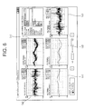
- FIG. 6 An example of the output by the display unit 62 on the display screen is shown in Fig. 6.
- graph (a) shows the data obtained in the tracking error calculating unit 58
- graph (b) shows the unfiltered speed data V
- graph (c) describes the data obtained in the displacement calculating unit 60
- graph (d) describes the digitally filtered speed data V
- graph (e) describes the data obtained in the acceleration calculating unit 59.
- the display unit 62 can also be configured to not only display one rotation of the optical disk D 's worth of data, but also display the distribution of the calculated amount of tracking error, displacement, acceleration, speed data, etc. in the optical disk D on the display screen to enable it to be grasped three-dimensionally.
- the tilt angle in the rotational direction (tangential skew) at a measuring position is calculated using the speed data V in a direction perpendicular to the data recording surface of the optical disk D detected by the laser Doppler speed meter 11 by noncontact means directly, the calculated value becomes very high in precision.
- the filter coefficients of the digital filtering unit 57 and the tracking error calculating unit 58 are calculated in accordance with the sampling rate Sr so that the filter characteristics become predetermined filter characteristics, the accuracy of each calculated value can be stabilized.
- the present embodiment it is possible to simultaneously calculate the perpendicular direction displacement, the acceleration, and the tracking error of the focus servo system using the speed data V used for the calculation of the tilt angle in the rotational direction.
- the acceleration can be calculated from the first order differential of the speed data V , it becomes possible to improve the accuracy compared with the case of calculating the acceleration from data of displacement in a direction perpendicular to the data recording surface of the optical disk D .
- the present invention is not limited to the above embodiment.
- the present invention can measure not only a data recording surface of an optical disk, but also, for example, the planar shape characteristics of a stamper which forms the data recording surface of an optical disk and which may become the cause of surface vibration of the data recording surface of the optical disk. Further, the present invention may also be applied for measuring the planar shape characteristics of a disk-shaped recording medium such as a magnetic disk other than an optical disk.
- the present invention it is possible to measure characteristics relating to the shape of a measured surface of a disk such as the data recording surface of an optical disk precisely and efficiently.
Landscapes
- Physics & Mathematics (AREA)
- General Physics & Mathematics (AREA)
- Manufacturing Optical Record Carriers (AREA)
- Optical Recording Or Reproduction (AREA)
- Length Measuring Devices By Optical Means (AREA)
- Optical Radar Systems And Details Thereof (AREA)
- Length Measuring Devices With Unspecified Measuring Means (AREA)
Abstract
Description
Claims (20)
- A planar shape characteristic measuring apparatus (1) comprising:a speed detecting means (11, 13) for detecting a perpendicular direction speed of a measured surface of a rotating disk anda tilt angle calculating means (61) for calculating a tilt angle in the rotational direction of said measured surface to a reference surface at each measuring position based on the linear speed at each measuring position detected by said speed detecting means (11, 13) and the detected perpendicular direction speed.
- A planar shape characteristic measuring apparatus (1) as set forth in claim 1, further comprising:a digital filtering means (57) for removing a noise component contained in speed data (52) detected by said speed detecting means (11, 13) anda filter coefficient calculating means (56) for calculating a filter coefficient in accordance with a sampling rate of said speed detecting means (11, 13) so that a filter characteristic of said digital filtering means (57) becomes a predetermined filter coefficient.
- A planar shape characteristic measuring apparatus (1) as set forth in claim 1, wherein said tilt angle calculating means (61) uses a value of said perpendicular direction speed divided by said linear speed as a tangent of said tilt angle and calculates said tilt angle by an inverse function of the tangent.
- A planar shape characteristic measuring apparatus (1) as set forth in claim 1, further comprising:a rotating means (2) for rotating said disk;a moving means (6, 8) for relatively moving said speed detecting means (11, 13) in the radial direction of said disk;an input means (53) for inputting a radius of said disk at a measuring position detected by said speed detecting means (11, 13) and a target linear speed at said measuring position; anda control means (51) for calculating a speed for rotating said disk based on the input radius and target linear speed, rotating said disk at the calculated speed, and outputting a control command for moving said speed detecting means (11, 13) to the measuring position of said input radius to said rotating means (2) and moving means (6, 8).
- A planar shape characteristic measuring apparatus (1) as set forth in claim 1, wherein said speed detecting means (11, 13) detects said perpendicular direction speed by a non-contact means at a measured surface of said disk.
- A planar shape characteristic measuring apparatus (1) as set forth in claim 5, wherein said speed detecting means (11, 13) comprises a laser Doppler speed meter (11).
- A planar shape characteristic measuring apparatus (1) as set forth in claim 1, wherein:said disk comprises a recording medium enabling at least one of optically recording and reproduction of information; andsaid measured surface comprises a data recording surface (104) of said recording medium.
- A planar shape characteristic measuring apparatus (1) as set forth in claim 1, further comprising:a displacement calculating means (60) for calculating a perpendicular direction displacement of said measured surface based on the detected perpendicular direction speed;an acceleration calculating means (59) for calculating a perpendicular direction acceleration of a measured surface of said disk at each detecting position based on the detected perpendicular direction speed; anda tracking error calculating means (58) for calculating an amount of tracking error which does not able tracking of unevenness of said measured surface predicted to occur in a servo system for making a predetermined object track a target position in a perpendicular direction from a measured surface of said rotating disk based on the detected perpendicular direction speed and a gain characteristic of said servo system.
- A planar shape characteristic measuring apparatus (1) as set forth in claim 8, wherein:said object is an optical pickup for performing at least one of recording of information onto a data recording surface (104) of said recording medium and reproduction of information from said data recording surface (104) or a lens mounted on said optical pickup; andsaid servo system comprises a focus servo system for making the focus of the optical pickup or the lens mounted on said optical pickup track a target position in a direction perpendicular to said data recording surface (104).
- A planar shape characteristic measuring apparatus (1) as set forth in claim 8, wherein said tracking error calculating means (58) comprises:a band-pass filter for removing high and low frequency noise components contained in detected perpendicular direction speed data andan integrator for integrating by time series the output from said band-pass filter.
- A planar shape characteristic measuring method comprising:a speed detecting step (S1, ..., S8) for detecting a perpendicular direction speed of a measured surface of a rotating disk anda tilt angle calculating step (S10) for calculating a tilt angle in the rotational direction of said measured surface with respect to a reference surface at each measuring position based on a linear speed of said measured surface at each measuring position and the detected perpendicular direction speed.
- A planar shape characteristic measuring method as set forth in claim 11, comprising:a filtering step (S9) for removing a noise component contained in speed data detected in said speed detecting step (S1, ..., S8) by a digital filter anda filter coefficient calculating step (S7) for calculating a filter coefficient in accordance with a sampling rate of said speed detecting step (S1, ..., S8) so that a filter characteristic of said digital filter becomes a predetermined filter characteristic.
- A planar shape characteristic measuring method as set forth in claim 11, wherein said tilt angle calculating step (S10) uses a value of said perpendicular direction speed divided by said linear speed as a tangent of said tilt angle and calculates said tilt angle by an inverse function of the tangent.
- A planar shape characteristic measuring method as set forth in claim 11, wherein said speed detecting step (S1, ..., S8) comprises:a step (S2) for inputting a radius of said disk at a measuring position and a target linear speed at said measuring position,a step (S5) for calculating a speed for rotating said disk based on the input radius and target linear speed and for rotating said disk at the calculated speed, anda step (S4) for moving a predetermined speed detecting means which detects said perpendicular direction speed to the measuring position of the input radius.
- A planar shape characteristic measuring method as set forth in claim 11, wherein said speed detecting step (S1, ..., S8) detects said perpendicular direction speed by a noncontact means at a measured surface of said disk.
- A planar shape characteristic measuring method as set forth in claim 15, wherein said speed detecting step (S1, ..., S8) detects said perpendicular direction speed by a laser Doppler speed meter.
- A planar shape characteristic measuring method as set forth in claim 11, wherein:a recording medium which enables at least one of optical recording and reproduction of information is used for said disk; andsaid measured surface comprises a data recording surface (104) of said recording medium.
- A planar shape characteristic measuring method as set forth in claim 11, further comprising:a displacement calculating step (S12) for calculating a perpendicular direction displacement of said measured surface based on the detected perpendicular direction speed;an acceleration calculating step (S14) for calculating a perpendicular direction acceleration of a measured surface of said disk at each detecting position based on the detected perpendicular direction speed; anda tracking error calculating step (S17) for calculating an amount of tracking error which does not able tracking of unevenness of said measured surface predicted to occur in a servo system for making a predetermined object track a target position in a perpendicular direction from a measured surface of said rotating disk based on the detected perpendicular direction speed and a gain characteristic of said servo system.
- A planar shape characteristic measuring method as set forth in claim 18, wherein:said object is an optical pickup for performing at least one of recording of information onto a data recording surface (104) of said recording medium and reproduction of information from said data recording surface (104) or a lens mounted on said optical pickup; andsaid servo system comprises a focus servo system for making the focus of the optical pickup or the lens mounted on said optical pickup track a target position in a direction perpendicular to said data recording surface.
- A planar shape characteristic measuring method as set forth in claim 18, wherein said tracking error calculating step (S17) removes high and low frequency noise components contained in the detected perpendicular direction speed data by a band-pass filter and calculates said amount of tracking error by integrating by time series the output from this band-pass filter.
Applications Claiming Priority (2)
| Application Number | Priority Date | Filing Date | Title |
|---|---|---|---|
| JP2000157944A JP2001330431A (en) | 2000-05-24 | 2000-05-24 | Surface shape characteristic measuring device and surface shape characteristic measuring method |
| JP2000157944 | 2000-05-24 |
Publications (2)
| Publication Number | Publication Date |
|---|---|
| EP1162610A2 true EP1162610A2 (en) | 2001-12-12 |
| EP1162610A3 EP1162610A3 (en) | 2003-01-02 |
Family
ID=18662486
Family Applications (1)
| Application Number | Title | Priority Date | Filing Date |
|---|---|---|---|
| EP01401363A Withdrawn EP1162610A3 (en) | 2000-05-24 | 2001-05-23 | Focus error correction from tilt measurement |
Country Status (3)
| Country | Link |
|---|---|
| US (1) | US6568289B2 (en) |
| EP (1) | EP1162610A3 (en) |
| JP (1) | JP2001330431A (en) |
Cited By (3)
| Publication number | Priority date | Publication date | Assignee | Title |
|---|---|---|---|---|
| WO2007000738A1 (en) * | 2005-06-29 | 2007-01-04 | Koninklijke Philips Electronics, N.V. | Tangential disc tilt measurement and corrective action |
| EP1638093A3 (en) * | 2004-09-18 | 2007-08-08 | Samsung Electronics Co., Ltd. | Tilt compensation method for optical recording/reproducing apparatus |
| CN103616007A (en) * | 2013-08-28 | 2014-03-05 | 西安工业大学 | Precision planeness-measuring apparatus for miniature part |
Families Citing this family (13)
| Publication number | Priority date | Publication date | Assignee | Title |
|---|---|---|---|---|
| SG126688A1 (en) * | 2002-01-15 | 2006-11-29 | Inst Data Storage | Active control system and method for reducing diskfluttering induced track misregistrations |
| JP4055072B2 (en) * | 2002-08-20 | 2008-03-05 | 株式会社リコー | Optical disc apparatus, tilt correction method, tilt control program, and recording medium recording this program |
| JP3962303B2 (en) * | 2002-08-30 | 2007-08-22 | 株式会社リコー | Optical disk device |
| WO2004064056A1 (en) * | 2003-01-10 | 2004-07-29 | Tdk Corporation | Method for inspecting optical recording medium |
| US7456968B2 (en) * | 2003-11-24 | 2008-11-25 | General Electric Company | Sensor system and methods for improved quantitation of environmental parameters |
| JP4509604B2 (en) * | 2004-03-05 | 2010-07-21 | 株式会社リコー | Shape data acquisition method and shape measuring apparatus |
| US20080024772A1 (en) * | 2006-07-26 | 2008-01-31 | Seagate Technology Llc | Particle removal tool with integrated defect detection/analysis capability |
| DE102007023826A1 (en) * | 2007-05-21 | 2008-11-27 | Polytec Gmbh | Method and device for non-contact vibration measurement |
| US7969674B2 (en) * | 2008-10-03 | 2011-06-28 | Seagate Technology Llc | Data transfer assembly performance characteristics testing |
| WO2010066695A1 (en) * | 2008-12-08 | 2010-06-17 | Imec | Method and apparatus for determining topography of an object |
| JP5184431B2 (en) * | 2009-04-28 | 2013-04-17 | シャープ株式会社 | MOCVD equipment |
| JP4810602B2 (en) * | 2009-12-04 | 2011-11-09 | シャープ株式会社 | Vapor growth apparatus and vapor growth method |
| CN109870130B (en) * | 2019-04-09 | 2024-07-02 | 中国科学技术大学 | Measuring method and device for detecting flatness of object by ultrasonic array |
Family Cites Families (7)
| Publication number | Priority date | Publication date | Assignee | Title |
|---|---|---|---|---|
| US4314763A (en) * | 1979-01-04 | 1982-02-09 | Rca Corporation | Defect detection system |
| JPS57161640A (en) * | 1981-03-31 | 1982-10-05 | Olympus Optical Co Ltd | Inspecting device for surface |
| US5983167A (en) * | 1996-05-29 | 1999-11-09 | Dainippon Ink And Chemicals, Inc. | Disc dishing measurement method and apparatus |
| JPH10177729A (en) | 1996-12-16 | 1998-06-30 | Nec Corp | Optical head tilt device |
| US5815255A (en) * | 1997-02-14 | 1998-09-29 | Medar, Inc. | Method and system for measuring deflection angle of a beam of light reflected from a disk to determine tilt of the disk |
| WO1999046603A1 (en) | 1998-03-09 | 1999-09-16 | Otm Technologies, Ltd. | Optical translation measurement |
| JP2000048384A (en) | 1998-07-27 | 2000-02-18 | Sony Corp | Apparatus and method for measuring runout of disc-shaped information recording medium |
-
2000
- 2000-05-24 JP JP2000157944A patent/JP2001330431A/en active Pending
-
2001
- 2001-05-21 US US09/860,498 patent/US6568289B2/en not_active Expired - Fee Related
- 2001-05-23 EP EP01401363A patent/EP1162610A3/en not_active Withdrawn
Cited By (4)
| Publication number | Priority date | Publication date | Assignee | Title |
|---|---|---|---|---|
| EP1638093A3 (en) * | 2004-09-18 | 2007-08-08 | Samsung Electronics Co., Ltd. | Tilt compensation method for optical recording/reproducing apparatus |
| WO2007000738A1 (en) * | 2005-06-29 | 2007-01-04 | Koninklijke Philips Electronics, N.V. | Tangential disc tilt measurement and corrective action |
| CN103616007A (en) * | 2013-08-28 | 2014-03-05 | 西安工业大学 | Precision planeness-measuring apparatus for miniature part |
| CN103616007B (en) * | 2013-08-28 | 2016-04-06 | 西安工业大学 | A kind of micro parts flatness precision measurement apparatus |
Also Published As
| Publication number | Publication date |
|---|---|
| US20020034151A1 (en) | 2002-03-21 |
| JP2001330431A (en) | 2001-11-30 |
| US6568289B2 (en) | 2003-05-27 |
| EP1162610A3 (en) | 2003-01-02 |
Similar Documents
| Publication | Publication Date | Title |
|---|---|---|
| US6568289B2 (en) | Planar shape characteristic measuring apparatus and planar shape characteristic measuring method | |
| EP0539354B1 (en) | Optical pickup apparatus | |
| JP2557896B2 (en) | Disk unit | |
| EP0334601B1 (en) | Error detecting device for optical head | |
| KR100529986B1 (en) | Light integration unit, optical pickup device using the unit, and optical disk device | |
| US5640377A (en) | Rotation information detecting apparatus and method | |
| US7050379B2 (en) | Optical pickup-use object lens, optical pickup and optical disk unit | |
| JPH059866B2 (en) | ||
| Komma et al. | Dual focus optical head with a hologram-integrated lens | |
| WO2004088656A1 (en) | Disc drive apparatus, and method for recognizing cd and dvd | |
| JP2000348423A (en) | Apparatus and method for measuring characteristics of disk-shaped recording medium | |
| EP1150286B1 (en) | Near-field optical head | |
| JP2624720B2 (en) | Information recording / reproducing device | |
| KR100200827B1 (en) | Information recording and reproducing apparatus and the method thereof for optical disc | |
| JPH1083580A (en) | Optical disk measuring device | |
| JP2000048384A (en) | Apparatus and method for measuring runout of disc-shaped information recording medium | |
| US20060215521A1 (en) | Disc drive apparatus | |
| JPH11259872A (en) | Optical disc device, distance detecting device and detecting method used for the same | |
| JPH04258819A (en) | Optical disk device | |
| KR100712895B1 (en) | Method for correcting spherical aberration of optical disc and suitable device | |
| JP3975539B2 (en) | Optical disk device | |
| JPS60231930A (en) | Reproducing device for optical recording disk | |
| JPS61239440A (en) | Optical information recording and reproducing device | |
| JP2003132587A (en) | Optical recording medium and its evaluation method | |
| JP2005518617A (en) | Apparatus and method for measuring pitch of local track |
Legal Events
| Date | Code | Title | Description |
|---|---|---|---|
| PUAI | Public reference made under article 153(3) epc to a published international application that has entered the european phase |
Free format text: ORIGINAL CODE: 0009012 |
|
| AK | Designated contracting states |
Kind code of ref document: A2 Designated state(s): AT BE CH CY DE DK ES FI FR GB GR IE IT LI LU MC NL PT SE TR |
|
| AX | Request for extension of the european patent |
Free format text: AL;LT;LV;MK;RO;SI |
|
| PUAL | Search report despatched |
Free format text: ORIGINAL CODE: 0009013 |
|
| AK | Designated contracting states |
Kind code of ref document: A3 Designated state(s): AT BE CH CY DE DK ES FI FR GB GR IE IT LI LU MC NL PT SE TR |
|
| AX | Request for extension of the european patent |
Free format text: AL;LT;LV;MK;RO;SI |
|
| RIC1 | Information provided on ipc code assigned before grant |
Free format text: 7G 11B 7/095 A, 7G 01P 3/00 B |
|
| 17P | Request for examination filed |
Effective date: 20030701 |
|
| AKX | Designation fees paid |
Designated state(s): DE FR GB NL |
|
| STAA | Information on the status of an ep patent application or granted ep patent |
Free format text: STATUS: THE APPLICATION HAS BEEN WITHDRAWN |
|
| 18W | Application withdrawn |
Effective date: 20040116 |