EP1162352A2 - Plasma-catalyst control system - Google Patents
Plasma-catalyst control system Download PDFInfo
- Publication number
- EP1162352A2 EP1162352A2 EP01304963A EP01304963A EP1162352A2 EP 1162352 A2 EP1162352 A2 EP 1162352A2 EP 01304963 A EP01304963 A EP 01304963A EP 01304963 A EP01304963 A EP 01304963A EP 1162352 A2 EP1162352 A2 EP 1162352A2
- Authority
- EP
- European Patent Office
- Prior art keywords
- engine
- plasma
- exhaust
- operating variable
- concentration
- Prior art date
- Legal status (The legal status is an assumption and is not a legal conclusion. Google has not performed a legal analysis and makes no representation as to the accuracy of the status listed.)
- Withdrawn
Links
Images

Classifications
-
- F—MECHANICAL ENGINEERING; LIGHTING; HEATING; WEAPONS; BLASTING
- F01—MACHINES OR ENGINES IN GENERAL; ENGINE PLANTS IN GENERAL; STEAM ENGINES
- F01N—GAS-FLOW SILENCERS OR EXHAUST APPARATUS FOR MACHINES OR ENGINES IN GENERAL; GAS-FLOW SILENCERS OR EXHAUST APPARATUS FOR INTERNAL-COMBUSTION ENGINES
- F01N3/00—Exhaust or silencing apparatus having means for purifying, rendering innocuous, or otherwise treating exhaust
- F01N3/08—Exhaust or silencing apparatus having means for purifying, rendering innocuous, or otherwise treating exhaust for rendering innocuous
- F01N3/10—Exhaust or silencing apparatus having means for purifying, rendering innocuous, or otherwise treating exhaust for rendering innocuous by thermal or catalytic conversion of noxious components of exhaust
- F01N3/18—Exhaust or silencing apparatus having means for purifying, rendering innocuous, or otherwise treating exhaust for rendering innocuous by thermal or catalytic conversion of noxious components of exhaust characterised by methods of operation; Control
- F01N3/20—Exhaust or silencing apparatus having means for purifying, rendering innocuous, or otherwise treating exhaust for rendering innocuous by thermal or catalytic conversion of noxious components of exhaust characterised by methods of operation; Control specially adapted for catalytic conversion
-
- B—PERFORMING OPERATIONS; TRANSPORTING
- B01—PHYSICAL OR CHEMICAL PROCESSES OR APPARATUS IN GENERAL
- B01D—SEPARATION
- B01D53/00—Separation of gases or vapours; Recovering vapours of volatile solvents from gases; Chemical or biological purification of waste gases, e.g. engine exhaust gases, smoke, fumes, flue gases, aerosols
- B01D53/34—Chemical or biological purification of waste gases
- B01D53/74—General processes for purification of waste gases; Apparatus or devices specially adapted therefor
- B01D53/86—Catalytic processes
- B01D53/8696—Controlling the catalytic process
-
- B—PERFORMING OPERATIONS; TRANSPORTING
- B01—PHYSICAL OR CHEMICAL PROCESSES OR APPARATUS IN GENERAL
- B01D—SEPARATION
- B01D53/00—Separation of gases or vapours; Recovering vapours of volatile solvents from gases; Chemical or biological purification of waste gases, e.g. engine exhaust gases, smoke, fumes, flue gases, aerosols
- B01D53/34—Chemical or biological purification of waste gases
- B01D53/92—Chemical or biological purification of waste gases of engine exhaust gases
- B01D53/94—Chemical or biological purification of waste gases of engine exhaust gases by catalytic processes
- B01D53/9495—Controlling the catalytic process
-
- F—MECHANICAL ENGINEERING; LIGHTING; HEATING; WEAPONS; BLASTING
- F01—MACHINES OR ENGINES IN GENERAL; ENGINE PLANTS IN GENERAL; STEAM ENGINES
- F01N—GAS-FLOW SILENCERS OR EXHAUST APPARATUS FOR MACHINES OR ENGINES IN GENERAL; GAS-FLOW SILENCERS OR EXHAUST APPARATUS FOR INTERNAL-COMBUSTION ENGINES
- F01N3/00—Exhaust or silencing apparatus having means for purifying, rendering innocuous, or otherwise treating exhaust
- F01N3/08—Exhaust or silencing apparatus having means for purifying, rendering innocuous, or otherwise treating exhaust for rendering innocuous
- F01N3/0892—Electric or magnetic treatment, e.g. dissociation of noxious components
-
- F—MECHANICAL ENGINEERING; LIGHTING; HEATING; WEAPONS; BLASTING
- F01—MACHINES OR ENGINES IN GENERAL; ENGINE PLANTS IN GENERAL; STEAM ENGINES
- F01N—GAS-FLOW SILENCERS OR EXHAUST APPARATUS FOR MACHINES OR ENGINES IN GENERAL; GAS-FLOW SILENCERS OR EXHAUST APPARATUS FOR INTERNAL-COMBUSTION ENGINES
- F01N3/00—Exhaust or silencing apparatus having means for purifying, rendering innocuous, or otherwise treating exhaust
- F01N3/08—Exhaust or silencing apparatus having means for purifying, rendering innocuous, or otherwise treating exhaust for rendering innocuous
- F01N3/10—Exhaust or silencing apparatus having means for purifying, rendering innocuous, or otherwise treating exhaust for rendering innocuous by thermal or catalytic conversion of noxious components of exhaust
- F01N3/18—Exhaust or silencing apparatus having means for purifying, rendering innocuous, or otherwise treating exhaust for rendering innocuous by thermal or catalytic conversion of noxious components of exhaust characterised by methods of operation; Control
- F01N3/20—Exhaust or silencing apparatus having means for purifying, rendering innocuous, or otherwise treating exhaust for rendering innocuous by thermal or catalytic conversion of noxious components of exhaust characterised by methods of operation; Control specially adapted for catalytic conversion
- F01N3/2006—Periodically heating or cooling catalytic reactors, e.g. at cold starting or overheating
- F01N3/2013—Periodically heating or cooling catalytic reactors, e.g. at cold starting or overheating using electric or magnetic heating means
-
- B—PERFORMING OPERATIONS; TRANSPORTING
- B01—PHYSICAL OR CHEMICAL PROCESSES OR APPARATUS IN GENERAL
- B01D—SEPARATION
- B01D2259/00—Type of treatment
- B01D2259/80—Employing electric, magnetic, electromagnetic or wave energy, or particle radiation
- B01D2259/818—Employing electrical discharges or the generation of a plasma
-
- F—MECHANICAL ENGINEERING; LIGHTING; HEATING; WEAPONS; BLASTING
- F01—MACHINES OR ENGINES IN GENERAL; ENGINE PLANTS IN GENERAL; STEAM ENGINES
- F01N—GAS-FLOW SILENCERS OR EXHAUST APPARATUS FOR MACHINES OR ENGINES IN GENERAL; GAS-FLOW SILENCERS OR EXHAUST APPARATUS FOR INTERNAL-COMBUSTION ENGINES
- F01N2570/00—Exhaust treating apparatus eliminating, absorbing or adsorbing specific elements or compounds
- F01N2570/14—Nitrogen oxides
-
- Y—GENERAL TAGGING OF NEW TECHNOLOGICAL DEVELOPMENTS; GENERAL TAGGING OF CROSS-SECTIONAL TECHNOLOGIES SPANNING OVER SEVERAL SECTIONS OF THE IPC; TECHNICAL SUBJECTS COVERED BY FORMER USPC CROSS-REFERENCE ART COLLECTIONS [XRACs] AND DIGESTS
- Y02—TECHNOLOGIES OR APPLICATIONS FOR MITIGATION OR ADAPTATION AGAINST CLIMATE CHANGE
- Y02A—TECHNOLOGIES FOR ADAPTATION TO CLIMATE CHANGE
- Y02A50/00—TECHNOLOGIES FOR ADAPTATION TO CLIMATE CHANGE in human health protection, e.g. against extreme weather
- Y02A50/20—Air quality improvement or preservation, e.g. vehicle emission control or emission reduction by using catalytic converters
-
- Y—GENERAL TAGGING OF NEW TECHNOLOGICAL DEVELOPMENTS; GENERAL TAGGING OF CROSS-SECTIONAL TECHNOLOGIES SPANNING OVER SEVERAL SECTIONS OF THE IPC; TECHNICAL SUBJECTS COVERED BY FORMER USPC CROSS-REFERENCE ART COLLECTIONS [XRACs] AND DIGESTS
- Y02—TECHNOLOGIES OR APPLICATIONS FOR MITIGATION OR ADAPTATION AGAINST CLIMATE CHANGE
- Y02T—CLIMATE CHANGE MITIGATION TECHNOLOGIES RELATED TO TRANSPORTATION
- Y02T10/00—Road transport of goods or passengers
- Y02T10/10—Internal combustion engine [ICE] based vehicles
- Y02T10/12—Improving ICE efficiencies
Definitions
- This invention relates to plasma-catalyst systems and, more particularly, to a control system for reducing electrical power consumption in a plasma-catalyst system.
- Certain compounds in the exhaust stream of a combustion process are undesirable and must be controlled in order to and meet government emissions regulations.
- the regulated compounds are hydrocarbons, soot particulates, and nitrogen oxide compounds (NO x ).
- NO x nitrogen oxide compounds
- combustion processes producing these emissions for instance, coal or oil-fired furnaces, reciprocating internal combustion engines (including gasoline spark ignition and diesel engines), gas turbine engines, and so on. In each of these combustion processes, control measures to prevent or diminish atmospheric emissions of these emissions are needed.
- a catalytic converter in the exhaust system of gasoline spark ignition engines to remove undesirable emissions from the exhaust by chemical treatment.
- a "three-way" catalyst system of platinum, palladium, and/or rhodium metals dispersed on an oxide support is used to oxidise carbon monoxide and hydrocarbons to water and carbon dioxide and to reduce nitrogen oxides to nitrogen.
- the catalyst system is applied to a ceramic substrate such as beads, pellets, or a monolith. When used, beads are usually porous, ceramic spheres having the catalyst metals impregnated in an outer shell.
- the beads or pellets are of a suitable size and number in the catalytic converter in order to place an aggregate surface area in contact with the exhaust stream that is sufficient to treat the compounds of interest.
- a monolith When a monolith is used, it is usually a cordierite honeycomb monolith and may be pre-coated with .gamma.-alumina and other speciality oxide materials to provide a durable, high surface area support phase for catalyst deposition.
- the honeycomb shape used with the parallel channels running in the direction of the flow of the exhaust stream, both increases the surface area exposed to the exhaust stream and allows the exhaust stream to pass through the catalytic converter without creating undue back pressure that would interfere with operation of the engine.
- the exhaust stream from a diesel engine also has a substantial oxygen content, from perhaps about 2-18% oxygen, and, in addition, contains a significant amount of particulate emissions.
- the particulate emissions, or soot are thought to be primarily carbonaceous particles. It is also believed that other combustion processes result in emissions that are difficult or expensive to control because of, for instance, dilute concentrations of the compounds to be removed from the effluent stream or poor conversion of the compounds using conventional means.
- An alternative way to treat the hydrocarbon, particulate, or NO x emissions in an exhaust or effluent stream would be to destroy such emissions using a non-thermal plasma combined with a suitable catalyst (plasma-catalyst). It is known that plasma-catalyst reactors are useful to treat NO x and SO x emissions in power plant flue gases, and even to treat NO x or particulate emissions in diesel engine exhaust.
- plasma-catalyst reactors are useful to treat NO x and SO x emissions in power plant flue gases, and even to treat NO x or particulate emissions in diesel engine exhaust.
- systems now known in the art suffer from serious shortcomings. For example, such systems are run continually, which results in relatively large power consumption per unit of material destroyed, particularly when used to treat low concentration of emissions in effluent or exhaust streams.
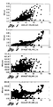
- Figures 1 and 2 show NO x mass flow rate (g/s) for each second during the FTP and MVEURO cycles respectively, plotted against measured exhaust volume flow (L/s). It can be seen that there is little relation between the two.
- Figures 3 and 4 show NO x concentration (ppm) versus exhaust flow. Here, it can be seen that there are modes with high exhaust flow but low NO x concentration. The present invention is directed to taking advantage of these relationships to reduce electrical power consumption by reducing plasma power during such modes.
- a system and method of controlling power to a plasma-catalyst that controls the plasma power in accordance with either measured or estimated values of engine or vehicle operational parameters in order to optimise emission reduction versus energy cost.
- a basic strategy delivers a constant energy to the plasma per standard volume (or mass) of engine exhaust, usually expressed as constant J/L. This improves energy efficiency over a constant plasma power delivery since the chemical conversion of a plasma-catalyst system is well known to vary with energy per volume, usually measured in Joules energy per Litre of exhaust.
- An added strategy varies the J/L energy delivery in relation to a measured or estimated value of a relevant parameter.
- engine-out and/or tailpipe NO x concentration is measured or estimated, and under conditions of high NO x production, higher energy deposition is commanded; while under lower NO x conditions, lower energy is commanded. This results in an improved energy cost versus emission performance.
- Figure 5 shows predicted NO x conversion efficiency versus FE loss, counting both electrical and HC addition costs, with lines for various HC:NO x ratios (HC is measured in ppmC1). Along each line, the plasma power deposition (J/L) is varied from 0 to 25 J/L. A base condition of 5.5:1 HC:NO x ratio, and 15 J/L plasma energy was chosen.
- the HC:NO x ratio needed for best NO x control is higher than is likely to exist in engine-out exhaust without some form of control to increase it.
- Various systems have been proposed to add (inject) fuel to the exhaust or employ a "post-injection" strategy, where fuel is injected in the engine late in the cycle (exhaust stroke) so that it does not get completely burned. Either of these strategies may be employed where needed to achieve the desired HC:NO x ratio.
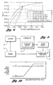
- Figure 6 shows a plot similar to Figure 5, with lines representing different plasma power strategies.
- Plot A depicts a strategy of turning off plasma power at low space velocity (SV).
- the space velocity SV corresponds to the amount of exhaust gases flowing per unit time period.
- the plasma power is turned off.
- the selected level varies along the line; the upper right selects a level of zero, i.e., no cut-off.
- Plot B depicts a strategy of turning off plasma power at high SV.
- the plasma power is turned off.
- the selected level varies along the line; the upper right selects a level of 1000, i.e., no cut-off.
- Plot C depicts a strategy of turning off plasma power at low NO x ppm.
- the plasma power is turned off.
- the selected level varies along the line; the upper right selects a level of zero, i.e., no cut-off.
- Plot D depicts a strategy of turning off plasma power at high NO x ppm.
- the plasma power is turned off.
- the selected level varies along the line; the upper right selects a level of 1000, i.e., no cut-off.
- Plot E depicts a strategy of 1 ⁇ 2 plasma power at low ppm NO x . This strategy is similar to that depicted in Plot C, except instead of turning the power off completely, the power is turned down by a factor of 2.
- Plot F depicts a strategy similar to that shown in Plot E, expect the base power is 23 J/L rather than 15 J/L as with all other lines in the Figure 6.
- FIG. 9 a schematic block diagram of the invention for implementing a strategy of plasma power reduction is shown.
- An engine 10 is controlled by a controller 12 which reads a set of sensors 14 providing measured values of engine operating conditions.
- the sensors 14 include at least a subset of
- the measured values read into the controller 12 may be used to calculate estimated values that are not measured directly.
- engine-out exhaust temperature can be estimated from fuel delivery, engine speed, and coolant temperature.
- programmed values of exhaust component thermal mass can be added to generate a calculated value of catalyst substrate temperature.
- estimated values of engine-out emissions can be calculated based on measured values. These calculations can be made by regression analysis of test laboratory data, or from first principles models. They can be embodied in a controller in the form of equations, tables, logic diagrams, neural net control algorithms, etc.
- catalyst temperature in current gasoline engine vehicles is estimated from other measured values.
- controls can be based in these indirect measurements without explicit calculation of the variable.
- plasma power J/L can be modulated with a load parameter such as fuel charge per cylinder filling which may closely correlate with emission concentration, without actually calculating the emission concentration.
- the power supply 16 can be either of the pulsed and continuous wave type.
- the energy per pulse can be varied (by varying the voltage amplitude and/or duration), and the pulse period can be reduced (more pulses per unit time).
- the energy can be controlled by controlling the voltage amplitude, or frequency.
- a typical strategy is shown in Figure 10 where a constant energy is delivered to the plasma per standard volume (or mass) of engine exhaust. This corresponds to Line A in the plot. In so doing, energy efficiency is improved since the chemical conversion of a plasma-catalyst system varies with energy per volume, usually measured in Joules energy per Litre of exhaust.
- Another strategy varies the J/L energy delivery in relation to a measured or estimated value of a relevant engine operating parameter, such as for example, engine-out and/or tailpipe NO x concentration.
- This strategy corresponds to Line B in the plot of Figure 10.
- higher energy deposition is commanded, while under lower NO x conditions lower energy is commanded. This results in an improved energy cost versus emission performance, as shown on the graphs of Figures 5-8.
- Engine power may be estimated by engine LOAD which may be calculated as engine air flow per cylinder filling airflow per cylinder at maximum load
- the numerator is calculated from an air meter (corrected for dynamic effects) and engine speed.
- the denominator is a parameter measured in the dynamometer lab and stored as a function of RPM, then corrected for barometric pressure.
- the parameter LOAD is well correlated with engine indicated torque. Simply multiplying torque by RPM would provide an indication of engine power.
Landscapes
- Engineering & Computer Science (AREA)
- Chemical & Material Sciences (AREA)
- Chemical Kinetics & Catalysis (AREA)
- Health & Medical Sciences (AREA)
- Combustion & Propulsion (AREA)
- Environmental & Geological Engineering (AREA)
- Toxicology (AREA)
- Mechanical Engineering (AREA)
- General Engineering & Computer Science (AREA)
- Biomedical Technology (AREA)
- Analytical Chemistry (AREA)
- General Chemical & Material Sciences (AREA)
- Oil, Petroleum & Natural Gas (AREA)
- Exhaust Gas After Treatment (AREA)
Abstract
Description
- Engine position or speed
- Throttle or accelerator pedal position
- Air flow
- Manifold pressure
- Temperature (coolant, oil, and/or air)
- Fuel flow
- Exhaust composition including pollutants, before and/or after the plasma-catalyst device
- Any other available engine or vehicle operational parameter which can be sensed.
Claims (10)
- A method of controlling power to a plasma-catalyst comprising a sequence of the steps of:measuring vehicle operating parameters;determining the value of at least one predetermined engine operating variable from the measured operating parameters;controlling a power supply of at least one plasma-catalyst reactor to vary the power supplied to the plasma as a function of said operating variable to control emission reduction while reducing energy cost.
- The method of Claim 1 wherein the engine operating variable is the volume of engine exhaust and the power supply is controlled to deliver a constant energy to the plasma of the reactor as a function of the volume of engine exhaust (J/L).
- The method of Claim 1 wherein the engine operating variable is engine-out NOx concentration.
- The method of Claim 1 wherein the engine operating variable is tailpipe NOx concentration.
- The method of Claim 1 wherein the engine operating variable is a combination of engine-out NOx concentration and tailpipe NOx concentration.
- The method of Claim 1 wherein the engine operating variable is engine output power.
- The method of Claim 1 wherein the engine operating variable is particulate mass generation.
- A system for controlling power to a plasma-catalyst comprising:a plurality of sensors for measuring vehicle operating parameters;a computer for determining the value of at least one predetermined engine operating variable from the measured operating parameters;said computer means controlling the output of a power supply of at least one plasma-catalyst reactor as a function of said operating variable to control emission reduction.
- The system of Claim 8 wherein the engine operating variable is the volume of engine exhaust and the power supply is controlled to deliver a constant energy to the plasma of the reactor as a function of the volume of engine exhaust.
- The system of Claim 8 wherein the engine operating variable is engine-out NOx concentration.
Applications Claiming Priority (2)
| Application Number | Priority Date | Filing Date | Title |
|---|---|---|---|
| US09/590,984 US6363714B1 (en) | 2000-06-09 | 2000-06-09 | Plasma-catalyst control system |
| US590984 | 2000-06-09 |
Publications (2)
| Publication Number | Publication Date |
|---|---|
| EP1162352A2 true EP1162352A2 (en) | 2001-12-12 |
| EP1162352A3 EP1162352A3 (en) | 2003-06-04 |
Family
ID=24364540
Family Applications (1)
| Application Number | Title | Priority Date | Filing Date |
|---|---|---|---|
| EP01304963A Withdrawn EP1162352A3 (en) | 2000-06-09 | 2001-06-06 | Plasma-catalyst control system |
Country Status (3)
| Country | Link |
|---|---|
| US (1) | US6363714B1 (en) |
| EP (1) | EP1162352A3 (en) |
| JP (1) | JP2002021542A (en) |
Cited By (2)
| Publication number | Priority date | Publication date | Assignee | Title |
|---|---|---|---|---|
| EP2075422A1 (en) | 2007-12-25 | 2009-07-01 | Kabushiki Kaisha Toyota Jidoshokki | Exhaust gas treatment system for an internal combustion engine |
| DE102006032722B4 (en) * | 2005-07-14 | 2013-08-08 | Honda Motor Co., Ltd. | exhaust gas purification device |
Families Citing this family (6)
| Publication number | Priority date | Publication date | Assignee | Title |
|---|---|---|---|---|
| KR20030092386A (en) * | 2002-05-29 | 2003-12-06 | 현대자동차주식회사 | System for decreasing in exhaust gas for vehicles having plasma reactor and method for controlling the same |
| AT413738B (en) * | 2004-02-09 | 2006-05-15 | Ge Jenbacher Gmbh & Co Ohg | METHOD FOR REGULATING A COMBUSTION ENGINE |
| AT413739B (en) * | 2004-02-09 | 2006-05-15 | Ge Jenbacher Gmbh & Co Ohg | METHOD FOR REGULATING A COMBUSTION ENGINE |
| US7454895B2 (en) * | 2004-03-19 | 2008-11-25 | Ford Global Technologies, Llc | Diagnosing an aftertreatment system with a nonthermal plasma discharge device coupled to a lean burn engine |
| US7114324B2 (en) * | 2004-03-19 | 2006-10-03 | Ford Global Technologies, Llc | Method for operating a lean burn engine with an aftertreatment system including nonthermal plasma discharge device |
| JP2005291071A (en) * | 2004-03-31 | 2005-10-20 | Honda Motor Co Ltd | Exhaust gas purification system and exhaust gas purification method |
Family Cites Families (15)
| Publication number | Priority date | Publication date | Assignee | Title |
|---|---|---|---|---|
| JPH04243525A (en) * | 1991-01-22 | 1992-08-31 | Toyota Motor Corp | Apparatus for purifying exhaust gas of internal combustion engine |
| JP2738251B2 (en) * | 1993-01-20 | 1998-04-08 | 松下電器産業株式会社 | Filter regeneration device for internal combustion engine |
| US5419123A (en) * | 1993-03-29 | 1995-05-30 | Unlimited Technologies, Inc. | Emission control device and method |
| US5549795A (en) * | 1994-08-25 | 1996-08-27 | Hughes Aircraft Company | Corona source for producing corona discharge and fluid waste treatment with corona discharge |
| US5695619A (en) | 1995-05-25 | 1997-12-09 | Hughes Aircraft | Gaseous pollutant destruction method using self-resonant corona discharge |
| US6038854A (en) * | 1996-08-19 | 2000-03-21 | The Regents Of The University Of California | Plasma regenerated particulate trap and NOx reduction system |
| US5822981A (en) * | 1996-08-19 | 1998-10-20 | Hughes Electronics Corporation | Automatic control system and method for corona discharge pollutant destruction apparatus |
| US5711147A (en) * | 1996-08-19 | 1998-01-27 | The Regents Of The University Of California | Plasma-assisted catalytic reduction system |
| US5866081A (en) | 1996-08-19 | 1999-02-02 | Hughes Electronics Corporation | Deposited inner electrode for corona discharge pollutant destruction reactor |
| US6038853A (en) * | 1996-08-19 | 2000-03-21 | The Regents Of The University Of California | Plasma-assisted catalytic storage reduction system |
| US5807466A (en) | 1996-08-19 | 1998-09-15 | Hughes Electronics | Fuel injection system and method for treatment of NOx in a corona discharge pollutant destruction apparatus |
| US5836154A (en) | 1996-08-19 | 1998-11-17 | Raytheon Company | Multi-state gaseous pollutant destruction apparatus and method |
| US6047543A (en) * | 1996-12-18 | 2000-04-11 | Litex, Inc. | Method and apparatus for enhancing the rate and efficiency of gas phase reactions |
| JPH11324652A (en) * | 1998-04-09 | 1999-11-26 | Fev Motorentechnik Gmbh & Co Kg | Method for reducing emission of harmful matter from automobile |
| US6176078B1 (en) * | 1998-11-13 | 2001-01-23 | Engelhard Corporation | Plasma fuel processing for NOx control of lean burn engines |
-
2000
- 2000-06-09 US US09/590,984 patent/US6363714B1/en not_active Expired - Fee Related
-
2001
- 2001-04-24 JP JP2001125646A patent/JP2002021542A/en active Pending
- 2001-06-06 EP EP01304963A patent/EP1162352A3/en not_active Withdrawn
Cited By (2)
| Publication number | Priority date | Publication date | Assignee | Title |
|---|---|---|---|---|
| DE102006032722B4 (en) * | 2005-07-14 | 2013-08-08 | Honda Motor Co., Ltd. | exhaust gas purification device |
| EP2075422A1 (en) | 2007-12-25 | 2009-07-01 | Kabushiki Kaisha Toyota Jidoshokki | Exhaust gas treatment system for an internal combustion engine |
Also Published As
| Publication number | Publication date |
|---|---|
| EP1162352A3 (en) | 2003-06-04 |
| JP2002021542A (en) | 2002-01-23 |
| US6363714B1 (en) | 2002-04-02 |
Similar Documents
| Publication | Publication Date | Title |
|---|---|---|
| US7165393B2 (en) | System and methods for improved emission control of internal combustion engines | |
| US7082753B2 (en) | System and methods for improved emission control of internal combustion engines using pulsed fuel flow | |
| EP0786284B1 (en) | A catalyst system | |
| KR102602970B1 (en) | Exhaust gas after-treatment system and method for the exhaust gas after-treatment of an internal combustion engine | |
| EP1444430B1 (en) | Exhaust gas purifying device and method for internal combustion engine | |
| CN101149011B (en) | Apparatus to inject a reductant into an exhaust gas feedstream | |
| CN101379279B (en) | Method and apparatus for operating a methane-fuelled engine and treating exhaust gas with a methane oxidation catalyst | |
| CN101929374A (en) | Passive ammonia-selective catalytic reduction for NOx control in internal combustion engines | |
| US6845612B2 (en) | NOx-reducing catalyst with temperature regulation of exhaust gas | |
| US20170159533A1 (en) | Systems and methods for determining the quantity of a combustion product in a vehicle exhaust | |
| Zheng et al. | Energy efficiency analyses of active flow aftertreatment systems for lean burn internal combustion engines | |
| US8381513B2 (en) | Internal combustion engine system | |
| US6363714B1 (en) | Plasma-catalyst control system | |
| US7654076B2 (en) | System for controlling absorber regeneration | |
| US20160061129A1 (en) | System and method of recovering oxidation catalyst performance | |
| JP2009513868A (en) | Device for treating nitric oxide in automobile exhaust gas | |
| Suresh et al. | Diesel particulate filter system-effect of critical variables on the regeneration strategy development and optimization | |
| US6568174B2 (en) | Process and apparatus for reducing warm-up emissions of a direct injection internal combustion engine | |
| EP1857648B1 (en) | System and methods for improving emission control of internal combustion engines | |
| US20050204724A1 (en) | Method for operating a lean burn engine with an aftertreatment system including nonthermal plasma discharge device | |
| Wada et al. | Study on Emission Reducing Method with New Lean NOx Catalyst for Diesel Engines | |
| Iwasaki et al. | Development and evaluation of catalysts to remove NOx from diesel engine exhaust gas | |
| EP4643001A1 (en) | Low carbon combustion engine | |
| Li et al. | NOx emission aftertreatment study on lean burn gasoline engine using adsorber reduction catalyst | |
| JP5698706B2 (en) | Internal combustion engine system |
Legal Events
| Date | Code | Title | Description |
|---|---|---|---|
| PUAI | Public reference made under article 153(3) epc to a published international application that has entered the european phase |
Free format text: ORIGINAL CODE: 0009012 |
|
| AK | Designated contracting states |
Kind code of ref document: A2 Designated state(s): AT BE CH CY DE DK ES FI FR GB GR IE IT LI LU MC NL PT SE TR |
|
| AX | Request for extension of the european patent |
Free format text: AL;LT;LV;MK;RO;SI |
|
| PUAL | Search report despatched |
Free format text: ORIGINAL CODE: 0009013 |
|
| RIC1 | Information provided on ipc code assigned before grant |
Ipc: 7F 01N 3/01 B Ipc: 7B 01D 53/94 B Ipc: 7F 01N 3/20 B Ipc: 7B 01D 53/32 B Ipc: 7F 01N 3/08 A |
|
| AK | Designated contracting states |
Designated state(s): AT BE CH CY DE DK ES FI FR GB GR IE IT LI LU MC NL PT SE TR |
|
| AX | Request for extension of the european patent |
Extension state: AL LT LV MK RO SI |
|
| 17P | Request for examination filed |
Effective date: 20031129 |
|
| AKX | Designation fees paid |
Designated state(s): DE FR GB |
|
| 17Q | First examination report despatched |
Effective date: 20040210 |
|
| STAA | Information on the status of an ep patent application or granted ep patent |
Free format text: STATUS: THE APPLICATION IS DEEMED TO BE WITHDRAWN |
|
| 18D | Application deemed to be withdrawn |
Effective date: 20070103 |