EP1162283A2 - Friction stir grain refinement of structural members - Google Patents
Friction stir grain refinement of structural members Download PDFInfo
- Publication number
- EP1162283A2 EP1162283A2 EP01202071A EP01202071A EP1162283A2 EP 1162283 A2 EP1162283 A2 EP 1162283A2 EP 01202071 A EP01202071 A EP 01202071A EP 01202071 A EP01202071 A EP 01202071A EP 1162283 A2 EP1162283 A2 EP 1162283A2
- Authority
- EP
- European Patent Office
- Prior art keywords
- structural member
- region
- structural
- high operational
- regions
- Prior art date
- Legal status (The legal status is an assumption and is not a legal conclusion. Google has not performed a legal analysis and makes no representation as to the accuracy of the status listed.)
- Granted
Links
- 238000003756 stirring Methods 0.000 title claims abstract description 36
- 239000000523 sample Substances 0.000 claims abstract description 71
- 238000003466 welding Methods 0.000 claims abstract description 35
- 238000000034 method Methods 0.000 claims abstract description 31
- 239000000463 material Substances 0.000 claims abstract description 26
- 238000005266 casting Methods 0.000 claims abstract description 10
- 238000002156 mixing Methods 0.000 claims description 30
- 229910045601 alloy Inorganic materials 0.000 claims description 10
- 239000000956 alloy Substances 0.000 claims description 10
- 229910000881 Cu alloy Inorganic materials 0.000 claims description 9
- FYYHWMGAXLPEAU-UHFFFAOYSA-N Magnesium Chemical compound [Mg] FYYHWMGAXLPEAU-UHFFFAOYSA-N 0.000 claims description 9
- 229910052782 aluminium Inorganic materials 0.000 claims description 9
- XAGFODPZIPBFFR-UHFFFAOYSA-N aluminium Chemical compound [Al] XAGFODPZIPBFFR-UHFFFAOYSA-N 0.000 claims description 9
- 238000003754 machining Methods 0.000 claims description 9
- 239000011777 magnesium Substances 0.000 claims description 9
- 229910052749 magnesium Inorganic materials 0.000 claims description 9
- 238000004881 precipitation hardening Methods 0.000 claims description 8
- 229910001369 Brass Inorganic materials 0.000 claims description 5
- RYGMFSIKBFXOCR-UHFFFAOYSA-N Copper Chemical compound [Cu] RYGMFSIKBFXOCR-UHFFFAOYSA-N 0.000 claims description 5
- 229910000831 Steel Inorganic materials 0.000 claims description 5
- RTAQQCXQSZGOHL-UHFFFAOYSA-N Titanium Chemical compound [Ti] RTAQQCXQSZGOHL-UHFFFAOYSA-N 0.000 claims description 5
- 239000010951 brass Substances 0.000 claims description 5
- 229910052802 copper Inorganic materials 0.000 claims description 5
- 239000010949 copper Substances 0.000 claims description 5
- 229910001220 stainless steel Inorganic materials 0.000 claims description 5
- 239000010935 stainless steel Substances 0.000 claims description 5
- 239000010959 steel Substances 0.000 claims description 5
- 239000010936 titanium Substances 0.000 claims description 5
- 229910052719 titanium Inorganic materials 0.000 claims description 5
- 229910001148 Al-Li alloy Inorganic materials 0.000 claims description 4
- 229910001297 Zn alloy Inorganic materials 0.000 claims description 4
- JFBZPFYRPYOZCQ-UHFFFAOYSA-N [Li].[Al] Chemical compound [Li].[Al] JFBZPFYRPYOZCQ-UHFFFAOYSA-N 0.000 claims description 4
- WPPDFTBPZNZZRP-UHFFFAOYSA-N aluminum copper Chemical compound [Al].[Cu] WPPDFTBPZNZZRP-UHFFFAOYSA-N 0.000 claims description 4
- FJMNNXLGOUYVHO-UHFFFAOYSA-N aluminum zinc Chemical compound [Al].[Zn] FJMNNXLGOUYVHO-UHFFFAOYSA-N 0.000 claims description 4
- 229910052790 beryllium Inorganic materials 0.000 claims description 4
- ATBAMAFKBVZNFJ-UHFFFAOYSA-N beryllium atom Chemical compound [Be] ATBAMAFKBVZNFJ-UHFFFAOYSA-N 0.000 claims description 4
- DMFGNRRURHSENX-UHFFFAOYSA-N beryllium copper Chemical compound [Be].[Cu] DMFGNRRURHSENX-UHFFFAOYSA-N 0.000 claims description 4
- 239000001989 lithium alloy Substances 0.000 claims description 4
- 230000035882 stress Effects 0.000 description 62
- 238000004519 manufacturing process Methods 0.000 description 10
- 230000008569 process Effects 0.000 description 10
- 238000000429 assembly Methods 0.000 description 8
- 230000000712 assembly Effects 0.000 description 8
- 230000003014 reinforcing effect Effects 0.000 description 7
- 125000004122 cyclic group Chemical group 0.000 description 6
- 230000007547 defect Effects 0.000 description 6
- 238000001556 precipitation Methods 0.000 description 5
- 230000015572 biosynthetic process Effects 0.000 description 3
- 238000010276 construction Methods 0.000 description 3
- 230000000694 effects Effects 0.000 description 3
- 230000004927 fusion Effects 0.000 description 3
- 238000010438 heat treatment Methods 0.000 description 3
- 229910001092 metal group alloy Inorganic materials 0.000 description 3
- 239000000203 mixture Substances 0.000 description 3
- 238000007670 refining Methods 0.000 description 3
- 229910000838 Al alloy Inorganic materials 0.000 description 2
- 238000005452 bending Methods 0.000 description 2
- 230000008901 benefit Effects 0.000 description 2
- 239000012141 concentrate Substances 0.000 description 2
- 238000013461 design Methods 0.000 description 2
- 230000007613 environmental effect Effects 0.000 description 2
- 238000003780 insertion Methods 0.000 description 2
- 230000037431 insertion Effects 0.000 description 2
- 238000012986 modification Methods 0.000 description 2
- 230000004048 modification Effects 0.000 description 2
- 230000003068 static effect Effects 0.000 description 2
- 230000008646 thermal stress Effects 0.000 description 2
- 229910000861 Mg alloy Inorganic materials 0.000 description 1
- 206010039509 Scab Diseases 0.000 description 1
- 230000009471 action Effects 0.000 description 1
- 230000003466 anti-cipated effect Effects 0.000 description 1
- 238000001816 cooling Methods 0.000 description 1
- 238000005336 cracking Methods 0.000 description 1
- 230000001419 dependent effect Effects 0.000 description 1
- 230000003467 diminishing effect Effects 0.000 description 1
- 238000005242 forging Methods 0.000 description 1
- 230000006872 improvement Effects 0.000 description 1
- 230000000977 initiatory effect Effects 0.000 description 1
- 238000003475 lamination Methods 0.000 description 1
- 238000012423 maintenance Methods 0.000 description 1
- 239000011159 matrix material Substances 0.000 description 1
- 238000003801 milling Methods 0.000 description 1
- 239000002245 particle Substances 0.000 description 1
- 230000035515 penetration Effects 0.000 description 1
- 239000002244 precipitate Substances 0.000 description 1
- 230000001902 propagating effect Effects 0.000 description 1
- 230000009467 reduction Effects 0.000 description 1
- 230000008439 repair process Effects 0.000 description 1
- 238000010008 shearing Methods 0.000 description 1
- 230000007704 transition Effects 0.000 description 1
Images


Classifications
-
- F—MECHANICAL ENGINEERING; LIGHTING; HEATING; WEAPONS; BLASTING
- F16—ENGINEERING ELEMENTS AND UNITS; GENERAL MEASURES FOR PRODUCING AND MAINTAINING EFFECTIVE FUNCTIONING OF MACHINES OR INSTALLATIONS; THERMAL INSULATION IN GENERAL
- F16S—CONSTRUCTIONAL ELEMENTS IN GENERAL; STRUCTURES BUILT-UP FROM SUCH ELEMENTS, IN GENERAL
- F16S3/00—Elongated members, e.g. profiled members; Assemblies thereof; Gratings or grilles
-
- B—PERFORMING OPERATIONS; TRANSPORTING
- B64—AIRCRAFT; AVIATION; COSMONAUTICS
- B64C—AEROPLANES; HELICOPTERS
- B64C1/00—Fuselages; Constructional features common to fuselages, wings, stabilising surfaces or the like
- B64C1/06—Frames; Stringers; Longerons ; Fuselage sections
- B64C1/064—Stringers; Longerons
-
- B—PERFORMING OPERATIONS; TRANSPORTING
- B23—MACHINE TOOLS; METAL-WORKING NOT OTHERWISE PROVIDED FOR
- B23K—SOLDERING OR UNSOLDERING; WELDING; CLADDING OR PLATING BY SOLDERING OR WELDING; CUTTING BY APPLYING HEAT LOCALLY, e.g. FLAME CUTTING; WORKING BY LASER BEAM
- B23K20/00—Non-electric welding by applying impact or other pressure, with or without the application of heat, e.g. cladding or plating
- B23K20/12—Non-electric welding by applying impact or other pressure, with or without the application of heat, e.g. cladding or plating the heat being generated by friction; Friction welding
- B23K20/122—Non-electric welding by applying impact or other pressure, with or without the application of heat, e.g. cladding or plating the heat being generated by friction; Friction welding using a non-consumable tool, e.g. friction stir welding
- B23K20/1275—Non-electric welding by applying impact or other pressure, with or without the application of heat, e.g. cladding or plating the heat being generated by friction; Friction welding using a non-consumable tool, e.g. friction stir welding involving metallurgical change
-
- B—PERFORMING OPERATIONS; TRANSPORTING
- B64—AIRCRAFT; AVIATION; COSMONAUTICS
- B64C—AEROPLANES; HELICOPTERS
- B64C1/00—Fuselages; Constructional features common to fuselages, wings, stabilising surfaces or the like
- B64C1/06—Frames; Stringers; Longerons ; Fuselage sections
- B64C1/061—Frames
-
- C—CHEMISTRY; METALLURGY
- C21—METALLURGY OF IRON
- C21D—MODIFYING THE PHYSICAL STRUCTURE OF FERROUS METALS; GENERAL DEVICES FOR HEAT TREATMENT OF FERROUS OR NON-FERROUS METALS OR ALLOYS; MAKING METAL MALLEABLE, e.g. BY DECARBURISATION OR TEMPERING
- C21D9/00—Heat treatment, e.g. annealing, hardening, quenching or tempering, adapted for particular articles; Furnaces therefor
- C21D9/0068—Heat treatment, e.g. annealing, hardening, quenching or tempering, adapted for particular articles; Furnaces therefor for particular articles not mentioned below
-
- C—CHEMISTRY; METALLURGY
- C22—METALLURGY; FERROUS OR NON-FERROUS ALLOYS; TREATMENT OF ALLOYS OR NON-FERROUS METALS
- C22F—CHANGING THE PHYSICAL STRUCTURE OF NON-FERROUS METALS AND NON-FERROUS ALLOYS
- C22F1/00—Changing the physical structure of non-ferrous metals or alloys by heat treatment or by hot or cold working
- C22F1/04—Changing the physical structure of non-ferrous metals or alloys by heat treatment or by hot or cold working of aluminium or alloys based thereon
-
- B—PERFORMING OPERATIONS; TRANSPORTING
- B64—AIRCRAFT; AVIATION; COSMONAUTICS
- B64C—AEROPLANES; HELICOPTERS
- B64C1/00—Fuselages; Constructional features common to fuselages, wings, stabilising surfaces or the like
- B64C2001/0054—Fuselage structures substantially made from particular materials
- B64C2001/0081—Fuselage structures substantially made from particular materials from metallic materials
-
- C—CHEMISTRY; METALLURGY
- C21—METALLURGY OF IRON
- C21D—MODIFYING THE PHYSICAL STRUCTURE OF FERROUS METALS; GENERAL DEVICES FOR HEAT TREATMENT OF FERROUS OR NON-FERROUS METALS OR ALLOYS; MAKING METAL MALLEABLE, e.g. BY DECARBURISATION OR TEMPERING
- C21D1/00—General methods or devices for heat treatment, e.g. annealing, hardening, quenching or tempering
- C21D1/34—Methods of heating
-
- C—CHEMISTRY; METALLURGY
- C21—METALLURGY OF IRON
- C21D—MODIFYING THE PHYSICAL STRUCTURE OF FERROUS METALS; GENERAL DEVICES FOR HEAT TREATMENT OF FERROUS OR NON-FERROUS METALS OR ALLOYS; MAKING METAL MALLEABLE, e.g. BY DECARBURISATION OR TEMPERING
- C21D2221/00—Treating localised areas of an article
-
- Y—GENERAL TAGGING OF NEW TECHNOLOGICAL DEVELOPMENTS; GENERAL TAGGING OF CROSS-SECTIONAL TECHNOLOGIES SPANNING OVER SEVERAL SECTIONS OF THE IPC; TECHNICAL SUBJECTS COVERED BY FORMER USPC CROSS-REFERENCE ART COLLECTIONS [XRACs] AND DIGESTS
- Y02—TECHNOLOGIES OR APPLICATIONS FOR MITIGATION OR ADAPTATION AGAINST CLIMATE CHANGE
- Y02T—CLIMATE CHANGE MITIGATION TECHNOLOGIES RELATED TO TRANSPORTATION
- Y02T50/00—Aeronautics or air transport
- Y02T50/40—Weight reduction
-
- Y—GENERAL TAGGING OF NEW TECHNOLOGICAL DEVELOPMENTS; GENERAL TAGGING OF CROSS-SECTIONAL TECHNOLOGIES SPANNING OVER SEVERAL SECTIONS OF THE IPC; TECHNICAL SUBJECTS COVERED BY FORMER USPC CROSS-REFERENCE ART COLLECTIONS [XRACs] AND DIGESTS
- Y10—TECHNICAL SUBJECTS COVERED BY FORMER USPC
- Y10S—TECHNICAL SUBJECTS COVERED BY FORMER USPC CROSS-REFERENCE ART COLLECTIONS [XRACs] AND DIGESTS
- Y10S148/00—Metal treatment
- Y10S148/902—Metal treatment having portions of differing metallurgical properties or characteristics
- Y10S148/907—Threaded or headed fastener
-
- Y—GENERAL TAGGING OF NEW TECHNOLOGICAL DEVELOPMENTS; GENERAL TAGGING OF CROSS-SECTIONAL TECHNOLOGIES SPANNING OVER SEVERAL SECTIONS OF THE IPC; TECHNICAL SUBJECTS COVERED BY FORMER USPC CROSS-REFERENCE ART COLLECTIONS [XRACs] AND DIGESTS
- Y10—TECHNICAL SUBJECTS COVERED BY FORMER USPC
- Y10T—TECHNICAL SUBJECTS COVERED BY FORMER US CLASSIFICATION
- Y10T428/00—Stock material or miscellaneous articles
- Y10T428/12—All metal or with adjacent metals
- Y10T428/12347—Plural layers discontinuously bonded [e.g., spot-weld, mechanical fastener, etc.]
Definitions
- the present invention relates to selectively improving the material properties of structural members and, more particularly, relates to selectively refining the grain structure of structural members.
- Conventional structural assemblies such as those used in the manufacture of military and commercial aircraft, are commonly fabricated from a plurality of structural members secured together to form a built-up structure.
- the structural members are typically forged, machined from stock material or cast in various configurations from steel, stainless steel, magnesium, magnesium alloys, copper, copper alloys, brass, aluminum, aluminum alloys, or titanium.
- aircraft structural assemblies are subjected to static and cyclic loads, as well as a variety of environmental conditions, temperature variations, and severe acoustic and vibration environments, all of which create mechanical and thermal stresses. While these operational stresses generally exist throughout the individual structural members forming the structural assembly, certain regions of each structural member are typically subjected to comparatively higher magnitudes of stress. For example, under cyclic loading conditions, threaded openings machined into a structural member to facilitate attachment to other structural members when forming a structural assembly can significantly increase the stress in the immediate vicinity of the opening. High operational stresses can lead to micro-cracking or fracture of the structural members of a structural assembly, which can result in the eventual failure of the assembly. In addition, due to the large number of parts and fasteners utilized in the construction of conventional structural assemblies, maintenance, repair and replacement of structural members, if necessary, can be time consuming and labor intensive, which can be costly over the life of the assembly.
- Structural members can also undergo precipitation hardening whereby the members are solution heat treated and then aged at predetermined temperature schedules to thereby improve the grain structure and, thus, the material properties of the members.
- precipitation hardening process can be time and labor intensive and provides only limited improvement of material properties, and even selective increases in the thickness of a structural member can negatively increase the overall weight of the structural assembly, as well as resulting in increased material cost.
- the improved structural members must have enhanced strength, toughness and fatigue resistance, especially in those regions subjected to high operational stresses.
- the present invention provides a structural member defining a first region characterized by comparatively high operational stress and a second region having a more refined grain structure than other portions of the structural member positioned such that the second region at least partially encompasses the first region to thereby selectively improve the strength, toughness and fatigue resistance of the structural member in the first region.
- the structural member may be formed from steel, stainless steel, magnesium, magnesium-based alloys, brass, copper, beryllium, beryllium-copper alloys, aluminum, aluminum-based alloys, aluminum-zinc alloys, aluminum-copper alloys, aluminum-lithium alloys, or titanium.
- the second region can be defined based upon the particular region that will be subjected to comparatively high operational stress.
- the structural member may define a threaded opening at least partially contained within the second region.
- the structural member can have an I-shaped configuration having opposed end portions and a web interconnecting the end portions, wherein the second region encompasses at least a portion of the web of the I-shaped member.
- the structural member has an I-shaped configuration wherein said second region includes at least a portion of at least one of said opposed end portions.
- the structural member has a tubular configuration.
- the structural member defines a plurality of regions having refined grain structures, wherein the regions are spaced apart and generally parallel.
- the structural member defines a first set of regions having refined grain structures and a second set of regions having refined grain structures.
- the first set of regions are spaced apart and generally parallel.
- the second set of regions are spaced apart and generally parallel and wherein the first set of regions intersects the second set of regions to thereby define a plurality of containment zones.
- the present invention provides a structural assembly including a plurality of structural members.
- the plurality of structural members are secured together to form the structural assembly.
- the structural members may be formed from steel, stainless steel, magnesium, magnesium-based alloys, brass, copper, beryllium, beryllium-copper alloys, aluminum, aluminum-based alloys, aluminum-zinc alloys, aluminum-copper alloys, aluminum-lithium alloys, or titanium.
- At least one of the plurality of structural members defines a first region characterized by comparatively high operational stress and a second region having a more refined grain structure than other portions of the structural member positioned such that the second region at least partially encompasses the first region to thereby selectively improve the strength, toughness and fatigue resistance of the at least one structural member in the first region.
- the second region can be defined based upon the particular region that will be subjected to comparatively high operational stress.
- the at least one structural member may define a threaded opening at least partially contained within the second region.
- the at least one structural member can have an I-shaped configuration having opposed end portions and a web interconnecting the end portions, wherein the second region encompasses at least a portion of the web of the I-shaped member.
- the structural assembly has an I-shaped configuration wherein said second region includes at least a portion of at least one of said opposed end portions.
- the at least one structural member has a tubular configuration.
- the at least one structural member defines a plurality of regions having refined grain structures, wherein the regions are spaced apart and generally parallel.
- the at least one structural member defines a first set of regions having refined grain structures and a second set of regions having refined grain structures.
- the first set of regions are spaced apart and generally parallel.
- the second set of regions are spaced apart and generally parallel and wherein the first set of regions intersects the second set of regions to thereby define a plurality of containment zones.
- the present invention also provides a method for selectively improving the strength, toughness and fatigue resistance of a structural member in a region of high operational stress.
- the method includes casting the structural member in a pre-selected configuration.
- the structural member can be forged or fabricated as a wrought or machined part. Regions of the structural member having a comparatively high operational stress are identified.
- the structural member is secured to prevent movement.
- a region of the structural member having comparatively high operational stress is then mixed with a rotating friction stir welding probe to locally refine the grain structure of the structural member within the region of high operational stress to thereby improve the strength, toughness and fatigue resistance of the structural member within the region.
- the mixing step can include positioning a friction stir welding probe adjacent the region of the structural member having comparatively high operational stress.
- a rotating friction stir welding probe can then be inserted through the outer surface of the structural member proximate to the region of high operational stress to locally refine the grain structure of the high-stress region.
- the rotating friction stir welding probe can be moved through the structural member along a path corresponding to the region of high operational stress.
- the friction stir welding probe can be withdrawn from the outer surface of the structural member to thereby define a threaded opening at least partially within the region of the structural member having a locally refined grain structure.
- the structural member can be precipitation hardened prior to or after the inserting step.
- the structural member After mixing the region of the structural member having the comparatively high operational stress, the structural member can be machined to a corresponding pre-selected shape and thickness. A threaded opening can be machined at least partially within the portion of the structural member having a locally refined grain structure. The structural member can then be secured to other structural members to form the frame of an aircraft.
- the present invention provides an improved structural assembly and associated method of manufacture in which the assembly is constructed from structural members having enhanced strength, toughness and fatigue resistance in those regions subjected to comparatively high operational stresses.
- the improved structural assembly will have an increased operational life, as well as require less stock material with a corresponding decrease in the overall weight of the assembly.
- the structural assembly 10 can be used in the construction of a variety of structures, including the frame of an aircraft.
- the structural assembly 10 is constructed of a plurality of structural members 11 that are welded together or secured using suitable fasteners 12 .
- the structural assembly 10 illustrated in Figure 1 includes two I-beams 14 and one planar member 15 .
- other types of structural assemblies can be constructed, if so desired.
- the structural members 11 are preferably formed from steel, stainless steel, magnesium, magnesium-based alloys generally, brass, copper, beryllium, beryllium-copper alloys, aluminum, aluminum-based alloys generally, aluminum-zinc alloys, aluminum-copper alloys, aluminum-lithium alloys, or titanium.
- the structural members 11 can be machined from stock material or cast. As illustrated in Figure 2A-2D, the structural members 11 can be cast or machined in a variety of configurations, as is known in the art, based upon the load requirements and other design parameters of the structural assembly 10.
- structural assemblies 10 are subjected to static and cyclic loads, as well as a variety of environmental conditions, temperature variations, and severe acoustic and vibration environments, all of which create mechanical and thermal stresses, which are collectively referred to herein as "operational stresses". While the entire structural member 11 is generally subjected to varying magnitudes of operational stress, certain regions of each structural member are typically subjected to comparatively higher magnitudes of operational stress. For example, referring to Figures 4A and 4B , there is illustrated an I-beam 24 having opposed end portions 25a, b and a web 27 interconnecting the end portions.
- One of the end portions 25a of the I-beam 24 is secured to a fixed support structure 29 while the other end portion 25b is subjected to cyclic loading, such as an alternating load 13 in directions 13a, b perpendicular to the plane of the web 27, as illustrated in Figure 4A, or an alternating bending load 13c, as illustrated in Figure 4B.
- the cyclic loading creates moment loads where the web 27 interconnects with the end portions 25a, b.
- the moment loads result in bending and shear forces, which, when combined with the notch effect of the sharp machined radii 28 at the interconnection of the web and the end portions, generally results in segments of the end portions 25a, b and the web 27 adjacent where the web interconnects with the end portions being subjected to comparatively higher magnitudes of operational stress.
- the loads applied to an I-beam can be such that regions of comparatively high operational stress are located along the length of the web 27. Regions of comparatively high operational stresses can be identified from known mathematical equations and computational techniques, such as finite element analysis.
- At least one structural member 11 of the structural assembly 10 defines one or more regions 16 having a locally refined grain structure, which regions 16 at least partially encompass a region of comparatively high operational stress.
- the grain size within the locally refined regions 16 ranges in order of magnitude from approximately .0001 to .0002 inches (approximately 3 to 5 microns) and the grains have an equiaxed shape throughout the locally refined region.
- the grain structure of structural members 11 formed by casting varies in size, shape and orientation depending upon the composition of the cast alloy and the method of cooling the structural member after being cast
- the grain size of cast structural members ranges in order of magnitude from approximately .1 to .01 inches (approximately 2.5 to .25 mm). Since the edges of a cast structural member cool more quickly than the interior portions of the member, the grains of a cast structural member usually have a columnar shape at the edges of the member, transitioning to a cubic shape towards the interior of the member.
- the regions 16 of locally refined grain structure are formed by mixing or stirring a portion of the structural member 11 with a non-consumable rotating friction stir welding probe 18.
- the structural member 11 is first secured to a worktable of a friction stir welding machine by means of a conventional clamp (not shown).
- the rotating friction stir welding probe 18 is then inserted through the outer surface 19 of the structural member 11 to a pre-selected depth.
- An opening can be predrilled or tapped through the outer surface of the structural member 11 to receive the rotating probe, but preferably the rotating probe is thrust directly into and through the outer surface 19 of the structural member 11.
- the rotating probe 18 imparts mixing under the shoulder 20 of the probe by shearing action parallel to the outer surface 19 of the structural member.
- the rotating probe 18 also imparts mixing around the threaded portion 22 of the probe parallel to the probe axis 23. See U.S. Patent No. 5,460,317 to Thomas et al. for a general discussion of friction stir welding, the entire contents of which are incorporated herein by reference.
- the depth the rotating probe 18 is inserted into the structural member 11 depends upon the material properties and dimensions of the structural member, as well as the types of loads that will be supported by, and the magnitude of operational stress that will be applied to, the structural member. Cyclic or alternating loads can result in micro-cracks initiating on the surface of a structural member in the regions of comparatively high operational stress, which cracks can eventually result in fatigue failure of the structural member. In one embodiment, only a portion of the thickness of the structural member 11, such as the webs 17 of the I-beams 14 illustrated in Figure 1 and the surfaces of the structural members 11 illustrated in Figures 2A-2D, is selectively mixed to form regions 16 of locally refined grain structure (referred to herein as "partial-penetration mixing").
- the rotating probe can be inserted through the outer surface 19 of the structural member to a depth of approximately .25 inches.
- the regions 16 of locally refined grain structure resist the formation and propagation of micro-cracks thereby selectively improving the strength, toughness and fatigue resistance of the structural member 11 in the corresponding regions of comparatively high operational stress.
- the probe is thrust to a depth D where the tip 18a of the rotating probe is a distance d from the opposite side 19a of the structural member 11.
- the rotating probe 18 exerts approximately 1000 to 10,000 pound-force or more on the structural member 11, depending on the size of the probe and the depth of probe penetration, and generates sufficient frictional heat to raise the temperature of the portions of the structural member adjacent the rotating probe to between approximately 700 °F and a temperature just below the solidus of the alloy forming the structural member.
- the frictional heat generated by the rotating probe 18 in combination with the force exerted by the probe on the structural member can result in a forging-like effect on the unmixed portion 21 of the structural member between the probe tip 18a and the opposite side 19 a of the structural member that locally refines the grain structure of the unmixed portion without the probe breaching the opposite side 19a.
- the probe 18 is thrust into the structural member to a depth D such that the probe tip is a distance d of approximately .007 inches from the opposite side of the structural member.
- the entire thickness of the structural member 11 can be mixed to define a region 16 of locally refined grain structure (referred to herein as "full-penetration mixing").
- Full-penetration mixing is preferred for relatively thin structural members, such as structural members with thickness less than approximately .25 inches, but can also be employed to form regions 16 of locally refined grain structure in structural members with thickness greater than .25 inches.
- the rotating probe 18 can be inserted into the outer surface 19 of the structural member and thrust through the entire thickness of the structural member such that the probe breaches the opposite side 19a of the structural member.
- both sides 19, 19a of the structural member can be machined to provide a finished surface.
- the rate of travel of the probe 18 through the structural member is dependent, in part, upon the thickness of the structural member 11.
- the rate of travel of the rotating probe through the structural member is proportional to the thickness of the member and ranges from approximately 5 to 30 inches per minute.
- full-penetration mixing of the structural member is preferably effected by partial-penetration mixing the structural member from both sides 19, 19a to thereby allow an increased rate of travel of the rotating probe through the structural member and to avoid breaking or damaging the rotating probe.
- a structural member with thickness greater than approximately 1.5 inches can be full-penetration mixed by inserting the rotating probe 18 into and through a first outer side 19 of the structural member 11 to a depth a equal to a pre-selected portion of the thickness of the structural member to form a first region 36 of locally refined grain structure.
- a rotating probe 18 can then be inserted into and through the opposite side 19a of the structural member 11 opposite to the first locally refined region 36 to a depth ⁇ to form a second region 36a of locally refined grain structure.
- the depth ⁇ is approximately equal to the thickness of the structural member 11 less the insertion depth a of the probe in the first outer side 19 of the structural member.
- the depth ⁇ is greater than the thickness of the structural member 11 less the insertion depth a of the probe in the first outer side 19 such that the second region 36a of locally refined grain structure at least partially overlaps the first region 36 of locally refined grain structure.
- the rotating friction stir welding probe 18 can be moved through the structural member 11 along a path corresponding to the region of high operational stress, as illustrated by the arrow 30 in Figure 6, to create an elongate region 16 of locally refined grain structure.
- a plurality of reinforcing "ribs" 26, which are elongate regions 16 of refined grain structure can be formed in the structural member using a rotating friction stir welding probe 18.
- reinforcing ribs 26 can be formed about the surface of the structural member 11 so as to intersect other ribs to thereby define bounded regions or containment zones 32.
- the intersecting ribs 26 restrict the propagation of micro-cracks 33 formed in the surface of the structural member to the area defined by the corresponding containment zone, thus, significantly improving the fatigue resistance of the structural member in the region of comparatively high operational stress.
- the reinforcing ribs 26 defining the containment zones 32 are formed by full-penetration mixing.
- the reinforcing ribs 26 defining the containment zones 32 can be formed by partial-penetration mixing. While the containment zones 32 illustrated in Figure 7B have rectangular configurations and are closed or completely bounded by reinforcing ribs 26, the containment zones according to the present invention can also be at least partially open or unbounded and can have other configurations, including both linear and curvilinear configurations.
- an elongate region 16 of locally refined grain structure can be formed having a curvilinear portion 39, such as a diminishing spiral, that confines and redirects a propagating crack onto itself to blunt the crack and prevent further propagation.
- overlapping regions 16 of locally refined grain structure can be formed to define a continuous area 46 of locally refined grain structure.
- the structural member 11 can then be machined to remove any excess material 31 to provide a structural member having the desired dimensions and configuration.
- a continuous area 46 of locally refined grain structure can be machined to provide a protuberance 34 having selectively improved strength, toughness and fatigue resistance.
- the outer surface 19 of the structural member 11 defines a notch, groove, aperture or other surface discontinuity 35, which concentrates stress resulting in comparatively high operational stress proximate to the discontinuity.
- the structural member 11 can include a sharp machined radii 38 where a protuberance 34 interconnects with the member; as illustrated in Figure 10, the structural member can include a threaded opening 37 to facilitate securing the member to other structural members to form a structural assembly 10; or, as illustrated in Figure 11, the structural member can include an aperture that defines a window or opening 40 in an aerospace vehicle.
- an area of the structural member 11 that at least partially encompasses the discontinuity can be mixed with a rotating friction stir welding probe 18 to form a region 16 of locally refined grain structure.
- the threaded opening 37 or other discontinuity 35 can then be machined into the outer surface 19 of the structural member 11 such that the discontinuity 35 is at least partially contained within the region 16 of locally refined grain structure.
- the region 16 of locally refined grain structure preferably encompasses and surrounds the threaded opening and extends away from the centerline of the opening a distance ranging from approximately the diameter of the threaded opening to twice the opening diameter. The enhanced material properties of the mixed region 16 will compensate for the increased operational stress in the immediate vicinity of the discontinuity 35.
- a threaded opening 37 is formed by mixing the area of the structural member 11 that encompasses the discontinuity 35 with a rotating friction stir welding probe 18 to form a region 16 of locally refined grain structure.
- the rotating probe 18, which preferably has threads with dimensions corresponding to the threads of the threaded opening 37, is moved through the structural member 11 to the location on the outer surface 19 of the structural member where the threaded opening is to be formed and is inserted into the member to a depth corresponding to the desired depth of the threaded opening. Once the rotating probe 18 is in the desired location and depth, rotation of the probe is discontinued.
- the newly formed region 16 of locally refined grain structure is then allowed to cool and, thereafter, the probe 18 is withdrawn from the structural member 11 by unthreading the probe from the structural member to thereby define the threaded opening 37.
- the threads of the threaded opening 37 are encompassed by the region 16 of locally refined grain structure so that the threads will have enhanced material properties to compensate for increased operational stress.
- the end portions 55a, b of a cast I-beam 57 can be mixed with a rotating friction stir welding probe 18 prior to final machining to form elongate regions 16 of locally refined grain structure to compensate for the increased operational stress in the immediate vicinity of the sharp machined radii 58 adjacent where the web interconnects with the end portions.
- the elongate regions 16 of locally refined grain structure preferably overlap to define a continuous area 46 of locally refined grain structure that extends through the end portions 55a, b of the I-beam and at least partially into the corresponding ends of the web 54 .
- the I-beam 57 can be machined to remove excess material 53 to provide a structural member 11 having the desired dimensions and configuration.
- a window or opening 40 in a structural assembly is formed by casting a structural member 11 in a pre-selected configuration having the desired opening, as is known in the art.
- the structural member 11 Prior to final machining, the structural member 11 is mixed with a rotating friction stir welding probe 18 about at least a portion of the circumference of the window 40 to form a region or regions 16 of locally refined grain structure that have enhanced material properties to compensate for increased operational stress in the immediate vicinity of the discontinuity 35.
- the locally refined region or regions 16 can be formed by partial-penetration mixing, preferably, the structural member 11 is full-penetration mixed about the circumference of the window 40 to form a plurality of overlapping elongate regions 16 of locally refined grain structure.
- Overlapping regions 16 of locally refined grain structure can also be formed on either end of the structural member 11 to define continuous areas 46 of locally refined grain structure that at least partially encompass a plurality of threaded openings 37 for securing the structural member to other structural members to form the structural assembly.
- the structural member 11 can be machined to remove excess material 53 to provide a structural member having the desired dimensions and configuration.
- FIG. 12 there is illustrated a cast tubular structural member 11, according to one embodiment of the present invention, that will be subjected to a torque load 42.
- the torque load will result in the structural member 11 being subjected to comparatively higher magnitudes of operational shear stress such that the expected failure mode is a 45° helically shaped shear failure zone.
- the structural member is preferably mixed with a rotating friction stir welding probe 18 to define one or more elongate regions 16 of locally refined grain structure having a spiral configuration.
- the locally refined regions 16 are relatively ductile and, thus, provide zones for yielding thereby improving the strength, toughness and fatigue resistance of the structural member 11 in the corresponding regions of comparatively high operational stress.
- a cast structural member 11 is subjected to machining during fabrication, such as stretching a portion of the structural member to shape the member into a desired configuration.
- machining such as stretching a portion of the structural member to shape the member into a desired configuration.
- an area of the structural member 11 that at least partially encompasses the area that will be machined can be mixed with a rotating friction stir welding probe 18 to form a region 16 of locally refined grain structure that has improved ductility and formability relative to the unmixed portions of the cast structural member.
- the structural member can then be machined into the desired configuration, as is known in the art.
- the stretching will occur in the locally refined region 16 such that any details cast into the unmixed portions 43 of the structural member 11 adjacent the locally refined region will remain dimensionally stable throughout the machining operation.
- the structural member can include one or more inserts joined to the member through a weld joint formed by either a fusion or non-fusion welding process.
- the structural member 51 includes an insert 51a joined to the member through a friction stir weld joint 52.
- the structural member 51 can include a milled recess or aperture 50 having dimensions corresponding to the dimensions of the insert 51a such that the insert can be slip or press fit to the structural member prior to welding.
- the insert 51a can comprise the same material as the structural member 51 , preferably, the insert comprises a different material.
- the insert and structural member can be formed from the same or a different fabrication process, such as casting or as a wrought or machined component.
- the insert 51b can comprise a lining for an aperture 56 defined by the structural member 51 and wherein the insert is joined to the structural member by a fusion weld joint 52.
- the structural member 51 and insert 51b are preferably mixed with a rotating friction stir welding probe 18 adjacent to, and along the path of, the weld joint 52 to define one or more elongate regions 16 of locally refined grain structure.
- the structural member defines an external or internal defect that concentrates stress resulting in comparatively high operational stress proximate to the defect.
- an external defect in a cast structural member may include, gas or blow holes communicating with the surface; inclusions, such as scale or oxides; or hot tears and cracks due to shrinkage after casting.
- Internal defects in castings may include internal shrinkage.
- An external defect in a forging may include laps, laminations, slivers, scabs, seams, bark, or cracks.
- the structural member is preferably mixed with a rotating friction stir welding probe to define one or more regions of locally refined grain structure.
- the rotating probe 18 is withdrawn from the member.
- the withdrawal of the rotating probe 18 can result in an irregularity in the outer surface 19 of the structural member 11.
- the portions of the structural member containing any irregularities caused by the withdrawal of the rotating probe 18 can be cutaway or filled.
- the structural member 11 is then machined into a pre-selected shape and thickness, as required by the specific design loads and specifications of the resulting structural assembly 10, or to obtain the desired surface finish.
- a CNC milling machine can be used to machine the structural member 11 as necessary.
- the rotation of the friction stir welding probe 18 within the structural member 11 generates sufficient heat energy to plasticize the surrounding material thereby creating a severely deformed, but highly refined grain structure.
- the mixing process eliminates voids, thus, increasing the density of the structural member 11 in the mixed regions 16.
- the regions 16 of locally refined grain structure have significantly enhanced strength, toughness and fatigue resistance in comparison to the unmixed portions of the structural member 11. Since the regions 16 of locally refined grain structure encompass all or at least a portion of the region that is anticipated to undergo comparatively high operational stress, the regions 16 of locally refined grain structure allow the resulting region to better withstand the high operational stress. Due to the enhanced material properties of the mixed regions 16 of the structural members 11, the thickness of the structural members in those areas having mixed regions may be reduced to thereby obtain a reduction in the overall weight of a structural assembly 10 constructed according to the present invention.
- the structural members 11 may also be precipitation hardened to improve the material properties of the unmixed portions of the members. This is particularly advantageous for aluminum alloys.
- Precipitation hardening of metal alloys is a process whereby the mechanical properties of the metal alloy are improved by the formation of uniformly dispersed particles or precipitates of one or more secondary phases within the original phase matrix.
- precipitation hardening requires that the metal alloy undergo two heat treatment processes, the first process being a solution heat treatment and the second process being a precipitation heat treatment, both of which are conducted at predetermined temperature schedules. While precipitation hardening may be conducted either before or after locally refining the grain structure of the structural members 11, preferably, the precipitation hardening process is conducted after forming the regions 16 of locally refined grain structure.
- the regions 16 of locally refined grain structure should be sufficiently heated during mixing so as not to create an excessive amount of residual stress between the locally refined regions and the unmixed portions of the structural member.
- the first step includes casting the structural member in a pre-selected configuration. See block 60. Regions of the structural member having comparatively high operational stress are identified, such as by mathematical analysis or based upon prior experience. See block 61.
- the structural member may be precipitation hardened to initially improve the material properties of the entire member. See block 62.
- a friction stir welding probe is positioned adjacent a region of the structural member having a comparatively high operational stress. See block 64. A region of the structural member having a comparatively high operational stress is then mixed with a rotating friction stir welding probe to locally refine the grain structure of the structural member within the region of high operational stress to thereby improve the strength, toughness and fatigue resistance of the structural member in the region. See block 65.
- the mixing step includes inserting a rotating friction stir welding probe through the outer surface of the structural member proximate to the region of high operational stress to locally refine the grain structure of the high stress region. See block 66. The mixing step may also include moving the rotating friction stir welding probe through the structural member along a path corresponding to the region of high operational stress.
- the securing, positioning and mixing steps are repeated to form more than one region of locally refined grain structure within the structural member.
- the positioning and mixing steps are repeated to form the desired number of regions of locally refined grain structure within the structural member, for example, a plurality of reinforcing ribs that are spaced apart and generally parallel.
- the friction stir welding probe is withdrawn from the outer surface of the structural member to thereby define a threaded opening at least partially within the region of the structural member having a locally refined grain structure after the inserting step. See block 68.
- the structural member is then machined to a corresponding pre-selected shape and thickness. See block 69.
- a threaded opening can be machined at least partially within the portion of the structural member having a locally refined grain structure. See block 70.
- the structural member can then be precipitation hardened. See block 71.
- the structural member is then secured to other structural members to form the frame of an aircraft. See block 72.
- the present invention provides an improved structural assembly and associated method of manufacture in which the assembly is constructed from structural members having enhanced strength, toughness and fatigue resistance in those regions subjected to comparatively high operational stresses.
- the improved structural assembly will have an increased operational life and reliability, as well as require less stock material with a corresponding decrease in the overall weight of the assembly.
- the improved method of manufacture also allows for the employment of more castings, which are typically less expensive to fabricate than an equivalent wrought or machined component, in construction of structural assemblies for the aerospace industry.
Landscapes
- Engineering & Computer Science (AREA)
- Chemical & Material Sciences (AREA)
- Mechanical Engineering (AREA)
- Physics & Mathematics (AREA)
- Thermal Sciences (AREA)
- Crystallography & Structural Chemistry (AREA)
- Materials Engineering (AREA)
- Metallurgy (AREA)
- Organic Chemistry (AREA)
- Aviation & Aerospace Engineering (AREA)
- General Engineering & Computer Science (AREA)
- Pressure Welding/Diffusion-Bonding (AREA)
Abstract
Description
- The present invention relates to selectively improving the material properties of structural members and, more particularly, relates to selectively refining the grain structure of structural members.
- Conventional structural assemblies, such as those used in the manufacture of military and commercial aircraft, are commonly fabricated from a plurality of structural members secured together to form a built-up structure. The structural members are typically forged, machined from stock material or cast in various configurations from steel, stainless steel, magnesium, magnesium alloys, copper, copper alloys, brass, aluminum, aluminum alloys, or titanium.
- During use, aircraft structural assemblies are subjected to static and cyclic loads, as well as a variety of environmental conditions, temperature variations, and severe acoustic and vibration environments, all of which create mechanical and thermal stresses. While these operational stresses generally exist throughout the individual structural members forming the structural assembly, certain regions of each structural member are typically subjected to comparatively higher magnitudes of stress. For example, under cyclic loading conditions, threaded openings machined into a structural member to facilitate attachment to other structural members when forming a structural assembly can significantly increase the stress in the immediate vicinity of the opening. High operational stresses can lead to micro-cracking or fracture of the structural members of a structural assembly, which can result in the eventual failure of the assembly. In addition, due to the large number of parts and fasteners utilized in the construction of conventional structural assemblies, maintenance, repair and replacement of structural members, if necessary, can be time consuming and labor intensive, which can be costly over the life of the assembly.
- In seeking to enhance the strength, toughness and fatigue resistance of structural members and, thus, increase the useful life of structural assemblies, designers have modified the dimensions of the structural members in the regions of high operational stress, for example, by increasing the thickness of the members in these regions. Designers have also experimented with substituting more exotic and, typically, more expensive types of materials for use in the fabrication of the structural members. Structural members can also undergo precipitation hardening whereby the members are solution heat treated and then aged at predetermined temperature schedules to thereby improve the grain structure and, thus, the material properties of the members. However, the precipitation hardening process can be time and labor intensive and provides only limited improvement of material properties, and even selective increases in the thickness of a structural member can negatively increase the overall weight of the structural assembly, as well as resulting in increased material cost.
- Accordingly, there remains a need for improved structural members and methods of manufacture that will increase the operational life of structural assemblies. The improved structural members must have enhanced strength, toughness and fatigue resistance, especially in those regions subjected to high operational stresses.
- The present invention provides a structural member defining a first region characterized by comparatively high operational stress and a second region having a more refined grain structure than other portions of the structural member positioned such that the second region at least partially encompasses the first region to thereby selectively improve the strength, toughness and fatigue resistance of the structural member in the first region. The structural member may be formed from steel, stainless steel, magnesium, magnesium-based alloys, brass, copper, beryllium, beryllium-copper alloys, aluminum, aluminum-based alloys, aluminum-zinc alloys, aluminum-copper alloys, aluminum-lithium alloys, or titanium.
- The second region can be defined based upon the particular region that will be subjected to comparatively high operational stress. For example, the structural member may define a threaded opening at least partially contained within the second region. Alternatively, the structural member can have an I-shaped configuration having opposed end portions and a web interconnecting the end portions, wherein the second region encompasses at least a portion of the web of the I-shaped member. In another embodiment, the structural member has an I-shaped configuration wherein said second region includes at least a portion of at least one of said opposed end portions. In yet another embodiment, the structural member has a tubular configuration. In still another embodiment, the structural member defines a plurality of regions having refined grain structures, wherein the regions are spaced apart and generally parallel. In still another embodiment, the structural member defines a first set of regions having refined grain structures and a second set of regions having refined grain structures. The first set of regions are spaced apart and generally parallel. The second set of regions are spaced apart and generally parallel and wherein the first set of regions intersects the second set of regions to thereby define a plurality of containment zones.
- The present invention provides a structural assembly including a plurality of structural members. The plurality of structural members are secured together to form the structural assembly. The structural members may be formed from steel, stainless steel, magnesium, magnesium-based alloys, brass, copper, beryllium, beryllium-copper alloys, aluminum, aluminum-based alloys, aluminum-zinc alloys, aluminum-copper alloys, aluminum-lithium alloys, or titanium. At least one of the plurality of structural members defines a first region characterized by comparatively high operational stress and a second region having a more refined grain structure than other portions of the structural member positioned such that the second region at least partially encompasses the first region to thereby selectively improve the strength, toughness and fatigue resistance of the at least one structural member in the first region.
- The second region can be defined based upon the particular region that will be subjected to comparatively high operational stress. For example, the at least one structural member may define a threaded opening at least partially contained within the second region. Alternatively, the at least one structural member can have an I-shaped configuration having opposed end portions and a web interconnecting the end portions, wherein the second region encompasses at least a portion of the web of the I-shaped member. In another embodiment, the structural assembly has an I-shaped configuration wherein said second region includes at least a portion of at least one of said opposed end portions. In yet another embodiment, the at least one structural member has a tubular configuration. In still another embodiment, the at least one structural member defines a plurality of regions having refined grain structures, wherein the regions are spaced apart and generally parallel. In still another embodiment, the at least one structural member defines a first set of regions having refined grain structures and a second set of regions having refined grain structures. The first set of regions are spaced apart and generally parallel. The second set of regions are spaced apart and generally parallel and wherein the first set of regions intersects the second set of regions to thereby define a plurality of containment zones.
- The present invention also provides a method for selectively improving the strength, toughness and fatigue resistance of a structural member in a region of high operational stress. According to one embodiment, the method includes casting the structural member in a pre-selected configuration. Alternatively, the structural member can be forged or fabricated as a wrought or machined part. Regions of the structural member having a comparatively high operational stress are identified. The structural member is secured to prevent movement. A region of the structural member having comparatively high operational stress is then mixed with a rotating friction stir welding probe to locally refine the grain structure of the structural member within the region of high operational stress to thereby improve the strength, toughness and fatigue resistance of the structural member within the region. The mixing step can include positioning a friction stir welding probe adjacent the region of the structural member having comparatively high operational stress. A rotating friction stir welding probe can then be inserted through the outer surface of the structural member proximate to the region of high operational stress to locally refine the grain structure of the high-stress region. The rotating friction stir welding probe can be moved through the structural member along a path corresponding to the region of high operational stress. The friction stir welding probe can be withdrawn from the outer surface of the structural member to thereby define a threaded opening at least partially within the region of the structural member having a locally refined grain structure. If desired, the structural member can be precipitation hardened prior to or after the inserting step.
- After mixing the region of the structural member having the comparatively high operational stress, the structural member can be machined to a corresponding pre-selected shape and thickness. A threaded opening can be machined at least partially within the portion of the structural member having a locally refined grain structure. The structural member can then be secured to other structural members to form the frame of an aircraft.
- Accordingly, the present invention provides an improved structural assembly and associated method of manufacture in which the assembly is constructed from structural members having enhanced strength, toughness and fatigue resistance in those regions subjected to comparatively high operational stresses. The improved structural assembly will have an increased operational life, as well as require less stock material with a corresponding decrease in the overall weight of the assembly.
- The foregoing and other advantages and features of the invention, and the manner in which the same are accomplished, will become more readily apparent upon consideration of the following detailed description of the invention taken in conjunction with the accompanying drawings, which illustrate preferred and exemplary embodiments, and wherein:
- Figure 1 is a perspective view illustrating a structural assembly, according to one embodiment of the present invention;
- Figures 2A-2D are cross-sectional views illustrating other exemplary embodiments of structural members according to the present invention;
- Figure 3A is a cross-sectional view illustrating a cast I-beam that has been selectively reinforced, according to one embodiment of the present invention;
- Figure 3B is a cross-sectional view illustrating the finish machined profile of the I-beam of Figure 3A;
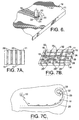
- Figures 4A-4B are cross-sectional views illustrating conventional I-beams being subjected to an alternating load, as is known in the art;
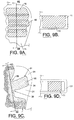
- Figure 5A is a cross-sectional view illustrating selective grain structure refinement of a structural member by mixing the entire thickness of the member, according to one embodiment of the present invention;
- Figure 5B is a cross-sectional view illustrating selective grain structure refinement of a structural member by mixing a portion of the thickness of the member, according to another embodiment of the present invention;
- Figure 5C is a cross-sectional view illustrating selective grain structure refinement of a structural member by mixing the entire thickness of the member, according to still another embodiment of the present invention;
- Figure 6 is a perspective view illustrating selective grain structure refinement of a structural member, according to one embodiment of the present invention;
- Figure 7A is a plan view illustrating one embodiment of a structural member according to the present invention having a plurality of reinforcing ribs;
- Figure 7B is a perspective view illustrating another embodiment of a structural member according to the present invention having a plurality of containment zones;
- Figure 7C is a plan view illustrating another embodiment of a structural member according to the present invention having an open curvilinear containment zone;
- Figure 8 is a photograph illustrating the propagation of cracks along the periphery of a region of locally refined grain structure, according to one embodiment of the present invention;
- Figure 9A is a plan view illustrating one embodiment of a structural member according to the present invention having a continuous area of locally refined grain structure defined by a plurality of overlapping elongate regions of locally refined grain structure;
- Figure 9B is a cross-sectional view along
lines 9B-9B of Figure 9A of the structural member of Figure 9A; - Figure 9C is a plan view illustrating the finish machined profile of the structural member of Figure 9A;
- Figure 9D is a cross-sectional view along
lines 9D-9D of Figure 9C of the structural member of Figure 9C; - Figure 10 is a cross-sectional view illustrating one embodiment of a structural member according to the present invention having a threaded opening machined therein;
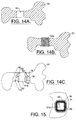
- Figure 11 is a plan view illustrating one embodiment of a structural member according to the present invention having a window;
- Figure 12 is a perspective view illustrating one embodiment of a tubular structural member according to the present invention having spirally configured regions of locally refined grain structure;
- Figure 13A is a perspective view illustrating one embodiment of a cast structural member according to the present invention prior to being shaped into a finished configuration;
- Figure 13B is a perspective view illustrating the structural member of Figure 13A after being shaped into its finished configuration;
- Figure 14A is a cross-sectional view illustrating a cast structural member having a recess machined therein;
- Figure 14B is a cross-sectional view illustrating the structural member of Figure 14A having an insert positioned within the aperture;
- Figure 14C is a plan view illustrating the insert joined to the structural member of Figure 14B through a weld joint and a region of locally refined grain structure adjacent to the weld joint, according to one embodiment of the present invention;
- Figure 15 is a plan view illustrating an insert joined through a weld joint to a structural member and a region of locally refined grain structure adjacent to the weld joint, according to another embodiment of the present invention; and
- Figure 16 is a flow chart illustrating the operations performed, according to one embodiment of the present invention, in order to fabricate the structural assembly of Figure 1 and the structural members of Figures 2-15.
-
- The present invention now will be described more fully hereinafter with reference to the accompanying drawings, in which preferred embodiments of the invention are shown. This invention may, however, be embodied in many different forms and should not be construed as limited to the embodiments set forth herein; rather, these embodiments are provided so that this disclosure will be thorough and complete, and will fully convey the scope of the invention to those skilled in the art. Like numbers refer to like elements throughout.
- Referring to the drawings and, in particular, to Figure 1, there is illustrated a
structural assembly 10 according to the present invention. Thestructural assembly 10 can be used in the construction of a variety of structures, including the frame of an aircraft. Thestructural assembly 10 is constructed of a plurality ofstructural members 11 that are welded together or secured usingsuitable fasteners 12. Thestructural assembly 10 illustrated in Figure 1 includes two I-beams 14 and oneplanar member 15. However, other types of structural assemblies can be constructed, if so desired. Although a variety of materials can be utilized, thestructural members 11 are preferably formed from steel, stainless steel, magnesium, magnesium-based alloys generally, brass, copper, beryllium, beryllium-copper alloys, aluminum, aluminum-based alloys generally, aluminum-zinc alloys, aluminum-copper alloys, aluminum-lithium alloys, or titanium. Thestructural members 11 can be machined from stock material or cast. As illustrated in Figure 2A-2D, thestructural members 11 can be cast or machined in a variety of configurations, as is known in the art, based upon the load requirements and other design parameters of thestructural assembly 10. - As discussed above, during use,
structural assemblies 10 are subjected to static and cyclic loads, as well as a variety of environmental conditions, temperature variations, and severe acoustic and vibration environments, all of which create mechanical and thermal stresses, which are collectively referred to herein as "operational stresses". While the entirestructural member 11 is generally subjected to varying magnitudes of operational stress, certain regions of each structural member are typically subjected to comparatively higher magnitudes of operational stress. For example, referring to Figures 4A and 4B , there is illustrated an I-beam 24 having opposedend portions 25a, b and aweb 27 interconnecting the end portions. One of theend portions 25a of the I-beam 24 is secured to a fixedsupport structure 29 while theother end portion 25b is subjected to cyclic loading, such as an alternatingload 13 indirections 13a, b perpendicular to the plane of theweb 27, as illustrated in Figure 4A, or an alternatingbending load 13c, as illustrated in Figure 4B. The cyclic loading creates moment loads where theweb 27 interconnects with theend portions 25a, b. The moment loads result in bending and shear forces, which, when combined with the notch effect of the sharpmachined radii 28 at the interconnection of the web and the end portions, generally results in segments of theend portions 25a, b and theweb 27 adjacent where the web interconnects with the end portions being subjected to comparatively higher magnitudes of operational stress. In another embodiment (not shown), the loads applied to an I-beam can be such that regions of comparatively high operational stress are located along the length of theweb 27. Regions of comparatively high operational stresses can be identified from known mathematical equations and computational techniques, such as finite element analysis. - As illustrated in Figure 1, at least one
structural member 11 of thestructural assembly 10 defines one ormore regions 16 having a locally refined grain structure, whichregions 16 at least partially encompass a region of comparatively high operational stress. Preferably, the grain size within the locally refinedregions 16 ranges in order of magnitude from approximately .0001 to .0002 inches (approximately 3 to 5 microns) and the grains have an equiaxed shape throughout the locally refined region. In contrast, while the grain structure ofstructural members 11 formed by casting varies in size, shape and orientation depending upon the composition of the cast alloy and the method of cooling the structural member after being cast, typically, the grain size of cast structural members ranges in order of magnitude from approximately .1 to .01 inches (approximately 2.5 to .25 mm). Since the edges of a cast structural member cool more quickly than the interior portions of the member, the grains of a cast structural member usually have a columnar shape at the edges of the member, transitioning to a cubic shape towards the interior of the member. - As illustrated in Figure 6, the
regions 16 of locally refined grain structure are formed by mixing or stirring a portion of thestructural member 11 with a non-consumable rotating frictionstir welding probe 18. To effect mixing, thestructural member 11 is first secured to a worktable of a friction stir welding machine by means of a conventional clamp (not shown). The rotating frictionstir welding probe 18 is then inserted through theouter surface 19 of thestructural member 11 to a pre-selected depth. An opening can be predrilled or tapped through the outer surface of thestructural member 11 to receive the rotating probe, but preferably the rotating probe is thrust directly into and through theouter surface 19 of thestructural member 11. Once inserted into the structural member, the rotatingprobe 18 imparts mixing under theshoulder 20 of the probe by shearing action parallel to theouter surface 19 of the structural member. The rotatingprobe 18 also imparts mixing around the threadedportion 22 of the probe parallel to theprobe axis 23. See U.S. Patent No. 5,460,317 to Thomas et al. for a general discussion of friction stir welding, the entire contents of which are incorporated herein by reference. - The depth the
rotating probe 18 is inserted into thestructural member 11 depends upon the material properties and dimensions of the structural member, as well as the types of loads that will be supported by, and the magnitude of operational stress that will be applied to, the structural member. Cyclic or alternating loads can result in micro-cracks initiating on the surface of a structural member in the regions of comparatively high operational stress, which cracks can eventually result in fatigue failure of the structural member. In one embodiment, only a portion of the thickness of thestructural member 11, such as thewebs 17 of the I-beams 14 illustrated in Figure 1 and the surfaces of thestructural members 11 illustrated in Figures 2A-2D, is selectively mixed to formregions 16 of locally refined grain structure (referred to herein as "partial-penetration mixing"). For example, to partial-penetration mix a structural member having a thickness of 1 inch, the rotating probe can be inserted through theouter surface 19 of the structural member to a depth of approximately .25 inches. Advantageously, theregions 16 of locally refined grain structure resist the formation and propagation of micro-cracks thereby selectively improving the strength, toughness and fatigue resistance of thestructural member 11 in the corresponding regions of comparatively high operational stress. - In another embodiment, as illustrated in Figure 5B, the probe is thrust to a depth D where the
tip 18a of the rotating probe is a distance d from theopposite side 19a of thestructural member 11. During mixing, the rotatingprobe 18 exerts approximately 1000 to 10,000 pound-force or more on thestructural member 11, depending on the size of the probe and the depth of probe penetration, and generates sufficient frictional heat to raise the temperature of the portions of the structural member adjacent the rotating probe to between approximately 700 °F and a temperature just below the solidus of the alloy forming the structural member. The frictional heat generated by the rotatingprobe 18 in combination with the force exerted by the probe on the structural member can result in a forging-like effect on theunmixed portion 21 of the structural member between theprobe tip 18a and theopposite side 19a of the structural member that locally refines the grain structure of the unmixed portion without the probe breaching theopposite side 19a. Preferably, to refine the grain structure of theunmixed portion 21 of thestructural member 11 between theprobe tip 18a and theopposite side 19a of the structural member, theprobe 18 is thrust into the structural member to a depth D such that the probe tip is a distance d of approximately .007 inches from the opposite side of the structural member. - According to another embodiment of the present invention, as illustrated in Figures 5A and 5C, the entire thickness of the
structural member 11 can be mixed to define aregion 16 of locally refined grain structure (referred to herein as "full-penetration mixing"). Full-penetration mixing is preferred for relatively thin structural members, such as structural members with thickness less than approximately .25 inches, but can also be employed to formregions 16 of locally refined grain structure in structural members with thickness greater than .25 inches. As illustrated in Figure 5A, to full-penetration mix astructural member 11 with thickness less than approximately 1.5 inches, the rotatingprobe 18 can be inserted into theouter surface 19 of the structural member and thrust through the entire thickness of the structural member such that the probe breaches theopposite side 19a of the structural member. After forming theregion 16 of locally refined grain structure in the structural member, bothsides - When forming
elongate regions 16 of locally refined grain structure, as discussed below, the rate of travel of theprobe 18 through the structural member is dependent, in part, upon the thickness of thestructural member 11. Typically, the rate of travel of the rotating probe through the structural member is proportional to the thickness of the member and ranges from approximately 5 to 30 inches per minute. For structural members with thickness greater than approximately 1.5 inches and, particularly, for structural members with thickness greater than approximately 3 inches full-penetration mixing of the structural member is preferably effected by partial-penetration mixing the structural member from bothsides rotating probe 18 into and through a firstouter side 19 of thestructural member 11 to a depth a equal to a pre-selected portion of the thickness of the structural member to form afirst region 36 of locally refined grain structure. Arotating probe 18 can then be inserted into and through theopposite side 19a of thestructural member 11 opposite to the first locally refinedregion 36 to a depth β to form asecond region 36a of locally refined grain structure. In one embodiment, the depth β is approximately equal to the thickness of thestructural member 11 less the insertion depth a of the probe in the firstouter side 19 of the structural member. In another embodiment, the depth β is greater than the thickness of thestructural member 11 less the insertion depth a of the probe in the firstouter side 19 such that thesecond region 36a of locally refined grain structure at least partially overlaps thefirst region 36 of locally refined grain structure. - For
structural members 11 having elongate regions of comparatively high operational stress, the rotating frictionstir welding probe 18 can be moved through thestructural member 11 along a path corresponding to the region of high operational stress, as illustrated by thearrow 30 in Figure 6, to create anelongate region 16 of locally refined grain structure. According to one embodiment, as illustrated in Figure 7A, forstructural members 11 having continuous surface areas that are subjected to comparatively high operational stresses, a plurality of reinforcing "ribs" 26, which areelongate regions 16 of refined grain structure, can be formed in the structural member using a rotating frictionstir welding probe 18. - As previously discussed and, as illustrated by the photograph of Figure 8, the
regions 16 of locally refined grain structure resist the formation and propagation of micro-cracks in the surface of the structural member such that thecracks 33 generally do not intersect or traverse the locally refined regions, but rather propagate along the periphery of the regions. In one embodiment, as illustrated in Figure 7B, reinforcingribs 26 can be formed about the surface of thestructural member 11 so as to intersect other ribs to thereby define bounded regions orcontainment zones 32. Advantageously, the intersectingribs 26 restrict the propagation ofmicro-cracks 33 formed in the surface of the structural member to the area defined by the corresponding containment zone, thus, significantly improving the fatigue resistance of the structural member in the region of comparatively high operational stress. Forstructural members 11 with thickness of approximately .5 inches or less, preferably the reinforcingribs 26 defining thecontainment zones 32 are formed by full-penetration mixing. For relatively thick structural members, the reinforcingribs 26 defining thecontainment zones 32 can be formed by partial-penetration mixing. While thecontainment zones 32 illustrated in Figure 7B have rectangular configurations and are closed or completely bounded by reinforcingribs 26, the containment zones according to the present invention can also be at least partially open or unbounded and can have other configurations, including both linear and curvilinear configurations. For example, as illustrated in Figure 7C, anelongate region 16 of locally refined grain structure can be formed having acurvilinear portion 39, such as a diminishing spiral, that confines and redirects a propagating crack onto itself to blunt the crack and prevent further propagation. - According to another embodiment of the present invention, as illustrated in Figures 9A and 9B, for
structural members 11 having continuous surface areas that are subjected to comparatively high operational stresses, overlappingregions 16 of locally refined grain structure can be formed to define acontinuous area 46 of locally refined grain structure. As illustrated in Figures 9C and 9D, thestructural member 11 can then be machined to remove anyexcess material 31 to provide a structural member having the desired dimensions and configuration. Advantageously, where thestructural member 11 includes a flange orother protuberance 34 that will be subjected to comparatively high operational stress, such as the one illustrated in Figure 9C, acontinuous area 46 of locally refined grain structure can be machined to provide aprotuberance 34 having selectively improved strength, toughness and fatigue resistance. - In another embodiment, the
outer surface 19 of thestructural member 11 defines a notch, groove, aperture orother surface discontinuity 35, which concentrates stress resulting in comparatively high operational stress proximate to the discontinuity. For example, as illustrated in Figure 9C, thestructural member 11 can include a sharpmachined radii 38 where aprotuberance 34 interconnects with the member; as illustrated in Figure 10, the structural member can include a threadedopening 37 to facilitate securing the member to other structural members to form astructural assembly 10; or, as illustrated in Figure 11, the structural member can include an aperture that defines a window or opening 40 in an aerospace vehicle. Prior to machining or forming a threadedopening 37 or otherstress raising discontinuity 35, an area of thestructural member 11 that at least partially encompasses the discontinuity can be mixed with a rotating frictionstir welding probe 18 to form aregion 16 of locally refined grain structure. The threadedopening 37 orother discontinuity 35 can then be machined into theouter surface 19 of thestructural member 11 such that thediscontinuity 35 is at least partially contained within theregion 16 of locally refined grain structure. As illustrated in Figure 10, theregion 16 of locally refined grain structure preferably encompasses and surrounds the threaded opening and extends away from the centerline of the opening a distance ranging from approximately the diameter of the threaded opening to twice the opening diameter. The enhanced material properties of themixed region 16 will compensate for the increased operational stress in the immediate vicinity of thediscontinuity 35. - In one embodiment, a threaded
opening 37 is formed by mixing the area of thestructural member 11 that encompasses thediscontinuity 35 with a rotating frictionstir welding probe 18 to form aregion 16 of locally refined grain structure. The rotatingprobe 18, which preferably has threads with dimensions corresponding to the threads of the threadedopening 37, is moved through thestructural member 11 to the location on theouter surface 19 of the structural member where the threaded opening is to be formed and is inserted into the member to a depth corresponding to the desired depth of the threaded opening. Once the rotatingprobe 18 is in the desired location and depth, rotation of the probe is discontinued. The newly formedregion 16 of locally refined grain structure is then allowed to cool and, thereafter, theprobe 18 is withdrawn from thestructural member 11 by unthreading the probe from the structural member to thereby define the threadedopening 37. Advantageously, the threads of the threadedopening 37 are encompassed by theregion 16 of locally refined grain structure so that the threads will have enhanced material properties to compensate for increased operational stress. - In another embodiment, as illustrated in Figures 3A and 3B, the
end portions 55a, b of a cast I-beam 57 can be mixed with a rotating frictionstir welding probe 18 prior to final machining to formelongate regions 16 of locally refined grain structure to compensate for the increased operational stress in the immediate vicinity of the sharpmachined radii 58 adjacent where the web interconnects with the end portions. Theelongate regions 16 of locally refined grain structure preferably overlap to define acontinuous area 46 of locally refined grain structure that extends through theend portions 55a, b of the I-beam and at least partially into the corresponding ends of theweb 54. After forming theelongate regions 16 of locally refined grain structure, the I-beam 57 can be machined to removeexcess material 53 to provide astructural member 11 having the desired dimensions and configuration. - In another embodiment, as illustrated in Figure 13, a window or opening 40 in a structural assembly (not shown), such as an aerospace vehicle, is formed by casting a
structural member 11 in a pre-selected configuration having the desired opening, as is known in the art. Prior to final machining, thestructural member 11 is mixed with a rotating frictionstir welding probe 18 about at least a portion of the circumference of thewindow 40 to form a region orregions 16 of locally refined grain structure that have enhanced material properties to compensate for increased operational stress in the immediate vicinity of thediscontinuity 35. While the locally refined region orregions 16 can be formed by partial-penetration mixing, preferably, thestructural member 11 is full-penetration mixed about the circumference of thewindow 40 to form a plurality of overlappingelongate regions 16 of locally refined grain structure. Overlappingregions 16 of locally refined grain structure can also be formed on either end of thestructural member 11 to definecontinuous areas 46 of locally refined grain structure that at least partially encompass a plurality of threadedopenings 37 for securing the structural member to other structural members to form the structural assembly. After forming the region orregions 16 of locally refined grain structure, thestructural member 11 can be machined to removeexcess material 53 to provide a structural member having the desired dimensions and configuration. - Referring to Figure 12, there is illustrated a cast tubular
structural member 11, according to one embodiment of the present invention, that will be subjected to atorque load 42. The torque load will result in thestructural member 11 being subjected to comparatively higher magnitudes of operational shear stress such that the expected failure mode is a 45° helically shaped shear failure zone. To compensate for increased operational stress, the structural member is preferably mixed with a rotating frictionstir welding probe 18 to define one or moreelongate regions 16 of locally refined grain structure having a spiral configuration. Advantageously, while theunmixed portions 43 of the caststructural member 11 are relatively brittle, the locally refinedregions 16 are relatively ductile and, thus, provide zones for yielding thereby improving the strength, toughness and fatigue resistance of thestructural member 11 in the corresponding regions of comparatively high operational stress. - In another embodiment, as illustrated in Figures 13A and 13B, a cast
structural member 11 is subjected to machining during fabrication, such as stretching a portion of the structural member to shape the member into a desired configuration. Prior to performing the machining operation, an area of thestructural member 11 that at least partially encompasses the area that will be machined can be mixed with a rotating frictionstir welding probe 18 to form aregion 16 of locally refined grain structure that has improved ductility and formability relative to the unmixed portions of the cast structural member. The structural member can then be machined into the desired configuration, as is known in the art. Advantageously, as illustrated in Figure 13B, when the machining operation is performed, the stretching will occur in the locally refinedregion 16 such that any details cast into theunmixed portions 43 of thestructural member 11 adjacent the locally refined region will remain dimensionally stable throughout the machining operation. - According to another embodiment of the present invention, the structural member can include one or more inserts joined to the member through a weld joint formed by either a fusion or non-fusion welding process. For example, as illustrated in Figures 14A-14C, the
structural member 51 includes aninsert 51a joined to the member through a friction stir weld joint 52. Referring to Figure 14A, thestructural member 51 can include a milled recess oraperture 50 having dimensions corresponding to the dimensions of theinsert 51a such that the insert can be slip or press fit to the structural member prior to welding. While theinsert 51a can comprise the same material as thestructural member 51, preferably, the insert comprises a different material. Similarly, the insert and structural member can be formed from the same or a different fabrication process, such as casting or as a wrought or machined component. In another embodiment, as illustrated in Figure 15, theinsert 51b can comprise a lining for anaperture 56 defined by thestructural member 51 and wherein the insert is joined to the structural member by a fusion weld joint 52. The transition in grain size and structure between theinsert 51b and thestructural member 51 at the weld joint 52, particularly where the insert is formed of a different material or a different fabrication process, creates stress risers resulting in comparatively high operational stress. To compensate for increased operational stress due to grain size discontinuity, thestructural member 51 andinsert 51b are preferably mixed with a rotating frictionstir welding probe 18 adjacent to, and along the path of, the weld joint 52 to define one or moreelongate regions 16 of locally refined grain structure. - According to another embodiment (not shown), the structural member defines an external or internal defect that concentrates stress resulting in comparatively high operational stress proximate to the defect. For example, an external defect in a cast structural member may include, gas or blow holes communicating with the surface; inclusions, such as scale or oxides; or hot tears and cracks due to shrinkage after casting. Internal defects in castings may include internal shrinkage. An external defect in a forging may include laps, laminations, slivers, scabs, seams, bark, or cracks. To compensate for increased operational stress and heal the defect, the structural member is preferably mixed with a rotating friction stir welding probe to define one or more regions of locally refined grain structure.
- Once a
region 16 of locally refined grain structure having a desired shape and length is formed in thestructural member 11, the rotatingprobe 18 is withdrawn from the member. The withdrawal of therotating probe 18 can result in an irregularity in theouter surface 19 of thestructural member 11. In one embodiment (not shown), the portions of the structural member containing any irregularities caused by the withdrawal of therotating probe 18 can be cutaway or filled. Preferably, thestructural member 11 is then machined into a pre-selected shape and thickness, as required by the specific design loads and specifications of the resultingstructural assembly 10, or to obtain the desired surface finish. For example, a CNC milling machine can be used to machine thestructural member 11 as necessary. - The rotation of the friction
stir welding probe 18 within thestructural member 11 generates sufficient heat energy to plasticize the surrounding material thereby creating a severely deformed, but highly refined grain structure. In addition, the mixing process eliminates voids, thus, increasing the density of thestructural member 11 in themixed regions 16. Advantageously, theregions 16 of locally refined grain structure have significantly enhanced strength, toughness and fatigue resistance in comparison to the unmixed portions of thestructural member 11. Since theregions 16 of locally refined grain structure encompass all or at least a portion of the region that is anticipated to undergo comparatively high operational stress, theregions 16 of locally refined grain structure allow the resulting region to better withstand the high operational stress. Due to the enhanced material properties of themixed regions 16 of thestructural members 11, the thickness of the structural members in those areas having mixed regions may be reduced to thereby obtain a reduction in the overall weight of astructural assembly 10 constructed according to the present invention. - The
structural members 11 may also be precipitation hardened to improve the material properties of the unmixed portions of the members. This is particularly advantageous for aluminum alloys. Precipitation hardening of metal alloys is a process whereby the mechanical properties of the metal alloy are improved by the formation of uniformly dispersed particles or precipitates of one or more secondary phases within the original phase matrix. As is known in the art, precipitation hardening requires that the metal alloy undergo two heat treatment processes, the first process being a solution heat treatment and the second process being a precipitation heat treatment, both of which are conducted at predetermined temperature schedules. While precipitation hardening may be conducted either before or after locally refining the grain structure of thestructural members 11, preferably, the precipitation hardening process is conducted after forming theregions 16 of locally refined grain structure. When precipitation hardening a structural member after locally refining the grain structure of the member, theregions 16 of locally refined grain structure should be sufficiently heated during mixing so as not to create an excessive amount of residual stress between the locally refined regions and the unmixed portions of the structural member. - Referring now to Figure 16, there is illustrated the operations performed to manufacture a structural member according to one embodiment of the present invention. The first step includes casting the structural member in a pre-selected configuration. See
block 60. Regions of the structural member having comparatively high operational stress are identified, such as by mathematical analysis or based upon prior experience. Seeblock 61. The structural member may be precipitation hardened to initially improve the material properties of the entire member. Seeblock 62. - The structural member is then secured to prevent movement. See
block 63. A friction stir welding probe is positioned adjacent a region of the structural member having a comparatively high operational stress. Seeblock 64. A region of the structural member having a comparatively high operational stress is then mixed with a rotating friction stir welding probe to locally refine the grain structure of the structural member within the region of high operational stress to thereby improve the strength, toughness and fatigue resistance of the structural member in the region. Seeblock 65. The mixing step includes inserting a rotating friction stir welding probe through the outer surface of the structural member proximate to the region of high operational stress to locally refine the grain structure of the high stress region. Seeblock 66. The mixing step may also include moving the rotating friction stir welding probe through the structural member along a path corresponding to the region of high operational stress. Seeblock 67. In one preferred embodiment, the securing, positioning and mixing steps are repeated to form more than one region of locally refined grain structure within the structural member. In another preferred embodiment, the positioning and mixing steps are repeated to form the desired number of regions of locally refined grain structure within the structural member, for example, a plurality of reinforcing ribs that are spaced apart and generally parallel. In one embodiment, the friction stir welding probe is withdrawn from the outer surface of the structural member to thereby define a threaded opening at least partially within the region of the structural member having a locally refined grain structure after the inserting step. Seeblock 68. - The structural member is then machined to a corresponding pre-selected shape and thickness. See
block 69. A threaded opening can be machined at least partially within the portion of the structural member having a locally refined grain structure. Seeblock 70. The structural member can then be precipitation hardened. Seeblock 71. The structural member is then secured to other structural members to form the frame of an aircraft. Seeblock 72. - Thus, the present invention provides an improved structural assembly and associated method of manufacture in which the assembly is constructed from structural members having enhanced strength, toughness and fatigue resistance in those regions subjected to comparatively high operational stresses. The improved structural assembly will have an increased operational life and reliability, as well as require less stock material with a corresponding decrease in the overall weight of the assembly. In addition, the improved method of manufacture also allows for the employment of more castings, which are typically less expensive to fabricate than an equivalent wrought or machined component, in construction of structural assemblies for the aerospace industry.
- Many modifications and other embodiments of the invention will come to mind to one skilled in the art to which this invention pertains having the benefit of the teachings presented in the foregoing descriptions and the associated drawings. Therefore, it is to be understood that the invention is not to be limited to the specific embodiments disclosed and that modifications and other embodiments are intended to be included within the scope of the appended claims. Although specific terms are employed herein, they are used in a generic and descriptive sense only and not for purposes of limitation.
Claims (20)
- A structural member, comprising:a first region characterized by comparatively high operational stress; anda second region having a more refined grain structure than other portions of the structural member, said second region at least partially encompassing said first region to thereby selectively improve the strength, toughness and fatigue resistance of the structural member in said first region.
- A structural assembly, comprising:a plurality of structural members, said plurality of structural members being secured together to form the structural assembly; andwherein at least one of said plurality of structural members defines a first region characterized by comparatively high operational stress and a second region having a more refined grain structure than other portions of the structural member, said second region at least partially encompassing said first region to thereby selectively improve the strength, toughness and fatigue resistance of said at least one structural member in said first region.
- A structural assembly as defined in Claim 1 or 2 wherein said at least one structural member defines a threaded opening at least partially contained within said second region.
- A structural assembly as defined in Claim 1, 2 or 3 wherein said plurality of structural members are formed of materials selected from the group consisting of steel, stainless steel, magnesium, magnesium-based alloys, brass, copper, beryllium, beryllium-copper alloys, aluminum, aluminum-based alloys, aluminum-zinc alloys, aluminum-copper alloys, aluminum-lithium alloys, and titanium.
- A structural assembly as defined in any of Claims 1-4 wherein said at least one structural member has an I-shaped configuration having opposed end portions and a web interconnecting the end portions, and wherein said second region includes at least a portion of the web.
- A structural assembly as defined in any of Claims 1-5 wherein said second region includes at least a portion of at least one of said opposed end portions.
- A structural assembly as defined in Claim 9 wherein said at least one structural member has a tubular configuration.
- A structural assembly as defined in any of Claims 1-7 wherein said at least one structural member defines a plurality of regions having refined grain structures, said regions being spaced apart and generally parallel.
- A structural assembly as defined in any of Claims 1-8 wherein said at least one structural member defines a first set of regions having refined grain structures and a second set of regions having refined grain structures, said first set of regions being spaced apart and generally parallel, said second set of regions being spaced apart and generally parallel, and wherein said first set of regions intersects said second set of regions to thereby define a plurality of containment zones.
- A structural assembly as defined in any of Claims 1-9 wherein said plurality of structural members are secured together to form the frame of an aircraft.
- A method for selectively improving the strength, toughness and fatigue resistance of a structural member in a region of high operational stress, the method comprising:securing the structural member to prevent movement;identifying a region of the structural member having a comparatively high operational stress;positioning a friction stir welding probe adjacent the region of high operational stress; andthereafter, inserting a rotating friction stir welding probe through the outer surface of the structural member to locally refine the grain structure of the structural member within the region of high operational stress to thereby improve the strength, toughness and fatigue resistance of the structural member in the region.
- A method as defined in Claim 11, further comprising casting the structural member in a pre-selected configuration prior to said securing step.
- A method as defined in Claim 11 or 12, further comprising moving the rotating friction stir welding probe through the structural member along a path corresponding to the region of high operational stress after said inserting step.
- A method as defined in Claim 11, 12 or 13, further comprising withdrawing the friction stir welding probe from the outer surface of the structural member to thereby define a threaded opening at least partially within the region of the structural member having a locally refined grain structure after said inserting step.
- A method for selectively improving the strength, toughness and fatigue resistance of a structural member in a region of high operational stress, the method comprising:securing a structural member to prevent movement;identifying a region of the structural member having a comparatively high operational stress;thereafter, mixing the region of the structural member having a comparatively high operational stress with a rotating friction stir welding probe to locally refine the grain structure of the structural member within the region of high operational stress to thereby improve the strength, toughness and fatigue resistance of the structural member in the region.
- A method as defined in Claim 15, wherein said mixing step comprises:inserting a rotating friction stir welding probe through the outer surface of the structural member to locally refine the grain structure of the structural member within the region of high operational stress; andthereafter, moving the rotating friction stir welding probe through the structural member along a path corresponding to the region of high operational stress.
- A method as defined in Claim 16, further comprising machining the structural member to a corresponding pre-selected shape and thickness after said inserting or mixing step.
- A method as defined in Claim 15, 16 or 17, further comprising machining a threaded opening at least partially within the region of the structural member having a locally refined grain structure after said inserting or mixing step.
- A method as defined in any of Claims 15-18, further comprising the step of precipitation hardening the structural member prior to inserting or said mixing step.
- A method as defined in any of Claims 15-19, further comprising the step of attaching the structural member to other structural members to form the frame of an aircraft.
Priority Applications (1)
| Application Number | Priority Date | Filing Date | Title |
|---|---|---|---|
| EP10168673.1A EP2261386B1 (en) | 2000-06-07 | 2001-05-30 | Grain refinement of structural members |
Applications Claiming Priority (2)
| Application Number | Priority Date | Filing Date | Title |
|---|---|---|---|
| US589504 | 2000-06-07 | ||
| US09/589,504 US6398883B1 (en) | 2000-06-07 | 2000-06-07 | Friction stir grain refinement of structural members |
Related Child Applications (2)
| Application Number | Title | Priority Date | Filing Date |
|---|---|---|---|
| EP10168673.1A Division EP2261386B1 (en) | 2000-06-07 | 2001-05-30 | Grain refinement of structural members |
| EP10168673.1A Division-Into EP2261386B1 (en) | 2000-06-07 | 2001-05-30 | Grain refinement of structural members |
Publications (3)
| Publication Number | Publication Date |
|---|---|
| EP1162283A2 true EP1162283A2 (en) | 2001-12-12 |
| EP1162283A3 EP1162283A3 (en) | 2003-11-12 |
| EP1162283B1 EP1162283B1 (en) | 2018-12-05 |
Family
ID=24358285
Family Applications (2)
| Application Number | Title | Priority Date | Filing Date |
|---|---|---|---|
| EP10168673.1A Expired - Lifetime EP2261386B1 (en) | 2000-06-07 | 2001-05-30 | Grain refinement of structural members |
| EP01202071.5A Expired - Lifetime EP1162283B1 (en) | 2000-06-07 | 2001-05-30 | Friction stir grain refinement method for structural members |
Family Applications Before (1)
| Application Number | Title | Priority Date | Filing Date |
|---|---|---|---|
| EP10168673.1A Expired - Lifetime EP2261386B1 (en) | 2000-06-07 | 2001-05-30 | Grain refinement of structural members |
Country Status (5)
| Country | Link |
|---|---|
| US (2) | US6398883B1 (en) |
| EP (2) | EP2261386B1 (en) |
| JP (1) | JP4233774B2 (en) |
| KR (1) | KR100535904B1 (en) |
| CA (1) | CA2348113C (en) |
Cited By (10)
| Publication number | Priority date | Publication date | Assignee | Title |
|---|---|---|---|---|
| EP1321199A2 (en) * | 2001-12-18 | 2003-06-25 | The Boeing Company | Method for preparing ultra-fine grain titanium and titanium-alloy articles and articles prepared thereby |
| WO2003097889A1 (en) * | 2002-05-14 | 2003-11-27 | The Boeing Company | Method of manufacturing rivets having high strength and formability |
| WO2004039527A2 (en) * | 2002-11-01 | 2004-05-13 | Airbus Uk Limited | Welding method |
| WO2006119732A1 (en) * | 2005-05-09 | 2006-11-16 | Airbus Deutschland Gmbh | Metal, integral structural component having improved residual strength |
| FR2903961A1 (en) * | 2006-07-21 | 2008-01-25 | Eurocopter France | Structural element for airframe of rotocraft e.g. helicopter, has insert mounted in cavities of lower cross-member without clearance, where insert has deformation crack and rupture, which are distributed on substantial portion of insert |
| US7523850B2 (en) | 2003-04-07 | 2009-04-28 | Luxfer Group Limited | Method of forming and blank therefor |
| EP2404682A1 (en) * | 2010-07-09 | 2012-01-11 | Southwire Company | A method for providing plastic zone extrusion and a method for providing friction stir |
| CN103984858B (en) * | 2014-05-12 | 2017-02-22 | 中国人民解放军空军工程大学 | Method for determining fatigue safety life of airplane structure based on inspection and repairing frequency |
| US9616497B2 (en) | 2010-07-09 | 2017-04-11 | Southwire Company | Providing plastic zone extrusion |
| CN114151711A (en) * | 2021-11-26 | 2022-03-08 | 江苏万和铝业有限公司 | High-strength anti-fracture corrosion-resistant composite aluminum pipe and production process thereof |
Families Citing this family (44)
| Publication number | Priority date | Publication date | Assignee | Title |
|---|---|---|---|---|
| CN100441935C (en) * | 1996-03-19 | 2008-12-10 | 株式会社日立制作所 | Friction stir welding method and structure body formed |
| DE10031510A1 (en) * | 2000-06-28 | 2002-01-17 | Airbus Gmbh | Structural component for an aircraft |
| US6712916B2 (en) * | 2000-12-22 | 2004-03-30 | The Curators Of The University Of Missouri | Metal superplasticity enhancement and forming process |
| JP2002273579A (en) * | 2001-03-15 | 2002-09-25 | Hitachi Ltd | Method of joining iron-base material and structure for the same |
| WO2003000455A1 (en) * | 2001-06-21 | 2003-01-03 | Black & Decker Inc. | Method and apparatus for fastening steel framing with a spin weld pin |
| WO2003001073A2 (en) * | 2001-06-21 | 2003-01-03 | Black & Decker Inc. | Method and apparatus for fastening steel framing with nails |
| WO2003000466A2 (en) * | 2001-06-21 | 2003-01-03 | Black & Decker Inc. | Method and apparatus for fastening steel framing by crimping |
| US6780525B2 (en) * | 2001-12-26 | 2004-08-24 | The Boeing Company | High strength friction stir welding |
| US6655575B2 (en) | 2002-04-16 | 2003-12-02 | The Curators Of University Of Missouri | Superplastic forming of micro components |
| US6726085B2 (en) * | 2002-05-14 | 2004-04-27 | The Boeing Company | Method and apparatus for producing a refined grain structure |
| US6923362B2 (en) * | 2002-09-30 | 2005-08-02 | The Curators Of University Of Missouri | Integral channels in metal components and fabrication thereof |
| US7122761B2 (en) * | 2002-11-12 | 2006-10-17 | Siemens Power Generation, Inc. | Friction processing weld preparation |
| US7505885B2 (en) * | 2003-01-24 | 2009-03-17 | The Boeing Company | Method and interface elements for finite-element fracture analysis |
| US6802444B1 (en) | 2003-03-17 | 2004-10-12 | The United States Of America As Represented By The National Aeronautics And Space Administration | Heat treatment of friction stir welded 7X50 aluminum |
| US6933057B2 (en) * | 2003-07-17 | 2005-08-23 | The Boeing Company | Friction stir welded assembly and method of forming a friction stir welded assembly |
| US6955283B2 (en) * | 2003-09-08 | 2005-10-18 | The Boeing Company | Adaptable mandrel for spin forming |
| US20050070374A1 (en) * | 2003-09-29 | 2005-03-31 | Technology Licensing, Llc | Enhanced golf club performance via friction stir processing |
| KR100619615B1 (en) * | 2003-10-27 | 2006-09-01 | 더 보잉 컴파니 | System and Associated Friction Stir WeldingFSW Assembly, Controller and Method for Performing a Friction Stir Welding Operation |
| JP4695355B2 (en) * | 2004-07-15 | 2011-06-08 | 新日本製鐵株式会社 | Boom / arm member for construction machine with excellent weld fatigue strength and method for manufacturing the same |
| US7225969B2 (en) * | 2004-12-10 | 2007-06-05 | Gm Global Technology Operations, Inc. | Friction stir processing for surface properties |
| US8220697B2 (en) * | 2005-01-18 | 2012-07-17 | Siemens Energy, Inc. | Weldability of alloys with directionally-solidified grain structure |
| US20080041921A1 (en) * | 2005-09-26 | 2008-02-21 | Kevin Creehan | Friction stir fabrication |
| US8632850B2 (en) | 2005-09-26 | 2014-01-21 | Schultz-Creehan Holdings, Inc. | Friction fabrication tools |
| US9266191B2 (en) | 2013-12-18 | 2016-02-23 | Aeroprobe Corporation | Fabrication of monolithic stiffening ribs on metallic sheets |
| US9511445B2 (en) | 2014-12-17 | 2016-12-06 | Aeroprobe Corporation | Solid state joining using additive friction stir processing |
| US8397974B2 (en) | 2005-09-26 | 2013-03-19 | Aeroprobe Corporation | Self-reacting friction stir welding tool with the ability to add filler material |
| US9511446B2 (en) | 2014-12-17 | 2016-12-06 | Aeroprobe Corporation | In-situ interlocking of metals using additive friction stir processing |
| US8875976B2 (en) | 2005-09-26 | 2014-11-04 | Aeroprobe Corporation | System for continuous feeding of filler material for friction stir welding, processing and fabrication |
| FR2916417B1 (en) * | 2007-05-23 | 2009-07-24 | Airbus France Sas | STRUCTURAL AIRCRAFT ELEMENT LOCATED AT THE INTERFACE BETWEEN A WING AND FUSELAGE |
| CN101945724A (en) * | 2007-12-17 | 2011-01-12 | 埃克森美孚研究工程公司 | High-strength nickel alloy welding by strain hardening |
| DE102008012282A1 (en) * | 2008-03-03 | 2009-09-17 | Airbus Deutschland Gmbh | Hull structure for airplane |
| US20100322778A1 (en) * | 2009-06-19 | 2010-12-23 | Carroll Iii John T | Method and apparatus for improving turbocharger components |
| US8220693B2 (en) * | 2009-11-09 | 2012-07-17 | GM Global Technology Operations LLC | Modified surfaces using friction stir processing |
| US8123104B1 (en) | 2010-04-06 | 2012-02-28 | United Launch Alliance, Llc | Friction welding apparatus, system and method |
| US7866532B1 (en) | 2010-04-06 | 2011-01-11 | United Launch Alliance, Llc | Friction stir welding apparatus, system and method |
| US8141764B1 (en) | 2010-04-06 | 2012-03-27 | United Launch Alliance, Llc | Friction stir welding apparatus, system and method |
| DE102010050160A1 (en) * | 2010-10-30 | 2012-05-03 | Volkswagen Ag | Method for influencing crack configuration of overload crack in surface or profile component made from steel of motor car, involves introducing local structural changes in area of free surfaces of vehicle part based on crack configuration |
| JP5431426B2 (en) * | 2011-08-23 | 2014-03-05 | 株式会社日立製作所 | Ni-base alloy large member, Ni-base alloy welded structure using Ni-base alloy large member, and manufacturing method thereof |
| US20140255620A1 (en) * | 2013-03-06 | 2014-09-11 | Rolls-Royce Corporation | Sonic grain refinement of laser deposits |
| US20170197274A1 (en) * | 2014-07-10 | 2017-07-13 | Megastir Technologies Llc | Mechanical flow joining of high melting temperature materials |
| JP6836153B2 (en) * | 2017-01-26 | 2021-02-24 | アイシン精機株式会社 | Friction stir welding method |
| WO2019016824A1 (en) | 2017-07-19 | 2019-01-24 | Shiv Nadar University | A method for modifying surface grain structure of the material and apparatus thereof |
| AU2018359514C1 (en) | 2017-10-31 | 2021-05-27 | MELD Manufacturing Corporation | Solid-state additive manufacturing system and material compositions and structures |
| CN110653478A (en) * | 2019-10-25 | 2020-01-07 | 宁夏中色新材料有限公司 | Beryllium-copper alloy plate strip roll butt welding method |
Citations (3)
| Publication number | Priority date | Publication date | Assignee | Title |
|---|---|---|---|---|
| US2284824A (en) | 1938-05-26 | 1942-06-02 | Elastic Stop Nut Corp | Anchor nut and the manufacture thereof |
| JPH10183316A (en) | 1996-12-25 | 1998-07-14 | Showa Alum Corp | Surface modifying method for aluminum casting material |
| JPH1151103A (en) | 1997-07-30 | 1999-02-23 | Showa Alum Corp | Metallic structural member having impact absorption function |
Family Cites Families (21)
| Publication number | Priority date | Publication date | Assignee | Title |
|---|---|---|---|---|
| US4395296A (en) * | 1981-06-22 | 1983-07-26 | Bethlehem Steel Corporation | Thermal mechanical process for steel slabs and the product thereof |
| US4728374A (en) | 1984-05-07 | 1988-03-01 | Eaton Corporation | Solution heat treated engine poppet valves |
| US4816087A (en) * | 1985-10-31 | 1989-03-28 | Aluminum Company Of America | Process for producing duplex mode recrystallized high strength aluminum-lithium alloy products with high fracture toughness and method of making the same |
| US4693747A (en) * | 1985-11-18 | 1987-09-15 | Aluminum Company Of America | Alloy having improved fatigue crack growth resistance |
| GB8603832D0 (en) | 1986-02-17 | 1986-03-26 | Friction Technology Ltd | Forming hard edges on materials |
| US4883545A (en) * | 1988-09-01 | 1989-11-28 | Colorado School Of Mines | Process for making a metallic article with improved resistance to surface cracking during cold forming |
| US4874437A (en) | 1989-02-08 | 1989-10-17 | Kioritz Corporation | Method of adjusting hardness of metallic material |
| US5145530A (en) | 1989-05-18 | 1992-09-08 | Cassady William E | Method of surface hardening titanium and other metals |
| US5167728A (en) | 1991-04-24 | 1992-12-01 | Inco Alloys International, Inc. | Controlled grain size for ods iron-base alloys |
| GB9125978D0 (en) | 1991-12-06 | 1992-02-05 | Welding Inst | Hot shear butt welding |
| JPH0762610A (en) * | 1993-08-23 | 1995-03-07 | Yoshiyuki Ogushi | Reinforced girder structure |
| US5556565A (en) * | 1995-06-07 | 1996-09-17 | The Boeing Company | Method for composite welding using a hybrid metal webbed composite beam |
| US5611479A (en) | 1996-02-20 | 1997-03-18 | Rockwell International Corporation | Friction stir welding total penetration technique |
| KR200200669Y1 (en) * | 1997-12-31 | 2001-01-15 | 이중구 | Connecting Structures of Aircraft Parts |
| US6230957B1 (en) * | 1998-03-06 | 2001-05-15 | Lockheed Martin Corporation | Method of using friction stir welding to repair weld defects and to help avoid weld defects in intersecting welds |
| US6168067B1 (en) * | 1998-06-23 | 2001-01-02 | Mcdonnell Douglas Corporation | High strength friction stir welding |
| US6045028A (en) * | 1998-07-17 | 2000-04-04 | Mcdonnell Douglas Corporation | Integral corrosion protection of friction-welded joints |
| DE69915506T2 (en) * | 1998-10-30 | 2005-03-03 | Corus Aluminium Walzprodukte Gmbh | ALUMINUM COMPOSITE PANEL |
| US6302315B1 (en) * | 2000-05-01 | 2001-10-16 | General Tool Company | Friction stir welding machine and method |
| AU2002352844A1 (en) * | 2001-11-27 | 2003-06-10 | The United States Of America As Represented By The Administrator Of The National Aeronautics And Spa | Thermal stir welding process and apparatus |
| US6660110B1 (en) * | 2002-04-08 | 2003-12-09 | The United States Of America As Represented By The Administrator Of The National Aeronautics And Space Administration | Heat treatment devices and method of operation thereof to produce dual microstructure superalloy disks |
-
2000
- 2000-06-07 US US09/589,504 patent/US6398883B1/en not_active Expired - Lifetime
-
2001
- 2001-05-16 CA CA002348113A patent/CA2348113C/en not_active Expired - Lifetime
- 2001-05-30 EP EP10168673.1A patent/EP2261386B1/en not_active Expired - Lifetime
- 2001-05-30 EP EP01202071.5A patent/EP1162283B1/en not_active Expired - Lifetime
- 2001-06-05 KR KR10-2001-0031350A patent/KR100535904B1/en active IP Right Grant
- 2001-06-06 JP JP2001171098A patent/JP4233774B2/en not_active Expired - Lifetime
-
2002
- 2002-02-08 US US10/072,789 patent/US6994916B2/en not_active Expired - Lifetime
Patent Citations (3)
| Publication number | Priority date | Publication date | Assignee | Title |
|---|---|---|---|---|
| US2284824A (en) | 1938-05-26 | 1942-06-02 | Elastic Stop Nut Corp | Anchor nut and the manufacture thereof |
| JPH10183316A (en) | 1996-12-25 | 1998-07-14 | Showa Alum Corp | Surface modifying method for aluminum casting material |
| JPH1151103A (en) | 1997-07-30 | 1999-02-23 | Showa Alum Corp | Metallic structural member having impact absorption function |
Cited By (18)
| Publication number | Priority date | Publication date | Assignee | Title |
|---|---|---|---|---|
| US6638381B2 (en) * | 2001-12-18 | 2003-10-28 | The Boeing Company | Method for preparing ultra-fine grain titanium and titanium-alloy articles and articles prepared thereby |
| EP1321199A3 (en) * | 2001-12-18 | 2003-11-12 | The Boeing Company | Method for preparing ultra-fine grain titanium and titanium-alloy articles and articles prepared thereby |
| EP1321199A2 (en) * | 2001-12-18 | 2003-06-25 | The Boeing Company | Method for preparing ultra-fine grain titanium and titanium-alloy articles and articles prepared thereby |
| CN1295372C (en) * | 2002-05-14 | 2007-01-17 | 波音公司 | Method of manufacturing rivets having high strength and formability |
| WO2003097889A1 (en) * | 2002-05-14 | 2003-11-27 | The Boeing Company | Method of manufacturing rivets having high strength and formability |
| US7534079B2 (en) | 2002-05-14 | 2009-05-19 | The Boeing Company | Rivets having high strength and formability |
| US6843404B2 (en) | 2002-05-14 | 2005-01-18 | The Boeing Company | Method of manufacturing rivets having high strength and formability |
| US6854634B2 (en) | 2002-05-14 | 2005-02-15 | The Boeing Company | Method of manufacturing rivets having high strength and formability |
| WO2004039527A2 (en) * | 2002-11-01 | 2004-05-13 | Airbus Uk Limited | Welding method |
| WO2004039527A3 (en) * | 2002-11-01 | 2004-06-17 | Airbus Uk Ltd | Welding method |
| US7740162B2 (en) | 2002-11-01 | 2010-06-22 | Airbus UK, Limited | Welding method |
| US7523850B2 (en) | 2003-04-07 | 2009-04-28 | Luxfer Group Limited | Method of forming and blank therefor |
| WO2006119732A1 (en) * | 2005-05-09 | 2006-11-16 | Airbus Deutschland Gmbh | Metal, integral structural component having improved residual strength |
| FR2903961A1 (en) * | 2006-07-21 | 2008-01-25 | Eurocopter France | Structural element for airframe of rotocraft e.g. helicopter, has insert mounted in cavities of lower cross-member without clearance, where insert has deformation crack and rupture, which are distributed on substantial portion of insert |
| EP2404682A1 (en) * | 2010-07-09 | 2012-01-11 | Southwire Company | A method for providing plastic zone extrusion and a method for providing friction stir |
| US9616497B2 (en) | 2010-07-09 | 2017-04-11 | Southwire Company | Providing plastic zone extrusion |
| CN103984858B (en) * | 2014-05-12 | 2017-02-22 | 中国人民解放军空军工程大学 | Method for determining fatigue safety life of airplane structure based on inspection and repairing frequency |
| CN114151711A (en) * | 2021-11-26 | 2022-03-08 | 江苏万和铝业有限公司 | High-strength anti-fracture corrosion-resistant composite aluminum pipe and production process thereof |
Also Published As
| Publication number | Publication date |
|---|---|
| US20040055666A1 (en) | 2004-03-25 |
| US6994916B2 (en) | 2006-02-07 |
| CA2348113A1 (en) | 2001-12-07 |
| KR100535904B1 (en) | 2005-12-12 |
| JP4233774B2 (en) | 2009-03-04 |
| EP2261386B1 (en) | 2019-03-27 |
| CA2348113C (en) | 2009-08-11 |
| US6398883B1 (en) | 2002-06-04 |
| EP1162283A3 (en) | 2003-11-12 |
| EP1162283B1 (en) | 2018-12-05 |
| EP2261386A1 (en) | 2010-12-15 |
| JP2002104289A (en) | 2002-04-10 |
| KR20010110325A (en) | 2001-12-13 |
Similar Documents
| Publication | Publication Date | Title |
|---|---|---|
| EP1162283B1 (en) | Friction stir grain refinement method for structural members | |
| Liu et al. | Tensile properties and fracture locations of friction-stir-welded joints of 2017-T351 aluminum alloy | |
| Nandan et al. | Recent advances in friction-stir welding–process, weldment structure and properties | |
| Afzal et al. | A comparative study of fatigue behavior and life predictions of forged steel and PM connecting rods | |
| Bagheri et al. | Friction stir spot vibration welding: improving the microstructure and mechanical properties of Al5083 joint | |
| JP2005519770A (en) | Method for producing rivets having high strength and formability | |
| Singh et al. | Effect of process parameters on microstructure and mechanical properties in friction stir welding of aluminum alloy | |
| Imam et al. | Deformation characteristics and microstructural evolution in friction stir welding of thick 5083 aluminum alloy | |
| Beygi et al. | Design of friction stir welding for butt joining of aluminum to steel of dissimilar thickness: Heat treatment and fracture behavior | |
| Mehdi et al. | Influence of friction stir processing on the mechanical and microstructure characterization of single and double V-groove tungsten inert gas welded dissimilar aluminum joints | |
| Dorbane et al. | Effect of temperature on microstructure and fracture mechanisms in friction stir welded Al6061 joints | |
| Huang et al. | In situ rolling friction stir welding for joining AA2219 | |
| Peter Martin et al. | Evaluation of additive friction stir deposition for the repair of cast Al-1.4 Si-1.1 Cu-1.5 Mg-2.1 Zn | |
| MohammadiSefat et al. | Friction Stir Welding of 5052-H18 aluminum alloy: Modeling and process parameter optimization | |
| Raja et al. | Investigate the process parameter on the friction stir welding of dissimilar aluminium alloys | |
| Dracup et al. | Friction stir welding as a rivet replacement technology | |
| Kaushik et al. | Influence of hook geometry on failure mechanism of Al6061-galvanized steel dissimilar FSW lap joint | |
| Ma et al. | Combined strengthening mechanism of solid-state bonding and mechanical interlocking in friction self-piercing riveted AA7075-T6 aluminum alloy joints | |
| Majeed et al. | Al alloy tailor-welded blanks fabrication via friction stir welding: effect of shoulder size | |
| Aliakbari et al. | Effect of through-thickness friction stir processing parameters on weld repair and modification of fusion-welded AA6061 aluminum alloy | |
| Chen et al. | Experimental study of jumbo size reduced beam section connections using high-strength steel | |
| Maddela et al. | Study on defects repairing using Friction Stir technologies | |
| Pinheiro | Local reinforcement of magnesium components by friction processing. Determination of bonding mechanisms and assessment of joint properties | |
| Jordon et al. | Fatigue in friction stir welding | |
| Senthil et al. | Experimental investigation on joining process of aluminium alloy 6063-T6 pipes using hybrid friction stir welding |
Legal Events
| Date | Code | Title | Description |
|---|---|---|---|
| PUAI | Public reference made under article 153(3) epc to a published international application that has entered the european phase |
Free format text: ORIGINAL CODE: 0009012 |
|
| AK | Designated contracting states |
Kind code of ref document: A2 Designated state(s): AT BE CH CY DE DK ES FI FR GB GR IE IT LI LU MC NL PT SE TR |
|
| AX | Request for extension of the european patent |
Free format text: AL;LT;LV;MK;RO;SI |
|
| PUAL | Search report despatched |
Free format text: ORIGINAL CODE: 0009013 |
|
| AK | Designated contracting states |
Kind code of ref document: A3 Designated state(s): AT BE CH CY DE DK ES FI FR GB GR IE IT LI LU MC NL PT SE TR |
|
| AX | Request for extension of the european patent |
Extension state: AL LT LV MK RO SI |
|
| 17P | Request for examination filed |
Effective date: 20031209 |
|
| AKX | Designation fees paid |
Designated state(s): DE FR GB |
|
| 17Q | First examination report despatched |
Effective date: 20061113 |
|
| REG | Reference to a national code |
Ref country code: DE Ref legal event code: R079 Ref document number: 60151024 Country of ref document: DE Free format text: PREVIOUS MAIN CLASS: C22F0001040000 Ipc: B64C0001060000 |
|
| RIC1 | Information provided on ipc code assigned before grant |
Ipc: B64C 1/06 19680901AFI20180226BHEP Ipc: C22F 1/00 19680901ALI20180226BHEP Ipc: C21D 9/00 19680901ALI20180226BHEP Ipc: B64C 1/00 19680901ALI20180226BHEP Ipc: C21D 1/34 20000101ALI20180226BHEP Ipc: C22F 1/04 19680901ALI20180226BHEP Ipc: B23K 20/12 19800101ALI20180226BHEP |
|
| GRAP | Despatch of communication of intention to grant a patent |
Free format text: ORIGINAL CODE: EPIDOSNIGR1 |
|
| STAA | Information on the status of an ep patent application or granted ep patent |
Free format text: STATUS: GRANT OF PATENT IS INTENDED |
|
| INTG | Intention to grant announced |
Effective date: 20180508 |
|
| GRAS | Grant fee paid |
Free format text: ORIGINAL CODE: EPIDOSNIGR3 |
|
| GRAA | (expected) grant |
Free format text: ORIGINAL CODE: 0009210 |
|
| GRAA | (expected) grant |
Free format text: ORIGINAL CODE: 0009210 |
|
| STAA | Information on the status of an ep patent application or granted ep patent |
Free format text: STATUS: THE PATENT HAS BEEN GRANTED |
|
| AK | Designated contracting states |
Kind code of ref document: B1 Designated state(s): DE FR GB |
|
| REG | Reference to a national code |
Ref country code: GB Ref legal event code: FG4D |
|
| REG | Reference to a national code |
Ref country code: DE Ref legal event code: R096 Ref document number: 60151024 Country of ref document: DE |
|
| RIC2 | Information provided on ipc code assigned after grant |
Ipc: C21D 1/34 20060101ALI20180226BHEP Ipc: C22F 1/00 20060101ALI20180226BHEP Ipc: B64C 1/00 20060101ALI20180226BHEP Ipc: C21D 9/00 20060101ALI20180226BHEP Ipc: B23K 20/12 20060101ALI20180226BHEP Ipc: B64C 1/06 20060101AFI20180226BHEP Ipc: C22F 1/04 20060101ALI20180226BHEP |
|
| REG | Reference to a national code |
Ref country code: DE Ref legal event code: R097 Ref document number: 60151024 Country of ref document: DE |
|
| PLBE | No opposition filed within time limit |
Free format text: ORIGINAL CODE: 0009261 |
|
| STAA | Information on the status of an ep patent application or granted ep patent |
Free format text: STATUS: NO OPPOSITION FILED WITHIN TIME LIMIT |
|
| 26N | No opposition filed |
Effective date: 20190906 |
|
| PGFP | Annual fee paid to national office [announced via postgrant information from national office to epo] |
Ref country code: FR Payment date: 20200525 Year of fee payment: 20 Ref country code: DE Payment date: 20200528 Year of fee payment: 20 |
|
| PGFP | Annual fee paid to national office [announced via postgrant information from national office to epo] |
Ref country code: GB Payment date: 20200527 Year of fee payment: 20 |
|
| REG | Reference to a national code |
Ref country code: DE Ref legal event code: R071 Ref document number: 60151024 Country of ref document: DE |
|
| REG | Reference to a national code |
Ref country code: GB Ref legal event code: PE20 Expiry date: 20210529 |
|
| PG25 | Lapsed in a contracting state [announced via postgrant information from national office to epo] |
Ref country code: GB Free format text: LAPSE BECAUSE OF EXPIRATION OF PROTECTION Effective date: 20210529 |