EP1161987A2 - Device and method for making a device for the catalytic production of hydrogen from hydrocarbons - Google Patents
Device and method for making a device for the catalytic production of hydrogen from hydrocarbons Download PDFInfo
- Publication number
- EP1161987A2 EP1161987A2 EP01113877A EP01113877A EP1161987A2 EP 1161987 A2 EP1161987 A2 EP 1161987A2 EP 01113877 A EP01113877 A EP 01113877A EP 01113877 A EP01113877 A EP 01113877A EP 1161987 A2 EP1161987 A2 EP 1161987A2
- Authority
- EP
- European Patent Office
- Prior art keywords
- channels
- catalyst
- disks
- openings
- disc
- Prior art date
- Legal status (The legal status is an assumption and is not a legal conclusion. Google has not performed a legal analysis and makes no representation as to the accuracy of the status listed.)
- Withdrawn
Links
Images


Classifications
-
- B—PERFORMING OPERATIONS; TRANSPORTING
- B01—PHYSICAL OR CHEMICAL PROCESSES OR APPARATUS IN GENERAL
- B01J—CHEMICAL OR PHYSICAL PROCESSES, e.g. CATALYSIS OR COLLOID CHEMISTRY; THEIR RELEVANT APPARATUS
- B01J8/00—Chemical or physical processes in general, conducted in the presence of fluids and solid particles; Apparatus for such processes
- B01J8/02—Chemical or physical processes in general, conducted in the presence of fluids and solid particles; Apparatus for such processes with stationary particles, e.g. in fixed beds
- B01J8/0278—Feeding reactive fluids
-
- B—PERFORMING OPERATIONS; TRANSPORTING
- B01—PHYSICAL OR CHEMICAL PROCESSES OR APPARATUS IN GENERAL
- B01J—CHEMICAL OR PHYSICAL PROCESSES, e.g. CATALYSIS OR COLLOID CHEMISTRY; THEIR RELEVANT APPARATUS
- B01J19/00—Chemical, physical or physico-chemical processes in general; Their relevant apparatus
- B01J19/24—Stationary reactors without moving elements inside
- B01J19/248—Reactors comprising multiple separated flow channels
- B01J19/249—Plate-type reactors
-
- B—PERFORMING OPERATIONS; TRANSPORTING
- B01—PHYSICAL OR CHEMICAL PROCESSES OR APPARATUS IN GENERAL
- B01J—CHEMICAL OR PHYSICAL PROCESSES, e.g. CATALYSIS OR COLLOID CHEMISTRY; THEIR RELEVANT APPARATUS
- B01J8/00—Chemical or physical processes in general, conducted in the presence of fluids and solid particles; Apparatus for such processes
- B01J8/02—Chemical or physical processes in general, conducted in the presence of fluids and solid particles; Apparatus for such processes with stationary particles, e.g. in fixed beds
- B01J8/0207—Chemical or physical processes in general, conducted in the presence of fluids and solid particles; Apparatus for such processes with stationary particles, e.g. in fixed beds the fluid flow within the bed being predominantly horizontal
- B01J8/0221—Chemical or physical processes in general, conducted in the presence of fluids and solid particles; Apparatus for such processes with stationary particles, e.g. in fixed beds the fluid flow within the bed being predominantly horizontal in a cylindrical shaped bed
-
- C—CHEMISTRY; METALLURGY
- C01—INORGANIC CHEMISTRY
- C01B—NON-METALLIC ELEMENTS; COMPOUNDS THEREOF; METALLOIDS OR COMPOUNDS THEREOF NOT COVERED BY SUBCLASS C01C
- C01B3/00—Hydrogen; Gaseous mixtures containing hydrogen; Separation of hydrogen from mixtures containing it; Purification of hydrogen
- C01B3/02—Production of hydrogen or of gaseous mixtures containing a substantial proportion of hydrogen
- C01B3/32—Production of hydrogen or of gaseous mixtures containing a substantial proportion of hydrogen by reaction of gaseous or liquid organic compounds with gasifying agents, e.g. water, carbon dioxide, air
- C01B3/323—Catalytic reaction of gaseous or liquid organic compounds other than hydrocarbons with gasifying agents
-
- B—PERFORMING OPERATIONS; TRANSPORTING
- B01—PHYSICAL OR CHEMICAL PROCESSES OR APPARATUS IN GENERAL
- B01J—CHEMICAL OR PHYSICAL PROCESSES, e.g. CATALYSIS OR COLLOID CHEMISTRY; THEIR RELEVANT APPARATUS
- B01J2208/00—Processes carried out in the presence of solid particles; Reactors therefor
- B01J2208/00008—Controlling the process
- B01J2208/00017—Controlling the temperature
- B01J2208/00477—Controlling the temperature by thermal insulation means
- B01J2208/00495—Controlling the temperature by thermal insulation means using insulating materials or refractories
-
- B—PERFORMING OPERATIONS; TRANSPORTING
- B01—PHYSICAL OR CHEMICAL PROCESSES OR APPARATUS IN GENERAL
- B01J—CHEMICAL OR PHYSICAL PROCESSES, e.g. CATALYSIS OR COLLOID CHEMISTRY; THEIR RELEVANT APPARATUS
- B01J2208/00—Processes carried out in the presence of solid particles; Reactors therefor
- B01J2208/02—Processes carried out in the presence of solid particles; Reactors therefor with stationary particles
- B01J2208/021—Processes carried out in the presence of solid particles; Reactors therefor with stationary particles comprising a plurality of beds with flow of reactants in parallel
- B01J2208/022—Plate-type reactors filled with granular catalyst
-
- B—PERFORMING OPERATIONS; TRANSPORTING
- B01—PHYSICAL OR CHEMICAL PROCESSES OR APPARATUS IN GENERAL
- B01J—CHEMICAL OR PHYSICAL PROCESSES, e.g. CATALYSIS OR COLLOID CHEMISTRY; THEIR RELEVANT APPARATUS
- B01J2219/00—Chemical, physical or physico-chemical processes in general; Their relevant apparatus
- B01J2219/24—Stationary reactors without moving elements inside
- B01J2219/2401—Reactors comprising multiple separate flow channels
- B01J2219/245—Plate-type reactors
- B01J2219/2451—Geometry of the reactor
- B01J2219/2453—Plates arranged in parallel
-
- B—PERFORMING OPERATIONS; TRANSPORTING
- B01—PHYSICAL OR CHEMICAL PROCESSES OR APPARATUS IN GENERAL
- B01J—CHEMICAL OR PHYSICAL PROCESSES, e.g. CATALYSIS OR COLLOID CHEMISTRY; THEIR RELEVANT APPARATUS
- B01J2219/00—Chemical, physical or physico-chemical processes in general; Their relevant apparatus
- B01J2219/24—Stationary reactors without moving elements inside
- B01J2219/2401—Reactors comprising multiple separate flow channels
- B01J2219/245—Plate-type reactors
- B01J2219/2476—Construction materials
- B01J2219/2477—Construction materials of the catalysts
- B01J2219/2481—Catalysts in granular from between plates
-
- B—PERFORMING OPERATIONS; TRANSPORTING
- B01—PHYSICAL OR CHEMICAL PROCESSES OR APPARATUS IN GENERAL
- B01J—CHEMICAL OR PHYSICAL PROCESSES, e.g. CATALYSIS OR COLLOID CHEMISTRY; THEIR RELEVANT APPARATUS
- B01J2219/00—Chemical, physical or physico-chemical processes in general; Their relevant apparatus
- B01J2219/24—Stationary reactors without moving elements inside
- B01J2219/2401—Reactors comprising multiple separate flow channels
- B01J2219/245—Plate-type reactors
- B01J2219/2476—Construction materials
- B01J2219/2477—Construction materials of the catalysts
- B01J2219/2482—Catalytically active foils; Plates having catalytically activity on their own
-
- B—PERFORMING OPERATIONS; TRANSPORTING
- B01—PHYSICAL OR CHEMICAL PROCESSES OR APPARATUS IN GENERAL
- B01J—CHEMICAL OR PHYSICAL PROCESSES, e.g. CATALYSIS OR COLLOID CHEMISTRY; THEIR RELEVANT APPARATUS
- B01J2219/00—Chemical, physical or physico-chemical processes in general; Their relevant apparatus
- B01J2219/24—Stationary reactors without moving elements inside
- B01J2219/2401—Reactors comprising multiple separate flow channels
- B01J2219/245—Plate-type reactors
- B01J2219/2476—Construction materials
- B01J2219/2483—Construction materials of the plates
- B01J2219/2485—Metals or alloys
- B01J2219/2486—Steel
-
- B—PERFORMING OPERATIONS; TRANSPORTING
- B01—PHYSICAL OR CHEMICAL PROCESSES OR APPARATUS IN GENERAL
- B01J—CHEMICAL OR PHYSICAL PROCESSES, e.g. CATALYSIS OR COLLOID CHEMISTRY; THEIR RELEVANT APPARATUS
- B01J2219/00—Chemical, physical or physico-chemical processes in general; Their relevant apparatus
- B01J2219/24—Stationary reactors without moving elements inside
- B01J2219/2401—Reactors comprising multiple separate flow channels
- B01J2219/245—Plate-type reactors
- B01J2219/2491—Other constructional details
- B01J2219/2492—Assembling means
- B01J2219/2493—Means for assembling plates together, e.g. sealing means, screws, bolts
-
- Y—GENERAL TAGGING OF NEW TECHNOLOGICAL DEVELOPMENTS; GENERAL TAGGING OF CROSS-SECTIONAL TECHNOLOGIES SPANNING OVER SEVERAL SECTIONS OF THE IPC; TECHNICAL SUBJECTS COVERED BY FORMER USPC CROSS-REFERENCE ART COLLECTIONS [XRACs] AND DIGESTS
- Y10—TECHNICAL SUBJECTS COVERED BY FORMER USPC
- Y10T—TECHNICAL SUBJECTS COVERED BY FORMER US CLASSIFICATION
- Y10T428/00—Stock material or miscellaneous articles
- Y10T428/24—Structurally defined web or sheet [e.g., overall dimension, etc.]
- Y10T428/24149—Honeycomb-like
Definitions
- the present invention relates to a device and a Method of manufacturing a catalytic device Generation of hydrogen from hydrocarbons, one Catalyst with feeds and formed in the catalyst Distribution channels for starting materials and derivatives and collecting channels for products included.
- Hydrogen which is used, among other things, as fuel for fuel cells, is technically complex. Hydrogen is therefore often stored in a chemically bound state, for example in the form of hydrocarbons or alcohols, and reformed from these substances according to the respective needs.
- a starting material mixture comprising hydrocarbon and water is passed along a suitable catalyst while supplying heat. If, for example, methanol is used as the starting material, the starting materials are reacted on the catalyst in accordance with the reaction equation CH 3 OH + H 2 O ⁇ CO 2 + 3H 2 .
- hydrocarbons are added to the substrate and water vapor over an end face or a lateral surface of the substrate supplied, the cylindrical Passages in the substrate are sealed against entry of the educts are.
- the catalyst material in the pores of the porous Materials find the catalytic reforming of hydrogen instead of.
- the product gas, the carbon dioxide and hydrogen contains, is distributed in the porous substrate and due to the hydrogen-separating thin layer can only Hydrogen content enter the cylindrical passages.
- the hydrogen is then passed through the passages, which act as outlet channels serve, dissipated. Non-hydrogen fractions of educt and Product gas is discharged from the substrate via a discharge line.
- the catalyst is outside of the porous substrate as a honeycomb-shaped catalyst.
- the porous substrate Immediately on the flow exit side of the honeycomb-shaped The catalyst is the porous substrate with the cylindrical Bushings arranged, the substrate itself does not contain a catalyst.
- the end face of the porous Substrate is compared to the honeycomb-shaped catalyst sealed so that product gas emerging from the catalyst can only flow into the passageways.
- the passages as outlet channels for the product gas of the catalyst serve.
- the cylindrical passages form in the porous substrate only outlet channels for the separated Hydrogen or the hydrogen-containing product gas of the catalyst.
- a larger entry area for the feed gas is about the honeycomb structure of the catalyst provided.
- the device is made of catalyst disks Distribution channels for the reactants and catalyst disks with Collection channels for the products that alternate with each other are stacked. The distribution channels and collection channels the stacked catalyst disks are perpendicular to each other aligned so that the guide channels, distribution channels and collecting channels an orthogonal system form.
- Catalyst disks that feed, distribute, Enable collecting and discharging the educts or products, can by pressing and sintering further catalyst material on already sintered catalyst layers are formed as catalyst disks with complex structures.
- the invention is based on the object To provide a device for the production of catalytic hydrogen, which is straightforward and few different Includes components that are simple to structure and manufacture are to specify, as well as a simple manufacturing process.
- inlet channels for feeding and distributing and outlet channels for distributing and derivation only through inverse closed or open can be a highly symmetrical structure of the device according to the invention can be achieved, i.e. an easy to assemble and manufacture construction.
- a such construction can be done by including repetitive Structures advantageous due to a small number different members, according to the structure are arranged several times, can be realized.
- channels in the form of straight channels are straight through many manufacturing processes such as drilling, milling, pressing easy to manufacture and fluidic advantageous.
- the channels with the same structure vertical channels. Therefore the inlet channels extend substantially in the direction of gravity.
- the inlet channels can be advantageous from above with educts be loaded. This will ensure a good distribution of the Educts reached on the catalyst surface.
- the Starting phase can e.g. liquid methanol in the inlet duct of a platinum-containing catalyst and collect with air react and thus heat up the catalyst. With a warmed The catalyst then evaporates the liquid metered methanol in the inlet channel and is distributed evenly there.
- inlet and outlet channels taper in cross section from open end tapered towards the closed end. This will for the educts, especially when dosing by atomization of liquids, a larger impact area in the inlet duct created or a better distribution on the surface of the inlet channel.
- the Device essentially consisting of catalyst disks arranged next to one another built with the same surface structure, the majority of channels with the same structure and the inverse arranged open and closed channel ends as one-sided Open surface structure of the catalytic converter disc shaped are and by joining the inlet and outlet channels the catalyst disks between the top and bottom adjacent catalyst disks are formed.
- the device is advantageously made of the same components built up, namely the catalyst disks, the simple are to be produced and have a simple structure.
- the surface structure is the catalyst disc designed so that the majority of equally structured channels evenly is spaced apart and either an odd number inlet channels to be formed or an odd number to be formed Has outlet channels.
- This allows an alternating arrangement the inlet and outlet channels also in the direction of joining of the catalyst disks can be reached if for example, every second catalyst disc by 180 ° around the Vertical axis of the catalyst disc rotated in the invention Device is arranged. So there is no need for two Types of catalyst disks with staggered arrangement of Inlet and outlet channels.
- the device according to the invention is advantageous Way basically from just three different ones Assemblies assembled.
- the openings of the top and bottom Slice can be done by simple machining such as drilling or Punching or already during production e.g. when pressing the discs are formed.
- the middle section from perpendicular to the upper and lower disc arranged catalyst disks with surface structure constructed, with the channel sections open on both sides as surface structure of the catalyst disk open on one side are formed and by joining the catalyst disks between the top and bottom of adjacent catalyst disks are trained.
- the open channel sections can be easily Generate surface treatment of the catalyst disc or can be molded during production.
- the length of the channel sections open on both sides is given by the Height of the vertically arranged catalyst layers specified.
- the middle section made parallel to the top and bottom Disk arranged catalyst disks built, the Channel sections open on both sides in the form of congruent ones Bushings formed in the catalyst disks are.
- all three can Assemblies namely upper disk, lower disk and catalytic converter disks following the same procedure, e.g. Drilling or Milling openings or bushings. This reduces the manufacturing effort.
- the device comprises an upper and a lower disc Openings, side walls and tubes with one side closed End that at the openings of the upper and lower disc are attached, the plurality of identically structured channels through the tubes and the open and closed channel ends through the openings in the upper and lower disc as well the ends of the tubes closed on one side are formed and that of the upper disc, lower disc and side walls spanned space is filled with catalyst material.
- the device is essentially of a few different ones Components, namely disks, tubes and side walls, which are also simple in construction. there the disks, side walls and tubes do not have to be made of catalyst material exist, but can be made of different materials be made in terms of cost and manufacturing technology to be selected. Difficulties like the Processing of catalyst material or when connecting catalyst material can occur with other materials like this be avoided.
- the Openings in the disc are arranged so that when the The openings are at certain angles in the plane of the disc of the non-rotated disc with those of the rotated Do not cover disk and staggered arrangements of the Make openings.
- the openings are arranged accordingly, which are not symmetrical with respect to certain angles of rotation can, upper and lower disc with one disc type with a single arrangement of the openings on the Disc can be realized.
- the washers are facing each other arranged twisted, creating an offset arrangement the openings of the upper and lower disc is reached.
- the openings are for rectangular or square panes so arranged on the disc that the openings at angles of rotation are offset from each other by 180 ° or 90 ° or 180 °.
- the angle of rotation is not due to the outer shape of the disc, but only by an appropriate Arrangement of the openings specified.
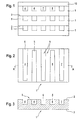
- Fig. 1 shows a top view of a first embodiment of the invention Device consisting of several catalyst disks 1, 10 is constructed.
- the catalyst disks 1, 10 are, for example, from catalyst powder by pressing produced to a shaped body and subsequent sintering.
- identical catalyst disks are used 1 with surface structure 9 joined together.
- a catalytic converter disc 10 without surface structure is the conclusion of last catalyst disk 1 provided.
- the catalyst disks 1, 10 are preferably connected to one another by press sintering.
- the surface structure 9 forms when joined together the catalyst disks 1, 10 between the top 2 and underside 3 of adjacent catalyst disks 1, 10 vertical Inlet and outlet channels 7, 8, which are parallel to each other are aligned.
- FIG. 2 shows a top view of a catalytic converter disk 1 of the type shown in FIG Fig. 1 shown device.
- the surface structure 9, the formed on an upper side 2 of the catalyst disk 1 can be done by exciting machining or by pressing the catalyst disc 1 are generated.
- the surface structure 9 comprises a plurality of channels 4 of the same structure, which interlocking and evenly arranged on the top 2 are distributed.
- Fig. 3 is to clarify the surface structure 9 shows a section through the catalyst disk 1 1 along the line A-A, the same Reference numerals designate the same elements.
- the equally structured channels 4 have an open and a closed end 6, 5. They are shaped so conically that the cross section from the open to the closed end rejuvenated.
- the channels 4 with open and closed at the top Channel ends form inlet channels 7 and channels 4 with channel ends open at the bottom and closed at the top Outlet channels 8.
- the inlet and outlet channels 7, 8 are alternating along the longitudinal direction of the catalyst disk 1 arranged.
- the number of inlet or outlet channels 7, 8 on a catalyst disk 1 is preferably odd.
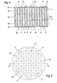
- Fig. 4 shows a section through a side view second embodiment of the device according to the invention.
- the device consists of an upper disc 21, a lower one Disc 22 and at least one central disc 23, all can have different strengths.
- the middle discs 23 consist of catalyst material and are, for example, from compressed and sintered catalyst powder manufactured.
- the upper disc 21 and lower disc 22 are preferably also made of catalyst material.
- the disks 21, 22, 23 can be connected by press sintering respectively.
- the middle disks 23 are parallel to the upper and lower Disk 21, 22 aligned.
- vertical bushings 24 are provided, which are evenly over the volume of the disk 23 are distributed.
- the implementations 24 of a plurality of middle disks 23 arranged one above the other are congruent with each other and form open on both sides Channel sections 25.
- the Channel sections open on both sides between the top and bottom of vertically arranged disks with corresponding Surface structure formed. These are on the top of the disc straight and parallel aligned recesses provided that spanned the full width of the disc extend.
- openings in the upper disk 21 and the lower disk 22 26 are arranged, which are not congruent with each other are. These can be done by drilling, punching or directly at Pressing the disks are generated.
- the openings 26 and Corresponding closed areas 27 limit the two sides open channel sections 25 of the middle disks 23. This become channels 4 with one-sided open and closed channel ends 6, 5 created, namely inlet and outlet channels 7, 8.
- the arrangement of the openings 25 is chosen so that inlet and alternate outlet channels 7, 8, i.e. on Inlet channel 7 is surrounded by several outlet channels 8 and vice versa.
- the arrangement of the openings 26 can also be designed such that the openings 26 when rotating the disc in the disc plane not congruent at least at a certain angle of rotation are mapped onto each other.
- One Arrangement of openings 26 can be for the upper and lower Disc 21, 22 a single type of disc can be used, wherein the function as an upper and lower disc 21, 22 through achieved correspondingly rotated installation of the washers becomes.
- FIG. 5 shows a top view of the second embodiment the device according to the invention.
- the one shown in Fig. 4 Section through the device according to the invention is along the Line A-A in Fig. 5 executed.
- the cross section of the device is circular in the present case, but as in the first embodiment also be angular.
- the openings 26 the upper disc 21 or the open channel ends 6 of the inlet channels 7 are visible from above, whereas the openings 26 of the lower disc 22 or the open channel ends 6 of the Outlet channels 8 are covered.
- Fig. 6 shows a section through a side view third embodiment of the device according to the invention.
- the device comprises an upper and a lower disk 21, 22, side walls 31 and tubes 30.
- the upper disc 21 and the lower washers 22 are spaced apart on the side walls 31 attached and together span a space 32.
- the tubes 30, which form the channels 4 with the same structure, are closed on one side.
- the tubes 30 are arranged inside the room 32 and so on the panes 21, 22 attached that the openings 26 with open ends 6th of the tubes 30 are aligned.
- the remaining interior is with catalyst material 33 filled in, e.g. by filling in a Catalyst powder.
- the disks 21, 22 and the tubes 30 are made made of porous material, the pore size being half so should be as small as the grain size of the catalyst material.
- the device according to the invention is double-walled Housing 34 attached.
- the space between the housing walls 34 is for thermal insulation with an insulating material 35, e.g. Expanded glass granules filled.
- Fastening means 36 are provided for connection.
- educts e.g. Methanol and water from above via a (not shown) Nozzle fed in fine spray. So that becomes a uniform distribution of the starting materials achieved.
- the educts are the powdered catalyst material or the disc pressed catalyst via the inlet channels 7 and Part also supplied via the upper disc 21.
- the reaction products In particular, hydrogen will be exhausts 8 collected and discharged.
- the flow of starting materials and products is in the Figg. 4 and 6 indicated by arrows.
- the device according to the invention is also particularly suitable as Cold start component, whereby by liquid dosing, gravity and good flowability positively influences the start time becomes.
- the embodiments of the device according to the invention can be used to build a multi-stage reactor.
- Suitable devices for producing an inventive 7 to 9, in turn same parts marked with identical reference numerals are.
- a hollow body 40 are in the axial direction spaced from each other an upper disc 21 and a lower one Disk 22 arranged, both disks 21, 22 each one Have a plurality of openings 26.
- the hollow body 40 can also be any other cross-sectional shapes, for example a square one Have cross-section.
- the would accordingly Disks 21, 22 have a square shape instead of a circular shape Have cross-sectional shape.
- molded bodies 41 are inserted with a positive fit, which are located in extend axially beyond the space 32.
- the remaining one Space between the two disks 21, 22 is filled with catalyst material 33 filled.
- the catalyst material pressed.
- both disks 21, 22 are movable relative to the hollow body 40, then on both discs 21, 22 act on a pressing force.
- the second Case has the advantage of more uniform pre-compression can be reached over the entire room 32. At the The discs 21, 22 can be pressed relative to the Move moldings 41.
- each channel 4 arise.
- inlet or Outlet channels 7, 8 must then still by suitable Measures in each case one channel end 5 in the area of the disks 21, 22 can be closed.
- each disc 21, 22 assigned a corresponding aperture are, the respective complementary openings 26 in the Close discs 21, 22.
- Simple tubular capillaries for example, can be used as shaped bodies 41 or steel round materials are used, which after the Pressing pulled out of the device in the axial direction become.
- the outer shape of this molded body 41 determines Here, the shape of the channels 4. It is therefore possible, in addition to the Circular shape also any other cross-sectional shapes for the To provide molded body 41, only the cross-sectional shape of the openings 26 to the cross-sectional shape of the molded bodies 41 must be coordinated. Furthermore, it is possible for molded articles 41 with different cross-sectional shape can be used. For example, a different shape in the edge area than in the central one Area. The cross-sectional shape of the molded body 41 can also be change in the axial direction.
- the shaped body at least in an axial Direction can be pulled through the openings 26.
- the shaped body for Position fixation have a stop (not shown), which, for example, when inserting on the space 32 facing away Side of one of the disks 21, 22 comes to rest.
- the molded bodies 41 can also be made of one material exist, which is suitable for the molded body 41 after the Melting melt.
- the material of the molded body 41 have a melting temperature at which the Catalyst material 33 is not damaged.
- a suitable diffusion layer can be applied, which when melting on the inner surfaces of the channels 4 remains and in the later operation of the device the diffusion rate the media from the channels 4 into the catalyst material 33 determined.
- the layer thickness can be advantageous here the diffusion layer over the axial extension of the Shaped body 41 vary.
- meltable moldings 41 also has the advantage that the possible Cross-sectional shapes of the molded body 41 less restricted is because the molded body 41 is not by the pressing corresponding openings 26 must be removed.
- the shaped bodies 41 can also have a shape opposite the shape of the openings 26 projecting cross-sectional shape. The size the openings 26 only have to be chosen so that the material the molded body 41 is still sufficient after pressing can be melted out.
- the disks 21, 22 themselves can also be made of catalyst material or from another material, for example steel, consist.
- the contact forces are preferably with a suitable one Stamp inserted on one or both sides.
- the hollow body 40 can be used as side wall 31, for example and thus part of the device for catalytic Form hydrogen production. Alternatively, the hollow body 40 but also be part of the manufacturing device, so that the catalyst body after pressing out of the hollow body 40 removed and later inserted into a suitable housing 34 becomes. If the hollow body 40 is used as the side wall 31, so this is preferably used to reduce weight finished device have the thinnest possible wall thickness. In this case, a thick-walled die 42 are provided during the pressing placed around the hollow body 40 and later removed can be. This die 42 preferably consists of two parts that are screwed together.
- a ring 42 may be provided for Filling the catalyst material 33 following the hollow body 40 .
- a device for hydrogen production can with a high proportion of catalyst based on the total mass the device, with reduced total volume and reduced Total mass can be produced.
- the manufacture easier because the number of individual parts required is relatively small and because there are fewer procedural steps requirement.
- a third embodiment according to FIG. 9 extend the shaped body 41 only in the axial direction a large part of the room 32. You will do this through openings 26 inserted in one of the two disks 21, 22 and however, do not extend completely to the opposite Disc 22, 21. Rather, the shaped bodies 41 are additional only by a suitable measure within the room 32 fixed in position, for example with the help of a arranged substantially centrally between the two disks 21, 22 Wire mesh 44 or the like.
- This method has the advantage that the respective closed end 5 of the channels 4 is formed directly by catalyst material, so that the discs 21, 22 only for the production, but not are required for the operation of the device and also on additional seals can be dispensed with.
Abstract
Description
Die vorliegende Erfindung betrifft eine Vorrichtung und ein Verfahren zur Herstellung einer Vorrichtung zur katalytischen Erzeugung von Wasserstoff aus Kohlenwasserstoffen, die einen Katalysator mit im Katalysator ausgebildeten Zuführungen und Verteilungskanälen für Edukte und Ableitungen und Sammelkanälen für Produkte umfaßt.The present invention relates to a device and a Method of manufacturing a catalytic device Generation of hydrogen from hydrocarbons, one Catalyst with feeds and formed in the catalyst Distribution channels for starting materials and derivatives and collecting channels for products included.
Die Speicherung von Wasserstoff, der unter anderem als Brennstoff für Brennstoffzellen eingesetzt wird, ist technisch aufwendig. Wasserstoff wird deshalb oft in chemisch gebundenem Zustand, z.B. in Form von Kohlenwasserstoffen oder Alkoholen gespeichert und aus diesen Stoffen entsprechend dem jeweiligen Bedarf reformiert. Zur Gewinnung von Wasserstoff aus Kohlenwasserstoffen wird ein Eduktgemisch, das Kohlenwasserstoff und Wasser umfaßt, unter Wärmezufuhr an einem geeigneten Katalysator entlanggeführt. Wird beispielsweise Methanol als Ausgangsstoff verwendet, so erfolgt die Umsetzung der Edukte am Katalysator gemäß der Reaktionsgleichung CH3OH + H2O → CO2 + 3H2.The storage of hydrogen, which is used, among other things, as fuel for fuel cells, is technically complex. Hydrogen is therefore often stored in a chemically bound state, for example in the form of hydrocarbons or alcohols, and reformed from these substances according to the respective needs. To obtain hydrogen from hydrocarbons, a starting material mixture comprising hydrocarbon and water is passed along a suitable catalyst while supplying heat. If, for example, methanol is used as the starting material, the starting materials are reacted on the catalyst in accordance with the reaction equation CH 3 OH + H 2 O → CO 2 + 3H 2 .
Aus der US-PS 5 674 301 ist eine Vorrichtung zum Reformieren von Wasserstoff bekannt, die ein poröses Substrat umfaßt, wobei in die Poren des porösen Substrates ein Katalysator für die katalytische Reformierung des Wasserstoffes eingelagert ist. Eine wasserstoffseparierende dünne Schicht ist auf inneren Oberflächen von zylindrischen Durchgängen vorgesehen, die in dem porösen Substrates ausgebildet sind. From US Pat. No. 5,674,301 is a device for reforming known from hydrogen, which comprises a porous substrate, wherein a catalyst for in the pores of the porous substrate the catalytic reforming of hydrogen is stored is. A hydrogen-separating thin layer is on the inside Surfaces provided by cylindrical passages are formed in the porous substrate.
Zur Erzeugung des Wasserstoffes werden dem Substrat Kohlenwasserstoffe und Wasserdampf über eine Stirnfläche oder eine Mantelfläche des Substrates zugeführt, wobei die zylindrischen Durchgänge im Substrat gegen einen Eintritt der Edukte abgedichtet sind. An dem Katalysatormaterial in den Poren des porösen Materials findet die katalytische Reformierung des Wasserstoffes statt. Das Produktgas, das Kohlendioxid und Wasserstoff enthält, verteilt sich in dem porösen Substrat und aufgrund der wasserstoffseparierenden dünnen Schicht kann nur der Wasserstoffanteil in die zylindrischen Durchgänge eintreten. Der Wasserstoff wird dann über die Durchgänge, die als Auslaßkanäle dienen, abgeführt. Nicht-Wasserstoffanteile von Edukt-und Produktgas werden über eine Ableitung aus dem Substrat abgeführt.To generate the hydrogen, hydrocarbons are added to the substrate and water vapor over an end face or a lateral surface of the substrate supplied, the cylindrical Passages in the substrate are sealed against entry of the educts are. On the catalyst material in the pores of the porous Materials find the catalytic reforming of hydrogen instead of. The product gas, the carbon dioxide and hydrogen contains, is distributed in the porous substrate and due to the hydrogen-separating thin layer can only Hydrogen content enter the cylindrical passages. The hydrogen is then passed through the passages, which act as outlet channels serve, dissipated. Non-hydrogen fractions of educt and Product gas is discharged from the substrate via a discharge line.
In einer anderen Ausführungsform ist der Katalysator außerhalb des porösen Substrates als honigwabenförmiger Katalysator ausgebildet. Unmittelbar an der Strömungsausgangsseite des honigwabenförmigen Katalysators ist das poröse Substrat mit den zylindrischen Durchführungen angeordnet, wobei das Substrat selbst keinen Katalysator enthält. Die Stirnfläche des porösen Substrates ist gegenüber dem honigwabenförmigen Katalysator abgedichtet, so daß aus dem Katalysator austretendes Produktgas nur in die Durchgänge strömen kann. Über die wasserstoffseparierende dünne Schicht der Durchgänge wird der Wasserstoff beim Eintritt ins poröse Substrat abgetrennt, wobei die Durchgänge als Auslaßkanäle für das Produktgas des Katalysators dienen.In another embodiment, the catalyst is outside of the porous substrate as a honeycomb-shaped catalyst. Immediately on the flow exit side of the honeycomb-shaped The catalyst is the porous substrate with the cylindrical Bushings arranged, the substrate itself does not contain a catalyst. The end face of the porous Substrate is compared to the honeycomb-shaped catalyst sealed so that product gas emerging from the catalyst can only flow into the passageways. About the hydrogen-separating thin layer of passages becomes hydrogen separated when entering the porous substrate, the passages as outlet channels for the product gas of the catalyst serve.
In beiden Ausführungsformen bilden die zylindrischen Durchgänge im porösen Substrat ausschließlich Auslaßkanäle für den abgetrennten Wasserstoff oder das wasserstoffhaltige Produktgas des Katalysators. Eine größere Eintrittsfläche für das Eduktgas wird über die honigwabenförmige Struktur des Katalysators bereitgestellt. In both embodiments, the cylindrical passages form in the porous substrate only outlet channels for the separated Hydrogen or the hydrogen-containing product gas of the catalyst. A larger entry area for the feed gas is about the honeycomb structure of the catalyst provided.
Aus der deutschen Offenlegungsschrift DE 197 43 673 A1 der gleichen Anmelderin ist eine Vorrichtung zur Wasserstofferzeugung aus Kohlenwasserstoffen bekannt, die aus Katalysatorscheiben aufgebaut ist. Die Katalysatorscheiben werden durch Verpressen von Katalysatorpulver zu einem Formkörper hergestellt, wobei in dem Formkörper Kanäle zum Zuführen, Verteilen, Ableiten und Sammeln von Edukten bzw. Produkten vorgesehen sind.From the German patent application DE 197 43 673 A1 der The same applicant is a device for hydrogen production known from hydrocarbons from catalyst disks is constructed. The catalyst disks are through Pressing catalyst powder into a shaped body, wherein channels for feeding, distributing, Derivation and collection of starting materials or products provided are.
Führungskanäle zum Zuführen und Ableiten von Edukten bzw. Produkten erstreckten sich senkrecht zur Katalysatorscheibe und sind in den einzelnen Katalysatorscheiben deckungsgleich angeordnet. In einer einzelnen Katalysatorscheibe sind nur Verteilungskanäle oder Sammelkanäle ausgebildet, die sich parallel zur Flächenausdehnung der jeweiligen Katalysatorscheibe erstrecken. Die Vorrichtung ist aus Katalysatorscheiben mit Verteilungskanälen für die Edukte und Katalysatorscheiben mit Sammelkanälen für die Produkte aufgebaut, die abwechselnd aufeinander gestapelt sind. Die Verteilungskanäle und Sammelkanäle der aufgestapelten Katalysatorscheiben sind senkrecht zueinander ausgerichtet, so daß die Führungskanäle, Verteilungskanäle und Sammelkanäle ein zueinander orthogonales System bilden.Guide channels for feeding and discharging educts or products extended perpendicular to the catalyst disc and are congruently arranged in the individual catalyst disks. There are only distribution channels in a single catalyst disk or collecting channels that are parallel for the area expansion of the respective catalyst disk extend. The device is made of catalyst disks Distribution channels for the reactants and catalyst disks with Collection channels for the products that alternate with each other are stacked. The distribution channels and collection channels the stacked catalyst disks are perpendicular to each other aligned so that the guide channels, distribution channels and collecting channels an orthogonal system form.
Katalysatorscheiben, die in jeder Schicht das Zuführen, Verteilen, Sammeln und Abführen der Edukte bzw. Produkte ermöglichen, können durch Aufpressen und Aufsintern von weiteren Katalysatormaterial auf bereits gesinterte Katalysatorschichten als Katalysatorscheiben mit komplexen Strukturen gebildet werden.Catalyst disks that feed, distribute, Enable collecting and discharging the educts or products, can by pressing and sintering further catalyst material on already sintered catalyst layers are formed as catalyst disks with complex structures.
Um eine hohe Ausbeute an Reaktionsprodukten zu erzielen, muß einerseits eine ausreichend lange Aufenthaltszeit der Edukte am Katalysator und andererseits eine hohe Durchströmungsrate durch den Katalysator gewährleistet sein. Im zitierten Stand der Technik sind dazu der honigwabenförmige Katalysator oder das aufwendige Kanalsystem im Katalysator zum Führen, Verteilen und Sammeln der Edukte bzw. Produkte vorgeschlagen. Dadurch wird der Aufbau der Vorrichtung kompliziert bzw. die einzelnen Bauteile zeigen eine komplexe Struktur, woraus ein relativ hoher Fertigungs- und Kostenaufwand resultiert.To achieve a high yield of reaction products, must on the one hand, a sufficiently long residence time of the educts on the catalyst and on the other hand a high flow rate be guaranteed by the catalyst. In the cited state The technology for this is the honeycomb-shaped catalyst or the complex duct system in the catalytic converter for guiding, distributing and collecting the starting materials or products. Thereby the structure of the device is complicated or individual components show a complex structure, from which one relatively high manufacturing and cost expenditure results.
Demgegenüber liegt der Erfindung die Aufgabe zugrunde, eine Vorrichtung zur katalytischen Wasserstofferzeugung zu schaffen, die unkompliziert aufgebaut ist und wenige unterschiedliche Bauteile umfaßt, die einfach strukturiert und herzustellen sind, sowie ein einfaches Herstellverfahren anzugeben.In contrast, the invention is based on the object To provide a device for the production of catalytic hydrogen, which is straightforward and few different Includes components that are simple to structure and manufacture are to specify, as well as a simple manufacturing process.
Zur Lösung dieser Aufgabe wird eine Vorrichtung mit den Merkmalen
des Anspruches 1 beziehungsweise ein Herstellverfahren
mit den Merkmalen des Anspruchs 14 vorgeschlagen. Demnach sind
Zuführungen und Verteilungskanäle für Edukte sowie Ableitungen
und Sammelkanäle für Produkte aus einer Mehrzahl gleich strukturierter
Kanäle gebildet, wobei zum Zuführen und Verteilen
von Edukten Einlaßkanäle und zum Sammeln und Ableiten von Produkten
Auslaßkanäle vorgesehen sind und die Funktion als Einlaßkanal
oder Auslaßkanal durch jeweils invers angeordnete geschlossene
und offene Kanalenden bestimmt ist und die Einlaß-
und Auslaßkanäle sich im wesentlichen über den gesamten Katalysator
erstrecken und in wechselseitig ineinandergreifender
Anordnung vorgesehen sind. Durch die Verwendung von gleichen
Kanalstrukturen zum Zuführen, Verteilen, Sammeln und Ableiten
von Edukten bzw. Produkten wird eine sich wiederholende Struktur
für alle Kanäle erreicht, wodurch der Aufbau der Vorrichtung
bzw. von Bauelementen der Vorrichtung weitgehend homogenisiert
wird. Aufgrund dieser Struktur, bei der sich Einlaßkanäle
zum Zuführen und Verteilen sowie Auslaßkanäle zum Verteilen
und Ableiten nur durch inverse geschlossene bzw. offene
Enden unterscheiden, kann ein im hohen Maße symmetrischer Aufbau
der erfindungsgemäßen Vorrichtung erreicht werden, d.h.
eine einfach aufzubauende und herzustellende Konstruktion. Eine
solche Konstruktion kann durch Einbeziehung der sich wiederholenden
Strukturen vorteilhaft durch eine geringe Anzahl
unterschiedlicher Bauglieder, die entsprechend der Struktur
mehrfach aneinander angeordnet sind, verwirklicht werden.To solve this problem, a device with the features
of
Durch das Ineinandergreifen von Einlaß- und Auslaßkanälen wird einerseits eine große Eintritts- und Austrittsfläche am Katalysator für die Edukte bzw. Produkte geschaffen und andererseits eine gleichmäßige räumliche Verteilung von Edukten und Produkten für den gesamten Ablauf der katalytischen Reaktion, nämlich vom Zuführen der Edukte, über die Umwandlung am Katalysator bis hin zum Ableiten der Produkte, erreicht. Eine hohe Durchströmungsrate bei ausreichender Aufenthaltszeit wird über die auf diese Art und Weise geschaffenen großen Edukteintrittsflächen, Reaktionsflächen und Produktaustrittsflächen des Katalysators gewährleistet.The interlocking of inlet and outlet channels on the one hand, a large entry and exit area on the catalytic converter created for the educts or products and on the other hand an even spatial distribution of educts and Products for the entire course of the catalytic reaction, namely from feeding the starting materials, through the conversion on the catalyst through to deriving the products. A high Flow rate with sufficient residence time is about the large educt entry areas created in this way, Reaction areas and product exit areas the catalyst guaranteed.
Bei einer vorteilhaften Ausgestaltung der Erfindung sind die gleich strukturierten Kanäle in Form von geraden Kanälen ausgebildet. Gerade Kanäle sind durch viele Herstellungsverfahren wie Bohren, Fräsen, Pressen einfach herzustellen und strömungstechnisch vorteilhaft.In an advantageous embodiment of the invention equally structured channels in the form of straight channels. Channels are straight through many manufacturing processes such as drilling, milling, pressing easy to manufacture and fluidic advantageous.
Bei einer vorteilhaften Ausgestaltung der Erfindung sind die gleich strukturierten Kanäle zueinander parallel angeordnet. Dadurch kann eine besonders gleichmäßige und symmetrische Anordnung erreicht werden.In an advantageous embodiment of the invention identically structured channels arranged parallel to each other. This enables a particularly uniform and symmetrical arrangement can be achieved.
Bei einer vorteilhaften Weiterbildung der Erfindung sind die gleich strukturierten Kanäle senkrechte Kanäle. Demnach erstrecken sich die Einlaßkanäle im wesentlichen in Richtung der Schwerkraft. Bei einer Flüssigdosierung, z.B. über eine Sprühdüse, können die Einlaßkanäle vorteilhaft von oben mit Edukten beschickt werden. Dadurch wird eine gute Verteilung der Edukte auf der Katalysatoroberfläche erreicht. Während der Startphase kann sich z.B. flüssiges Methanol im Einlaßkanal eines Platin enthaltenden Katalysators sammeln und mit Luft reagieren und so den Katalysator aufheizen. Bei einem erwärmten Katalysator verdampft dann das flüssig dosierte Methanol im Einlaßkanal und verteilt sich dort gleichmäßig.In an advantageous development of the invention, the channels with the same structure vertical channels. Therefore the inlet channels extend substantially in the direction of gravity. With liquid dosing, e.g. over a Spray nozzle, the inlet channels can be advantageous from above with educts be loaded. This will ensure a good distribution of the Educts reached on the catalyst surface. During the Starting phase can e.g. liquid methanol in the inlet duct of a platinum-containing catalyst and collect with air react and thus heat up the catalyst. With a warmed The catalyst then evaporates the liquid metered methanol in the inlet channel and is distributed evenly there.
Bei einer weiteren vorteilhaften Ausgestaltung der Erfindung verjüngen sich die Ein- und Auslaßkanäle im Querschnitt vom offenen Ende zum geschlossenen Ende hin konisch. Dadurch wird für die Edukte, insbesondere bei einer Dosierung mittels Zerstäuben von Flüssigkeiten, eine größere Auftrefffläche im Einlaßkanal geschaffen bzw. eine bessere Verteilung auf der Oberfläche des Einlaßkanales ermöglicht.In a further advantageous embodiment of the invention the inlet and outlet channels taper in cross section from open end tapered towards the closed end. This will for the educts, especially when dosing by atomization of liquids, a larger impact area in the inlet duct created or a better distribution on the surface of the inlet channel.
Bei einer bevorzugten Ausführungsform der Erfindung ist die Vorrichtung im wesentlichen aus aneinander angeordneten Katalysatorscheiben mit gleicher Oberflächenstruktur aufgebaut, wobei die Mehrzahl gleich strukturierter Kanäle und die invers angeordneten offenen und geschlossenen Kanalenden als einseitig offene Oberflächenstruktur der Katalysatorscheibe ausgeformt sind und die Einlaß- und Auslaßkanäle durch Aneinanderfügen der Katalysatorscheiben zwischen Oberseite und Unterseite benachbarter Katalysatorscheiben gebildet werden. Die Vorrichtung ist in vorteilhafter Art und Weise aus gleichen Bauelementen aufgebaut, nämlich den Katalysatorscheiben, die einfach herzustellen sind und eine einfache Struktur haben.In a preferred embodiment of the invention, the Device essentially consisting of catalyst disks arranged next to one another built with the same surface structure, the majority of channels with the same structure and the inverse arranged open and closed channel ends as one-sided Open surface structure of the catalytic converter disc shaped are and by joining the inlet and outlet channels the catalyst disks between the top and bottom adjacent catalyst disks are formed. The device is advantageously made of the same components built up, namely the catalyst disks, the simple are to be produced and have a simple structure.
Bei einer vorteilhaften Weiterbildung der Erfindung ist die Oberflächenstruktur der Katalysatorscheibe so gestaltet, daß die Mehrzahl gleich strukturierter Kanäle gleichmäßig beabstandet angeordnet ist und entweder eine ungerade Anzahl zu bildender Einlaßkanäle oder eine ungerade Anzahl zu bildender Auslaßkanäle aufweist. Dadurch kann eine abwechselnde Anordnung der Einlaß- und Auslaßkanäle auch in Richtung des Aneinanderfügens der Katalysatorscheiben erreicht werden, wenn beispielsweise jede zweite Katalysatorscheibe um 180° um die Hochachse der Katalysatorscheibe gedreht in der erfindungsgemäßen Vorrichtung angeordnet ist. Somit bedarf es keiner zwei Arten von Katalysatorscheiben mit versetzter Anordnung von Einlaß- bzw. Auslaßkanälen. In an advantageous development of the invention, the surface structure is the catalyst disc designed so that the majority of equally structured channels evenly is spaced apart and either an odd number inlet channels to be formed or an odd number to be formed Has outlet channels. This allows an alternating arrangement the inlet and outlet channels also in the direction of joining of the catalyst disks can be reached if for example, every second catalyst disc by 180 ° around the Vertical axis of the catalyst disc rotated in the invention Device is arranged. So there is no need for two Types of catalyst disks with staggered arrangement of Inlet and outlet channels.
Bei einer bevorzugten Ausführungsform der Erfindung umfaßt die Vorrichtung eine oberer Scheibe und eine unterer Scheibe mit Öffnungen sowie einen mittleren Abschnitt mit beidseitig offenen Kanalabschnitten, wobei die Mehrzahl gleich strukturierter Kanäle durch die beidseitig offenen Kanalabschnitte und die offenen und geschlossenen Kanalenden durch die Öffnungen bzw. geschlossene Flächen in oberer und unterer Scheibe gebildet werden. Die erfindungsgemäße Vorrichtung ist in vorteilhafter Art und Weise grundsätzlich aus lediglich drei verschiedenen Baugruppen aufgebaut. Die Öffnungen der oberen und unteren Scheibe können durch einfache Bearbeitung wie Bohren oder Stanzen erzeugt oder schon bei der Herstellung z.B. beim Pressen der Scheiben mit ausgebildet werden.In a preferred embodiment of the invention, the Device with an upper disc and a lower disc Openings and a middle section with open on both sides Channel sections, the majority of the same structure Channels through the channel sections open on both sides and the open and closed channel ends through the openings or closed areas formed in the upper and lower pane become. The device according to the invention is advantageous Way basically from just three different ones Assemblies assembled. The openings of the top and bottom Slice can be done by simple machining such as drilling or Punching or already during production e.g. when pressing the discs are formed.
In einer bevorzugten Ausführungsform der Erfindung ist der mittlere Abschnitt aus senkrecht zur oberen und unteren Scheibe angeordneten Katalysatorscheiben mit Oberflächenstruktur aufgebaut, wobei die beidseitig offenen Kanalabschnitte als einseitig offene Oberflächenstruktur der Katalysatorscheibe ausgeformt sind und durch Aneinanderfügen der Katalysatorscheiben zwischen Oberseite und Unterseite benachbarter Katalysatorscheiben ausgebildet sind. Durch eine solche Ausgestaltung lassen sich die offenen Kanalabschnitte durch eine einfache Oberflächenbearbeitung der Katalysatorscheibe erzeugen oder können schon bei der Herstellung mit ausgeformt werden. Die Länge der beidseitig offenen Kanalabschnitte ist durch die Höhe der senkrecht angeordneten Katalysatorschichten vorgegeben.In a preferred embodiment of the invention, the middle section from perpendicular to the upper and lower disc arranged catalyst disks with surface structure constructed, with the channel sections open on both sides as surface structure of the catalyst disk open on one side are formed and by joining the catalyst disks between the top and bottom of adjacent catalyst disks are trained. By such an arrangement the open channel sections can be easily Generate surface treatment of the catalyst disc or can be molded during production. The length of the channel sections open on both sides is given by the Height of the vertically arranged catalyst layers specified.
In einer weiteren bevorzugten Ausführungsform der Erfindung ist der mittlere Abschnitt aus parallel zur oberen und unteren Scheibe angeordneten Katalysatorscheiben aufgebaut, wobei die beidseitig offenen Kanalabschnitte in Form von deckungsgleichen Durchführungen in den Katalysatorscheiben ausgebildet sind. In vorteilhafter Art und Weise können dabei alle drei Baugruppen, nämlich obere Scheibe, untere Scheibe und Katalysatorscheiben nach dem gleichen Verfahren, z.B. Bohren oder Fräsen von Öffnungen bzw. Durchführungen, hergestellt werden. Dadurch wird der Fertigungsaufwand verringert.In a further preferred embodiment of the invention is the middle section made parallel to the top and bottom Disk arranged catalyst disks built, the Channel sections open on both sides in the form of congruent ones Bushings formed in the catalyst disks are. In an advantageous manner, all three can Assemblies, namely upper disk, lower disk and catalytic converter disks following the same procedure, e.g. Drilling or Milling openings or bushings. This reduces the manufacturing effort.
In einer weiteren bevorzugten Ausführungsform der Erfindung umfaßt die Vorrichtung eine obere und eine untere Scheibe mit Öffnungen, Seitenwände sowie Röhren mit einseitig geschlossenem Ende, die an den Öffnungen der oberen und unteren Scheibe angebracht sind, wobei die Mehrzahl gleich strukturierter Kanäle durch die Röhren und die offenen und geschlossenen Kanalenden durch die Öffnungen in oberer und unterer Scheibe sowie die einseitig geschlossenen Enden der Röhren gebildet werden und wobei der von oberer Scheibe, unterer Scheibe und Seitenwänden aufgespannte Raum mit Katalysatormaterial gefüllt ist. Die Vorrichtung ist im wesentlichen aus wenigen verschiedenen Bauteilen, nämlich Scheiben, Röhren und Seitenwänden aufgebaut, die zudem konstruktiv einfach ausgeführt sind. Dabei müssen die Scheiben, Seitenwände und Röhren nicht aus Katalysatormaterial bestehen, sondern können aus verschiedensten Materialien hergestellt sein, die hinsichtlich Kosten und Fertigungstechnik ausgewählt werden. Schwierigkeiten, wie sie beim Bearbeiten von Katalysatormaterial bzw. beim Verbinden von Katalysatormaterial mit anderen Materialien auftreten, können so vermieden werden.In a further preferred embodiment of the invention the device comprises an upper and a lower disc Openings, side walls and tubes with one side closed End that at the openings of the upper and lower disc are attached, the plurality of identically structured channels through the tubes and the open and closed channel ends through the openings in the upper and lower disc as well the ends of the tubes closed on one side are formed and that of the upper disc, lower disc and side walls spanned space is filled with catalyst material. The device is essentially of a few different ones Components, namely disks, tubes and side walls, which are also simple in construction. there the disks, side walls and tubes do not have to be made of catalyst material exist, but can be made of different materials be made in terms of cost and manufacturing technology to be selected. Difficulties like the Processing of catalyst material or when connecting catalyst material can occur with other materials like this be avoided.
Bei einer bevorzugten Weiterbildung der Erfindung sind die Öffnungen in der Scheibe so angeordnet, daß bei Drehungen der Scheibe um bestimmte Winkel in der Scheibenebene sich die Öffnungen der nicht-gedrehten Scheibe mit denen der gedrehten Scheibe nicht decken und zueinander versetzte Anordnungen der Öffnungen bilden. Durch eine entsprechende Anordnung der Öffnungen, die hinsichtlich bestimmter Rotationswinkel nicht symmetrisch ist, können obere und untere Scheibe mit einer Scheibenart mit einer einzigen Anordnung der Öffnungen auf der Scheibe realisiert werden. Beim Einbau werden die Scheiben zueinander verdreht angeordnet, wodurch eine versetzte Anordnung der Öffnungen von oberer und unterer Scheibe erreicht wird. In a preferred development of the invention, the Openings in the disc are arranged so that when the The openings are at certain angles in the plane of the disc of the non-rotated disc with those of the rotated Do not cover disk and staggered arrangements of the Make openings. By arranging the openings accordingly, which are not symmetrical with respect to certain angles of rotation can, upper and lower disc with one disc type with a single arrangement of the openings on the Disc can be realized. When installing, the washers are facing each other arranged twisted, creating an offset arrangement the openings of the upper and lower disc is reached.
Bei rechteckigen oder quadratischen Scheiben sind die Öffnungen so auf der Scheibe angeordnet, daß die Öffnungen bei Drehwinkeln von 180° bzw. 90° oder 180° zueinander versetzt sind. Bei kreisförmigen Scheiben ist der Drehwinkel nicht durch die äußere Form der Scheibe, sondern nur durch eine entsprechende Anordnung der Öffnungen vorgegeben.The openings are for rectangular or square panes so arranged on the disc that the openings at angles of rotation are offset from each other by 180 ° or 90 ° or 180 °. With circular disks, the angle of rotation is not due to the outer shape of the disc, but only by an appropriate Arrangement of the openings specified.
Weitere Vorteile und Ausgestaltungen der Erfindung ergeben sich aus der Beschreibung und der beiliegenden Zeichnung.Further advantages and refinements of the invention result itself from the description and the accompanying drawing.
Es versteht sich, daß die vorstehend genannten und die nachstehend noch zu erläuternden Merkmale nicht nur in der jeweils angegebenen Kombination, sondern auch in anderen Kombinationen oder in Alleinstellung verwendbar sind, ohne den Rahmen der vorliegenden Erfindung zu verlassen.It is understood that the above and those below Features to be explained not only in each case specified combination, but also in other combinations or can be used alone, without the scope of to leave the present invention.
Die Erfindung ist anhand von Ausführungsbeispielen in den Zeichnungen schematisch dargestellt und wird im folgenden unter Bezugnahme auf die Zeichnungen näher erläutert.
- Fig. 1
- zeigt in Draufsicht eine erste Ausführungsform der erfindungsgemäßen Vorrichtung, die aus mehreren Katalysatorscheiben aufgebaut ist.
- Fig. 2
- zeigt in Draufsicht eine Katalysatorscheibe der in Fig. 1 gezeigten Vorrichtung.
- Fig. 3
- zeigt in seitlicher Darstellung einen Schnitt durch die Katalysatorscheibe von Fig. 2 entlang der Linie A-A.
- Fig. 4
- zeigt in seitlicher Darstellung einen Schnitt durch eine zweite Ausführungsform der erfindungsgemäßen Vorrichtung.
- Fig. 5
- zeigt eine Draufsicht der zweiten Ausführungsform der erfindungsgemäßen Vorrichtung.
- Fig. 6
- zeigt in seitlicher Darstellung einen Schnitt durch eine dritte Ausführungsform der erfindungsgemäßen Vorrichtung.
- Fig. 7
- zeigt ein erstes Ausführungsbeispiel einer Vorrichtung, die zum Herstellen einer erfindungsgemäßen Vorrichtung eingesetzt werden kann, im Schnitt.
- Fig. 8
- zeigt ein zweites Ausführungsbeispiel einer Vorrichtung, die zum Herstellen einer erfindungsgemäßen Vorrichtung eingesetzt werden kann, im Schnitt.
- Fig. 9
- zeigt ein drittes Ausführungsbeispiel einer Vorrichtung, die zum Herstellen einer erfindungsgemäßen Vorrichtung eingesetzt werden kann, im Schnitt.
- Fig. 1
- shows a plan view of a first embodiment of the device according to the invention, which is constructed from a plurality of catalyst disks.
- Fig. 2
- shows a plan view of a catalyst disk of the device shown in Fig. 1.
- Fig. 3
- shows a side view of a section through the catalyst disc of FIG. 2 along the line AA.
- Fig. 4
- shows a side view of a section through a second embodiment of the device according to the invention.
- Fig. 5
- shows a plan view of the second embodiment of the device according to the invention.
- Fig. 6
- shows a side view of a section through a third embodiment of the device according to the invention.
- Fig. 7
- shows a first embodiment of a device that can be used to manufacture a device according to the invention, in section.
- Fig. 8
- shows a second embodiment of a device that can be used to manufacture a device according to the invention, in section.
- Fig. 9
- shows a third embodiment of a device that can be used to manufacture a device according to the invention, in section.
Fig. 1 zeigt in Draufsicht eine erste Ausführungsform der erfindungsgemäßen
Vorrichtung, die aus mehreren Katalysatorscheiben
1, 10 aufgebaut ist. Die Katalysatorscheiben 1, 10
werden beispielsweise aus Katalysatorpulver durch Verpressen
zu einem Formkörper und anschließendes Sintern hergestellt.
Zum Aufbau der Vorrichtung werden identische Katalysatorscheiben
1 mit Oberflächenstruktur 9 aneinandergefügt. Eine Katalysatorscheibe
10 ohne Oberflächenstruktur ist als Abschluß der
letzten Katalysatorscheibe 1 vorgesehen. Die Katalysatorscheiben
1, 10 werden bevorzugt durch Preßsintern miteinander verbunden.
Aus der Oberflächenstruktur 9 bilden sich beim Aneinanderfügen
der Katalysatorscheiben 1, 10 zwischen Oberseite 2
und Unterseite 3 benachbarter Katalysatorscheiben 1, 10 senkrechte
Einlaß- und Auslaßkanäle 7, 8 aus, die parallel zueinander
ausgerichtet sind.Fig. 1 shows a top view of a first embodiment of the invention
Device consisting of
Fig. 2 zeigt in Draufsicht eine Katalysatorscheibe 1 der in
Fig. 1 gezeigten Vorrichtung. Die Oberflächenstruktur 9, die
auf einer Oberseite 2 der Katalysatorscheibe 1 ausgebildet
ist, kann mittels spannender Bearbeitung oder beim Verpressen
der Katalysatorscheibe 1 erzeugt werden. Die Oberflächenstruktur
9 umfaßt eine Mehrzahl gleich strukturierter Kanäle 4, die
ineinandergreifend angeordnet und gleichmäßig auf der Oberseite
2 verteilt sind. In Fig. 3 ist zur Verdeutlichung der Oberflächenstruktur
9 ein Schnitt durch die Katalysatorscheibe 1
der Fig. 1 entlang der Linie A-A dargestellt, wobei gleiche
Bezugszeichen gleiche Elemente bezeichnen.2 shows a top view of a
Die gleich strukturierten Kanäle 4 haben ein offenes und ein
geschlossenes Ende 6, 5. Sie sind derart konisch geformt, daß
sich der Querschnitt vom offenen zum geschlossenen Ende hin
verjüngt. Die Kanäle 4 mit nach oben offenen und unten geschlossenen
Kanalenden bilden Einlaßkanäle 7 und die Kanäle 4
mit nach unten offenen und oben geschlossenen Kanalenden bilden
Auslaßkanäle 8. Die Einlaß- und Auslaßkanäle 7, 8 sind
entlang der Längsrichtung der Katalysatorscheibe 1 alternierend
angeordnet. Die Anzahl der Einlaß- oder der Auslaßkanäle
7, 8 auf einer Katalysatorscheibe 1 ist vorzugsweise ungerade.
Durch eine um 180° gedrehte Anordnung jeder zweiten Katalysatorscheibe
1 kann damit auch eine alternierende Anordnung der
Einlaß- und Auslaßkanäle 7, 8 entlang der Richtung des Aneinanderfügens
der Katalysatorscheiben 1 erreicht werden.The equally
Fig. 4 zeigt in seitlicher Darstellung einen Schnitt durch eine
zweite Ausführungsform der erfindungsgemäßen Vorrichtung.
Die Vorrichtung ist aus einer oberen Scheibe 21, einer unteren
Scheibe 22 und wenigstens einer mittleren Scheibe 23, die alle
eine unterschiedliche Stärke haben können, aufgebaut. Die
mittleren Scheiben 23 bestehen aus Katalysatormaterial und
sind beispielsweise aus verpreßtem und gesintertem Katalysatorpulver
hergestellt. Die obere Scheibe 21 und untere Scheibe
22 sind vorzugsweise auch aus Katalysatormaterial gefertigt.
Ein Verbinden der Scheiben 21, 22, 23 kann durch Preßsintern
erfolgen.Fig. 4 shows a section through a side view
second embodiment of the device according to the invention.
The device consists of an
Die mittleren Scheiben 23 sind parallel zur oberen und unteren
Scheibe 21, 22 ausgerichtet. In den mittleren Scheiben 23 sind
senkrechte Durchführungen 24 vorgesehen, die gleichmäßig über
das Volumen der Scheibe 23 verteilt sind. Die Durchführungen
24 mehrerer übereinander angeordneter mittlerer Scheiben 23
sind zueinander deckungsgleich und bilden beidseitige offene
Kanalabschnitte 25.The
In einer (nicht dargestellten) Ausführungsform werden die beidseitig offenen Kanalabschnitte zwischen Oberseite und Unterseite von senkrecht angeordneten Scheiben mit entsprechender Oberflächenstruktur ausgebildet. Dazu sind auf der Oberseite der Scheibe gerade und parallel ausgerichtete Vertiefungen vorgesehen, die sich über die ganze Breite der Scheibe erstrecken.In one embodiment (not shown), the Channel sections open on both sides between the top and bottom of vertically arranged disks with corresponding Surface structure formed. These are on the top of the disc straight and parallel aligned recesses provided that spanned the full width of the disc extend.
In der oberen Scheibe 21 und der unteren Scheibe 22 sind Öffnungen
26 angeordnet, die zueinander nicht deckungsgleich
sind. Diese können durch Bohren, Stanzen oder unmittelbar beim
Pressen der Scheiben erzeugt werden. Die Öffnungen 26 bzw.
entsprechende geschlossene Flächen 27 begrenzen die beidseitig
offenen Kanalabschnitte 25 der mittleren Scheiben 23. Dadurch
werden Kanäle 4 mit einseitig offenen und geschlossenen Kanalenden
6, 5 geschaffen, nämlich Einlaß- und Auslaßkanäle 7, 8.
Die Anordnung der Öffnungen 25 ist so gewählt, daß sich Einlaß-
und Auslaßkanäle 7, 8 miteinander abwechseln, d.h. ein
Einlaßkanal 7 von mehreren Auslaßkanälen 8 umgeben ist und umgekehrt.There are openings in the
Die Anordnung der Öffnungen 26 kann auch so gestaltet sein,
daß die Öffnungen 26 beim Drehen der Scheibe in der Scheibenebene
zumindest bei einem bestimmten Drehwinkel nicht deckungsgleich
aufeinander abgebildet werden. Bei einer solchen
Anordnung der Öffnungen 26 kann für die obere und untere
Scheibe 21, 22 eine einzige Scheibenart verwendet werden, wobei
die Funktion als obere und untere Scheibe 21, 22 durch
entsprechend zueinander gedrehten Einbau der Scheiben erreicht
wird. The arrangement of the
Fig. 5 zeigt eine Draufsicht auf die zweite Ausführungsform
der erfindungsgemäßen Vorrichtung. Der in Fig. 4 gezeigte
Schnitt durch die erfindungsgemäße Vorrichtung ist entlang der
Linie A-A in Fig. 5 ausgeführt. Der Querschnitt der Vorrichtung
ist im vorliegenden Fall kreisförmig, kann aber wie in
der ersten Ausführungsform auch eckig sein. Die Öffnungen 26
der oberen Scheibe 21 bzw. die offenen Kanalenden 6 der Einlaßkanäle
7 sind von oben sichtbar, wohingegen die Öffnungen
26 der unteren Scheibe 22 bzw. die offenen Kanalenden 6 der
Auslaßkanäle 8 verdeckt sind.5 shows a top view of the second embodiment
the device according to the invention. The one shown in Fig. 4
Section through the device according to the invention is along the
Line A-A in Fig. 5 executed. The cross section of the device
is circular in the present case, but as in
the first embodiment also be angular. The
Fig. 6 zeigt in seitlicher Darstellung einen Schnitt durch eine
dritte Ausführungsform der erfindungsgemäßen Vorrichtung.
Die Vorrichtung umfaßt eine obere und eine untere Scheibe 21,
22, Seitenwände 31 und Röhren 30. Die obere Scheibe 21 und die
untere Scheibe 22 sind zueinander beabstandet an den Seitenwänden
31 angebracht und spannen gemeinsam einen Raum 32 auf.Fig. 6 shows a section through a side view
third embodiment of the device according to the invention.
The device comprises an upper and a
Die Röhren 30, welche die gleich strukturierten Kanäle 4 bilden,
sind einseitig geschlossen. In den oberen und unteren
Scheiben 21, 22 sind Öffnungen 26 ausgebildet. Die Röhren 30
sind im Inneren des Raumes 32 angeordnet und so an den Scheiben
21, 22 befestigt, daß die Öffnungen 26 mit offenen Enden 6
der Röhren 30 fluchten. Der verbleibende Innenraum ist mit Katalysatormaterial
33 ausgefüllt, z.B. durch Einfüllen eines
Katalysatorpulvers. Die Scheiben 21, 22 und die Röhren 30 bestehen
aus porösem Material, wobei die Porengröße halb so
klein sein sollte wie die Korngröße des Katalysatormaterials.
Die erfindungsgemäße Vorrichtung ist in einem doppelwandigen
Gehäuse 34 befestigt. Der Zwischenraum der Gehäusewände 34 ist
zur Wärmeisolierung mit einem Isolierstoff 35, z.B. Blähglasgranulat
gefüllt. Am oberen und unteren Ende des Gehäuses sind
Befestigungsmittel 36 zum Anschließen vorgesehen.The
Beim Betrieb der erfindungsgemäßen Vorrichtung werden Edukte,
z.B. Methanol und Wasser von oben über eine (nicht dargestellte)
Düse in feiner Versprühung zugeführt. Damit wird eine
gleichmäßige Verteilung der Edukte erreicht. Die Edukte werden
dem pulverförmigen Katalysatormaterial bzw. dem in Scheibenform
gepreßten Katalysator über die Einlaßkanäle 7 und zum
Teil auch über die obere Scheibe 21 zugeführt. Die Reaktionsprodukte
insbesondere Wasserstoff werden über die Auslaßkanäle
8 gesammelt und abgeführt. Die Strömung von Edukten und Produkten
ist in den Figg. 4 und 6 durch Pfeile angedeutet. Die
erfindungsgemäße Vorrichtung eignet sich besonders auch als
Kaltstartkomponente, wobei durch Flüssigdosierung, Schwerkraft
und gute Durchströmbarkeit die Startzeit positiv beeinflußt
wird. Die Ausführungsformen der erfindungsgemäßen Vorrichtung
können zum Aufbau eines Mehrstufenreaktors verwendet werden.When operating the device according to the invention, educts,
e.g. Methanol and water from above via a (not shown)
Nozzle fed in fine spray. So that becomes a
uniform distribution of the starting materials achieved. The educts are
the powdered catalyst material or the disc
pressed catalyst via the
Geeignete Vorrichtungen zum Herstellen eines erfindungsgemäßen
Katalysatorkörpers zeigen die Fig. 7 bis 9, wobei wiederum
gleiche Teile mit identischen Bezugszeichen gekennzeichnet
sind. In einem Hohlkörper 40 sind in axialer Richtung
beabstandet voneinander eine obere Scheibe 21 und eine untere
Scheibe 22 angeordnet, wobei beide Scheiben 21, 22 jeweils eine
Mehrzahl von Öffnungen 26 aufweisen. Abweichend von der
dargestellten Hohlzylinderform kann der Hohlkörper 40 auch beliebige
andere Querschnittsformen, beispielsweise einen quadratischen
Querschnitt aufweisen. Entsprechend würden dann die
Scheiben 21, 22 anstelle einer Kreisform eine quadratische
Querschnittsform aufweisen.Suitable devices for producing an inventive
7 to 9, in turn
same parts marked with identical reference numerals
are. In a
In jeweils korrespondierende Öffnungen 26 in den Scheiben 21,
22 sind Formkörper 41 formschlüssig eingesteckt, die sich in
axialer Richtung über den Raum 32 hinaus erstrecken. Der verbliebene
Raum zwischen den beiden Scheiben 21, 22 wird mit Katalysatormaterial
33 befüllt. Anschließend wird das Katalysatormaterial
verpresst. Hierzu ist entweder eine Scheibe 21, 22
fest mit dem Hohlkörper 40 verbunden, während auf die andere
Scheibe eine Anpresskraft einwirkt. Oder beide Scheiben 21, 22
sind beweglich gegenüber dem Hohlkörper 40, wobei dann auf
beide Scheiben 21, 22 eine Anpresskraft einwirkt. Der zweite
Fall weist den Vorteil auf, daß eine gleichmäßigere Vorverdichtung
über den gesamten Raum 32 erreicht werden kann. Beim
Verpressen können sich die Scheiben 21, 22 relativ zu den
Formkörpern 41 bewegen.In corresponding
Nach dem Verpressen werden die Formkörper 41 entfernt, so daß
jeweils Kanäle 4 entstehen. Zur Ausbildung von Einlaß- bzw.
Auslaßkanälen 7, 8 müssen anschließend noch durch geeignete
Maßnahmen jeweils ein Kanalende 5 im Bereich der Scheiben 21,
22 geschlossen werden. Hierzu kann beispielsweise jeder Scheibe
21, 22 eine entsprechende Blende (nicht dargestellt) zugeordnet
werden, die jeweils komplementäre Öffnungen 26 in den
Scheiben 21, 22 verschließen.After pressing, the shaped
Als Formkörper 41 können beispielsweise einfache Rohrkapillare
oder Rundmaterialien aus Stahl verwendet werden, die nach dem
Verpressen in axialer Richtung aus der Vorrichtung herausgezogen
werden. Die äußere Form dieser Formkörper 41 bestimmt
hierbei die Form der Kanäle 4. Somit ist es möglich, neben der
Kreisform auch beliebige andere Querschnittsformen für die
Formkörper 41 vorzusehen, wobei lediglich die Querschnittsform
der Öffnungen 26 auf die Querschnittsform der Formkörper 41
abgestimmt sein muß. Weiterhin ist es möglich, daß Formkörper
41 mit unterschiedlicher Querschnittsform verwendet werden.
Beispielsweise im Randbereich eine andere Form, als im zentralen
Bereich. Auch kann die Querschnittsform der Formkörper 41
in axialer Richtung sich ändern. Es muß lediglich sichergestellt
sein, daß die Formkörper zumindest in einer axialen
Richtung durch die Öffnungen 26 gezogen werden können. Als
weitere Option kann vorgesehen werden, daß die Formkörper zur
Lagefixierung einen Anschlag (nicht dargestellt) aufweisen,
der beispielsweise beim Einsetzen auf der dem Raum 32 abgewandten
Seite einer der Scheiben 21, 22 zur Anlage kommt.Simple tubular capillaries, for example, can be used as shaped
Alternativ können die Formkörper 41 auch aus einem Material
bestehen, welches geeignet ist, den Formkörper 41 nach dem
Verpressen auszuschmelzen. Hierzu muß das Material der Formkörper
41 eine Schmelztemperatur aufweisen, bei welchem das
Katalysatormaterial 33 noch nicht beschädigt wird. In diesem
Fall kann optional auch auf der Außenfläche der Formkörper 41
eine geeignete Diffusionsschicht aufgebracht werden, welche
beim Ausschmelzen auf den Innenflächen der Kanäle 4 verbleibt
und im späteren Betrieb der Vorrichtung die Diffusionsgeschwindigkeit
der Medien von den Kanälen 4 in das Katalysatormaterial
33 bestimmt. Vorteilhaft kann hierbei die Schichtdicke
der Diffusionsschicht über die axiale Erstreckung der
Formkörper 41 variieren. Die Verwendung schmelzfähiger Formkörper
41 weist weiterhin den Vorteil auf, daß die möglichen
Querschnittsformen der Formkörper 41 weniger eingeschränkt
ist, da die Formkörper 41 nach dem Verpressen nicht durch die
entsprechenden Öffnungen 26 entfernt werden müssen. Das heißt,
die Formkörper 41 können auch eine gegenüber der Form der Öffnungen
26 überstehende Querschnittsform aufweisen. Die Größe
der Öffnungen 26 muß lediglich so gewählt werden, daß das Material
der Formkörper 41 nach dem Verpressen noch ausreichend
ausgeschmolzen werden kann.Alternatively, the molded
Die Scheiben 21, 22 selbst können ebenfalls aus Katalysatormaterial
oder aus einem anderen Material, zum Beispiel Stahl,
bestehen. Die Anpresskräfte werden vorzugsweise mit einem geeigneten
Stempel ein- oder beidseitig eingebracht. Der Hohlkörper
40 kann beispielsweise als Seitenwand 31 verwendet werden
und somit einen Teil der Vorrichtung zur katalytischen
Wasserstofferzeugung bilden. Alternativ kann der Hohlkörper
40 aber auch Bestandteil der Herstellvorrichtung sein, so daß
der Katalysatorkörper nach dem Verpressen aus dem Hohlkörper
40 entnommen und später in ein geeignetes Gehäuse 34 eingesetzt
wird. Wird der Hohlkörper 40 als Seitenwand 31 verwendet,
so wird dieser vorzugsweise zur Gewichtsreduzierung der
fertigen Vorrichtung eine möglichst dünne Wandstärke aufweisen.
Zur Aufnahme der Anpresskräfte kann in diesem Fall eine
dickwandige Matrize 42 vorgesehen werden, die während des Verpressens
um den Hohlkörper 40 gelegt und später wieder entfernt
werden kann. Vorzugsweise besteht diese Matrize 42 aus
zwei Teilen, die miteinander verschraubt werden. The
Um die Kanäle 4 vor Beschädigungen zu schützen können diese
nach dem Entfernen der Formkörper 41 gegebenenfalls auch noch
mit einem porösen Körper, beispielsweise einer Rohrkapillare
aus Aluminiumoxid (Al2O3), bestückt werden. Weiterhin kann zum
Einfüllen des Katalysatormaterials 33 im Anschluß an den Hohlkörper
40 ein Ring 42 vorgesehen sein.To protect the
Mit diesem Verfahren kann eine Vorrichtung zur Wasserstofferzeugung mit hohem Katalysatoranteil bezogen auf die Gesamtmasse der Vorrichtung, mit verringertem Gesamtvolumen und verringerter Gesamtmasse hergestellt werden. Außerdem wird die Herstellung einfacher, weil die Zahl der benötigten Einzelteile relativ gering ist und weil es nur weniger Verfahrensschritte bedarf.With this method, a device for hydrogen production can with a high proportion of catalyst based on the total mass the device, with reduced total volume and reduced Total mass can be produced. In addition, the manufacture easier because the number of individual parts required is relatively small and because there are fewer procedural steps requirement.
In der Ausführungsform gemäß Fig. 8 sind abweichend von Fig. 7
in den Scheiben 21, 22 keine identischen Öffnungen 26 vorgesehen.
Vielmehr sind in beiden Scheiben 21, 22 abwechselnd neben
Öffnungen 26 auch noch auf den dem Raum 32 zugewandten Oberflächen
der Scheiben 21, 22 eingebrachte Vertiefungen 43 vorgesehen,
wobei die Öffnungen 26 bzw. Vertiefungen 43 auf den
beiden Scheiben 21 und 22 komplementär zueinander angeordnet
sind. Dadurch werden die Formkörper 41 jeweils nur durch eine
Öffnung 26 in einer der Scheiben 21, 22 formschlüssig eingesteckt,
während sie an der gegenüberliegenden Scheibe 22, 21
lediglich in einer Vertiefung 43 fixiert werden. Dadurch bilden
die Vertiefungen jeweils gleichzeitig auch das geschlossene
Ende 5 des zugehörigen Kanals 4. Ein späteres Abdichten ist
daher nicht mehr notwendig. Beim Verpressen bleibt somit jeder
Formkörper 41 an einer der Scheiben 21, 22 fixiert, während er
sich relativ zur anderen Scheibe 22, 21 bewegt. Dabei ist es
wieder möglich, daß eine oder auch beide Scheiben 21, 22 bewegbar
sind, und somit die Anpresskraft einseitig oder auch
beidseitig eingebracht werden kann. Prinzipiell ist es auch
möglich, beide Verfahren zu kombinieren, wobei dann ein Teil
der Formkörper 41 einseitig in zugehörigen Vertiefungen 43 fixiert
werden, während andere Formkörper 41 beidseitig in Öffnungen
26 eingesteckt werden.8 are different from FIG. 7
no
In einem dritten Ausführungsbeispiel gemäß Fig. 9 erstrecken
sich die Formkörper 41 jeweils in axialer Richtung nur über
einen großen Teil des Raumes 32. Sie werden hierzu durch Öffnungen
26 in einer der beiden Scheiben 21, 22 gesteckt und
erstrecken sich jedoch nicht vollständig bis zur gegenüberliegenden
Scheibe 22, 21. Vielmehr werden die Formkörper 41 zusätzlich
nur durch eine geeignete Maßnahme innerhalb des Raumes
32 in ihrer Lage fixiert, beispielsweise mit Hilfe eines
im wesentlichen mittig zwischen den beiden Scheiben 21, 22 angeordneten
Drahtgitters 44 oder ähnlichem. Dieses Verfahren
hat den Vorteil, daß das jeweilige geschlossene Ende 5 der Kanäle
4 unmittelbar durch Katalysatormaterial gebildet wird, so
daß die Scheiben 21, 22 nur für die Herstellung, nicht aber
für den Betrieb der Vorrichtung benötigt werden und auch auf
zusätzliche Abdichtungen verzichtet werden kann.In a third embodiment according to FIG. 9 extend
the shaped
Claims (17)
dadurch gekennzeichnet, daß die Zuführungen und Verteilungskanäle für die Edukte sowie die Ableitungen und Sammelkanäle für die Produkte aus einer Mehrzahl gleich strukturierter Kanäle (4) gebildet sind, wobei Einlaßkanäle (7) zum Zuführen und Verteilen von Edukten und Auslaßkanäle (8) zum Sammeln und Ableiten von Produkten vorgesehen sind und die Funktion als Einlaßkanal (7) oder Auslaßkanal (8) durch jeweils invers angeordnete geschlossene (5) und offene Kanalenden (6) bestimmt ist und die Einlaß- und Auslaßkanäle (7, 8) sich im wesentlichen über den gesamten Katalysator erstrecken und in wechselseitig ineinandergreifender Anordnung vorgesehen sind.Device for the catalytic generation of hydrogen from hydrocarbons, comprising a catalytic converter with feeds and distribution channels for starting materials and outlet lines and collecting channels for products formed in the catalyst
characterized in that the feeds and distribution channels for the starting materials and the discharge and collecting channels for the products are formed from a plurality of channels (4) of the same structure, wherein inlet channels (7) for feeding and distributing starting materials and outlet channels (8) for collecting and Deriving products are provided and the function as an inlet duct (7) or outlet duct (8) is determined by inversely arranged closed (5) and open duct ends (6) and the inlet and outlet ducts (7, 8) essentially over the extend entire catalyst and are provided in a mutually interlocking arrangement.
dadurch gekennzeichnet, daß die gleich strukturierten Kanäle (4) in Form von geraden Kanälen ausgebildet sind.Device according to claim 1,
characterized in that the identically structured channels (4) are designed in the form of straight channels.
dadurch gekennzeichnet, daß die gleich strukturierten Kanäle (4) zueinander parallel angeordnet sind. Device according to claim 1 or 2,
characterized in that the identically structured channels (4) are arranged parallel to one another.
dadurch gekennzeichnet, daß die gleich strukturierten Kanäle (4) senkrechte Kanäle sind.Device according to one of claims 1 to 3,
characterized in that the identically structured channels (4) are vertical channels.
dadurch gekennzeichnet, daß sich die Ein- und Auslaßkanäle (7, 8) im Querschnitt vom offenen Ende (5) zum geschlossenen Ende (6) hin konisch verjüngen.Device according to one of claims 1 to 4,
characterized in that the inlet and outlet channels (7, 8) taper conically in cross section from the open end (5) to the closed end (6).
dadurch gekennzeichnet, daß die Vorrichtung im wesentlichen aus aneinander angeordneten Katalysatorscheiben (1) mit gleicher Oberflächenstruktur (9) aufgebaut ist, wobei die Mehrzahl gleich strukturierter Kanäle (4) und die invers angeordneten offenen (6) und geschlossenen Kanalenden (5) als einseitig offene Oberflächenstruktur (9) der Katalysatorscheibe (1) ausgeformt sind und die Einlaß- und Auslaßkanäle (7, 8) durch Aneinanderfügen der Katalysatorscheiben zwischen Oberseite (2) und Unterseite (3) benachbarter Katalysatorscheiben (1) gebildet werden.Device according to one of claims 1 to 5,
characterized in that the device is essentially composed of catalyst disks (1) arranged one next to the other with the same surface structure (9), the plurality of channels (4) of the same structure and the inversely arranged open (6) and closed channel ends (5) being open on one side Surface structure (9) of the catalyst disc (1) are formed and the inlet and outlet channels (7, 8) are formed by joining the catalyst discs between the top (2) and bottom (3) of adjacent catalyst discs (1).
dadurch gekennzeichnet, daß die Oberflächenstruktur (9) der Katalysatorscheibe (1) so gestaltet ist, daß die Mehrzahl gleich strukturierter Kanäle (4) gleichmäßig beabstandet angeordnet sind und entweder eine ungerade Anzahl zu bildender Einlaßkanäle (7) oder eine ungerade Anzahl zu bildender Auslaßkanäle (8) aufweist.Device according to claim 6,
characterized in that the surface structure (9) of the catalyst disc (1) is designed in such a way that the plurality of channels (4) of the same structure are evenly spaced and either an odd number of inlet channels (7) to be formed or an odd number of outlet channels (7) to be formed 8).
dadurch gekennzeichnet, daß die Vorrichtung eine obere Scheibe (21) und eine untere Scheibe (22) mit Öffnungen (26) sowie einen mittleren Abschnitt mit beidseitig offenen Kanalabschnitten (25) umfaßt, wobei die Mehrzahl gleich strukturierter Kanäle (4) durch die beidseitig offenen Kanalabschnitte (25) und die offenen (6) und geschlossenen Kanalenden (5) durch die Öffnungen (26) und geschlossene Flächen (27) in oberer (21) und unterer Scheibe (22) gebildet werden.Device according to one of claims 1 to 5,
characterized in that the device comprises an upper disk (21) and a lower disk (22) with openings (26) and a central section with channel sections (25) open on both sides, the plurality of channels (4) of the same structure being opened through on both sides Channel sections (25) and the open (6) and closed channel ends (5) through the openings (26) and closed surfaces (27) in the upper (21) and lower disc (22) are formed.
dadurch gekennzeichnet, daß der mittlere Abschnitt aus senkrecht zur oberen (21) und unteren Scheibe (22) angeordneten Katalysatorscheiben (1) mit Oberflächenstruktur (9) aufgebaut ist, wobei die beidseitig offenen Kanalabschnitte (5) als einseitig offene Oberflächenstruktur (9) der Katalysatorscheibe (1) ausgeformt sind und durch Aneinanderfügen der Katalysatorscheiben (1) zwischen Oberseite (2) und Unterseite (1) benachbarter Katalysatorscheiben (1) ausgebildet werden.Device according to claim 8,
characterized in that the central section is constructed from catalyst disks (1) with a surface structure (9) arranged perpendicular to the upper (21) and lower disk (22), the channel sections (5) being open on both sides as a surface structure (9) of the catalyst disk which is open on one side (1) are formed and are formed by joining the catalyst disks (1) between the top (2) and bottom (1) of adjacent catalyst disks (1).
dadurch gekennzeichnet, daß der mittlere Abschnitt aus parallel zur oberen (21) und unteren Scheibe (22) angeordneten Katalysatorscheiben (23) aufgebaut ist, wobei die beidseitig offenen Kanalabschnitte (25) in Form von deckungsgleichen Durchführungen (24) in den Katalysatorscheiben (25) ausgebildet sind.Device according to claim 8,
characterized in that the central section is constructed from catalyst disks (23) arranged parallel to the upper (21) and lower disk (22), the channel sections (25) open on both sides in the form of congruent passages (24) in the catalyst disks (25) are trained.
dadurch gekennzeichnet, daß die Vorrichtung eine obere Scheibe (21) und eine untere Scheibe (22) mit Öffnungen (26), Seitenwände (31) sowie und Röhren (30) mit einseitig geschlossenem Ende, die an den Öffnungen (26) der oberen (21) und unteren Scheibe (22) angebracht sind, umfaßt, wobei die Mehrzahl gleich strukturierter Kanäle (4) durch die Röhren (30) und die offenen (6) und geschlossenen Kanalenden (5) durch die Öffnungen (26) in oberer (21) und unterer Scheibe (22) und die einseitig geschlossenen Enden der Röhren (30) gebildet werden und der von oberer Scheibe (21), unterer Scheibe (22) und Seitenwänden (31) aufgespannte Raum (32) mit Katalysatormaterial (33) gefüllt ist. Device according to one of claims 1 to 5,
characterized in that the device comprises an upper disc (21) and a lower disc (22) with openings (26), side walls (31) and and tubes (30) with an end closed on one side, which at the openings (26) of the upper ( 21) and lower disc (22) are attached, the plurality of identically structured channels (4) through the tubes (30) and the open (6) and closed channel ends (5) through the openings (26) in the upper (21st ) and lower disk (22) and the ends of the tubes (30) closed on one side and the space (32) spanned by the upper disk (21), lower disk (22) and side walls (31) is filled with catalyst material (33) .
dadurch gekennzeichnet, daß die oberer Scheibe (21), die unterer Scheibe (22) und/oder die Röhren (30) aus porösem Material sind.Device according to claim 11,
characterized in that the upper disc (21), the lower disc (22) and / or the tubes (30) are made of porous material.
dadurch gekennzeichnet, daß die Öffnungen (26) in der Scheibe (21, 22) so angeordnet sind, daß bei Drehungen der Scheibe (21, 22) um bestimmte Winkel in der Scheibenebene sich die Öffnungen (26) der nicht-gedrehten Scheibe mit denen der gedrehter Scheibe nicht decken und zueinander versetzte Anordnungen der Öffnungen (26) bilden.Device according to one of claims 8 to 12,
characterized in that the openings (26) in the disc (21, 22) are arranged so that when the disc (21, 22) rotates through certain angles in the disc plane, the openings (26) of the non-rotated disc coincide with those do not cover the rotated disc and form mutually offset arrangements of the openings (26).
dadurch gekennzeichnet,
characterized,
dadurch gekennzeichnet,
characterized,
dadurch gekennzeichnet,
characterized,
dadurch gekennzeichnet,
characterized,
Applications Claiming Priority (2)
| Application Number | Priority Date | Filing Date | Title |
|---|---|---|---|
| DE10028865A DE10028865C2 (en) | 2000-06-10 | 2000-06-10 | Device for the catalytic generation of hydrogen from hydrocarbons |
| DE10028865 | 2000-06-10 |
Publications (2)
| Publication Number | Publication Date |
|---|---|
| EP1161987A2 true EP1161987A2 (en) | 2001-12-12 |
| EP1161987A3 EP1161987A3 (en) | 2003-05-21 |
Family
ID=7645419
Family Applications (1)
| Application Number | Title | Priority Date | Filing Date |
|---|---|---|---|
| EP01113877A Withdrawn EP1161987A3 (en) | 2000-06-10 | 2001-06-07 | Device and method for making a device for the catalytic production of hydrogen from hydrocarbons |
Country Status (3)
| Country | Link |
|---|---|
| US (2) | US6932948B2 (en) |
| EP (1) | EP1161987A3 (en) |
| DE (1) | DE10028865C2 (en) |
Cited By (1)
| Publication number | Priority date | Publication date | Assignee | Title |
|---|---|---|---|---|
| CN115609997A (en) * | 2022-11-14 | 2023-01-17 | 广东韩研活性炭科技股份有限公司 | Modified honeycomb carbon forming method |
Families Citing this family (10)
| Publication number | Priority date | Publication date | Assignee | Title |
|---|---|---|---|---|
| US7922781B2 (en) | 2001-03-02 | 2011-04-12 | Chellappa Anand S | Hydrogen generation apparatus and method for using same |
| US7867300B2 (en) * | 2001-03-02 | 2011-01-11 | Intelligent Energy, Inc. | Ammonia-based hydrogen generation apparatus and method for using same |
| CA2439586C (en) * | 2001-03-02 | 2012-02-28 | Mesosystems Technology, Inc. | Ammonia-based hydrogen generation apparatus and method for using same |
| US7527661B2 (en) * | 2005-04-18 | 2009-05-05 | Intelligent Energy, Inc. | Compact devices for generating pure hydrogen |
| US8172913B2 (en) * | 2002-04-23 | 2012-05-08 | Vencill Thomas R | Array of planar membrane modules for producing hydrogen |
| US7192460B2 (en) * | 2003-02-28 | 2007-03-20 | Modine Manufacturing Company | Reformate cooling system and method for use in a fuel processing subsystem |
| US7648686B2 (en) * | 2004-04-05 | 2010-01-19 | Modine Manufacturing Company | Actively cooled exothermic reactor |
| DE102005034941B4 (en) * | 2005-07-22 | 2008-12-18 | J. Eberspächer GmbH & Co. KG | Reformer for the production of synthesis gas |
| DE102012016561B4 (en) * | 2012-08-22 | 2019-05-16 | Airbus Defence and Space GmbH | Aircraft fuel cell system and use thereof |
| WO2017138028A1 (en) * | 2016-02-08 | 2017-08-17 | Kt Kinetics Technology Spa | Enhanced efficiency endothermic reactor for syngas production with flexible heat recovery to meet low export steam generation. |
Citations (6)
| Publication number | Priority date | Publication date | Assignee | Title |
|---|---|---|---|---|
| EP0560157A1 (en) * | 1992-03-12 | 1993-09-15 | Bayer Ag | Fixed bed reactors with short catalyst bed in the direction of flow |
| JPH10182102A (en) * | 1996-12-19 | 1998-07-07 | Toshiba Corp | Reforming unit and fuel cell using the same |
| EP0906890A1 (en) * | 1997-10-02 | 1999-04-07 | dbb fuel cell engines GmbH | Apparatus for the generation of hydrogen, apparatus for reduction of carbon monoxide content, apparatus for oxidation of carbon monoxide, apparatus for catalytic burning and method for the production of a catalyst |
| EP0974392A2 (en) * | 1998-07-21 | 2000-01-26 | DBB Fuel Cell Engines Gesellschaft mit beschränkter Haftung | Process to construct a stack plate reactor and its use to produce hydrogen from hydrocarbons |
| WO2001019726A1 (en) * | 1999-09-15 | 2001-03-22 | Xcellsis Gmbh | Gas producing system |
| EP1224967A2 (en) * | 2001-01-22 | 2002-07-24 | Vodafone Pilotentwicklung GmbH | Reactor |
Family Cites Families (6)
| Publication number | Priority date | Publication date | Assignee | Title |
|---|---|---|---|---|
| US3338681A (en) * | 1963-12-18 | 1967-08-29 | Union Carbide Corp | Apparatus for hydrogen generation |
| DE3302384A1 (en) * | 1983-01-25 | 1984-07-26 | Michael J. Lysaght | Plasma filter unit for removing pathological plasma molecules |
| DE3542332A1 (en) * | 1985-11-29 | 1987-06-04 | Hutschenreuther | METHOD AND DEVICE FOR PRODUCING CHANNELED PRESSINGS FROM POWDER-MOLDED SHAPE, IN PARTICULAR CERAMIC SHAPE KEYWORD: HONEYCOMB |
| JP3032342B2 (en) * | 1991-09-30 | 2000-04-17 | 株式会社ソディック | Method for manufacturing ceramic honeycomb structure |
| JP3599370B2 (en) * | 1994-05-23 | 2004-12-08 | 日本碍子株式会社 | Hydrogen production equipment |
| EP0992272A1 (en) * | 1998-10-08 | 2000-04-12 | Corning Incorporated | Porous honeycomb filter body formed in a press |
-
2000
- 2000-06-10 DE DE10028865A patent/DE10028865C2/en not_active Expired - Fee Related
-
2001
- 2001-06-07 EP EP01113877A patent/EP1161987A3/en not_active Withdrawn
- 2001-06-11 US US09/877,262 patent/US6932948B2/en not_active Expired - Fee Related
-
2005
- 2005-04-15 US US11/106,476 patent/US7494517B2/en not_active Expired - Fee Related
Patent Citations (6)
| Publication number | Priority date | Publication date | Assignee | Title |
|---|---|---|---|---|
| EP0560157A1 (en) * | 1992-03-12 | 1993-09-15 | Bayer Ag | Fixed bed reactors with short catalyst bed in the direction of flow |
| JPH10182102A (en) * | 1996-12-19 | 1998-07-07 | Toshiba Corp | Reforming unit and fuel cell using the same |
| EP0906890A1 (en) * | 1997-10-02 | 1999-04-07 | dbb fuel cell engines GmbH | Apparatus for the generation of hydrogen, apparatus for reduction of carbon monoxide content, apparatus for oxidation of carbon monoxide, apparatus for catalytic burning and method for the production of a catalyst |
| EP0974392A2 (en) * | 1998-07-21 | 2000-01-26 | DBB Fuel Cell Engines Gesellschaft mit beschränkter Haftung | Process to construct a stack plate reactor and its use to produce hydrogen from hydrocarbons |
| WO2001019726A1 (en) * | 1999-09-15 | 2001-03-22 | Xcellsis Gmbh | Gas producing system |
| EP1224967A2 (en) * | 2001-01-22 | 2002-07-24 | Vodafone Pilotentwicklung GmbH | Reactor |
Non-Patent Citations (1)
| Title |
|---|
| PATENT ABSTRACTS OF JAPAN vol. 1998, no. 12, 31. Oktober 1998 (1998-10-31) & JP 10 182102 A (TOSHIBA CORP), 7. Juli 1998 (1998-07-07) * |
Cited By (1)
| Publication number | Priority date | Publication date | Assignee | Title |
|---|---|---|---|---|
| CN115609997A (en) * | 2022-11-14 | 2023-01-17 | 广东韩研活性炭科技股份有限公司 | Modified honeycomb carbon forming method |
Also Published As
| Publication number | Publication date |
|---|---|
| DE10028865A1 (en) | 2002-04-18 |
| US20020021992A1 (en) | 2002-02-21 |
| US20050187101A1 (en) | 2005-08-25 |
| DE10028865C2 (en) | 2002-09-26 |
| US6932948B2 (en) | 2005-08-23 |
| EP1161987A3 (en) | 2003-05-21 |
| US7494517B2 (en) | 2009-02-24 |
Similar Documents
| Publication | Publication Date | Title |
|---|---|---|
| EP1426099B1 (en) | Static mixer and method | |
| DE2338070B2 (en) | Fractionation device | |
| DE60203763T2 (en) | Unit for hydrogen separation | |
| DE19860253C1 (en) | Stacked modular membrane unit used for the separation of hydrogen from a mixture of gases for supply to a fuel cell | |
| DE1236479B (en) | Device for mixing flowing media, with stationary guide elements | |
| DE2522106B2 (en) | Device for the continuous mixing of flowable substances and method for producing a mixing insert | |
| DE1946066A1 (en) | Device for bringing gases into contact with liquids | |
| EP1161987A2 (en) | Device and method for making a device for the catalytic production of hydrogen from hydrocarbons | |
| EP1036032B1 (en) | Device for selective catalytic oxidation of carbon monoxide | |
| EP1585589B1 (en) | Membrane module for the separation of hydrogen and method for the production thereof | |
| EP2058482A1 (en) | Honeycomb with cleft front side | |
| WO2005018772A1 (en) | Extraction method using a static micromixer | |
| DE2508867B2 (en) | Device for heat or material exchange, which consists of several exchange spaces formed by parallel plates | |
| DE3026954A1 (en) | HEAT AND FABRIC EXCHANGER | |
| DE60011724T2 (en) | Membrane with honeycomb structure for gas separation | |
| DE10010387A1 (en) | Composite membrane used for purifying hydrogen for fuel cells comprises a support layer made from a first material and a permeation layer made from a second material arranged on the support layer | |
| WO2002063636A2 (en) | Reactor | |
| DE19904398B4 (en) | lance | |
| EP0423857B1 (en) | Process for making a channel plate with paralleled plates, device for carrying out the process | |
| DE102019134587B4 (en) | Heat exchanger and adsorption machine | |
| WO2012010457A1 (en) | Module for separating mixtures of materials, and corresponding method | |
| CH681281A5 (en) | Particle filter for sepg. process materials - comprises particulate porous elongated block with 1st channel for raw mixt. and 2nd channel for permeate | |
| WO2004065089A1 (en) | Loading device | |
| EP4107120A1 (en) | Apparatus comprising a reactor for dehydrogenating a hydrogen-enriched liquid hydrogen carrier | |
| EP1350562B1 (en) | Apparatus for combining two heterogeneous catalyzed reactions and process of manufacture of the apparatus |
Legal Events
| Date | Code | Title | Description |
|---|---|---|---|
| PUAI | Public reference made under article 153(3) epc to a published international application that has entered the european phase |
Free format text: ORIGINAL CODE: 0009012 |
|
| AK | Designated contracting states |
Kind code of ref document: A2 Designated state(s): AT BE CH CY DE DK ES FI FR GB GR IE IT LI LU MC NL PT SE TR |
|
| AX | Request for extension of the european patent |
Free format text: AL;LT;LV;MK;RO;SI |
|
| RIN1 | Information on inventor provided before grant (corrected) |
Inventor name: PORTSCHER, MARKUS Inventor name: KLEIN, CHRISTIAN Inventor name: STEFANOVSKI, THOMAS Inventor name: CWIK, ROLAND Inventor name: BASS, JOHANNA, DR. |
|
| RAP1 | Party data changed (applicant data changed or rights of an application transferred) |
Owner name: BALLARD POWER SYSTEMS AG |
|
| PUAL | Search report despatched |
Free format text: ORIGINAL CODE: 0009013 |
|
| AK | Designated contracting states |
Designated state(s): AT BE CH CY DE DK ES FI FR GB GR IE IT LI LU MC NL PT SE TR |
|
| AX | Request for extension of the european patent |
Extension state: AL LT LV MK RO SI |
|
| AKX | Designation fees paid |
Designated state(s): DE FR GB IT |
|
| STAA | Information on the status of an ep patent application or granted ep patent |
Free format text: STATUS: THE APPLICATION IS DEEMED TO BE WITHDRAWN |
|
| 18D | Application deemed to be withdrawn |
Effective date: 20031122 |