EP1161009A1 - Optical communication system - Google Patents
Optical communication system Download PDFInfo
- Publication number
- EP1161009A1 EP1161009A1 EP00906635A EP00906635A EP1161009A1 EP 1161009 A1 EP1161009 A1 EP 1161009A1 EP 00906635 A EP00906635 A EP 00906635A EP 00906635 A EP00906635 A EP 00906635A EP 1161009 A1 EP1161009 A1 EP 1161009A1
- Authority
- EP
- European Patent Office
- Prior art keywords
- dispersion
- signal light
- optical fiber
- wavelength
- dsf
- Prior art date
- Legal status (The legal status is an assumption and is not a legal conclusion. Google has not performed a legal analysis and makes no representation as to the accuracy of the status listed.)
- Withdrawn
Links
Images


Classifications
-
- H—ELECTRICITY
- H04—ELECTRIC COMMUNICATION TECHNIQUE
- H04B—TRANSMISSION
- H04B10/00—Transmission systems employing electromagnetic waves other than radio-waves, e.g. infrared, visible or ultraviolet light, or employing corpuscular radiation, e.g. quantum communication
- H04B10/25—Arrangements specific to fibre transmission
- H04B10/2507—Arrangements specific to fibre transmission for the reduction or elimination of distortion or dispersion
- H04B10/2543—Arrangements specific to fibre transmission for the reduction or elimination of distortion or dispersion due to fibre non-linearities, e.g. Kerr effect
- H04B10/2557—Cross-phase modulation [XPM]
Definitions
- the present invention relates to an optical communication system suitable for wavelength division multiplexing (WDM) communications utilizing a plurality of signal light components in a 1.58- ⁇ m wavelength band (1565 nm to 1620 nm).
- WDM wavelength division multiplexing
- WDM communications are a type of optical communications enabling large-capacity communications by utilizing a plurality of signal light components having wavelengths different from each other.
- a 1.55- ⁇ m wavelength band (1530 nm to 1565 nm) has conventionally been utilized as a signal light wavelength band in the WDM communications since silica type optical fibers, which are typically used as a transmission line, have a low transmission loss in the 1.55- ⁇ m wavelength band, and since Er-doped optical fiber amplifiers (EDFA: Er-Doped Fiber Amplifier) have a large gain in the 1.55- ⁇ m wavelength band.
- EDFA Er-doped optical fiber amplifier
- the optical transmission line employed in WDM communications in the 1.55- ⁇ m wavelength band can utilize not only the above-mentioned silica type optical fibers, but also single-mode optical fibers having a zero-dispersion wavelength in a 1.3- ⁇ m wavelength band (1260 nm to 1350 nm), dispersion-shifted optical fibers having a zero-dispersion wavelength in the 1.55- ⁇ m wavelength band, or hybrid transmission lines in which these optical fibers are mixed.
- dispersion-compensating optical fibers having a large negative dispersion in the 1.55- ⁇ m wavelength band are utilized as a dispersion compensator for compensating for the dispersion of the single-mode optical fibers in the 1.55- ⁇ m wavelength band.
- the inventors have studied conventional optical communication systems in detail and, as a result, have found problems as follows.
- dispersion-shifted optical fibers exhibit a very small absolute value of dispersion (substantially zero) in the 1.55- ⁇ m wavelength band and have a small effective area ingeneral
- signal light waveforms are likely to deteriorate due to nonlinear optical phenomena, such as four-wave mixing in particular, in the case of WDM communications in the 1.55- ⁇ m wavelength band. Since such deterioration of signal light waveforms caused by nonlinear optical phenomena cannot be restored, it is necessary that the occurrence of such nonlinear optical phenomena be suppressed as much as possible. For suppressing the occurrence of nonlinear optical phenomena, the power of signal light may be lowered.
- optical communications maybe carried out in a wavelength band, different from the 1.55- ⁇ m wavelength band, where dispersion occurs to a certain extent.
- Configurations of optical communication systems which transmit signal light in the 1.58- ⁇ m wavelength band are described, for example, in a literature -- A.K. Srivastava, et al., ECOC'98, postdeadline paper, pp. 73-75 (1998) --, a literature -- Yano, et al., ECOC'98, pp. 261-262 (1998) --, a literature -- T. Sakamoto, et al., OAA'98, TuB3, pp. 88-91 (1998) --, and a literature -- M. Jinno, et al., IEEE Photon. Technol. Lett., Vol. 10, No. 3, pp. 454-456 (1998) --, forexample.
- the optical transmission line is constituted by a dispersion-shifted optical fiber alone. Since the dispersion-shifted optical fiber having a zero-dispersion wavelength in the 1.55- ⁇ m wavelength band has a dispersion with an absolute value of about 2 to 3 ps/nm/km in the 1.58- ⁇ m wavelength band, four-wave mixing is relatively hard to occur therein.
- dispersion-shifted optical fibers have a transmission loss slightly higher than that of optical fibers yielding a low transmission loss, such as single-mode optical fibers having a zero-dispersion wavelength near a wavelength of 1.3 ⁇ m. Therefore, if such a low-loss optical fiber is employed in a part behind a dispersion-shifted optical fiber, then total loss can be lowered. However, the low-loss optical fibers have a dispersion with a large absolute value in the 1.58- ⁇ m wavelength band in general. In this case, if a system is constructed carelessly, then it may not function as an optical communication system.
- an object of the present invention to provide an optical communication system comprising a structure for effectively restraining signal light waveforms from deteriorating due to the occurrence of nonlinear optical phenomena, such as cross-phase modulation in particular, in WDM communications in the 1.58- ⁇ m wavelength band even when it is an optical communication system including a dispersion-shifted optical fiber having a zero-dispersion wavelength in the 1.55- ⁇ m wavelength band.
- the optical communication system comprises at least one hybrid transmission unit.
- this hybrid transmission unit has a dispersion-shifted optical fiber and a first high-dispersion optical fiber, whereas the dispersion-shifted optical fiber is disposed upstream the first high-dispersion optical fiber such that a WDM signal successively propagates through the dispersion-shifted optical fiber and the first high-dispersion optical fiber.
- the dispersion-shifted optical fiber is an optical fiber with a length L DSF having a zero-dispersion wavelength in the 1.55- ⁇ m wavelength band (1530 nm to 1565 nm) and exhibiting, at a wavelength of 1.58 ⁇ m, a dispersion D DSF with an absolute value of 0.5 ps/nm/km or more.
- the first high-dispersion optical fiber is an optical fiber with a length L 1 exhibiting, at a wavelength of 1.58 ⁇ m, a dispersion D 1 having an absolute value greater than that of the dispersion D DSF of the dispersion-shifted optical fiber.
- the dispersion-shifted optical fiber and the first high-dispersion optical fiber may be disposed such that a repeater including a coupler and an optical amplifier, for example, is interposed therebetween.
- the optical communication system according to the present invention may comprise a structure for compensating for the dispersion occurring in the system.
- the hybrid transmission unit comprises a second high-dispersion optical fiber in addition to the dispersion-shifted optical fiber and first high-dispersion optical fiber.
- This second high-dispersion optical fiber is an optical fiber with a length L 2 exhibiting, with respect to light having a wavelength of 1.58 ⁇ m, a dispersion D 2 having an absolute value greater than that of the dispersion D DSF of the dispersion-shifted optical fiber and a polarity different from that of the dispersion D 1 of the first high-dispersion optical fiber; and is disposed in one of a transmission line (upstream the dispersion-shifted optical fiber) through which light to enter the dispersion-shifted optical fiber propagates, a transmission line between the dispersion-shifted optical fiber and the first high-dispersion optical fiber, and a transmission line (downstream the first high-dispersionoptical fiber) through which light emitted from the first high-dispersion optical fiber is to propagate.
- ⁇ XPM (1) 2 ⁇ ⁇ ⁇ L eff ⁇ ( P (2) ⁇ ⁇ XPM (1,2) )
- L eff (1-exp(- ⁇ L DSF ))/ ⁇
- ⁇ is the transmission loss in the dispersion-shifted optical fiber
- ⁇ m is the modulation frequency
- d(i,j) is the delay time difference per unit distance between the wavelengths ⁇ i and ⁇ j of signal light.
- the hybrid transmission units of the first and second configurations satisfy a condition under which the product ⁇ XPM ⁇ D T becomes 18000 (ps/nm) ⁇ (Gb/s) 2 or less with respect to the shortest wavelength of signal light included in the signal light wavelength band.
- signal light waveforms are restrained from deteriorating due to interactions between the occurrence of nonlinear optical phenomena, such as cross-phase modulation in particular, and dispersion.
- its power penalty becomes about 1.0 dB or less, and a bit error rate of 10 -9 or less can be achieved.
- the product ⁇ XPM ⁇ D T becomes 13000 (ps/nm) ⁇ (Gb/s) 2 or less with respect to the shortest wavelength of signal light included in the signal light wavelength band, then the above-mentioned power penalty becomes substantially 0.2 dB or less, and the above-mentioned bit error rate can attain 10 -15 or less.
- the product ⁇ XPM ⁇ D T is most preferably 13000 (ps/nm) ⁇ (Gb/s) 2 or less with respect to all of the signal light included in the signal wavelength band.
- the hybrid transmission unit of the second configuration including the second high-dispersion optical fiber having the dispersion D 2 with a polarity opposite to that of the dispersion D 1 of the first high-dispersion optical fiber can lower the parameter D T (total dispersion amount in the hybrid transmission unit) and, consequently, the product ⁇ XPM ⁇ D T , thereby being able to remarkably reduce both power penalty and bit error rate.
- the dispersion-shifted optical fiber included in each of the hybrid transmission units of the first and second configurations has a positive dispersion at a wavelength of 1.58 ⁇ m.
- waveforms of signal light enhance their eye under the pulse compression, which is desirable in terms of transmission. However, it would yield a higher peak power, whereby signal light waveforms are more likely to occur due to nonlinear optical phenomena. If the hybrid transmission units are designed such that the product ⁇ XPM ⁇ D T falls within the above-mentioned ranges, however, then favorable transmission characteristics can be secured.
- one of the first and second high-dispersion optical fibers is a single-mode optical fiber having a zero-dispersion wavelength in the 1.3- ⁇ m wavelength band, whereas the other is a dispersion-compensating optical fiber for compensating for the dispersion of the single-mode optical fiber in the signal light wavelength band.
- an optical amplifier for amplifying signal light included in the signal light wavelength band is disposed upstream the dispersion-shifted optical fiber in the hybrid transmission unit of the second configuration, then the dispersion-compensating optical fiber is preferably disposed upstream the optical amplifier.
- dispersion-compensating optical fiber is disposed upstream the optical amplifier, then the power of signal light propagating through the dispersion-compensating optical fiber is lowered, whereby nonlinear optical phenomena can effectively be restrained from occurring in the dispersion-compensating optical fiber having a high nonlinear characteristic in general. As a consequence, signal light waveforms can effectively be kept from deteriorating. Also, the dispersion-compensating optical fiber having a large negative dispersion widens the pulse waveform of signal light, and effectively lowers its peak power.
- the signal light having a relatively low peak power would propagate through the dispersion-shifted optical fiber after being amplified by the optical amplifier, whereby the occurrence of nonlinear optical phenomena in the dispersion-shifted optical fiber can be suppressed (signal light waveforms can be kept from deteriorating) according to this configuration as well.
- each of the dispersion-shifted optical fiber and first high-dispersion optical fiber has a polarization mode dispersion of 2 ps ⁇ km -1/2 or less in the signal light wavelength band.
- each of the dispersion-shifted optical fiber and first high-dispersion optical fiber have a polarization mode dispersion of 2 ps km -1/2 or less
- the second high-dispersion optical fiber have a polarization mode dispersion of 1 ps ⁇ km -1/2 or less.
- the hybrid transmission unit has a total accumulated polarization dispersion of 1/(4B) or less in the signal light wavelength band.
- a total accumulated polarization dispersion of 1/(4B) or less in the signal light wavelength band can more effectively restrain signal light waveforms from deteriorating due to cross-phase modulation and dispersion which depend on the polarization state of signal light.
- Fig. 1 is a view showing the configuration of the optical communication system according to the first embodiment.
- the optical communication system according to the first embodiment comprises an optical fiber amplifier 101 for amplifying signal light in the 1.58- ⁇ m wavelength band, and a hybrid transmission unit 100 disposed downstream the optical fiber amplifier 101.
- the hybrid transmission unit 100 comprises a dispersion-shifted optical fiber (DSF: Dispersion-Shifted Fiber) 102 disposed downstream the optical fiber amplifier 101, and a single-mode optical fiber (SMF: Single Mode Fiber) 103 as a high-dispersion optical fiber disposed downstream the DSF 102.
- DSF Dispersion-Shifted Fiber
- SMF Single Mode Fiber
- the DSF 102 and SMF 103 may directly be fusion-spliced to each other, they may be optically coupled to each other by way of optical members such as coupler and optical amplifier or a repeater including them.
- the optical fiber amplifier 101 comprises an amplification optical fiber whose core region is doped with Er element or the like, and a light source for supplying a predetermined wavelength of excitation light to the amplification optical fiber.
- the optical fiber amplifier 101 collectively amplifies a plurality of signal light components in the 1.58- ⁇ m wavelength band inputted to the amplification optical fiber when the excitation light is being supplied to the amplification optical fiber by the light source.
- the DSF 102 positioned downstream the optical fiber amplifier 101 has a zero-dispersion wavelength in the 1.55- ⁇ m wavelength band.
- the DSF 102 has a dispersion D DSF with an absolute value of 0.5 ps/nm/km or more (the absolute value of dispersion D DSF being 5 ps/nm/km or less in general), whereas the dispersion D DSF is a positive value in general.
- the SMF 103 positioned downstream the DSF 102 has a zero-dispersion wavelength in the 1.3- ⁇ m wavelength band. At a wavelength of 1.58 ⁇ m, the SMF 103 has a dispersion D SMF of about 19 ps/nm/km, which is greater than the absolute value of the dispersion D DSF of DSF 102.
- each embodiment of the optical communication system according to the present invention provides the following solution.
- P(j) is the peak power of each of (N - 1) channels of signal light excluding the wavelength ⁇ i in the signal light incident on the optical fiber amplifier 101 after being outputted from the optical fiber amplifier 101
- ⁇ is the nonlinear coefficient of the DSF 102.
- ⁇ XPM (1) 2 ⁇ ⁇ ⁇ L eff ⁇ (P(2) ⁇ ⁇ XPM (1,2) )
- ⁇ XPM (i,j) is the efficiency of occurrence of cross-phase modulation.
- each of the transmission loss ⁇ and effective area A eff is assumed to be constant in the signal light wavelength band.
- the efficiency of occurrence ⁇ XPM (i,j) is a value of 0 or more but not exceeding 1, and becomes greater as the absolute value of dispersion D DSF is smaller in the signal light wavelength band. Also, it becomes greater as the wavelength difference between two channels of signal light is smaller, and attains the maximum value of 1 under the worst condition where the dispersion D DSF is zero.
- the signal light wavelength ⁇ be 1.58 ⁇ m
- the nonlinear refractive index n 2 of the DSF 102 with respect to linearly polarized light be 3 ⁇ 10 -20 m 2 /W
- the effective length L eff of the DSF 102 be 20 km
- the efficiency of occurrence ⁇ XPM (i,j) be 1, the nonlinear coefficient ⁇ becomes 2.7/W ⁇ km, and the phase shift amount ⁇ ⁇ XPM resulting from the cross-phase modulation in the DSF 102 becomes 1.01 rad.
- Fig. 2 is a graph showing the wavelength dependence of the dispersion D DSF of DSF 102
- Fig. 3 is a graph showing the wavelength dependence of the phase shift amount ⁇ ⁇ XPM in the DSF 102 assuming WDM communications with 32 channels with a wavelength ranging from 1.572 ⁇ m to 1.598 ⁇ m.
- the dispersion D DSF of DSF 102 becomes zero near a wavelength of 1.55 ⁇ m and becomes smaller as the signal light wavelength ⁇ is shorter in the 1.58- ⁇ m wavelength band.
- phase shift amount ⁇ ⁇ XPM in the DSF 102 becomes greater on the shorter wavelength side where the dispersion D DSF is smaller.
- the phase shift amount ⁇ ⁇ XPM given by the above-mentioned expression (1) depends on the wavelength difference between signal light components in addition to the dispersion D DSF at each wavelength, the phase shift amount ⁇ ⁇ XPM is maximized in a signal light component having a wavelength somewhat longer than the shortest wavelength of signal light included in the signal light wavelength band as shown in Fig. 3.
- the first term in the above-mentioned expression (7) becomes relatively smaller than the second term thereof if L SMF is an appropriate length, whereby the above-mentioned expression (7) can be approximated by the following expression: D T ⁇ D SMF ⁇ L SMF ⁇ B 2
- D T the dispersion D SMF of SMF 103 at a wavelength of 1.58 ⁇ m be 19 ps/nm/km
- L SMF of SMF 103 be 80 km
- the bit rate B of each signal light component be 2.5 Gb/s
- the above-mentioned parameter D T becomes 9500 (ps/nm) ⁇ (Gb/s) 2 .
- Fig. 4 is a graph showing the relationship between this product ⁇ ⁇ XPM ⁇ D T and power penalty (dB).
- This graph was obtained by an experiment concerning 32 channels of signal light at intervals of 100 GHz in the 1.58- ⁇ m wavelength band, in which the power P of signal light incident on the DSF 102, the length L DSF of DSF 102, and the length L SMF of SMF 103 were changed among various values.
- the SN ratio at the receiving end was about 23 dB.
- the product ⁇ ⁇ XPM ⁇ D T is 18000 (ps/nm) ⁇ (Gb/s) 2 or less with respect to the shortest wavelength of signal light included in the 1.58- ⁇ mwavelength band.
- power penalty becomes about 1.0 dB or less at the output end of SMF 103, and a bit error rate of 10 -9 or less is attained.
- the power of signal light outputted from the optical fiber amplifier 101 so as to be fed into the DSF 102, the bit rate B, the wavelength intervals of WDM signals, the length L DSF of DSF 102, and the like are set appropriately.
- the product ⁇ ⁇ XPM ⁇ D T is 13000 (ps/nm) ⁇ (Gb/s) 2 or less with respect to the shortest wavelength of signal light included in the 1.58- ⁇ mwavelength band.
- power penalty becomes about 0.2 dB or less at the output end of SMF 103, and a bit error rate of 10 -15 or less can be attained.
- the product ⁇ ⁇ XPM ⁇ D T is 13000 (ps/nm) ⁇ (Gb/s) 2 or less with respect to all of the signal light included in the 1.58- ⁇ m wavelength band.
- the length L DSF of DSF 102 be 60 km
- the transmission loss ⁇ of signal light in the DSF 102 be 0.23 dB/km
- the effective length L eff of DSF 102 be 18 km
- the dispersion D DSF of DSF 102 at a wavelength of 1.58 ⁇ m be 3.3 ps/nm/km.
- the bit correlation becomes lower, whereby the occurrence of cross-phase modulation is effectively suppressed.
- the bit rate B is 10 Gb/s
- the pulse width of signal light is 100 ps, so that the ratio of the product D DSF ⁇ L eff ⁇ to the pulse width of signal light is about 1/2, whereby the occurrence of cross-phase modulation is alleviated in general.
- the pulse width of signal light is 400 ps, so that the ratio of the product D DSF ⁇ L eff ⁇ ⁇ ⁇ to the pulse width of signal light is about 1/8, whereby the occurrence of cross-phase modulation becomes problematic in general.
- the deterioration of signal light waveforms on the output side can be suppressed in the optical communication system according to the first embodiment even in the case where the product D DSF .
- L eff ⁇ is 1/(2B) or less and under an inferior condition where the product D DSF , L eff ⁇ ⁇ ⁇ is 1/(4B) or less.
- DSF 102 and SMF 103 each have a polarization mode dispersion of 2 ps ⁇ km -1/2 or less at a wavelength of 1.58 ⁇ m.
- the hybrid transmission unit 100 as a whole has an accumulated polarization dispersion of 1/(4B) or less at a wavelength of 1.58 ⁇ m.
- the cross-phase modulation depends on the polarization state of signal light, so as to be maximized when the respective polarized waves of two wavelengths of signal light coincide with each other and minimized when they are orthogonal to each other. If the polarization mode dispersion is large, then the relative polarization state between individual signal light components changes while the signal light propagates, whereby the transmission characteristic of the optical communication system as a whole fluctuates depending on the state of signal light at the time when it is incident. Also, as the bit rate B is greater, the relative polarization state between individual signal light components changes more greatly.
- the polarization mode dispersion of each of the DSF 102 and SMF 103 or the accumulated polarization dispersion of the hybrid transmission unit 100 as a whole is set within the range mentioned above, whereby the deterioration of signal light waveforms resulting from the cross-phase modulation and dispersion depending on the polarization state of each signal light component is effectively suppressed.
- the optical communication system may further comprise a polarization dispersion compensator, and the accumulated polarization dispersion of the hybrid transmission unit as a whole is improved when the polarization dispersion compensator is inserted.
- the optical communication system according to the first embodiment is a system in which the hybrid transmission unit 100 as a minimum component unit is constituted by the DSF 102 and SMF 103, a repeater 104 including a coupler, an optical amplifier, and the like may be disposed between the DSF 102 and SMF 103.
- Fig. 5A is a view showing the configuration of a first applied example of the optical communication system according to the first embodiment, which is a system employing a repeater 104 including a one-input/two-output fiber coupler 104a.
- 5B is a view showing the configuration of a second applied example of the optical communication system according to the first embodiment, in which optical fiber amplifiers 104b, 104c are disposed within the repeater 104, whereas a dispersion-compensating optical fiber is disposed as a high-dispersion optical fiber between the optical fiber amplifiers 104b, 104c.
- Fig. 6 is a view showing the configuration of the optical communication system according to the second embodiment.
- the optical communication system according to the second embodiment comprises an optical amplifier 201 for amplifying signal light in the 1.58- ⁇ m wavelength band, and a hybrid transmission unit 200 disposed downstream the optical fiber amplifier 201.
- the hybrid transmission unit 200 is constituted by a dispersion-shifted optical fiber (DSF) 210 disposed downstream the optical fiber amplifier 201, a single-mode optical fiber (SMF) 220 disposed downstream the DSF 210, and a dispersion-compensating optical fiber (DSF: Dispersion Compensating Fiber) 230 disposed downstream the SMF 220.
- DSF dispersion-shifted optical fiber
- SMF single-mode optical fiber
- DSF dispersion-compensating optical fiber
- the DCF 230 constitutes a part of the optical fiber amplifier and is contained in a repeater.
- the optical fiber amplifier 201, DSF 210, and SMF 220 correspond to the optical fiber amplifier 101, DSF 102, and SMF 103 in the first embodiment, respectively.
- the DCF 230 positioned downstream the SMF 220 functions to compensate for the dispersion of SMF 220 in the 1.58- ⁇ m wavelength band.
- the DCF 230 has a negative dispersion D DCF with an absolute value on the order of several tens of ps/nm/km. Therefore, the absolute value of the dispersion D DCF of DCF 230 is greater than the absolute value of any of the dispersion D DSF of DSF 210 and dispersion D SMF of SMF 220.
- the above-mentioned expression (9) can be approximated by the following expression: D T ⁇ ( D SMF ⁇ L SMF + D DCF ⁇ L DCF ) ⁇ B 2 On the basis thereof, the product ⁇ ⁇ XPM ⁇ D T of the phase shift amount ⁇ ⁇ XPM resulting from cross-phase modulation and the above-mentioned parameter D T is considered.
- the product ⁇ ⁇ XPM ⁇ D T is 18000 (ps/nm). (Gb/s) 2 or less with respect to the shortest wavelength of signal light included in the 1.58- ⁇ m wavelength band (signal light wavelength band).
- the power of signal light outputted from the optical fiber amplifier 201 so as to be fed into the DSF 210, the bit rate B, the wavelength intervals of WDM signals, the length L DSF of DSF 210, and the like are designed appropriately.
- the product ⁇ ⁇ XPM ⁇ D T is 13000 (ps/nm) ⁇ (Gb/s) 2 or less with respect to the shortest wavelength of signal light included in the 1.58- ⁇ mwavelength band.
- a system having secured an appropriate SN ratio yields a power penalty of about 0.2 dB or less at the output end of DCF 230, and can attain a bit error rate of 10 -15 or less.
- the product ⁇ ⁇ XPM ⁇ D T is 13000 (ps/nm) ⁇ (Gb/s) 2 or less with respect toall of the signal light included in the 1.58- ⁇ m wavelength band.
- the DSF 210 has a polarization mode dispersion of 2 ps km -1/2 or less
- the SMF 220 has a polarization mode dispersion of 2 ps km -1/2 or less
- the DCF 230 has a polarization mode dispersion of 1 ps ⁇ km -1/2 or less in the optical communication system according to the second embodiment.
- the hybrid transmission unit 200 as a whole has an accumulated polarization dispersion of 1/(4B) or less at a wavelength of 1.58 ⁇ m in the optical communication system according to the second embodiment as well.
- Such a configuration can also effectively suppress the deterioration of signal light waveforms resulting from the cross-phase modulation and dispersion depending on the polarization state of signal light.
- the optical communication system according to the second embodiment comprises the DCF 230 having the dispersion D DCF with a polarity opposite to that of the dispersion D SMF of SMF 220, the value of parameter D T and, consequently, the value of product ⁇ ⁇ XPM ⁇ D T can be lowered, whereby the reduction of power penalty and reduction of bit error rate can be realized more reliably.
- Fig. 7 is a view showing the configuration of the optical communication system according to the third embodiment.
- the optical communication system according to the third embodiment comprises a transmitter 340 for sending out a plurality of signal light components in the 1.58- ⁇ m wavelength band, and a hybrid transmission unit 300 disposed downstream the transmitter 340.
- the hybrid transmission unit 300 comprises a dispersion-compensating optical fiber (DCF) 330, a dispersion-shifted optical fiber (DSF) 310 disposed downstream the DCF 330, and a single-mode optical fiber (SMF) 320 disposed downstream the DSF 310.
- DCF dispersion-compensating optical fiber
- DSF dispersion-shifted optical fiber
- SMF single-mode optical fiber
- an optical fiber amplifier 301 for amplifying signal light in the 1.58- ⁇ m wavelength band is disposed between the DCF 330 and DSF 310.
- the optical fiber amplifier 301, DSF 310, SMF 320, and DCF 330 in the third embodiment correspond to the optical fiber amplifier 201, DSF 210, SMF 220, and DCF 230 in the above-mentioned second embodiment, respectively.
- the configuration of the third embodiment differs from that of the second embodiment in that the DCF 330 is disposed between the transmitter 340 and optical fiber amplifier 301.
- the parameter D T is given as indicated by the above-mentioned expression (9) and can be approximated as indicated by expression (10) in the third embodiment.
- the product ⁇ ⁇ XPM ⁇ D T is 18000 (ps/nm) ⁇ (Gb/s) 2 or less with respect to the shortest wavelength of signal light included in the 1.58- ⁇ m wavelength band in the optical communication system according to the third embodiment as well.
- a system having secured an appropriate SN ratio yields a power penalty of about 1.0 dB or less at the output end of SMF 320, and can attain a bit error rate of 10 -9 or less.
- the power of signal light incident on the DSF 310 after being outputted from the optical fiber amplifier 301, the bit rate B, the wavelength intervals of WDM signals sent out from the transmitter 340, the length L DSF of DSF 310, and the like are designed appropriately.
- the product ⁇ ⁇ XPM ⁇ D T is 13000 (ps/nm) ⁇ (Gb/s) 2 or less with respect to the shortest wavelength of signal light included in the 1.58- ⁇ mwavelength band.
- a system having secured an appropriate SN ratio yields a power penalty of about 0.2 dB or less at the output end of SMF 320, and can attain a bit error rate of 10 -15 or less.
- the product ⁇ ⁇ XPM ⁇ D T is 13000 (ps/nm) ⁇ (Gb/s) 2 or less with respect to all of the signal light included in the 1.58- ⁇ m wavelength band.
- the DSF 310 has a polarization mode dispersion of 2 ps ⁇ km -1/2 or less
- the SMF 320 has a polarization mode dispersion of 2 ps km -1/2 or less
- the DCF 330 has a polarization mode dispersion of 1 ps ⁇ km -1/2 or less in the optical communication system according to the third embodiment.
- the hybrid transmission unit 300 as a whole has an accumulated polarization dispersion of 1/(4B) or less at a wavelength of 1.58 ⁇ m in the optical communication system according to the third embodiment as well.
- Such a configuration can also effectively suppress the deterioration of signal light waveforms resulting from the cross-phase modulation and dispersion depending on the polarization state of signal light.
- the hybrid transmission unit 300 as a minimum component unit comprises the DCF 330 having the dispersion D DCF with a polarity opposite to that of the dispersion D SMF of SMF 320, the value of parameter D T and, consequently, the value of product ⁇ ⁇ XPM ⁇ D T can be lowered, whereby the reduction of power penalty and reduction of bit error rate can be realized more reliably.
- the third embodiment yields effects as follows.
- the DCF 330 has a very high nonlinear characteristic, so that the upper limit of signal light power where favorable transmission characteristics can be secured is low.
- the DCF 330 is disposed upstream the optical fiber amplifier 301, the power of signal light propagating through the DCF 330 can be kept low, whereby the occurrence of nonlinear optical phenomena can effectively be suppressed (signal light waveforms can be kept from deteriorating) in the DCF 330 in the third embodiment.
- the DCF 330 is disposed between the transmitter 340 and the optical fiber amplifier 301, the pulse waveform of signal light outputted from the transmitter 340 is widened by the DCF 330 having a large negative dispersion in the third embodiment.
- the signal light emitted from the DCF 330 would enter the optical fiber amplifier 301 in the state where its peak power is effectively lowered. Therefore, as compared with optical communication systems comprising no DCF 330, signal light having a lower peak power would propagate through the DSF 310, whereby the occurrence of nonlinear optical phenomena can effectively be suppressed (signal light waveforms can be kept from deteriorating) in the DSF 310 by such a configuration as well.
- Fig. 8 is a view showing the configuration of the optical communication system according to the fourth embodiment.
- the optical communication system according to the fourth embodiment comprises an optical fiber amplifier 401 for amplifying signal light included in the 1.58- ⁇ m wavelength band, and a hybrid transmission unit 400 disposed downstream the optical fiber amplifier 401.
- the hybrid transmission unit 400 comprises a dispersion-shifted optical fiber (DSF) 410, a single-mode optical fiber (SMF) 420 disposed downstream the DSF 410, and a repeater 470 disposed downstream the SMF 420.
- DSF dispersion-shifted optical fiber
- SMF single-mode optical fiber
- the repeater 470 comprises an optical fiber amplifier 450 disposed downstream the SMF 420, a dispersion-compensating optical fiber (DCF) 430 disposed downstream the optical fiber amplifier 450, and an optical fiber amplifier 460 disposed downstream the DCF 430.
- DCF dispersion-compensating optical fiber
- the optical fiber amplifier 401, DSF 410, SMF 420, and DCF 430 in the fourth embodiment correspond to the optical fiber amplifier 201, DSF 210, SMF 220, and DCF 230 in the second embodiment, respectively.
- the configuration of the fourth embodiment differs from that of the second embodiment in that the DCF 430 is disposed between the optical fiber amplifiers 450, 460 within the repeater 470.
- the parameter D T is given as indicated by the above-mentioned expression (9) and can be approximated as indicated by expression (10) in the fourth embodiment.
- the product ⁇ ⁇ XPM ⁇ D T is 18000 (ps/nm) ⁇ (Gb/s) 2 or less with respect to the shortest wavelength of signal light included in the 1.58- ⁇ m wavelength band in the optical communication system according to the fourth embodiment as well.
- a system having secured an appropriate SN ratio yields a power penalty of about 1.0 dB or less at the output end of repeater 470 (output end of the optical fiber amplifier 460), and can attain a bit error rate of 10 -9 or less.
- the power of signal light incident on the DSF 410 after being outputted from the optical fiber amplifier 401, the bit rate B, the wavelength intervals of WDM signals, the length L DSF of DSF 410, and the like are designed appropriately.
- the product ⁇ ⁇ XPM ⁇ D T is 13000 (ps/nm) ⁇ (Gb/s) 2 or less with respect to the shortest wavelength of signal light included in the 1.58- ⁇ mwavelength band.
- a system having secured an appropriate SN ratio yields a power penalty of about 0.2 dB or less at the output end of repeater 470 (output end of the optical fiber amplifier 460), and can attain a bit error rate of 10 -15 or less.
- the product ⁇ ⁇ XPM ⁇ D T is 13000 (ps/nm). (Gb/s) 2 or less with respect to all of the signal light included in the 1.58- ⁇ m wavelength band.
- the DSF 410 has a polarization mode dispersion of 2 ps ⁇ km -1/2 or less
- the SMF 420 has a polarization mode dispersion of 2 ps km -1/2 or less
- the DCF 430 has a polarization mode dispersion of 1 ps ⁇ km -1/2 or less in the optical communication system according to the fourth embodiment.
- the hybrid transmission unit 400 as a whole has an accumulated polarization dispersion of 1/(4B) or less at a wavelength of 1.58 ⁇ m in the optical communication system according to the fourth embodiment as well.
- Such a configuration can also effectively suppress the deterioration of signal light waveforms resulting from the cross-phase modulation and dispersion depending on the polarization state of signal light.
- the hybrid transmission unit 400 as a minimum component unit comprises the DCF 430 having the dispersion D DCF with a polarity opposite to that of the dispersion D SMF of SMF 420, the value of parameter D T and, consequently, the value of product ⁇ ⁇ XPM ⁇ D T can be lowered, whereby the reduction of power penalty and reduction of bit error rate can be realized more reliably.
- the fourth embodiment further yields effects as follows.
- the signal light outputted from the optical fiber amplifier 401 lowers its power by propagating through the DSF 410 and SMF 420 in succession.
- the power of signal light having passed through the SMF 420 is somewhat restored by the optical fiber amplifier 450, but is lowered again as the signal light propagates through the DCF 430.
- the power of signal light having passed through the DCF 430 is completely restored by the optical fiber amplifier 460.
- the output light power from the optical fiber amplifier 450 attains such a magnitude that the occurrence of nonlinear optical phenomena in the DCF 430 is unproblematic in terms of transmission characteristics.
- Such a configuration can keep signal light waveforms from deteriorating due to the propagation through the DCF 430.
- an Er-doped optical fiber amplifier (EDFA) for amplifying signal light included in the 1.58-. m wavelength band is employed as the optical fiber amplifiers 450, 460, then the gain deviation (wavelength dependence) of the repeater 470 as a whole in the signal light wavelength band (amplification wavelength band) can easily be flattened.
- EDFA Er-doped optical fiber amplifier
- the gain deviation in each repeater can easily be flattened.
- the signal wavelength dependence of power penalty and bit error rate can be suppressed to a low level.
- the present invention can be modified in various manners.
- the SMF 220 and DCF 230 in the second embodiment may be disposed in reverse order.
- the position where the DCF is disposed should not be restricted by the above-mentioned embodiments, and is not limited in particular as long as it is located where the signal light power is sufficiently low and nonlinear optical phenomena are hard to occur.
- the optical communication system includes at least one hybrid transmission unit, as a minimum component unit, having a configuration in which a first high-dispersion optical fiber is disposed downstream a dispersion-shifted optical fiber or a configuration further having a second high-dispersion optical fiber exhibiting a dispersion with a polarity different from that of the dispersion of the first high-dispersion optical fiber, whereby the deterioration of signal light waveforms resulting from interactions between nonlinear optical phenomena (cross-phase modulation in particular) and dispersion occurring in WDM communications in the 1.58- ⁇ m wavelength band can effectively be suppressed if the product ⁇ XPM ⁇ D T is set to 18000 (ps/nm).
Abstract
The present invention relates to an optical
communication system comprising a structure which
effectively suppresses the waveform deterioration resulting
from the occurrence of nonlinear optical phenomena, such
as cross-phase modulation in particular, in WDM transmission
in a 1.58-· m wavelength band even when including a
dispersion-shifted optical fiber having a zero-dispersion
wavelength in a 1.55-· m wavelength band. This optical
communication system includes, as a minimum component unit,
a hybrid transmission unit comprising a dispersion-shifted
optical fiber with a length LDSF having a zero-dispersion
wavelength in the 1.55-· m wavelength band and a dispersion
DDSF with an absolute value of 0.5 ps/nm/km or more at a
wavelength of 1.58 · m, and a high-dispersion fiber with a
length LSMF having a dispersion DSMF with an absolute value
greater than that of the dispersion DDSF of the
dispersion-shifted optical fiber at a wavelength of 1.58
· m. In particular, with respect to at least signal light
having the shortest wavelength in signal light having a bit
rate B included in a signal light wavelength band in which
wavelength ranges from 1.565 · m to 1.610 · m, the hybrid
transmission unit satisfies the following condition:
ΔXPM · DT ≤18000 (unit: (ps/nm)· (Gb/s)2 )
DT = (DDSF · LDSF + D 1 · L 1 ) · B 2
where · · XPM is the total phase shift amount of cross-phase
modulation in the signal light having the shortest wavelength
under the influence of signal light having the other
wavelengths, and DT is the total dispersion in the hybrid
transmission unit.
Description
- The present invention relates to an optical communication system suitable for wavelength division multiplexing (WDM) communications utilizing a plurality of signal light components in a 1.58-· m wavelength band (1565 nm to 1620 nm).
- WDM communications are a type of optical communications enabling large-capacity communications by utilizing a plurality of signal light components having wavelengths different from each other. In WDM communications, a 1.55-· m wavelength band (1530 nm to 1565 nm) has conventionally been utilized as a signal light wavelength band in the WDM communications since silica type optical fibers, which are typically used as a transmission line, have a low transmission loss in the 1.55-· m wavelength band, and since Er-doped optical fiber amplifiers (EDFA: Er-Doped Fiber Amplifier) have a large gain in the 1.55-· m wavelength band.
- The optical transmission line employed in WDM communications in the 1.55-· m wavelength band can utilize not only the above-mentioned silica type optical fibers, but also single-mode optical fibers having a zero-dispersion wavelength in a 1.3-· m wavelength band (1260 nm to 1350 nm), dispersion-shifted optical fibers having a zero-dispersion wavelength in the 1.55-· m wavelength band, or hybrid transmission lines in which these optical fibers are mixed. Since the above-mentioned single-mode optical fibers have a large positive dispersion in the 1.55-· m wavelength band, dispersion-compensating optical fibers having a large negative dispersion in the 1.55-· m wavelength band are utilized as a dispersion compensator for compensating for the dispersion of the single-mode optical fibers in the 1.55-· m wavelength band.
- The inventors have studied conventional optical communication systems in detail and, as a result, have found problems as follows.
- Namely, since dispersion-shifted optical fibers exhibit a very small absolute value of dispersion (substantially zero) in the 1.55-· m wavelength band and have a small effective area ingeneral, signal light waveforms are likely to deteriorate due to nonlinear optical phenomena, such as four-wave mixing in particular, in the case of WDM communications in the 1.55-· m wavelength band. Since such deterioration of signal light waveforms caused by nonlinear optical phenomena cannot be restored, it is necessary that the occurrence of such nonlinear optical phenomena be suppressed as much as possible. For suppressing the occurrence of nonlinear optical phenomena, the power of signal light may be lowered. In this case, however, repeater intervals have to be shortened in long-distance optical communications, whereby the cost rises. Therefore, as another potent method, optical communications maybe carried out in a wavelength band, different from the 1.55-· m wavelength band, where dispersion occurs to a certain extent.
- On the other hand, further larger capacity is demanded in the field of optical communications. From this viewpoint of achieving a larger capacity, the research and development aimed at widening the bandwidth that can be amplified by optical fiber amplifiers or utilizing wavelength bands other than the 1.55-· m wavelength band has been under way. As optical fiber amplifiers which can amplify signal light in wavelength bands other than the 1.55-· m wavelength band, those capable of amplifying signal light in the 1.58-· m wavelength band have been realized, for example.
- From the background as in the foregoing, WDM communications in the 1.58-· m wavelength band in place of or in addition to the 1.55-· m wavelength band have been considered for practical use. In this case, the transmission loss of silica type optical fibers is relatively low even in the 1.58-· m wavelength band, whereby there are no inconveniences in particular.
- Configurations of optical communication systems which transmit signal light in the 1.58-· m wavelength band are described, for example, in a literature -- A.K. Srivastava, et al., ECOC'98, postdeadline paper, pp. 73-75 (1998) --, a literature -- Yano, et al., ECOC'98, pp. 261-262 (1998) --, a literature -- T. Sakamoto, et al., OAA'98, TuB3, pp. 88-91 (1998) --, and a literature -- M. Jinno, et al., IEEE Photon. Technol. Lett., Vol. 10, No. 3, pp. 454-456 (1998) --, forexample. Ineachoftheopticalcommunicationsystems described in these literatures, the optical transmission line is constituted by a dispersion-shifted optical fiber alone. Since the dispersion-shifted optical fiber having a zero-dispersion wavelength in the 1.55-· m wavelength band has a dispersion with an absolute value of about 2 to 3 ps/nm/km in the 1.58-· m wavelength band, four-wave mixing is relatively hard to occur therein.
- On the other hand, dispersion-shifted optical fibers have a transmission loss slightly higher than that of optical fibers yielding a low transmission loss, such as single-mode optical fibers having a zero-dispersion wavelength near a wavelength of 1.3 · m. Therefore, if such a low-loss optical fiber is employed in a part behind a dispersion-shifted optical fiber, then total loss can be lowered. However, the low-loss optical fibers have a dispersion with a large absolute value in the 1.58-· m wavelength band in general. In this case, if a system is constructed carelessly, then it may not function as an optical communication system.
- For solving the problems mentioned above, it is an object of the present invention to provide an optical communication system comprising a structure for effectively restraining signal light waveforms from deteriorating due to the occurrence of nonlinear optical phenomena, such as cross-phase modulation in particular, in WDM communications in the 1.58-· m wavelength band even when it is an optical communication system including a dispersion-shifted optical fiber having a zero-dispersion wavelength in the 1.55-· m wavelength band.
- The optical communication system according to the present invention comprises at least one hybrid transmission unit. As a first configuration, this hybrid transmission unit has a dispersion-shifted optical fiber and a first high-dispersion optical fiber, whereas the dispersion-shifted optical fiber is disposed upstream the first high-dispersion optical fiber such that a WDM signal successively propagates through the dispersion-shifted optical fiber and the first high-dispersion optical fiber. The dispersion-shifted optical fiber is an optical fiber with a length LDSF having a zero-dispersion wavelength in the 1.55-· m wavelength band (1530 nm to 1565 nm) and exhibiting, at a wavelength of 1.58 · m, a dispersion DDSF with an absolute value of 0.5 ps/nm/km or more. The first high-dispersion optical fiber is an optical fiber with a length L1 exhibiting, at a wavelength of 1.58 · m, a dispersion D1 having an absolute value greater than that of the dispersion DDSF of the dispersion-shifted optical fiber. Here, the dispersion-shifted optical fiber and the first high-dispersion optical fiber may be disposed such that a repeater including a coupler and an optical amplifier, for example, is interposed therebetween.
- In particular, with respect to at least signal light having the shortest wavelength in signal light having a bit rate B included in a signal light wavelength band in which wavelength ranges from 1.565 · m to 1.610 · m, the hybrid transmission unit of the first configuration comprising the dispersion-shifted optical fiber and first high-dispersion optical fiber satisfies the following condition:
D - On the other hand, the optical communication system according to the present invention may comprise a structure for compensating for the dispersion occurring in the system. In this case, as a second configuration, the hybrid transmission unit comprises a second high-dispersion optical fiber in addition to the dispersion-shifted optical fiber and first high-dispersion optical fiber. This second high-dispersion optical fiber is an optical fiber with a length L2 exhibiting, with respect to light having a wavelength of 1.58 · m, a dispersion D2 having an absolute value greater than that of the dispersion DDSF of the dispersion-shifted optical fiber and a polarity different from that of the dispersion D1 of the first high-dispersion optical fiber; and is disposed in one of a transmission line (upstream the dispersion-shifted optical fiber) through which light to enter the dispersion-shifted optical fiber propagates, a transmission line between the dispersion-shifted optical fiber and the first high-dispersion optical fiber, and a transmission line (downstream the first high-dispersionoptical fiber) through which light emitted from the first high-dispersion optical fiber is to propagate.
- With respect to at least signal light having the shortest wavelength in signal light having a bit rate B included in a signal light wavelength band in which wavelength ranges from 1.565 · m to 1.610 · m, the hybrid transmission unit of the second configuration comprising the dispersion-shifted optical fiber, first high-dispersion optical fiber, and second high-dispersion optical fiber as such satisfies the following condition:
D L - In each of the above-mentioned configurations, if N (> 2) channels of signal light propagate through the optical communication system, then the total phase shift amount · · XPM (i) resulting from the cross-phase modulation in signal light having a wavelength " i (i = 1, 2, ..., N) incident on the dispersion-shifted optical fiber under the influence of signal light having a wavelength · j (j = 1, 2, ..., N; j · i) is given by the following expression:where · is the nonlinear coefficient in the dispersion-shifted optical fiber, Leff is the effective length of the dispersion-shifted optical fiber, P(j) is the peak power of each of (N - 1) channels of signal light excluding the wavelength · i, and · XPM(i,j) is the efficiency of occurrence of cross-phase modulation between the wavelengths · i and · j of signal light. If two channels of signal light having respective wavelengths · 1 and · 2 propagate through the hybrid transmission unit, on the other hand, then the total phase shift amount " · XPM (1) resulting from the cross-phase modulation in the signal light having the wavelength · 1 incident on the dispersion-shifted optical fiber under the influence of the signal light having the wavelength · 2 is given by the following expression:

- Further, the effective length Leff of the dispersion-shifted optical fiber and the efficiency of occurrence of cross-phase modulation · XPM (i, j) between the wavelengths · i and · j of signal light are given by the following expressions:where · is the transmission loss in the dispersion-shifted optical fiber, · m is the modulation frequency, and d(i,j) is the delay time difference per unit distance between the wavelengths · i and · j of signal light.

- In the optical communication system according to the present invention, the hybrid transmission units of the first and second configurations satisfy a condition under which the product · XPM · DT becomes 18000 (ps/nm) · (Gb/s)2 or less with respect to the shortest wavelength of signal light included in the signal light wavelength band. As a consequence, signal light waveforms are restrained from deteriorating due to interactions between the occurrence of nonlinear optical phenomena, such as cross-phase modulation in particular, and dispersion. In a system having secured an appropriate SN ratio, its power penalty becomes about 1.0 dB or less, and a bit error rate of 10-9 or less can be achieved. If the product · XPM· DT becomes 13000 (ps/nm) · (Gb/s)2 or less with respect to the shortest wavelength of signal light included in the signal light wavelength band, then the above-mentioned power penalty becomes substantially 0.2 dB or less, and the above-mentioned bit error rate can attain 10-15 or less. From the viewpoint of suppressing the above-mentioned power penalty and bit error rate, the product · XPM· DT is most preferably 13000 (ps/nm)· (Gb/s)2 or less with respect to all of the signal light included in the signal wavelength band.
- In particular, the hybrid transmission unit of the second configuration including the second high-dispersion optical fiber having the dispersion D2 with a polarity opposite to that of the dispersion D1 of the first high-dispersion optical fiber can lower the parameter DT (total dispersion amount in the hybrid transmission unit) and, consequently, the product · XPM· DT, thereby being able to remarkably reduce both power penalty and bit error rate.
- Preferably, the dispersion-shifted optical fiber included in each of the hybrid transmission units of the first and second configurations has a positive dispersion at a wavelength of 1.58 · m. In this case, waveforms of signal light enhance their eye under the pulse compression, which is desirable in terms of transmission. However, it would yield a higher peak power, whereby signal light waveforms are more likely to occur due to nonlinear optical phenomena. If the hybrid transmission units are designed such that the product · XPM· DT falls within the above-mentioned ranges, however, then favorable transmission characteristics can be secured.
- Preferably, in the hybrid transmission system of the second configuration, one of the first and second high-dispersion optical fibers is a single-mode optical fiber having a zero-dispersion wavelength in the 1.3-· m wavelength band, whereas the other is a dispersion-compensating optical fiber for compensating for the dispersion of the single-mode optical fiber in the signal light wavelength band. If an optical amplifier for amplifying signal light included in the signal light wavelength band is disposed upstream the dispersion-shifted optical fiber in the hybrid transmission unit of the second configuration, then the dispersion-compensating optical fiber is preferably disposed upstream the optical amplifier. This is because of the fact that, if the dispersion-compensating optical fiber is disposed upstream the optical amplifier, then the power of signal light propagating through the dispersion-compensating optical fiber is lowered, whereby nonlinear optical phenomena can effectively be restrained from occurring in the dispersion-compensating optical fiber having a high nonlinear characteristic in general. As a consequence, signal light waveforms can effectively be kept from deteriorating. Also, the dispersion-compensating optical fiber having a large negative dispersion widens the pulse waveform of signal light, and effectively lowers its peak power. Therefore, the signal light having a relatively low peak power would propagate through the dispersion-shifted optical fiber after being amplified by the optical amplifier, whereby the occurrence of nonlinear optical phenomena in the dispersion-shifted optical fiber can be suppressed (signal light waveforms can be kept from deteriorating) according to this configuration as well.
- Preferably, in the hybrid transmission unit of the first configuration, each of the dispersion-shifted optical fiber and first high-dispersion optical fiber has a polarization mode dispersion of 2 ps· km-1/2 or less in the signal light wavelength band. In the hybrid transmission unit of the second configuration, it is preferred that, in the signal light wavelength band, each of the dispersion-shifted optical fiber and first high-dispersion optical fiber have a polarization mode dispersion of 2 ps km-1/2 or less, and the second high-dispersion optical fiber have a polarization mode dispersion of 1 ps· km-1/2 or less. Preferably, in each of the hybrid transmission units of the first and second configurations, the hybrid transmission unit has a total accumulated polarization dispersion of 1/(4B) or less in the signal light wavelength band. Each of these cases can more effectively restrain signal light waveforms from deteriorating due to cross-phase modulation and dispersion which depend on the polarization state of signal light.
-
- Fig. 1 is a view showing the configuration of a first embodiment of the optical communication system according to the present invention;
- Fig. 2 is a graph showing the wavelength dependence of dispersion DDSF in a dispersion-shifted optical fiber;
- Fig. 3 is a graph showing the wavelength dependence of phase shift amount · · XPM in the dispersion-shifted optical fiber;
- Fig. 4 is a graph showing the relationship between the product · XPM· DT and power penalty (dB) ;
- Fig. 5A is a view showing the configuration of a first applied example of the optical communication system according to the first embodiment shown in Fig. 1, whereas Fig. 5B is a view showing the configuration of a second applied example of the optical communication system according to the first embodiment shown in Fig. 1;
- Fig. 6 is a view showing the configuration of a second embodiment of the optical communication system according to the present invention;
- Fig. 7 is a view showing the configuration of a third embodiment of the optical communication system according to the present invention; and
- Fig. 8 is a view showing the configuration of a fourth embodiment of the optical communication system according to the present invention.
-
- In the following, embodiments of the optical communication system according to the present invention will be explained with reference to Figs. 1 to 4, 5A, 5B, and 6 to 9. Among the drawings, constituents identical to each other will be referred to with numerals identical to each other without repeating their overlapping explanations.
- To begin with, a first embodiment of the optical communication system according to the present invention will be explained. Fig. 1 is a view showing the configuration of the optical communication system according to the first embodiment. The optical communication system according to the first embodiment comprises an
optical fiber amplifier 101 for amplifying signal light in the 1.58-· m wavelength band, and ahybrid transmission unit 100 disposed downstream theoptical fiber amplifier 101. Thehybrid transmission unit 100 comprises a dispersion-shifted optical fiber (DSF: Dispersion-Shifted Fiber) 102 disposed downstream theoptical fiber amplifier 101, and a single-mode optical fiber (SMF: Single Mode Fiber) 103 as a high-dispersion optical fiber disposed downstream theDSF 102. Though theDSF 102 andSMF 103 may directly be fusion-spliced to each other, they may be optically coupled to each other by way of optical members such as coupler and optical amplifier or a repeater including them. - The
optical fiber amplifier 101 comprises an amplification optical fiber whose core region is doped with Er element or the like, and a light source for supplying a predetermined wavelength of excitation light to the amplification optical fiber. Theoptical fiber amplifier 101 collectively amplifies a plurality of signal light components in the 1.58-· m wavelength band inputted to the amplification optical fiber when the excitation light is being supplied to the amplification optical fiber by the light source. - The
DSF 102 positioned downstream theoptical fiber amplifier 101 has a zero-dispersion wavelength in the 1.55-· m wavelength band. At a wavelength of 1.58 · m, theDSF 102 has a dispersion DDSF with an absolute value of 0.5 ps/nm/km or more (the absolute value of dispersion DDSF being 5 ps/nm/km or less in general), whereas the dispersion DDSF is a positive value in general. - The
SMF 103 positioned downstream theDSF 102 has a zero-dispersion wavelength in the 1.3-· m wavelength band. At a wavelength of 1.58 · m, theSMF 103 has a dispersion DSMF of about 19 ps/nm/km, which is greater than the absolute value of the dispersion DDSF ofDSF 102. - In the optical communication system according to the first embodiment comprising such a configuration, the occurrence of cross-phase modulation (XPM) becomes more problematic in the
DSF 102 than that of four-wave mixing. - For effectively suppressing the occurrence of such a nonlinear optical phenomenon, each embodiment of the optical communication system according to the present invention provides the following solution.
- In the optical communication system through which N (> 2) channels of signal light propagate, the total phase shift amount · · XPM(i) resulting from the cross-phase modulation in signal light having a wavelength · i (i = 1, 2, ..., N) incident on the
DSF 102 under the influence of signal light having a wavelength · j (j = 1, 2, ..., N; j · i) is given by the following expression:Here, P(j) is the peak power of each of (N - 1) channels of signal light excluding the wavelength · i in the signal light incident on the
optical fiber amplifier 101 after being outputted from theoptical fiber amplifier 101, and · is the nonlinear coefficient of theDSF 102. In the case where two channels of signal light having respective wavelengths 1 and· 2 propagate through this optical communication system, the total phase shift amount · · XPM(1) resulting from the cross-phase modulation in the signal light having the wavelength · 1 incident on theDSF 102 under the influence of the signal light having the wavelength · 2 is given by the following expression: - The nonlinear coefficient · is represented by the following expression:
DSF 102, and Aeff is the effective area ofDSF 102. - Leff is the effective length of
DSF 102, and is represented by the following expression:DSF 102 having a length LDSF. On the other hand, · XPM(i,j) is the efficiency of occurrence of cross-phase modulation. In the case where signal light is modulated in the form of a sine wave at a modulation frequency · m, for example, · XPM (i,j) is represented by the following expression:where d(i,j) is the delay time difference per unit distance between the wavelengths · i (i = 1, 2, ..., N) and · j (j = 1, 2, ... , N; j · i) of signal light. In the above-mentioned expressions (1) to (6), each of the transmission loss · and effective area Aeff is assumed to be constant in the signal light wavelength band. The efficiency of occurrence · XPM(i,j) is a value of 0 or more but not exceeding 1, and becomes greater as the absolute value of dispersion DDSF is smaller in the signal light wavelength band. Also, it becomes greater as the wavelength difference between two channels of signal light is smaller, and attains the maximum value of 1 under the worst condition where the dispersion DDSF is zero.
- Here, letting the signal light wavelength · be 1.58 · m, the nonlinear refractive index n2 of the
DSF 102 with respect to linearly polarized light be 3 × 10-20 m2/W, the effective length Leff of theDSF 102 be 20 km, the input signal light peak power P (which can be approximated by a value obtained by dividing the average power of input signal light by the duty cycle) be 10 dBm (= 10 mW), and the efficiency of occurrence· XPM(i,j) be 1, the nonlinear coefficient · becomes 2.7/W· km, and the phase shift amount · · XPM resulting from the cross-phase modulation in theDSF 102 becomes 1.01 rad. - The phase shift amount · · XPM in the
DSF 102 varies depending on signal light wavelength. This will be explained as follows. Here, Fig. 2 is a graph showing the wavelength dependence of the dispersion DDSF ofDSF 102, whereas Fig. 3 is a graph showing the wavelength dependence of the phase shift amount · · XPM in theDSF 102 assuming WDM communications with 32 channels with a wavelength ranging from 1.572 · m to 1.598 · m. As shown in Fig. 2, the dispersion DDSF ofDSF 102 becomes zero near a wavelength of 1.55 · m and becomes smaller as the signal light wavelength · is shorter in the 1.58-· m wavelength band. From this, it is considered that the phase shift amount · · XPM in theDSF 102 becomes greater on the shorter wavelength side where the dispersion DDSF is smaller. In the case where many signal light components are transmitted in the 1.58-· m wavelength band, however, since the phase shift amount · · XPM given by the above-mentioned expression (1) depends on the wavelength difference between signal light components in addition to the dispersion DDSF at each wavelength, the phase shift amount · · XPM is maximized in a signal light component having a wavelength somewhat longer than the shortest wavelength of signal light included in the signal light wavelength band as shown in Fig. 3. - In the
hybrid transmission unit 100 constituted by theDSF 102 having a length LDSF and theSMF 103 having a length LSMF, on the other hand, a parameter DT (total dispersion amount in the hybrid transmission unit 100) is given by the following expression:SMF 103 at a wavelength of 1.58· m be 19 ps/nm/km, the length LSMF ofSMF 103 be 80 km, and the bit rate B of each signal light component be 2.5 Gb/s, the above-mentioned parameter DT becomes 9500 (ps/nm)· (Gb/s)2. - The product · · XPM· DT of the phase shift amount · · XPM resulting from cross-phase modulation and the above-mentioned parameter DT will now be considered. In the example mentioned above, the product · · XPM· DT becomes 10070 (ps/nm)· (Gb/s)2. Fig. 4 is a graph showing the relationship between this product · · XPM· DT and power penalty (dB). This graph was obtained by an experiment concerning 32 channels of signal light at intervals of 100 GHz in the 1.58-· m wavelength band, in which the power P of signal light incident on the
DSF 102, the length LDSF ofDSF 102, and the length LSMF ofSMF 103 were changed among various values. Here, the SN ratio at the receiving end was about 23 dB. - When the product · · XPM· DT was about 10000 (ps/nm)· (Gb/s)2 or less, power penalty was substantially 0 dB as can be seen from this graph, whereby inconveniences concerning cross-phase modulation in the
DSF 102 hardly occurred. When the product · · XPM· DT was about 13000 (ps/nm) · (Gb/s)2 or less, power penalty was about 0.2 dB or less at the output end ofSMF 103, a bit error rate of 10-15 or less was seen to be achievable, and the deterioration of signal light waveforms caused by the cross-phase modulation occurring in theDSF 102 and the dispersion in itsdownstream SMF 103 was small. When the product · · XPM· DT was about 18000 (ps/nm) · (Gb/s)2 or less, power penalty was about 1.0 dB or less at the output end ofSMF 103, a bit error rate of 10-9 or less was seen to be achievable, and the deterioration of signal light waveforms caused by the cross-phase modulation occurring in theDSF 102 and the dispersion in · itsdownstream SMF 103 was at a permissible level. - In the optical communication system according to the first embodiment, as mentioned above, the product · · XPM· DT is 18000 (ps/nm)· (Gb/s)2 or less with respect to the shortest wavelength of signal light included in the 1.58-· mwavelength band. As a consequence, power penalty becomes about 1.0 dB or less at the output end of
SMF 103, and a bit error rate of 10-9 or less is attained. For satisfying such a condition, the power of signal light outputted from theoptical fiber amplifier 101 so as to be fed into theDSF 102, the bit rate B, the wavelength intervals of WDM signals, the length LDSF ofDSF 102, and the like are set appropriately. - Preferably, in the optical communication system according to the first embodiment, the product · · XPM· DT is 13000 (ps/nm)· (Gb/s)2 or less with respect to the shortest wavelength of signal light included in the 1.58-· mwavelength band. As a consequence, power penalty becomes about 0.2 dB or less at the output end of
SMF 103, and a bit error rate of 10-15 or less can be attained. Most preferably, in the optical communication system according to the first embodiment, the product · · XPM· DT is 13000 (ps/nm) · (Gb/s)2 or less with respect to all of the signal light included in the 1.58-· m wavelength band. - For example, let the length LDSF of
DSF 102 be 60 km, the transmission loss · of signal light in theDSF 102 be 0.23 dB/km, the effective length Leff ofDSF 102 be 18 km, and the dispersion DDSF ofDSF 102 at a wavelength of 1.58 · m be 3.3 ps/nm/km. For example, if the interval between wavelengths in two channels of signal light is 100 GHz, i.e., wavelength difference · · = 0.8 nm, then the product DDSF· Leff· · · becomes 48 ps. As the ratio of the product DDSF· Leff· · · to the pulse width of signal light is smaller, the bit correlation becomes lower, whereby the occurrence of cross-phase modulation is effectively suppressed. Specifically, if the bit rate B is 10 Gb/s, then the pulse width of signal light is 100 ps, so that the ratio of the product DDSF· Leff ··· to the pulse width of signal light is about 1/2, whereby the occurrence of cross-phase modulation is alleviated in general. Further, if the bit rate B is 2.5 Gb/s, then the pulse width of signal light is 400 ps, so that the ratio of the product DDSF· Leff· · · to the pulse width of signal light is about 1/8, whereby the occurrence of cross-phase modulation becomes problematic in general. However, the deterioration of signal light waveforms on the output side can be suppressed in the optical communication system according to the first embodiment even in the case where the product DDSF. Leff··· is 1/(2B) or less and under an inferior condition where the product DDSF, Leff · · · is 1/(4B) or less. - Preferably, in the optical communication system according to the first embodiment,
DSF 102 andSMF 103 each have a polarization mode dispersion of 2 ps· km-1/2 or less at a wavelength of 1.58 · m. In addition, it is preferred that thehybrid transmission unit 100 as a whole has an accumulated polarization dispersion of 1/(4B) or less at a wavelength of 1.58 · m. - This is because of the reason explained in the following. The cross-phase modulation depends on the polarization state of signal light, so as to be maximized when the respective polarized waves of two wavelengths of signal light coincide with each other and minimized when they are orthogonal to each other. If the polarization mode dispersion is large, then the relative polarization state between individual signal light components changes while the signal light propagates, whereby the transmission characteristic of the optical communication system as a whole fluctuates depending on the state of signal light at the time when it is incident. Also, as the bit rate B is greater, the relative polarization state between individual signal light components changes more greatly. Therefore, in the first embodiment, the polarization mode dispersion of each of the
DSF 102 andSMF 103 or the accumulated polarization dispersion of thehybrid transmission unit 100 as a whole is set within the range mentioned above, whereby the deterioration of signal light waveforms resulting from the cross-phase modulation and dispersion depending on the polarization state of each signal light component is effectively suppressed. The optical communication system may further comprise a polarization dispersion compensator, and the accumulated polarization dispersion of the hybrid transmission unit as a whole is improved when the polarization dispersion compensator is inserted. - While the optical communication system according to the first embodiment is a system in which the
hybrid transmission unit 100 as a minimum component unit is constituted by theDSF 102 andSMF 103, arepeater 104 including a coupler, an optical amplifier, and the like may be disposed between theDSF 102 andSMF 103. Fig. 5A is a view showing the configuration of a first applied example of the optical communication system according to the first embodiment, which is a system employing arepeater 104 including a one-input/two-output fiber coupler 104a. Fig. 5B is a view showing the configuration of a second applied example of the optical communication system according to the first embodiment, in whichoptical fiber amplifiers repeater 104, whereas a dispersion-compensating optical fiber is disposed as a high-dispersion optical fiber between theoptical fiber amplifiers - A second embodiment of the optical communication system according to the present invention will now be explained. Fig. 6 is a view showing the configuration of the optical communication system according to the second embodiment. The optical communication system according to the second embodiment comprises an
optical amplifier 201 for amplifying signal light in the 1.58-· m wavelength band, and ahybrid transmission unit 200 disposed downstream theoptical fiber amplifier 201. Thehybrid transmission unit 200 is constituted by a dispersion-shifted optical fiber (DSF) 210 disposed downstream theoptical fiber amplifier 201, a single-mode optical fiber (SMF) 220 disposed downstream theDSF 210, and a dispersion-compensating optical fiber (DSF: Dispersion Compensating Fiber) 230 disposed downstream theSMF 220. There are cases where theDCF 230 constitutes a part of the optical fiber amplifier and is contained in a repeater. - In the second embodiment, the
optical fiber amplifier 201,DSF 210, andSMF 220 correspond to theoptical fiber amplifier 101,DSF 102, andSMF 103 in the first embodiment, respectively. TheDCF 230 positioned downstream theSMF 220 functions to compensate for the dispersion ofSMF 220 in the 1.58-· m wavelength band. Here, at a wavelength of 1.58 · m, theDCF 230 has a negative dispersion DDCF with an absolute value on the order of several tens of ps/nm/km. Therefore, the absolute value of the dispersion DDCF ofDCF 230 is greater than the absolute value of any of the dispersion DDSF ofDSF 210 and dispersion DSMF ofSMF 220. - In the second embodiment, the
hybrid transmission unit 200 is constituted by theDSF 210 having a length LDSF, theSMF 220 having a length LSMF, and theDCF 230 having a length LDCF, a parameter DT (total dispersion amount in the hybrid transmission unit 200) is given by the following expression: - In the optical communication system according to the second embodiment, the product · · XPM· DT is 18000 (ps/nm). (Gb/s)2 or less with respect to the shortest wavelength of signal light included in the 1.58-· m wavelength band (signal light wavelength band). As a consequence of this configuration, a system having secured an appropriate SN ratio yields a power penalty of about 1.0 dB or less at the output end of
DCF 230, and can attain a bit error rate of 10-9 or less. For satisfying such a condition, the power of signal light outputted from theoptical fiber amplifier 201 so as to be fed into theDSF 210, the bit rate B, the wavelength intervals of WDM signals, the length LDSF ofDSF 210, and the like are designed appropriately. - Preferably, in the optical communication system according to the second embodiment, the product · · XPM· DT is 13000 (ps/nm)· (Gb/s)2 or less with respect to the shortest wavelength of signal light included in the 1.58-· mwavelength band. As a consequence of this configuration, a system having secured an appropriate SN ratio yields a power penalty of about 0.2 dB or less at the output end of
DCF 230, and can attain a bit error rate of 10-15 or less. Most preferably, in this embodiment, the product · · XPM· DT is 13000 (ps/nm)· (Gb/s)2 or less with respect toall of the signal light included in the 1.58-· m wavelength band. - Preferably, at a wavelength of 1.58 · m, the
DSF 210 has a polarization mode dispersion of 2 ps km-1/2 or less, theSMF 220 has a polarization mode dispersion of 2 ps km-1/2 or less, and theDCF 230 has a polarization mode dispersion of 1 ps· km-1/2 or less in the optical communication system according to the second embodiment. Preferably, thehybrid transmission unit 200 as a whole has an accumulated polarization dispersion of 1/(4B) or less at a wavelength of 1.58 · m in the optical communication system according to the second embodiment as well. Such a configuration can also effectively suppress the deterioration of signal light waveforms resulting from the cross-phase modulation and dispersion depending on the polarization state of signal light. - In particular, since the optical communication system according to the second embodiment comprises the
DCF 230 having the dispersion DDCF with a polarity opposite to that of the dispersion DSMF ofSMF 220, the value of parameter DT and, consequently, the value of product · · XPM· DT can be lowered, whereby the reduction of power penalty and reduction of bit error rate can be realized more reliably. - A third embodiment of the optical communication system according to the present invention will now be explained. Fig. 7 is a view showing the configuration of the optical communication system according to the third embodiment. The optical communication system according to the third embodiment comprises a
transmitter 340 for sending out a plurality of signal light components in the 1.58-· m wavelength band, and ahybrid transmission unit 300 disposed downstream thetransmitter 340. Thehybrid transmission unit 300 comprises a dispersion-compensating optical fiber (DCF) 330, a dispersion-shifted optical fiber (DSF) 310 disposed downstream theDCF 330, and a single-mode optical fiber (SMF) 320 disposed downstream theDSF 310. Here, anoptical fiber amplifier 301 for amplifying signal light in the 1.58-· m wavelength band is disposed between theDCF 330 andDSF 310. - The
optical fiber amplifier 301,DSF 310,SMF 320, andDCF 330 in the third embodiment correspond to theoptical fiber amplifier 201,DSF 210,SMF 220, andDCF 230 in the above-mentioned second embodiment, respectively. However, the configuration of the third embodiment differs from that of the second embodiment in that theDCF 330 is disposed between thetransmitter 340 andoptical fiber amplifier 301. - As in the second embodiment, the parameter DT is given as indicated by the above-mentioned expression (9) and can be approximated as indicated by expression (10) in the third embodiment.
- The product · · XPM· DT is 18000 (ps/nm)· (Gb/s)2 or less with respect to the shortest wavelength of signal light included in the 1.58-· m wavelength band in the optical communication system according to the third embodiment as well. As a consequence, a system having secured an appropriate SN ratio yields a power penalty of about 1.0 dB or less at the output end of
SMF 320, and can attain a bit error rate of 10-9 or less. For satisfying such a condition, the power of signal light incident on theDSF 310 after being outputted from theoptical fiber amplifier 301, the bit rate B, the wavelength intervals of WDM signals sent out from thetransmitter 340, the length LDSF ofDSF 310, and the like are designed appropriately. - Preferably, in the optical communication system according to the third embodiment, the product · · XPM· DT is 13000 (ps/nm)· (Gb/s)2 or less with respect to the shortest wavelength of signal light included in the 1.58-· mwavelength band. As a consequence of this configuration, a system having secured an appropriate SN ratio yields a power penalty of about 0.2 dB or less at the output end of
SMF 320, and can attain a bit error rate of 10-15 or less. Most preferably, in this embodiment, the product · · XPM· DT is 13000 (ps/nm)· (Gb/s)2 or less with respect to all of the signal light included in the 1.58-· m wavelength band. - Preferably, at a wavelength of 1.58 · m, the
DSF 310 has a polarization mode dispersion of 2 ps· km-1/2 or less, theSMF 320 has a polarization mode dispersion of 2 ps km-1/2 or less, and theDCF 330 has a polarization mode dispersion of 1 ps· km-1/2 or less in the optical communication system according to the third embodiment. Preferably, thehybrid transmission unit 300 as a whole has an accumulated polarization dispersion of 1/(4B) or less at a wavelength of 1.58 · m in the optical communication system according to the third embodiment as well. Such a configuration can also effectively suppress the deterioration of signal light waveforms resulting from the cross-phase modulation and dispersion depending on the polarization state of signal light. - Since the
hybrid transmission unit 300 as a minimum component unit comprises theDCF 330 having the dispersion DDCF with a polarity opposite to that of the dispersion DSMF ofSMF 320, the value of parameter DT and, consequently, the value of product · · XPM· DT can be lowered, whereby the reduction of power penalty and reduction of bit error rate can be realized more reliably. - In particular, since the
DCF 330 is disposed upstream theoptical fiber amplifier 301, the third embodiment yields effects as follows. TheDCF 330 has a very high nonlinear characteristic, so that the upper limit of signal light power where favorable transmission characteristics can be secured is low. However, since theDCF 330 is disposed upstream theoptical fiber amplifier 301, the power of signal light propagating through theDCF 330 can be kept low, whereby the occurrence of nonlinear optical phenomena can effectively be suppressed (signal light waveforms can be kept from deteriorating) in theDCF 330 in the third embodiment. - Further, since the
DCF 330 is disposed between thetransmitter 340 and theoptical fiber amplifier 301, the pulse waveform of signal light outputted from thetransmitter 340 is widened by theDCF 330 having a large negative dispersion in the third embodiment. As a result, the signal light emitted from theDCF 330 would enter theoptical fiber amplifier 301 in the state where its peak power is effectively lowered. Therefore, as compared with optical communication systems comprising noDCF 330, signal light having a lower peak power would propagate through theDSF 310, whereby the occurrence of nonlinear optical phenomena can effectively be suppressed (signal light waveforms can be kept from deteriorating) in theDSF 310 by such a configuration as well. - A fourth embodiment of the optical communication system according to the present invention will now be explained. Fig. 8 is a view showing the configuration of the optical communication system according to the fourth embodiment. The optical communication system according to the fourth embodiment comprises an
optical fiber amplifier 401 for amplifying signal light included in the 1.58-· m wavelength band, and ahybrid transmission unit 400 disposed downstream theoptical fiber amplifier 401. Thehybrid transmission unit 400 comprises a dispersion-shifted optical fiber (DSF) 410, a single-mode optical fiber (SMF) 420 disposed downstream theDSF 410, and arepeater 470 disposed downstream theSMF 420. Therepeater 470 comprises anoptical fiber amplifier 450 disposed downstream theSMF 420, a dispersion-compensating optical fiber (DCF) 430 disposed downstream theoptical fiber amplifier 450, and anoptical fiber amplifier 460 disposed downstream theDCF 430. - The
optical fiber amplifier 401,DSF 410,SMF 420, andDCF 430 in the fourth embodiment correspond to theoptical fiber amplifier 201,DSF 210,SMF 220, andDCF 230 in the second embodiment, respectively. However, the configuration of the fourth embodiment differs from that of the second embodiment in that theDCF 430 is disposed between theoptical fiber amplifiers repeater 470. - As in the second embodiment, the parameter DT is given as indicated by the above-mentioned expression (9) and can be approximated as indicated by expression (10) in the fourth embodiment.
- The product · · XPM· DT is 18000 (ps/nm)· (Gb/s)2 or less with respect to the shortest wavelength of signal light included in the 1.58-· m wavelength band in the optical communication system according to the fourth embodiment as well. As a consequence, a system having secured an appropriate SN ratio yields a power penalty of about 1.0 dB or less at the output end of repeater 470 (output end of the optical fiber amplifier 460), and can attain a bit error rate of 10-9 or less. For satisfying such a condition, the power of signal light incident on the
DSF 410 after being outputted from theoptical fiber amplifier 401, the bit rate B, the wavelength intervals of WDM signals, the length LDSF ofDSF 410, and the like are designed appropriately. - Preferably, in the optical communication system according to the fourth embodiment, the product · · XPM· DT is 13000 (ps/nm)· (Gb/s)2 or less with respect to the shortest wavelength of signal light included in the 1.58-· mwavelength band. As a consequence of such a configuration, a system having secured an appropriate SN ratio yields a power penalty of about 0.2 dB or less at the output end of repeater 470 (output end of the optical fiber amplifier 460), and can attain a bit error rate of 10-15 or less. Most preferably, the product · · XPM· DT is 13000 (ps/nm). (Gb/s)2 or less with respect to all of the signal light included in the 1.58-· m wavelength band.
- Preferably, at a wavelength of 1.58 · m, the
DSF 410 has a polarization mode dispersion of 2 ps· km-1/2 or less, theSMF 420 has a polarization mode dispersion of 2 ps km-1/2 or less, and theDCF 430 has a polarization mode dispersion of 1 ps· km-1/2 or less in the optical communication system according to the fourth embodiment. Preferably, thehybrid transmission unit 400 as a whole has an accumulated polarization dispersion of 1/(4B) or less at a wavelength of 1.58 · m in the optical communication system according to the fourth embodiment as well. Such a configuration can also effectively suppress the deterioration of signal light waveforms resulting from the cross-phase modulation and dispersion depending on the polarization state of signal light. - Since the
hybrid transmission unit 400 as a minimum component unit comprises theDCF 430 having the dispersion DDCF with a polarity opposite to that of the dispersion DSMF ofSMF 420, the value of parameter DT and, consequently, the value of product · · XPM· DT can be lowered, whereby the reduction of power penalty and reduction of bit error rate can be realized more reliably. - In particular, since the
DCF 430 is disposed between theoptical fiber amplifiers repeater 470, the fourth embodiment further yields effects as follows. The signal light outputted from theoptical fiber amplifier 401 lowers its power by propagating through theDSF 410 andSMF 420 in succession. Subsequently, the power of signal light having passed through theSMF 420 is somewhat restored by theoptical fiber amplifier 450, but is lowered again as the signal light propagates through theDCF 430. Then, the power of signal light having passed through theDCF 430 is completely restored by theoptical fiber amplifier 460. Here, the output light power from theoptical fiber amplifier 450 attains such a magnitude that the occurrence of nonlinear optical phenomena in theDCF 430 is unproblematic in terms of transmission characteristics. Such a configuration can keep signal light waveforms from deteriorating due to the propagation through theDCF 430. - Further, if an Er-doped optical fiber amplifier (EDFA) for amplifying signal light included in the 1.58-. m wavelength band is employed as the
optical fiber amplifiers repeater 470 as a whole in the signal light wavelength band (amplification wavelength band) can easily be flattened. In an optical communication system in which a plurality of repeaters are disposed at predetermined intervals, the extent of nonlinear deterioration will heavily depend on wavelength if each repeater has a large gain deviation. However, since the fourth embodiment (as in the configuration shown in Fig. 5B) is optimally designed in view of the loss wavelength dependence of DCF as well, the gain deviation in each repeater can easily be flattened. As a consequence, the signal wavelength dependence of power penalty and bit error rate can be suppressed to a low level. - Without being restricted to the above-mentioned embodiments, the present invention can be modified in various manners. For example, the
SMF 220 andDCF 230 in the second embodiment may be disposed in reverse order. The position where the DCF is disposed should not be restricted by the above-mentioned embodiments, and is not limited in particular as long as it is located where the signal light power is sufficiently low and nonlinear optical phenomena are hard to occur. - In accordance with the present invention, as in the foregoing, the optical communication system includes at least one hybrid transmission unit, as a minimum component unit, having a configuration in which a first high-dispersion optical fiber is disposed downstream a dispersion-shifted optical fiber or a configuration further having a second high-dispersion optical fiber exhibiting a dispersion with a polarity different from that of the dispersion of the first high-dispersion optical fiber, whereby the deterioration of signal light waveforms resulting from interactions between nonlinear optical phenomena (cross-phase modulation in particular) and dispersion occurring in WDM communications in the 1.58-· m wavelength band can effectively be suppressed if the product · XPM· DT is set to 18000 (ps/nm). (Gb/s)2 or less with respect to the shortest wavelengthof signal light included inthe 1.58-· mwavelength band. In addition, power penalty becomes about 1.0 dB or less, and bit error rate becomes 10-9 or less, whereby WDM communications can be effected with a higher quality in the optical communication system.
Claims (20)
- An optical communication system including at least one hybrid transmission unit, said hybrid transmission unit comprising:a dispersion-shifted optical fiber with a length LDSF, having a zero-dispersion wavelength in a 1.55-· m wavelength band (1530 nm or more but less than 1565 nm) and a dispersion DDSF with an absolute value of 0.5 ps/nm/km or more with respect to light having a wavelength of 1.58 · m; anda first high-dispersion optical fiber with a length L1, disposed such that light outputted from said dispersion-shifted optical fiber propagates therethrough, having a dispersion D1 with an absolute value greater than that of the dispersion DDSF of said dispersion-shifted optical fiber with respect to light having a wavelength of 1.58 · m;said hybrid transmission unit satisfying, with respect to at least signal light having the shortest wavelength in signal light having a bit rate B included in a signal light wavelength band in which wavelength ranges from 1.565 · m to 1.610 · m, the following condition:
- An optical communication system according to claim 1, wherein N (> 2) channels of signal light propagate therethrough;
wherein the total phase shift amount · · XPM(i) resulting from the cross-phase modulation in signal light having a wavelength · i (i = 1, 2, ..., N) incident on said dispersion-shifted optical fiber under the influence of signal light having a wavelength · j (j = 1, 2, ..., N; j · i) is given by the following expression:where · is the nonlinear coefficient in said dispersion-shiftedoptical fiber, Leff is the effective length of said dispersion-shifted optical fiber, P(j) is the peak power of each of (N - 1) channels of signal light excluding the wavelength · i, and · XPM (i,j) is the efficiency of occurrence of cross-phase modulation between the wavelengths · i and · j of signal light; and
wherein the effective length Leff of said dispersion-shifted optical fiber and the efficiency of occurrence of cross-phase modulation · XPM(i,j) between the wavelengths · i and· j of signal light are given by the following expressions:where · is the transmission loss in said dispersion-shifted optical fiber, · m is the modulation frequency, and d(i,j) is the delay time difference per unit distance between the wavelengths · i and · j of signal light.
- An optical communication system according to claim 1, wherein two channels of signal light having respective wavelengths · 1 and · 2 propagate therethrough;
wherein the total phase shift amount · · XPM(1) resulting from the cross-phase modulation in signal light having the wavelength · 1 incident on said dispersion-shifted optical fiber under the influence of signal light having the wavelength · 2 is given by the following expression:
wherein the effective length Leff of said dispersion-shifted optical fiber and the efficiency of occurrence of cross-phase modulation · XPM(1,2) between the wavelengths · 1 and 2 of signal light are given by the following expressions:where · is the transmission loss in said dispersion-shifted optical fiber, · m is the modulation frequency, and d(1,2) is the delay time difference per unit distance between the wavelengths · 1 and · 2 of signal light.
- An optical communication system according to claim 1, wherein said hybrid transmission unit satisfies the condition of:
- An optical communication system according to claim 1, wherein said hybrid transmission unit satisfies the condition of:
- An optical communication system according to claim 1, wherein said dispersion-shifted optical fiber has a positive dispersion at a wavelength of 1.58 · m.
- An optical communication system according to claim 1, wherein each of said dispersion-shifted optical fiber and first high-dispersion optical fiber has a polarization mode dispersion of 2 ps· km-1/2 or less in said signal light wavelength band.
- An optical communication system according to claim 1, wherein said hybrid transmission unit as a whole has a accumulated polarization dispersion of 1/(4B) or less in said signal light wavelength band.
- An optical communication system according to claim 1, further comprising an optical amplifier for amplifying signal light included in said signal light wavelength band, said optical amplifier being disposed in one of a transmission line through which light to enter said dispersion-shifted optical fiber propagates, a transmission line between said dispersion-shifted optical fiber and said first high-dispersion optical fiber, and a transmission line through which light emitted from said first high-dispersion optical fiber is to propagate.
- An optical communication system according to claim 9, wherein said optical amplifier includes a second high-dispersion optical fiber having a dispersion D2 with an absolute value greater than that of the dispersion DDSF of said dispersion-shifted optical fiber and a polarity different from that of the dispersion D1 of said first high-dispersion optical fiber.
- An optical communication system including at least one hybrid transmission unit, said hybrid transmission unit comprising:a dispersion-shifted optical fiber with a length LDSF, having a zero-dispersion wavelength in a 1.55-· m wavelength band (1530 nm or more but less than 1565 nm) and a dispersion DDSF with an absolute value of 0.5 ps/nm/km or more with respect to light having a wavelength of 1.58 · m;a first high-dispersion optical fiber with a length L1, disposed such that light outputted from said dispersion-shifted optical fiber propagates therethrough, having a dispersion D1 with an absolute value greater than that of the dispersion DDSF of said dispersion-shifted optical fiber with respect to light having a wavelength of 1.58 · m; anda second high-dispersion optical fiber, having a length L2, disposed in one of a transmission line through which light to enter said dispersion-shifted optical fiber propagates, a transmission line between said dispersion-shifted optical fiber and said first high-dispersion optical fiber, and a transmission line through which light emitted from said first high-dispersion optical fiber is to propagate, said second high-dispersion optical fiber having a dispersion D2 with an absolute value greater than that of the dispersion DDSF of said dispersion-shifted optical fiber and a polarity different from that of the dispersion D1 of said first high-dispersion optical fiber;said hybrid transmission unit satisfying, with respect to at least signal light having the shortest wavelength in signal light having a bit rate B included in a signal light wavelength band in which wavelength ranges from 1.565 · m to 1.610 · m, the following condition:
- An optical communication system according to claim 11, wherein N (> 2) channels of signal light propagate therethrough;
wherein the total phase shift amount · · XPM(i) resulting from the cross-phase modulation in signal light having a wavelength · i (i = 1, 2, ..., N) incident on said dispersion-shifted optical fiber under the influence of signal light having a wavelength · j (j = 1, 2, ..., N; j · i) is given by the following expression:where · is the nonlinear coefficient in said dispersion-shiftedoptical fiber, Leff is the effective length of said dispersion-shifted optical fiber, P(j) is the peak power of each of (N - 1) channels of signal light excluding the wavelength · i, and · XPM (i,j) is the efficiency of occurrence of cross-phase modulationbetween the wavelengths · i and · j of signal light; and
wherein the effective length Leff of said dispersion-shifted optical fiber and the efficiency of occurrence of cross-phase modulation · XPM(i,j) between the wavelengths · i and· j of signal light are given by the following expressions:where · is the transmission loss in said dispersion-shifted optical fiber, · m is the modulation frequency, and d(i,j) is the delay time difference per unit distance between the wavelengths · i and · j of signal light.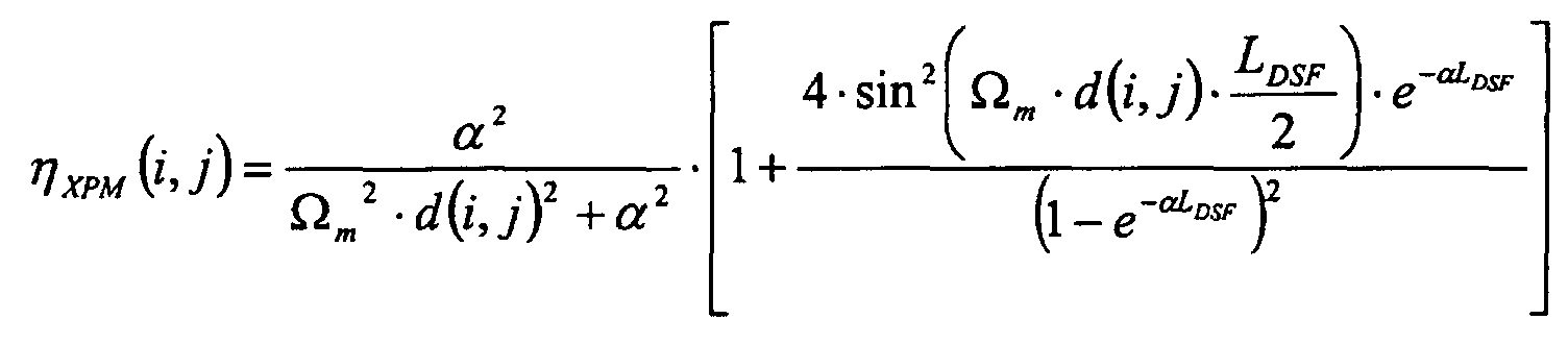
- An optical communication system according to claim 11, wherein two channels of signal light having respective wavelengths · 1 and · 2 propagate therethrough;
wherein the total phase shift amount · · XPM(1) resulting from the cross-phase modulation in signal light having the wavelength · 1 incident on said dispersion-shifted optical fiber under the influence of signal light having the wavelength · 2 is given by the following expression:
wherein the effective length Leff of said dispersion-shifted optical fiber and the efficiency of occurrence of cross-phase modulation · XPM (1,2) between the wavelengths · 1 and · 2 of signal light are given by the following expressions:where · is the transmission loss in said dispersion-shifted optical fiber, · m is the modulation frequency, and d(1,2) is the delay time difference per unit distance between the wavelengths · 1 and · 2 of signal light.
- An optical communication system according to claim 11, wherein said hybrid transmission unit satisfies the condition of:
- An optical communication system according to claim 11, wherein said hybrid transmission unit satisfies the condition of:
- An optical communication system according to claim 11, wherein said dispersion-shifted optical fiber has a positive dispersion with respect to light at a wavelength of 1.58 · m.
- An optical communication system according to claim 11, wherein one of said first and second high-dispersion optical fibers includes a single-mode optical fiber having a zero-dispersion wavelength in a 1.3-· m wavelength band, whereas the other includes a dispersion-compensating optical fiber for compensating for the dispersion of said single-mode optical fiber in the 1.55-· m wavelength band.
- An optical communication system according to claim 17, further comprising an optical amplifier, disposed in a transmission line through which light to enter said dispersion-shifted optical fiber propagates, for amplifying signal light in said signal light wavelength band, said dispersion-shifted optical fiber being disposed in a transmission line through which light to enter said optical amplifier propagates.
- An optical communication system according to claim 11, wherein, in said signal light wavelength band, each of said dispersion-shifted optical fiber and first high-dispersion optical fiber has a polarization mode dispersion of 2 ps· km-1/2 or less, and said second high-dispersion optical fiber has a polarization mode dispersion of 1 ps· km-1/2 or less.
- An optical communication system according to claim 11, wherein said hybrid transmission unit as a whole has an accumulated polarization dispersion of 1/(4B) or less in said signal light wavelength band.
Applications Claiming Priority (3)
| Application Number | Priority Date | Filing Date | Title |
|---|---|---|---|
| JP6167299 | 1999-03-09 | ||
| JP6167299 | 1999-03-09 | ||
| PCT/JP2000/001236 WO2000054439A1 (en) | 1999-03-09 | 2000-03-02 | Optical communication system |
Publications (1)
| Publication Number | Publication Date |
|---|---|
| EP1161009A1 true EP1161009A1 (en) | 2001-12-05 |
Family
ID=13177979
Family Applications (1)
| Application Number | Title | Priority Date | Filing Date |
|---|---|---|---|
| EP00906635A Withdrawn EP1161009A1 (en) | 1999-03-09 | 2000-03-02 | Optical communication system |
Country Status (5)
| Country | Link |
|---|---|
| US (1) | US6453103B1 (en) |
| EP (1) | EP1161009A1 (en) |
| AU (1) | AU2825700A (en) |
| TW (1) | TW463473B (en) |
| WO (1) | WO2000054439A1 (en) |
Cited By (1)
| Publication number | Priority date | Publication date | Assignee | Title |
|---|---|---|---|---|
| WO2002042815A3 (en) * | 2000-11-27 | 2003-03-13 | Nortel Networks Ltd | Dispersion managed optical fiber and system |
Families Citing this family (2)
| Publication number | Priority date | Publication date | Assignee | Title |
|---|---|---|---|---|
| JP4483041B2 (en) * | 2000-07-10 | 2010-06-16 | 住友電気工業株式会社 | Raman amplifier and Raman amplification transmission system |
| US7295584B2 (en) * | 2001-12-17 | 2007-11-13 | Peleton Photonic Systems | System and method for generating multi-wavelength laser source using highly nonlinear fiber |
Family Cites Families (15)
| Publication number | Priority date | Publication date | Assignee | Title |
|---|---|---|---|---|
| JP2743972B2 (en) | 1992-06-09 | 1998-04-28 | 国際電信電話株式会社 | Optical amplification repeater transmission method and system device |
| US6019873A (en) * | 1993-09-09 | 2000-02-01 | Marcal Paper Mills, Inc. | Floor absorbent granular product |
| US5539563A (en) * | 1994-05-31 | 1996-07-23 | At&T Corp. | System and method for simultaneously compensating for chromatic dispersion and self phase modulation in optical fibers |
| JPH08146472A (en) * | 1994-11-15 | 1996-06-07 | Nippon Telegr & Teleph Corp <Ntt> | Optical soliton communication method |
| JPH0923187A (en) | 1995-07-10 | 1997-01-21 | Fujitsu Ltd | Optical transmission system |
| CA2195614C (en) * | 1996-02-16 | 2005-06-28 | George F. Wildeman | Symmetric, dispersion-manager fiber optic cable and system |
| JP3503720B2 (en) * | 1996-05-01 | 2004-03-08 | 日本電信電話株式会社 | Soliton transmission line |
| CA2225889A1 (en) * | 1996-12-27 | 1998-06-27 | Sumitomo Electric Industries, Ltd. | Dispersion-shifted fiber |
| JP3418086B2 (en) * | 1997-05-09 | 2003-06-16 | 住友電気工業株式会社 | Optical transmission line for wavelength division multiplexing transmission and method of configuring the same |
| JPH1117624A (en) * | 1997-06-20 | 1999-01-22 | Sumitomo Electric Ind Ltd | Optical transmission line |
| JPH1137837A (en) * | 1997-07-18 | 1999-02-12 | Sekonitsuku:Kk | Exposure meter provided with internal illuminating display part |
| ID22381A (en) * | 1997-12-05 | 1999-10-07 | Sumitomo Electric Industries | OPTICAL FIBER WITH CONNECTION |
| CA2333477A1 (en) * | 1999-04-01 | 2000-10-12 | Sumitomo Electric Industries, Ltd. | Wdm optical communication system |
| JP2001091761A (en) * | 1999-09-27 | 2001-04-06 | Sumitomo Electric Ind Ltd | Optical fiber transmission line |
| US6496615B2 (en) * | 2000-05-22 | 2002-12-17 | Sumitomo Electric Industries, Ltd. | WDM transmission system |
-
2000
- 2000-03-02 EP EP00906635A patent/EP1161009A1/en not_active Withdrawn
- 2000-03-02 WO PCT/JP2000/001236 patent/WO2000054439A1/en not_active Application Discontinuation
- 2000-03-02 AU AU28257/00A patent/AU2825700A/en not_active Abandoned
- 2000-03-02 TW TW089103666A patent/TW463473B/en not_active IP Right Cessation
-
2001
- 2001-04-13 US US09/833,619 patent/US6453103B1/en not_active Expired - Fee Related
Non-Patent Citations (1)
| Title |
|---|
| See references of WO0054439A1 * |
Cited By (1)
| Publication number | Priority date | Publication date | Assignee | Title |
|---|---|---|---|---|
| WO2002042815A3 (en) * | 2000-11-27 | 2003-03-13 | Nortel Networks Ltd | Dispersion managed optical fiber and system |
Also Published As
| Publication number | Publication date |
|---|---|
| TW463473B (en) | 2001-11-11 |
| US6453103B1 (en) | 2002-09-17 |
| AU2825700A (en) | 2000-09-28 |
| WO2000054439A1 (en) | 2000-09-14 |
| US20020044752A1 (en) | 2002-04-18 |
Similar Documents
| Publication | Publication Date | Title |
|---|---|---|
| Cartaxo | Cross-phase modulation in intensity modulation-direct detection WDM systems with multiple optical amplifiers and dispersion compensators | |
| EP0703680B1 (en) | Apparatus and method for compensating chromatic dispersion produced in optical phase conjugation or other types of optical signal conversion | |
| US6487005B2 (en) | Optical fiber transmission system with chromatic dispersion compensation | |
| US7043099B1 (en) | Device and system for phase conjugate conversion and wavelength conversion | |
| EP2083320B1 (en) | Optical signal processing apparatus, optical receiving apparatus, and optical relay apparatus | |
| Kaler et al. | Comparison of pre-, post-and symmetrical-dispersion compensation schemes for 10 Gb/s NRZ links using standard and dispersion compensated fibers | |
| EP0862078A1 (en) | Optical fiber communication system using optical phase conjugate, apparatus applicable to the system and its manufacturing method | |
| JPH0798464A (en) | Optical communication system compensating wavelength dispersion and phase conjugate light generator applicable to this system | |
| US6687433B2 (en) | WDM optical communication system | |
| US6483633B2 (en) | Raman amplifier | |
| JP2000299660A (en) | Wavelength division multiplex optical transmission system, optical amplifier and dispersion compensator | |
| EP1404038A1 (en) | Method for reduction of non-linear distortions in an optical transmission channel | |
| Gnauck et al. | Dispersion and dispersion-slope compensation of NZDSF for 40-Gb/s operation over the entire C band | |
| JP4040583B2 (en) | Optical transmission system | |
| EP1161009A1 (en) | Optical communication system | |
| Ramachandran et al. | 1700-km transmission at 40-Gb/s with 100 km amplifier-spacing enabled by higher-order-mode dispersion-compensation | |
| EP1488551B1 (en) | Optical transmission system using an optical phase conjugation device | |
| Woods et al. | Reduction of cross-phase modulation-induced impairments in long-haul WDM telecommunication systems via spectral inversion | |
| EP1576747B1 (en) | Optical transmission system using an optical phase conjugation device | |
| JP3913804B2 (en) | Optical fiber communication system using optical phase conjugation. | |
| JP2000357992A (en) | Optical transmission line and optical transmission system | |
| EP1294114A1 (en) | Wdm transmission system | |
| Moro et al. | 720-ns continuously tunable parametric delay of a 10-Gb/s optical signal | |
| Gangwar et al. | Performance evaluation of 20 Gbps single-channel dispersion-managed soliton transmission | |
| Xie et al. | Signal distortion compensation by midspan spectral inversion in high-speed optical communication systems |
Legal Events
| Date | Code | Title | Description |
|---|---|---|---|
| PUAI | Public reference made under article 153(3) epc to a published international application that has entered the european phase |
Free format text: ORIGINAL CODE: 0009012 |
|
| 17P | Request for examination filed |
Effective date: 20010830 |
|
| AK | Designated contracting states |
Kind code of ref document: A1 Designated state(s): AT BE CH CY DE DK ES FI FR GB GR IE IT LI LU MC NL PT SE |
|
| RBV | Designated contracting states (corrected) |
Designated state(s): DE FR GB IT |
|
| STAA | Information on the status of an ep patent application or granted ep patent |
Free format text: STATUS: THE APPLICATION HAS BEEN WITHDRAWN |
|
| 18W | Application withdrawn |
Effective date: 20051004 |