EP1160971A2 - Negative feed-back amplifier and method for negative feed-back - Google Patents
Negative feed-back amplifier and method for negative feed-back Download PDFInfo
- Publication number
- EP1160971A2 EP1160971A2 EP01113398A EP01113398A EP1160971A2 EP 1160971 A2 EP1160971 A2 EP 1160971A2 EP 01113398 A EP01113398 A EP 01113398A EP 01113398 A EP01113398 A EP 01113398A EP 1160971 A2 EP1160971 A2 EP 1160971A2
- Authority
- EP
- European Patent Office
- Prior art keywords
- signal
- negative feed
- output
- amplifier
- feed
- Prior art date
- Legal status (The legal status is an assumption and is not a legal conclusion. Google has not performed a legal analysis and makes no representation as to the accuracy of the status listed.)
- Withdrawn
Links
- 238000000034 method Methods 0.000 title claims description 7
- 230000005669 field effect Effects 0.000 claims description 4
- 230000002238 attenuated effect Effects 0.000 abstract description 5
- 238000010586 diagram Methods 0.000 description 16
- 229920006395 saturated elastomer Polymers 0.000 description 4
- 230000005540 biological transmission Effects 0.000 description 3
- 230000000295 complement effect Effects 0.000 description 1
- 230000003247 decreasing effect Effects 0.000 description 1
- 230000000694 effects Effects 0.000 description 1
- 230000001131 transforming effect Effects 0.000 description 1
Images



Classifications
-
- H—ELECTRICITY
- H03—ELECTRONIC CIRCUITRY
- H03F—AMPLIFIERS
- H03F1/00—Details of amplifiers with only discharge tubes, only semiconductor devices or only unspecified devices as amplifying elements
- H03F1/34—Negative-feedback-circuit arrangements with or without positive feedback
-
- H—ELECTRICITY
- H03—ELECTRONIC CIRCUITRY
- H03F—AMPLIFIERS
- H03F1/00—Details of amplifiers with only discharge tubes, only semiconductor devices or only unspecified devices as amplifying elements
- H03F1/32—Modifications of amplifiers to reduce non-linear distortion
- H03F1/3217—Modifications of amplifiers to reduce non-linear distortion in single ended push-pull amplifiers
-
- H—ELECTRICITY
- H03—ELECTRONIC CIRCUITRY
- H03F—AMPLIFIERS
- H03F1/00—Details of amplifiers with only discharge tubes, only semiconductor devices or only unspecified devices as amplifying elements
- H03F1/30—Modifications of amplifiers to reduce influence of variations of temperature or supply voltage or other physical parameters
- H03F1/307—Modifications of amplifiers to reduce influence of variations of temperature or supply voltage or other physical parameters in push-pull amplifiers
Definitions
- the present invention relates to a negative feed-back amplifier and more particularly to the negative feed-back amplifier that can be suitably used in a video IF (Intermediate Frequency) amplifier installed on a video signal circuit of a television and to a method for negative feed-back.
- IF Intermediate Frequency
- a picture signal related circuit of a television is provided with a tuner 1, a band-pass filter (hereinafter referred to as a BPF 2), a local oscillator 3, a mixer 4, an immediate frequency preamplifier (hereinafter referred to as an IF frequency preamplifier 5), a condenser 6, and an intermediate frequency main amplifier (hereinafter referred simply to as an IF main amplifier 7).
- the IF preamplifier 5, the condenser 6, and a negative feed-back amplifier (the IF main amplifier 7) make up a video IF amplifier.
- Figure 9 is a circuit diagram showing electrical configurations of the IF main amplifier 7 shown in Fig. 8.
- the IF main amplifier 7 is provided with a bipolar transistor (hereinafter referred to a transistor 7a), a resistor 7b, a resistor 7c, a transistor 7d, a transistor 7e, a resistor 7f, a resistor 7g, and a resistor 7h.
- a receiving signal received by an antenna is input to the tuner 1 and a video intermediate frequency signal V1 is output from the tuner 1.
- the video intermediate frequency signal V1 is then input to the BPF 2 and an output signal V2 in a predetermined frequency band is output.
- the output signal V2 is mixed with an output signal V3 fed from the local oscillator 3 by the mixer 4 and an output signal V4 is output from the mixer 4.
- the output signal V4 is amplified by the IF preamplifier 5 and an output signal V5 is output from the IF preamplifier 5.
- the output signal V5 is input to the IF main amplifier 7 through the condenser 6 and amplified and then a video detecting signal "OUT" is output from the IF main amplifier 7.
- the video detecting signal "OUT" is transmitted to a video detecting amplifier (not shown).
- a video detecting amplifier (not shown).
- an output impedance of the IF main amplifier 7 is determined by the resistor 7f and a resistance of the resistor 7f is set to a value that does not cause the video detecting signal "OUT" to occur, with considerations given to a state of matching with a characteristic impedance of a transmission line connected to an output of the IF main amplifier 7 and with an input impedance of the video detecting amplifier (not shown).
- the video detecting signal "OUT" is fed back to a base of the transistor 7a through the resistor 7h.
- a negative feed-back amplifier including:
- a negative feed-back amplifier including:
- a negative feed-back amplifier including:
- a negative feed-back amplifier including :
- a negative feed-back amplifier including :
- a negative feed-back amplifier including :
- a preferable mode is one wherein the impedance converting means is made up of an emitter follower of a bipolar transistor or a source follower of an FET (Field Effect Transistor).
- the impedance converting means is made up of an emitter follower of a bipolar transistor or a source follower of an FET (Field Effect Transistor).
- a negative feed-back method including : a step of biasing a base of a bipolar transistor at an initial stage of a push-pull amplifier by using a negative feed-back signal which is produced by attenuation of an output signal at a predetermined feedback ratio in the push-pull amplifier made up of bipolar transistors and used to amplify an input signal and to output the output signal.
- a negative feed-back method including : a step of biasing a base of a bipolar transistor at an initial stage of a push-pull amplifier by using a negative feed-back signal which is produced by attenuation of a signal corresponding to an output signal at a predetermined feedback ratio in the push-pull amplifier made up of a bipolar transistor and used to amplify an input signal and to output the output signal.
- the output signal from the push-pull amplifier is attenuated by a feedback ratio setting circuit and is fed back to a base of a phase inverter amplifier, thus allowing proper setting of a base bias voltage of the bipolar transistor.
- This enables a dynamic range of the phase inverter amplifier to be made larger and distortion of the output signal to be reduced and, therefore, when this negative feed-back amplifier is used as a video IF amplifier in televisions, it serves to improve an image quality of the televisions.
- the output signal is input to an impedance converting means and, as a result, a load is taken off an output circuit and distortion of output signals can be reduced.
- the negative feed-back circuit is mounted independently of the output circuit and, therefore, even if feedback ratio is increased, the bipolar transistor of the output circuit is not easily saturated, thus serving to increase load driving capability and to make calibration of output impedance easier.
- the output circuit is made up of a push-pull type circuit in which a reversed signal is input at high input impedance and output at low output impedance, thus making it possible to make up a comparatively simpler negative feed-back amplifier.
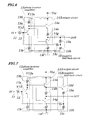
- FIG. 1 is a schematic circuit diagram showing electrical configurations of a negative feed-back amplifier according to a first embodiment of the present invention.
- the negative feed-back amplifier of the first embodiment includes, as shown in Fig. 1, an input terminal 11, a resistor 12, a phase inverter amplifier 13, an output circuit 14, and a negative feed-back circuit 15.
- the phase inverter amplifier 13 has an npn-type transistor 13a, a resistor 13b, and a resistor 13c, which is used to amplify an input signal "IN” and to produce a reversed signal V13a of a phase opposite to the input signal "IN” and a non-reversed signal V13b being in phase with the input signal "IN”.
- the output circuit 14 has an npn-type 14a, a resistor 14b, a condenser 14c, a bias circuit 14d, an npn-type transistor 14e and a resistor 14f, which is used to input the reversed signal V13a at high input impedance and to output it at low output impedance and, by reversing the non-reversed signal V13b and by outputting it, to produce an output signal "OUT" of a phase opposite to the input signal "IN”.
- the negative feed-back circuit 15 has resistors 15a and 15b operated to attenuate the output signal "OUT" at a feedback ratio and to produce a negative feed-back signal V15, which is used to add the negative feed-back signal V15 to the input signal "IN" through the resistor 15c.
- the resistors 15a and 15b make up a feedback ratio setting circuit.
- FIG. 2 is a circuit diagram showing one example of the bias circuit 14d shown in Fig. 1.
- the bias circuit 14d includes a resistor d1, transistors d2, d3, and d4 connected to diodes and a resistor d5 and an operating point of the transistor 14e is set in a start-up range.
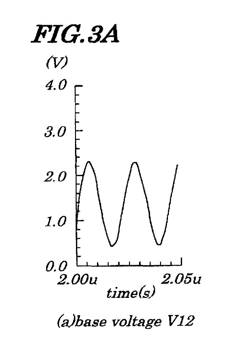
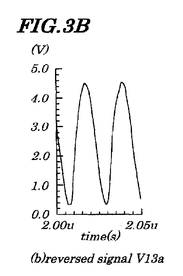
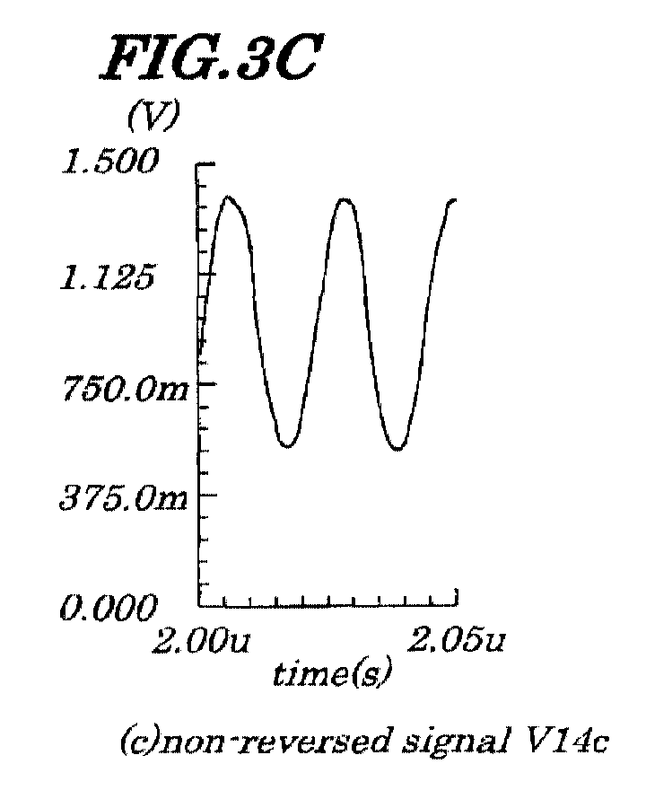
- Figures 3A, 3B, 3C, and 3D are wave-form diagrams of each of signals explaining operations of the negative feed-back amplifier according to the first embodiment of the present invention, in which a voltage is plotted as ordinate and time as abscissa. The operations of the negative feed-back amplifier are explained by referring to these figures.
- the input signal "IN” is input through the input terminal 11 and the resistor 12 to a base of the transistor 13a and a base voltage V12 (Fig. 1) as shown in Fig. 3A is generated.
- the reversed signal V13a as shown in Fig. 3B is output from a collector of the transistor 13a and the non-reversed signal V13b is output from an emitter of the transistor 13a.
- the reversed signal V13a is input, at high input impedance, to a base of the transistor 14a and is output, at low output impedance, from an emitter of the transistor 14a through the resistor 14b.
- the non-reversed signal V13b is input, as a non-reversed signal V14c as shown in Fig.
- the output impedance of the negative feed-back amplifier is determined by combining a serial resistance of the resistors 15a and 15b with the resistance of the resistor 14b, and parallel resistance is so set as to prevent an occurrence of reflection of the output signal "OUT" with considerations given to matching with a characteristic impedance or a load impedance of a transmission line connected to an output side of the negative feed-back circuit 15.
- the output signal "OUT" is attenuated by the resistors 15a and 15b and, as a result, the negative feed-back signal V15 is generated.
- the negative feed-back signal V15 is input to a base of the transistor 13a through the resistor 15c and is added to the input signal "IN". At this point, a base bias voltage is set properly and a dynamic range is made larger, thus minimizing distortion of signals.
- the base bias voltage of the transistor 13a is properly set. This causes a dynamic range of the phase inverter amplifier 13 to be made larger and distortion of signals to be reduced and, as a result, if this negative feed-back amplifier is used in a video IF amplifier, image quality of televisions is improved.
- FIG. 4 is a schematic circuit diagram showing electric configurations of a negative feed-back amplifier according to a second embodiment of the present invention.
- same reference numbers as those in the first embodiment are assigned to components having the same functions as in Fig. 1.
- the negative feed-back amplifier of the second embodiment is provided with a negative feed-back circuit 15A having configurations being different from a negative feed-back circuit 15 shown in Fig. 1.
- the negative feed-back circuit 15A has a transistor 15d.
- a base of the transistor 15d is connected to an emitter of a transistor 14a and a collector of the transistor 15d is connected to a terminal for a supply voltage VCC and an emitter of the transistor 15d is connected to a resistor 15a.
- the transistor 15d is an impedance transforming unit (that is, an emitter follower) adapted to produce a feed-back signal V15d by inputting an output signal V14a output from the transistor 14a at high input impedance and outputting at low output impedance.
- Other configurations are the same as those in Fig. 1.
- a waveform of each of signals is the same as shown in the first embodiment.
- operations of the negative feed-back amplifier of the second embodiment are different in following points. That is, since the output signal V14a output from the transistor 14a is input at high input impedance to a base of the transistor 15d, loads on the transistor 14a are removed and distortions of the output signal V14a are reduced. Even if a feed-back ratio is increased by decreasing a resistance of the resistor 15a, since there is no influence on a voltage of a collector of a transistor 14e, that is, voltage does not fall, the transistor 14e is not easily saturated, thus serving to increased load driving capacity.
- output impedance of the negative feed-back amplifier is determined by a resistance of a resistor 14b and there is no influence on the resistor 15a and a resistor 15b, thus allowing the negative feed-back amplifier to be adjusted independently.
- Output impedance is so set as to prevent occurrence of reflection of an output signal "OUT" with considerations given to matching with characteristic impedance or load impedance of a transmission line connected to an output side of the negative feed-back circuit 15A.
- the negative feed-back amplifier of the second embodiment since the output signal V14a is input to an emitter follower of the transistor 15d, load is taken off the transistor 14a, thus distortion of the output signal V14a can be reduced. This is an advantage added to those in the first embodiment. Moreover, since the negative feed-back circuit 15A is mounted independently of an output circuit 14, even if the feedback ratio increases, a voltage of a collector of the transistor 14e does not drop and therefore the transistor 14e is not easily saturated, thus increasing load driving capacity and making calibration of output impedance easier.
- Figure 6 is a schematic circuit diagram showing electric configurations of a negative feed-back amplifier according to a third embodiment of the present invention.
- same reference numbers as those in the first embodiment are assigned to components having the same functions as in Fig. 1.
- an output circuit 14A is mounted which has a configuration being different from an output circuit 14 in Fig. 1.
- a pnp-type transistor 14g instead of an npn-type transistor 14e in Fig. 1, is mounted so as to make up a complementary emitter follower.
- a collector of a transistor 13a is connected to a base of the pnp-type transistor 14g and a condenser 14c and bias circuit 14d shown in Fig. 1 are omitted.
- Other configurations in Fig. 6 are the same as those shown in Fig. 1.
- a reversed signal V13a is output from a collector of the transistor 13a and output reversed signal V13a is input to a base of the transistor 14a at high input impedance and, then, the reversed signal V13a is input to a base of the pnp-type transistor 14g at high input impedance. Operations thereafter are the same as in the case of the first embodiment.
- Figure 7 is a schematic circuit diagram showing electric configurations of a negative feed-back amplifier according to a fourth embodiment of the present invention.
- same reference numbers are assigned to components having the same functions in the second and third embodiments shown in Fig. 4 and in Fig. 6 respectively.
- an output circuit 14A is provided which has a configuration being an same as the output circuit 14 in Fig. 6, instead of the output circuit 14 in Fig. 4.
- Other configurations in Fig. 7 are the same as those in Fig. 4.
- a reversed signal V13a is output from a collector of a transistor 13a.
- the output reversed signal V13a is input to a base of a transistor 14a at high input impedance.
- the reversed signal V13a is input to a base of a transistor 14g at high input impedance. Operations thereafter are the same as in a case of the second embodiment.
- an impedance converting means is made up of an emitter follower of a transistor 15d, it may be made up of a source follower of an FET (Field Effect Transistor) .
- collectors of the transistor 15d shown in Fig. 4 and Fig. 7 may be connected to a terminal of an other supply power having a same ground as a supply power VCC.
Landscapes
- Engineering & Computer Science (AREA)
- Power Engineering (AREA)
- Physics & Mathematics (AREA)
- Nonlinear Science (AREA)
- Amplifiers (AREA)
- Picture Signal Circuits (AREA)
- Television Receiver Circuits (AREA)
Abstract
A negative feed-back amplifier is provided in which a
distortion of signals is reduced and a dynamic range is increased.
An input signal (in) is input to a base of a transistor (13a)
and is output from a collector as a reversed signal (V13a) and
a non-reversed signal (V13b) is output from an emitter. The
reversed signal (V13a) is input to a base of a transistor (14a)
and is output through a resistor (14b) from an emitter of the
transistor (14a). The non-reversed signal (V13b) is input through
a condenser (14c) to a base of a transistor (14e) and is output
from a collector in a reversed form. An output signal (V14a) from
the transistor (14a) is input to an emitter follower of a
transistor (15d) at high input impedance and output at low output
impedance and then attenuated by resistors (15a, 15b) and negative
feed-back signal (V15) is produced. The negative feed-back signal
(V15) is input through a resistor (15c) to a base of the transistor
(13a) to be added to the input signal (in).
Description
- The present invention relates to a negative feed-back amplifier and more particularly to the negative feed-back amplifier that can be suitably used in a video IF (Intermediate Frequency) amplifier installed on a video signal circuit of a television and to a method for negative feed-back.
- The present application claims priority of Japanese Patent Application No.2000-166868 filed on June 2,2000, which is hereby incorporated by reference.
- As shown in Fig. 8, a picture signal related circuit of a television is provided with a
tuner 1, a band-pass filter (hereinafter referred to as a BPF 2), alocal oscillator 3, amixer 4, an immediate frequency preamplifier (hereinafter referred to as an IF frequency preamplifier 5), a condenser 6, and an intermediate frequency main amplifier (hereinafter referred simply to as an IF main amplifier 7). The IF preamplifier 5, the condenser 6, and a negative feed-back amplifier (the IF main amplifier 7) make up a video IF amplifier. - Figure 9 is a circuit diagram showing electrical configurations of the IF
main amplifier 7 shown in Fig. 8. The IFmain amplifier 7 is provided with a bipolar transistor (hereinafter referred to atransistor 7a), aresistor 7b, aresistor 7c, atransistor 7d, atransistor 7e, aresistor 7f, a resistor 7g, and aresistor 7h. - In the picture signal related circuit, a receiving signal received by an antenna (not shown) is input to the
tuner 1 and a video intermediate frequency signal V1 is output from thetuner 1. The video intermediate frequency signal V1 is then input to theBPF 2 and an output signal V2 in a predetermined frequency band is output. The output signal V2 is mixed with an output signal V3 fed from thelocal oscillator 3 by themixer 4 and an output signal V4 is output from themixer 4. The output signal V4 is amplified by theIF preamplifier 5 and an output signal V5 is output from theIF preamplifier 5. The output signal V5 is input to the IFmain amplifier 7 through the condenser 6 and amplified and then a video detecting signal "OUT" is output from the IFmain amplifier 7. The video detecting signal "OUT" is transmitted to a video detecting amplifier (not shown). In this case, as shown in Fig. 9, an output impedance of the IFmain amplifier 7 is determined by theresistor 7f and a resistance of theresistor 7f is set to a value that does not cause the video detecting signal "OUT" to occur, with considerations given to a state of matching with a characteristic impedance of a transmission line connected to an output of the IFmain amplifier 7 and with an input impedance of the video detecting amplifier (not shown). Moreover, the video detecting signal "OUT" is fed back to a base of thetransistor 7a through theresistor 7h. - However, in the conventional IF
main amplifier 7, since, depending on set values of theresistors transistor 7a becomes too high and a dynamic range in a first stage becomes small; if an input signal "IN" is large, in some cases, a distortion of the video detecting signal "OUT" increases. This presents a problem in that an image quality of the television deteriorates. - In view of the above, it is an object of the present invention to provide a negative feed-back amplifier and a method for negative feed-back which are capable of preventing a distortion of a signal even if an input signal is large.
- According to a first aspect of the present invention, there is provided a negative feed-back amplifier including:
- a push-pull amplifier made up of a bipolar transistor and used to amplify an input signal and to output an output signal; and
- a negative feed-back circuit used to bias a base of the bipolar transistor at an initial stage of the push-pull amplifier by using a negative feed-back signal produced by attenuation of the output signal at a predetermined feedback ratio.
-
- According to a second aspect of the present invention, there is provided a negative feed-back amplifier including:
- a push-pull amplifier made up of a bipolar transistor and used to amplify an input signal and to output an output signal; and
- a negative feed-back circuit used to bias a base of the bipolar transistor at an initial stage of the push-pull amplifier by using a negative feed-back signal produced by attenuation of a signal corresponding to the output signal at a predetermined feedback ratio.
-
- According to a third aspect of the present invention, there is provided a negative feed-back amplifier including:
- a phase inverter amplifier used to amplify an input signal and to produce a reversed signal of a phase opposite to the input signal and to produce a non-reversed signal being in phase with the input signal;
- a push-pull output circuit used to produce an output signal of a phase opposite to the input signal by inputting the reversed signal at high input impedance and outputting the reversed signal at low output impedance and outputting the non-reversed signal in a reversed state;
- a negative feed-back circuit used to produce a negative feed-back signal by inputting the output signal and to add the negative feed-back signal to the input signal; and
- wherein the negative feed-back circuit is provided with a feedback ratio setting circuit used to attenuate the output signal at a predetermined feedback ratio and to produce the negative feed-back signal.
-
- According to a fourth aspect of the present invention, there is provided a negative feed-back amplifier including :
- a phase inverter amplifier used to amplify an input signal and to produce a reversed signal of a phase opposite to the input signal and to produce a non-reversed signal being in phase with the input signal;
- a push-pull output circuit used to produce an output signal of a phase opposite to the input signal by inputting the reversed signal aL high input impedance and outputting the reversed signal at low output impedance and outputting the non-reversed signal in a reversed state;
- a negative feed-back circuit used to produce a negative feed-back signal by inputting the output signal and to add the negative feed-back signal to the input signal; and
- wherein the negative feed-back circuit has an impedance converting means used to produce a feed-back signal by inputting the output signal at high input impedance and outputting the output signal at low output impedance and a feed-back ratio setting circuit used to produce the negative feed-back signal by attenuating the feed-back signal at a predetermined feed-back ratio.
-
- According to a fifth aspect of the present invention, there is provided a negative feed-back amplifier including :
- a phase inverter amplifier used to amplify an input signal and to produce a reversed signal of a phase opposite to the input signal;
- a push-pull output circuit used to produce an output signal of a phase opposite to the input signal by inputting the reversed signal at high input impedance and outputting the reversed signal at low output impedance;
- a negative feed-back circuit used to produce a negative feed-back signal by inputting the output signal and to add the negative feed-back signal to the input signal; and
- wherein the negative feed-back circuit is provided with a feedback ratio setting circuit used to attenuate the output signal at a predetermined feedback ratio and to produce the negative feed-back signal.
-
- According to a sixth aspect of the present invention, there is provided a negative feed-back amplifier including :
- a phase inverter amplifier used to amplify an input signal and to produce a reversed signal of a phase opposite to the input signal;
- a push-pull output circuit used to produce an output signal of a phase opposite to the input signal by inputting the reversed signal at high input impedance and outputting the reversed signal at low output impedance;
- a negative feed-back circuit used to produce a negative feed-back signal by inputting the output signal and to add the negative feed-back signal to the input signal; and
- wherein the negative feed-back circuit has an impedance converting means used to produce a feed-back signal by inputting the output signal at high input impedance and outputting the output signal at low output impedance and a feed-back ratio setting circuit used to produce the negative feed-back signal by attenuating the feed-back signal at a predetermined feed-back ratio.
-
- In the foregoing, a preferable mode is one wherein the impedance converting means is made up of an emitter follower of a bipolar transistor or a source follower of an FET (Field Effect Transistor).
- According to a seventh aspect of the present invention, there is provided a negative feed-back method including :
a step of biasing a base of a bipolar transistor at an initial stage of a push-pull amplifier by using a negative feed-back signal which is produced by attenuation of an output signal at a predetermined feedback ratio in the push-pull amplifier made up of bipolar transistors and used to amplify an input signal and to output the output signal. - According to an eighth aspect of the present invention, there is provided a negative feed-back method including :
a step of biasing a base of a bipolar transistor at an initial stage of a push-pull amplifier by using a negative feed-back signal which is produced by attenuation of a signal corresponding to an output signal at a predetermined feedback ratio in the push-pull amplifier made up of a bipolar transistor and used to amplify an input signal and to output the output signal. - With the above configuration, the output signal from the push-pull amplifier is attenuated by a feedback ratio setting circuit and is fed back to a base of a phase inverter amplifier, thus allowing proper setting of a base bias voltage of the bipolar transistor. This enables a dynamic range of the phase inverter amplifier to be made larger and distortion of the output signal to be reduced and, therefore, when this negative feed-back amplifier is used as a video IF amplifier in televisions, it serves to improve an image quality of the televisions.
- With another configuration, the output signal is input to an impedance converting means and, as a result, a load is taken off an output circuit and distortion of output signals can be reduced.
- With still another configuration, the negative feed-back circuit is mounted independently of the output circuit and, therefore, even if feedback ratio is increased, the bipolar transistor of the output circuit is not easily saturated, thus serving to increase load driving capability and to make calibration of output impedance easier.
- With still another configuration, the output circuit is made up of a push-pull type circuit in which a reversed signal is input at high input impedance and output at low output impedance, thus making it possible to make up a comparatively simpler negative feed-back amplifier.
- The above and other objects, advantages and features of the present invention will be more apparent from the following description taken in conjunction with the accompanying drawings in which:
- Fig. 1 is a schematic circuit diagram showing electrical configurations of a negative feed-back amplifier according to a first embodiment of the present invention;
- Fig. 2 is a circuit diagram showing one example of a bias circuit shown in Fig. 1 according to the first embodiment of the present invention;
- Figs. 3A, 3B, 3C, and 3D are wave-form diagrams of each of signals explaining operations of the negative feed-back amplifier according to the first embodiment of the present invention;
- Fig. 4 is a schematic circuit diagram showing electric configurations of a negative feed-back amplifier according to a second embodiment of the present invention;
- Figs. 5A, 5B, 5C, and 5D are wave-form diagrams of each of signals explaining operations of the negative feed-back amplifier according to the second embodiment of the present invention;
- Fig. 6 is a schematic circuit diagram showing electric configurations of a negative feed-back amplifier according to a third embodiment of the present invention.
- Fig. 7 is a schematic circuit diagram showing electric configurations of a negative feed-back amplifier according to a fourth embodiment of the present invention;
- Fig. 8 is a schematic block diagram showing prior art picture signal related circuits of a television; and
- Fig. 9 is a circuit diagram showing electrical configurations of a prior art IF main amplifier shown in Fig. 8.
-
- Best modes of carrying out the present invention will be described in further detail using various embodiments with reference to the accompanying drawings.
- Figure 1 is a schematic circuit diagram showing electrical configurations of a negative feed-back amplifier according to a first embodiment of the present invention. The negative feed-back amplifier of the first embodiment includes, as shown in Fig. 1, an
input terminal 11, aresistor 12, aphase inverter amplifier 13, anoutput circuit 14, and a negative feed-back circuit 15. Thephase inverter amplifier 13 has an npn-type transistor 13a, aresistor 13b, and aresistor 13c, which is used to amplify an input signal "IN" and to produce a reversed signal V13a of a phase opposite to the input signal "IN" and a non-reversed signal V13b being in phase with the input signal "IN". Theoutput circuit 14 has an npn-type 14a, aresistor 14b, acondenser 14c, abias circuit 14d, an npn-type transistor 14e and aresistor 14f, which is used to input the reversed signal V13a at high input impedance and to output it at low output impedance and, by reversing the non-reversed signal V13b and by outputting it, to produce an output signal "OUT" of a phase opposite to the input signal "IN". The negative feed-back circuit 15 hasresistors resistor 15c. Theresistors - Figure 2 is a circuit diagram showing one example of the
bias circuit 14d shown in Fig. 1. Thebias circuit 14d includes a resistor d1, transistors d2, d3, and d4 connected to diodes and a resistor d5 and an operating point of thetransistor 14e is set in a start-up range. - Figures 3A, 3B, 3C, and 3D are wave-form diagrams of each of signals explaining operations of the negative feed-back amplifier according to the first embodiment of the present invention, in which a voltage is plotted as ordinate and time as abscissa. The operations of the negative feed-back amplifier are explained by referring to these figures.
- The input signal "IN" is input through the
input terminal 11 and theresistor 12 to a base of thetransistor 13a and a base voltage V12 (Fig. 1) as shown in Fig. 3A is generated. The reversed signal V13a as shown in Fig. 3B is output from a collector of thetransistor 13a and the non-reversed signal V13b is output from an emitter of thetransistor 13a. The reversed signal V13a is input, at high input impedance, to a base of thetransistor 14a and is output, at low output impedance, from an emitter of thetransistor 14a through theresistor 14b. The non-reversed signal V13b is input, as a non-reversed signal V14c as shown in Fig. 3C, to a base of the npn-type transistor 14e through thecondenser 14c and is output, in an inverted state, from a collector of the npn-type transistor 14e. Therefore, an output signal "OUT" of a phase opposite to the input signal "IN" as shown in Fig. 3D is output. At this point, the output impedance of the negative feed-back amplifier is determined by combining a serial resistance of theresistors resistor 14b, and parallel resistance is so set as to prevent an occurrence of reflection of the output signal "OUT" with considerations given to matching with a characteristic impedance or a load impedance of a transmission line connected to an output side of the negative feed-back circuit 15. - Moreover, the output signal "OUT" is attenuated by the
resistors transistor 13a through theresistor 15c and is added to the input signal "IN". At this point, a base bias voltage is set properly and a dynamic range is made larger, thus minimizing distortion of signals. - Thus, according to the first embodiment, since the output signal "OUT" is attenuated by the
resistors transistor 13a, the base bias voltage of thetransistor 13a is properly set. This causes a dynamic range of thephase inverter amplifier 13 to be made larger and distortion of signals to be reduced and, as a result, if this negative feed-back amplifier is used in a video IF amplifier, image quality of televisions is improved. - Figure 4 is a schematic circuit diagram showing electric configurations of a negative feed-back amplifier according to a second embodiment of the present invention. In Fig. 4, same reference numbers as those in the first embodiment are assigned to components having the same functions as in Fig. 1. The negative feed-back amplifier of the second embodiment is provided with a negative feed-
back circuit 15A having configurations being different from a negative feed-back circuit 15 shown in Fig. 1. The negative feed-back circuit 15A has atransistor 15d. A base of thetransistor 15d is connected to an emitter of atransistor 14a and a collector of thetransistor 15d is connected to a terminal for a supply voltage VCC and an emitter of thetransistor 15d is connected to aresistor 15a. Thetransistor 15d is an impedance transforming unit (that is, an emitter follower) adapted to produce a feed-back signal V15d by inputting an output signal V14a output from thetransistor 14a at high input impedance and outputting at low output impedance. Other configurations are the same as those in Fig. 1. - As shown in Figures 5A, 5B, 5C, and 5D, a waveform of each of signals is the same as shown in the first embodiment. However, operations of the negative feed-back amplifier of the second embodiment are different in following points. That is, since the output signal V14a output from the
transistor 14a is input at high input impedance to a base of thetransistor 15d, loads on thetransistor 14a are removed and distortions of the output signal V14a are reduced. Even if a feed-back ratio is increased by decreasing a resistance of theresistor 15a, since there is no influence on a voltage of a collector of atransistor 14e, that is, voltage does not fall, thetransistor 14e is not easily saturated, thus serving to increased load driving capacity. Since the negative feed-back circuit 15A is configured so as to be operated independently from theoutput circuit 14, output impedance of the negative feed-back amplifier is determined by a resistance of aresistor 14b and there is no influence on theresistor 15a and aresistor 15b, thus allowing the negative feed-back amplifier to be adjusted independently. Output impedance is so set as to prevent occurrence of reflection of an output signal "OUT" with considerations given to matching with characteristic impedance or load impedance of a transmission line connected to an output side of the negative feed-back circuit 15A. - As described above, according to the negative feed-back amplifier of the second embodiment, since the output signal V14a is input to an emitter follower of the
transistor 15d, load is taken off thetransistor 14a, thus distortion of the output signal V14a can be reduced. This is an advantage added to those in the first embodiment. Moreover, since the negative feed-back circuit 15A is mounted independently of anoutput circuit 14, even if the feedback ratio increases, a voltage of a collector of thetransistor 14e does not drop and therefore thetransistor 14e is not easily saturated, thus increasing load driving capacity and making calibration of output impedance easier. - Figure 6 is a schematic circuit diagram showing electric configurations of a negative feed-back amplifier according to a third embodiment of the present invention. In Fig. 6, same reference numbers as those in the first embodiment are assigned to components having the same functions as in Fig. 1. In the negative feed-back amplifier of the third embodiment shown in Fig. 6, an
output circuit 14A is mounted which has a configuration being different from anoutput circuit 14 in Fig. 1. In theoutput circuit 14A, a pnp-type transistor 14g, instead of an npn-type transistor 14e in Fig. 1, is mounted so as to make up a complementary emitter follower. Moreover, a collector of atransistor 13a is connected to a base of the pnp-type transistor 14g and acondenser 14c andbias circuit 14d shown in Fig. 1 are omitted. Other configurations in Fig. 6 are the same as those shown in Fig. 1. - In the negative feed-back amplifier of the embodiment, a reversed signal V13a is output from a collector of the
transistor 13a and output reversed signal V13a is input to a base of thetransistor 14a at high input impedance and, then, the reversed signal V13a is input to a base of the pnp-type transistor 14g at high input impedance. Operations thereafter are the same as in the case of the first embodiment. - Thus, since the
condenser 14c shown in Fig. 1 is omitted in the negative feed-back amplifier of the third embodiment, circuit configurations are made simpler compared with those in a case of the first embodiment. Moreover, since an output signal "OUT" is attenuated byresistors transistor 13a, the same effect as obtained in the first embodiment can be achieved. - Figure 7 is a schematic circuit diagram showing electric configurations of a negative feed-back amplifier according to a fourth embodiment of the present invention. In Fig. 7, same reference numbers are assigned to components having the same functions in the second and third embodiments shown in Fig. 4 and in Fig. 6 respectively. In the negative feed-back amplifier of the fourth embodiment shown in Fig. 7, an
output circuit 14A is provided which has a configuration being an same as theoutput circuit 14 in Fig. 6, instead of theoutput circuit 14 in Fig. 4. Other configurations in Fig. 7 are the same as those in Fig. 4. - In the negative feed-back amplifier of the fourth embodiment, a reversed signal V13a is output from a collector of a
transistor 13a. The output reversed signal V13a is input to a base of atransistor 14a at high input impedance. Then, the reversed signal V13a is input to a base of atransistor 14g at high input impedance. Operations thereafter are the same as in a case of the second embodiment. - Thus, since a
condenser 14c shown in Fig. 1 is omitted in the fourth embodiment as in a case of the third embodiment, circuit configurations are made simpler as compared with those in a case of the second embodiment. Moreover, as in the case of the second embodiment, since an output signal V14a is input from thetransistor 14a to an emitter follower of atransistor 15d, a load is taken off thetransistor 14a, thus distortion of the output signal V14a can be reduced. Moreover, even if feedback ratio increases, a voltage of a collector of atransistor 14e does not drop and therefore thetransistor 14e is not easily saturated, thus increasing load driving capacity. Since a negative feed-back circuit 15A is mounted independently of theoutput circuit 14, output impedance can be easily calibrated. - It is apparent that the present invention is not limited to the above embodiments but may be changed and modified without departing from the scope and spirit of the invention. For example, in the second and fourth embodiments, though an impedance converting means is made up of an emitter follower of a
transistor 15d, it may be made up of a source follower of an FET (Field Effect Transistor) . Moreover, collectors of thetransistor 15d shown in Fig. 4 and Fig. 7 may be connected to a terminal of an other supply power having a same ground as a supply power VCC.
Claims (10)
- A negative feed-back amplifier characterized by comprising:a push-pull amplifier (13, 14; 13, 14A) made up of bipolar transistors (13a, 14a, 14e) and used to amplify an input signal and to output an output signal; anda negative feed-back circuit (15; 15A) used to bias a base of a bipolar transistor (13a) at an initial stage of said push-pull amplifier by using a negative feed-back signal produced by attenuation of said output signal at a predetermined feedback ratio.
- A negative feed-back amplifier characterized by comprising:a push-pull amplifier made up of bipolar transistors (13a, 14a, 14e) and used to amplify an input signal and to output an output signal; anda negative feed-back circuit (15; 15A) used to bias a base of a bipolar transistor (13a) at an initial stage of push-pull said amplifier by using a negative feed-back signal produced by attenuation of a signal corresponding to the output signal at a predetermined feedback ratio.
- A negative feed-back amplifier characterized by comprising:a phase inverter amplifier (13) used to amplify an input signal and to produce a reversed signal of a phase opposite to said input signal and to produce a non-reversed signal being in phase with said input signal;a push-pull output circuit (14) used to produce an output signal of a phase opposite to said input signal by inputting said reversed signal at high input impedance and outputting said reversed signal at low output impedance and outputting said non-reversed signal in a reversed state;a negative feed-back circuit (15; 15A) used to produce a negative feed-back signal by inputting said output signal and to add said negative feed-back signal to said input signal; andwherein said negative feed-back circuit is provided with a feedback ratio setting circuit (15a, 15b) used to attenuate said output signal at a predetermined feedback ratio and to produce said negative feed-back signal.
- A negative feed-back amplifier characterized by comprising:a phase inverter amplifier (13) used to amplify an input signal and to produce a reversed signal of a phase opposite to said input signal and to produce a non-reversed signal being in phase with said input signal;a push-pull output circuit (14) used to produce an output signal of a phase opposite to said input signal by inputting said reversed signal at high input impedance and outputting said reversed signal at low output impedance and outputting said non-reversed signal in a reversed state;a negative feed-back circuit (15A) used to produce a negative feed-back signal by inputting said output signal and to add said negative feed-back signal to said input signal; andwherein said negative feed-back circuit (15A) has an impedance converting means (15d) used to produce a feed-back signal by inputting said output signal at high input impedance and outputting said output signal at low output impedance and a feed-back ratio setting circuit (15a, 15b) used to produce said negative feed-back signal by attenuating said feed-back signal at a predetermined feed-back ratio.
- The negative feed-back amplifier according to Claim 4, wherein said impedance converting means (15d) is made up of an emitter follower of a bipolar transistor or a source follower of an FET (Field Effect Transistor).
- A negative feed-back amplifier characterized by comprising:a phase inverter amplifier (13) used to amplify an input signal and to produce a reversed signal of a phase opposite to said input signal;a push-pull output circuit (14A) used to produce an output signal of a phase opposite to said input signal by inputting said reversed signal at high input impedance and outputting said reversed signal at low output impedance;a negative feed-back circuit (15; 15A) used to produce a negative feed-back signal by inputting said output signal and to add said negative feed-back signal to said input signal; andwherein said negative feed-back circuit (15; 15A) is provided with a feedback ratio setting circuit (15a, 15b) used to attenuate said output signal at a predetermined feedback ratio and to produce said negative feed-back signal.
- A negative feed-back amplifier characterized by comprising:a phase inverter amplifier (13) used to amplify an input signal and to produce a reversed signal of a phase opposite to said input signal;a push-pull output circuit (14A) used to produce an output signal of a phase opposite to said input signal by inputting said reversed signal at high input impedance and outputting said reversed signal at low output impedance;a negative feed-back circuit (15A) used to produce a negative feed-back signal by inputting said output signal and to add said negative feed-back signal to said input signal; andwherein said negative feed-back circuit (15A) has an impedance converting means (15d) used to produce a feed-back signal by inputting said output signal at high input impedance and outputting said output signal at low output impedance and a feed-back ratio setting circuit (15a, 15b) used to produce said negative feed-back signal by attenuating said feed-back signal at a predetermined feed-back ratio.
- The negative feed-back amplifier according to Claim 7, wherein said impedance converting means (15d) is made up of an emitter follower of a bipolar transistor or a source follower of an FET (Field Effect Transistor).
- A negative feed-back method characterized by comprising:
a step of biasing a base of a bipolar transistor (13a) at an initial stage of a push-pull amplifier (13, 14) by using a negative feed-back signal which is produced by attenuation of an output signal at a predetermined feedback ratio in said push-pull amplifier (13, 14) made up of bipolar transistors (13a, 14a, 14e) and used to amplify an input signal and to output said output signal. - A negative feed-back method characterized by comprising:
a step of biasing a base of a bipolar transistor (13a) at an initial stage of a push-pull amplifier (13, 14) by using a negative feed-back signal which is produced by attenuation of a signal corresponding to an output signal at a predetermined feedback ratio in said push-pull amplifier (13, 14) made up of bipolar transistors (13a, 14a, 14e) and used to amplify an input signal and to output said output signal.
Applications Claiming Priority (2)
| Application Number | Priority Date | Filing Date | Title |
|---|---|---|---|
| JP2000166868 | 2000-06-02 | ||
| JP2000166868A JP2001345646A (en) | 2000-06-02 | 2000-06-02 | Negative-feedback amplifier circuit and negative feedback method |
Publications (1)
| Publication Number | Publication Date |
|---|---|
| EP1160971A2 true EP1160971A2 (en) | 2001-12-05 |
Family
ID=18670119
Family Applications (1)
| Application Number | Title | Priority Date | Filing Date |
|---|---|---|---|
| EP01113398A Withdrawn EP1160971A2 (en) | 2000-06-02 | 2001-06-01 | Negative feed-back amplifier and method for negative feed-back |
Country Status (4)
| Country | Link |
|---|---|
| US (1) | US6593813B2 (en) |
| EP (1) | EP1160971A2 (en) |
| JP (1) | JP2001345646A (en) |
| KR (1) | KR100399561B1 (en) |
Families Citing this family (1)
| Publication number | Priority date | Publication date | Assignee | Title |
|---|---|---|---|---|
| KR100513970B1 (en) * | 2002-12-16 | 2005-09-13 | 학교법인 한국정보통신학원 | Source follower type preamplifier for improving bandwith |
Family Cites Families (6)
| Publication number | Priority date | Publication date | Assignee | Title |
|---|---|---|---|---|
| US3424992A (en) * | 1965-06-30 | 1969-01-28 | Us Navy | Wideband power amplifier |
| US3437944A (en) * | 1966-01-10 | 1969-04-08 | Mallory & Co Inc P R | Three-state amplifier |
| US3750039A (en) * | 1969-03-27 | 1973-07-31 | Sanders Associates Inc | Current steering amplifier |
| JPH05315862A (en) * | 1992-05-07 | 1993-11-26 | Nec Corp | Amplifier circuit |
| JPH05327362A (en) | 1992-05-22 | 1993-12-10 | Fujitsu Ten Ltd | Negative feedback power amplifier |
| JPH06326523A (en) | 1993-05-14 | 1994-11-25 | Pioneer Electron Corp | Multistage negative feedback amplifier circuit |
-
2000
- 2000-06-02 JP JP2000166868A patent/JP2001345646A/en not_active Withdrawn
-
2001
- 2001-06-01 US US09/872,730 patent/US6593813B2/en not_active Expired - Fee Related
- 2001-06-01 EP EP01113398A patent/EP1160971A2/en not_active Withdrawn
- 2001-06-02 KR KR10-2001-0031011A patent/KR100399561B1/en not_active Expired - Fee Related
Also Published As
| Publication number | Publication date |
|---|---|
| KR20010110187A (en) | 2001-12-12 |
| KR100399561B1 (en) | 2003-09-26 |
| US20010050594A1 (en) | 2001-12-13 |
| JP2001345646A (en) | 2001-12-14 |
| US6593813B2 (en) | 2003-07-15 |
Similar Documents
| Publication | Publication Date | Title |
|---|---|---|
| US5329189A (en) | Mixer circuit | |
| US4596045A (en) | Input circuit for television receiver | |
| EP1160971A2 (en) | Negative feed-back amplifier and method for negative feed-back | |
| US5003620A (en) | Tuner circuit and receiving band change-over circuit with a push-pull amplifier | |
| US20020191119A1 (en) | Tuner circuit | |
| US20020146992A1 (en) | Dynamic biasing of a transmitter | |
| JPS6247017B2 (en) | ||
| JP2004072451A (en) | Electronic tuner | |
| JPH10126215A (en) | Variable damping device | |
| KR20040078572A (en) | High frequency device | |
| EP1037386B1 (en) | Television tuner with suppressed attenuation of level of video intermediate frequency with respect to rise in ambient temperature | |
| KR880000812Y1 (en) | Image compensating circuit of a television sets | |
| KR960011410B1 (en) | Tuner High Frequency Input Signal Intensity Control Circuit | |
| KR900006312Y1 (en) | Video signal compensation device for TV / VTR device | |
| KR930003451Y1 (en) | Automatic image edge part gain control circuit | |
| EP0371447A2 (en) | Detector circuit | |
| JP2993496B1 (en) | Mixer with limiter circuit | |
| JPS61206325A (en) | television receiver | |
| JP3101450U (en) | Television tuner | |
| KR0178196B1 (en) | Tuner with Dual Gate MOSFET | |
| JP3282241B2 (en) | Signal switching circuit | |
| KR930007190Y1 (en) | De-emphasis for multi-sound broadcasting system | |
| KR100218088B1 (en) | Tuning video signal control circuit | |
| JPH0238522Y2 (en) | ||
| JPS61113370A (en) | Television receiver |
Legal Events
| Date | Code | Title | Description |
|---|---|---|---|
| PUAI | Public reference made under article 153(3) epc to a published international application that has entered the european phase |
Free format text: ORIGINAL CODE: 0009012 |
|
| AK | Designated contracting states |
Kind code of ref document: A2 Designated state(s): AT BE CH CY DE DK ES FI FR GB GR IE IT LI LU MC NL PT SE TR |
|
| AX | Request for extension of the european patent |
Free format text: AL;LT;LV;MK;RO;SI |
|
| RAP1 | Party data changed (applicant data changed or rights of an application transferred) |
Owner name: NEC COMPOUND SEMICONDUCTOR DEVICES, LTD. |
|
| RAP1 | Party data changed (applicant data changed or rights of an application transferred) |
Owner name: NEC ELECTRONICS CORPORATION |
|
| STAA | Information on the status of an ep patent application or granted ep patent |
Free format text: STATUS: THE APPLICATION HAS BEEN WITHDRAWN |
|
| 18W | Application withdrawn |
Effective date: 20070416 |