EP1160827A1 - Fluorescent lamp extension tube amalgam holder - Google Patents
Fluorescent lamp extension tube amalgam holder Download PDFInfo
- Publication number
- EP1160827A1 EP1160827A1 EP01304803A EP01304803A EP1160827A1 EP 1160827 A1 EP1160827 A1 EP 1160827A1 EP 01304803 A EP01304803 A EP 01304803A EP 01304803 A EP01304803 A EP 01304803A EP 1160827 A1 EP1160827 A1 EP 1160827A1
- Authority
- EP
- European Patent Office
- Prior art keywords
- cover
- mouth
- mounting portion
- extension
- amalgam
- Prior art date
- Legal status (The legal status is an assumption and is not a legal conclusion. Google has not performed a legal analysis and makes no representation as to the accuracy of the status listed.)
- Withdrawn
Links
Images


Classifications
-
- H—ELECTRICITY
- H01—ELECTRIC ELEMENTS
- H01J—ELECTRIC DISCHARGE TUBES OR DISCHARGE LAMPS
- H01J61/00—Gas-discharge or vapour-discharge lamps
- H01J61/02—Details
- H01J61/24—Means for obtaining or maintaining the desired pressure within the vessel
- H01J61/28—Means for producing, introducing, or replenishing gas or vapour during operation of the lamp
Definitions
- This invention relates to electric lamps and, in particular, to a holder for an amalgam in a gas discharge lamp.
- Maintaining mercury vapor pressure equilibrium within a gas discharge lamp such as a fluorescent lamp is necessary to maintain optimum lumen output during extended lamp on periods.
- the mercury vapor pressure increases to an optimum pressure allowing the lamp to reach maximum lumen output.
- the mercury vapor pressure increases to a level above the most preferable pressure causing the luminous flux to decrease.
- amalgams are introduced to maintain the mercury vapor pressure within an optimal range during lamp operation.
- the amalgam Upon lamp ignition, the amalgam is heated which causes mercury to diffuse out of the solid and is released into the lamp as vapor.
- the amalgam achieves mercury vapor equilibrium during lamp operation by supplying the same amount of mercury atoms to the interior of the lamp envelope as are spent.
- the decrease in temperature causes the mercury vapor to navigate to and diffuse into the amalgam causing mercury starvation.
- the lack of mercury vapor in the lamp envelope during off periods results in low lumens at lamp startup.
- an adequate dose of mercury vapor is required to remain in the lamp envelope during lamp off periods.
- a restricted fixed orifice in an amalgam capsule can be used to reduce the starvation effect for short off times.
- U.S. Patent No. 5,828,169 uses such a technique. However, during extended off times, virtually all of the mercury can still return to the amalgam.
- an amalgam holder for a discharge lamp having an exhaust tube and a flare pinched about the tube
- the holder includes an extension of the tube or flare having a cavity for an amalgam, the cavity having a mouth; and a cover for the mouth, the cover being thermally actuated.
- an amalgam holder 10 for a gas discharge lamp such as a fluorescent lamp includes an exhaust tube 12, a flare 14, two lead wires 16, 18, a cathode 20 between the lead wires 16, 18, an amalgam 22, an extension 24 and a cover or valve 26.
- the exhaust tube 12, the flare 14, the extension 24 may be formed, for example, from glass or a glass-like material.
- the leads 16, 18 and the cathode 20 are electrically conductive materials well-known in the art.
- the amalgam 22 is a metallic amalgam of, for example, mercury and other materials known in the art to be suitable for establishing a mercury (or other metallic ion) equilibrium during operation of a discharge lamp.
- the flare 14 is pinched over the leads 16, 18 and the exhaust tube 12 while the material of the flare and tube are in a softened state.
- the area where the flare 14 is pinched is called the pinch 28.
- the pinch 28 typically includes a vent 30 in communication with the interior of the exhaust tube 12.
- a discharge lamp typically has a tubular envelope (not shown) that is closed at the end by inserting the flare 14 into the envelope cathode-first and sealing the flare 14 to the envelope.
- the extension 24 can be advantageously formed from an extended portion of the tube 12 or it may be formed as an extension of the flare 14. If desired, the extension 24 could be formed from a separate piece of material. After pinching, there is little apparent difference.
- the extension 24 may be, for example, generally cylindrical with a generally cylindrical cavity 32 within.
- the amalgam 22 may be retained within the cavity 32 by a dimple 34, or the like, in the wall of the extension 24.
- the mouth 36 of the cavity 32 may also be narrowed to constrict mercury vapor flow and to allow more efficient covering of the mouth 36 with the cover 26.
- the cover 26 is a generally L-shaped piece of bimetal having a mounting portion 38 and a cover portion 40.
- the mounting portion 38 is attached to the lead wire 16 by, for example, welding.
- the cover portion 40 closes the mouth 36 when the cover 26 is cold.
- the cover 26 is heated and the cover portion 40 lifts off of the mouth 36, thereby opening the cavity 32 to the atmosphere inside the envelope.
- the cover 26 thus operates as a thermally actuated valve.
- the cover 26 When the lamp is at full operating temperature, the cover 26 has been heated by the cathode 20 and is open and the amalgam 22 establishes a desired mercury equilibrium inside the envelope. When the lamp is turned off, the cover 26 closes off the amalgam 22 from the atmosphere of the envelope thereby preventing the mercury in the envelope atmosphere from recombining with the amalgam 22. In this way, sufficient mercury remains in the envelope atmosphere to prevent mercury starvation during lamp startup.
- cover 26 in the preferred embodiment is heat actuated using a bimetallic element, it would also be possible to actuate the cover 26 with electrical, chemical, or other motive techniques.
- an additional embodiment of an amalgam holder 10' includes many of the previously described elements and operates in a similar manner.
- the bimetal cover 26' includes a mounting portion 38' and a cover portion 40'.
- the mounting portion 38' is a generally cylindrical sleeve and the cover portion 40' is a flap attached to the mouth end of the sleeve.
- the extension 24' includes a rolled in groove 42 to assist in retaining the cover 26' by engaging an annular lip 44 inside the mounting portion 38'.
- the cover portion 40' closes the mouth 36 when the cover 26' is cold.
- the cover 26' is heated and the cover portion 40' lifts off of the mouth 36, thereby opening the cavity 32 to the atmosphere inside the envelope.
- the cover 26' thus operates as a thermally actuated valve.
- an additional embodiment of an amalgam holder 10" includes many of the previously described elements and operates in a similar manner.
- the bimetal cover 26" includes a mounting portion 38", a cover portion 40" and a strip portion 46.
- the mounting portion 38" is a band seated in the groove 42 and the cover portion 40" is a flap connected to the mounting portion 38" by the strip portion 46. If the strip portion 46 is considered to be a remaining portion of a cylindrical sleeve, it would represent between 1 and 10 degrees of the sleeve, with 5 degrees being preferred.
- the cover 40" closes the mouth 36 when the cover 26" is cold.
- the cover 26" is heated and the cover portion 40" lifts off of the mouth 36, thereby opening the cavity 32 to the atmosphere inside the envelope.
- the cover 26" thus operates as a thermally actuated valve.
- FIGS. 3, 4, 5 and 6 each have a mounting portion that clasps the extension. While these embodiments completely encircle the extension, it is also possible to clasp the extension with embodiments that do not entirely encircle the extension. For example, if the mounting portion encircles greater than half of the circumference of the extension, the extension will still be clasped by the mounting portion.
- an additional embodiment of an amalgam holder 10"' includes many of the previously described elements and operates in a similar manner.
- the bimetal cover 26"' includes a mounting portion 38"' and a cover portion 40'''.
- the mounting portion 38"' is a V-shaped member that compresses when inserted in the mouth 36 and then expands to retain the cover 26"' on the extension 24.
- the mounting portion 38"' includes an aperture 48 to minimize the blocking of the mouth 36 with the mounting portion 38"'.
- the cover portion 40''' is a flap attached to the top of one leg of the V of the mounting portion 26"'.
- the cover portion 40 closes the mouth 36 when the cover 26"' is cold.
- the cover 26''' is heated and the cover portion 40"' lifts off of the mouth 36, thereby opening the cavity 32 to the atmosphere inside the envelope.
- the cover 26''' thus operates as a thermally actuated valve.
Abstract
Description
- This invention relates to electric lamps and, in particular, to a holder for an amalgam in a gas discharge lamp.
- Maintaining mercury vapor pressure equilibrium within a gas discharge lamp such as a fluorescent lamp is necessary to maintain optimum lumen output during extended lamp on periods. In conventional fluorescent lamps, the mercury vapor pressure increases to an optimum pressure allowing the lamp to reach maximum lumen output. As time passes, the mercury vapor pressure increases to a level above the most preferable pressure causing the luminous flux to decrease.
- To help maintain the pressure at the optimum pressure, amalgams are introduced to maintain the mercury vapor pressure within an optimal range during lamp operation. Upon lamp ignition, the amalgam is heated which causes mercury to diffuse out of the solid and is released into the lamp as vapor. The amalgam achieves mercury vapor equilibrium during lamp operation by supplying the same amount of mercury atoms to the interior of the lamp envelope as are spent. However, when the lamp is switched off, the decrease in temperature causes the mercury vapor to navigate to and diffuse into the amalgam causing mercury starvation. The lack of mercury vapor in the lamp envelope during off periods results in low lumens at lamp startup. In order to obtain peak lumens upon lamp ignition without any startup time penalty, an adequate dose of mercury vapor is required to remain in the lamp envelope during lamp off periods.
A restricted fixed orifice in an amalgam capsule can be used to reduce the starvation effect for short off times. U.S. Patent No. 5,828,169 uses such a technique. However, during extended off times, virtually all of the mercury can still return to the amalgam. - According to the present invention, there is provided an amalgam holder for a discharge lamp having an exhaust tube and a flare pinched about the tube where the holder includes an extension of the tube or flare having a cavity for an amalgam, the cavity having a mouth; and a cover for the mouth, the cover being thermally actuated.
- Embodiments of the invention will now be described, by way of example, with reference to the accompanying drawings, in which:
- FIG. 1 is a plan view of an amalgam holder according to the invention.
- FIG. 2 is a perspective view of a detail of the holder of FIG. 1.
- FIG. 3 is a plan view of an amalgam holder according to an additional embodiment of the invention.
- FIG. 4 is a perspective view of a detail of the holder of FIG. 3.
- FIG. 5 is a plan view of an amalgam holder according to another embodiment of the invention.
- FIG. 6 is a perspective view of a detail of the holder of FIG. 5.
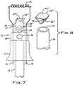
- FIG. 7 is a plan view of an amalgam holder according to still another embodiment of the invention.
- FIG. 8 is a perspective view of a detail of the holder of FIG. 7.
-
- Referring to FIG. 1, an
amalgam holder 10 for a gas discharge lamp such as a fluorescent lamp includes anexhaust tube 12, aflare 14, twolead wires cathode 20 between thelead wires amalgam 22, anextension 24 and a cover orvalve 26. Theexhaust tube 12, theflare 14, theextension 24 may be formed, for example, from glass or a glass-like material. Theleads cathode 20 are electrically conductive materials well-known in the art. Theamalgam 22 is a metallic amalgam of, for example, mercury and other materials known in the art to be suitable for establishing a mercury (or other metallic ion) equilibrium during operation of a discharge lamp. - Typically, the
flare 14 is pinched over theleads exhaust tube 12 while the material of the flare and tube are in a softened state. The area where theflare 14 is pinched is called thepinch 28. Thepinch 28 typically includes avent 30 in communication with the interior of theexhaust tube 12. A discharge lamp typically has a tubular envelope (not shown) that is closed at the end by inserting theflare 14 into the envelope cathode-first and sealing theflare 14 to the envelope. - The
extension 24 can be advantageously formed from an extended portion of thetube 12 or it may be formed as an extension of theflare 14. If desired, theextension 24 could be formed from a separate piece of material. After pinching, there is little apparent difference. - The
extension 24 may be, for example, generally cylindrical with a generallycylindrical cavity 32 within. Theamalgam 22 may be retained within thecavity 32 by adimple 34, or the like, in the wall of theextension 24. Themouth 36 of thecavity 32 may also be narrowed to constrict mercury vapor flow and to allow more efficient covering of themouth 36 with thecover 26. - Referring also to FIG. 2, the
cover 26 is a generally L-shaped piece of bimetal having amounting portion 38 and acover portion 40. Themounting portion 38 is attached to thelead wire 16 by, for example, welding. Thecover portion 40 closes themouth 36 when thecover 26 is cold. During operation of the lamp, thecover 26 is heated and thecover portion 40 lifts off of themouth 36, thereby opening thecavity 32 to the atmosphere inside the envelope. Thecover 26 thus operates as a thermally actuated valve. - When the lamp is at full operating temperature, the
cover 26 has been heated by thecathode 20 and is open and theamalgam 22 establishes a desired mercury equilibrium inside the envelope. When the lamp is turned off, thecover 26 closes off theamalgam 22 from the atmosphere of the envelope thereby preventing the mercury in the envelope atmosphere from recombining with theamalgam 22. In this way, sufficient mercury remains in the envelope atmosphere to prevent mercury starvation during lamp startup. - While the
cover 26 in the preferred embodiment is heat actuated using a bimetallic element, it would also be possible to actuate thecover 26 with electrical, chemical, or other motive techniques. - Referring to FIGS. 3 and 4, an additional embodiment of an amalgam holder 10' includes many of the previously described elements and operates in a similar manner. The bimetal cover 26' includes a mounting portion 38' and a cover portion 40'. The mounting portion 38' is a generally cylindrical sleeve and the cover portion 40' is a flap attached to the mouth end of the sleeve. The extension 24' includes a rolled in
groove 42 to assist in retaining the cover 26' by engaging anannular lip 44 inside the mounting portion 38'. - Similar to the previous embodiment, the cover portion 40' closes the
mouth 36 when the cover 26' is cold. During operation of the lamp, the cover 26' is heated and the cover portion 40' lifts off of themouth 36, thereby opening thecavity 32 to the atmosphere inside the envelope. The cover 26' thus operates as a thermally actuated valve. - Referring to FIGS. 5 and 6, an additional embodiment of an
amalgam holder 10" includes many of the previously described elements and operates in a similar manner. Thebimetal cover 26" includes amounting portion 38", acover portion 40" and astrip portion 46. Themounting portion 38" is a band seated in thegroove 42 and thecover portion 40" is a flap connected to themounting portion 38" by thestrip portion 46. If thestrip portion 46 is considered to be a remaining portion of a cylindrical sleeve, it would represent between 1 and 10 degrees of the sleeve, with 5 degrees being preferred. - Similar to the previous embodiment, the
cover 40" closes themouth 36 when thecover 26" is cold. During operation of the lamp, thecover 26" is heated and thecover portion 40" lifts off of themouth 36, thereby opening thecavity 32 to the atmosphere inside the envelope. Thecover 26" thus operates as a thermally actuated valve. - It should be noted that the embodiments of FIGS. 3, 4, 5 and 6 each have a mounting portion that clasps the extension. While these embodiments completely encircle the extension, it is also possible to clasp the extension with embodiments that do not entirely encircle the extension. For example, if the mounting portion encircles greater than half of the circumference of the extension, the extension will still be clasped by the mounting portion.
- Referring to FIGS 7 and 8, an additional embodiment of an
amalgam holder 10"' includes many of the previously described elements and operates in a similar manner. Thebimetal cover 26"' includes amounting portion 38"' and a cover portion 40'''. The mountingportion 38"' is a V-shaped member that compresses when inserted in themouth 36 and then expands to retain thecover 26"' on theextension 24. The mountingportion 38"' includes anaperture 48 to minimize the blocking of themouth 36 with the mountingportion 38"'. The cover portion 40''' is a flap attached to the top of one leg of the V of the mountingportion 26"'. - Similar to the previous embodiments, the
cover portion 40 closes themouth 36 when thecover 26"' is cold. During operation of the lamp, the cover 26''' is heated and thecover portion 40"' lifts off of themouth 36, thereby opening thecavity 32 to the atmosphere inside the envelope. The cover 26''' thus operates as a thermally actuated valve.
Claims (6)
- An amalgam holder for a discharge lamp having an exhaust tube and a flare pinched about said tube, said holder comprising:an extension of said tube or flare having a cavity for an amalgam, said cavity having a mouth; anda cover for said mouth, said cover being thermally actuated.
- A holder according to claim 1, further comprising a lead wire pinched in said flare, said cover being a bimetallic valve having a mounting portion and a cover portion, said mounting portion being attached to said lead wire and said cover portion movably covering said mouth.
- A holder according to claim 1, wherein said cover comprises a bimetallic valve, said valve having a mounting portion and a cover portion, said mounting portion clasping said extension and said cover portion movably covering said mouth.
- A holder according to claim 3, wherein said mounting portion is a generally cylindrical sleeve about said extension, said sleeve having a mouth end, and said cover portion is a flap attached to said sleeve at said mouth end.
- A holder according to claim 3, wherein said valve further comprises a strip portion and said mounting portion is a band about said extension and said cover portion is a flap, said band being connected to said flap by said strip portion.
- A holder according to claim 1, wherein said cover comprises a bimetallic valve, said valve having a mounting portion and a cover portion, said mounting portion being retained within said extension and said cover portion movably covering said mouth.
Applications Claiming Priority (2)
| Application Number | Priority Date | Filing Date | Title |
|---|---|---|---|
| US584948 | 1990-09-18 | ||
| US09/584,948 US6310437B1 (en) | 2000-06-01 | 2000-06-01 | Fluorescent lamp extension tube amalgam holder |
Publications (1)
| Publication Number | Publication Date |
|---|---|
| EP1160827A1 true EP1160827A1 (en) | 2001-12-05 |
Family
ID=24339414
Family Applications (1)
| Application Number | Title | Priority Date | Filing Date |
|---|---|---|---|
| EP01304803A Withdrawn EP1160827A1 (en) | 2000-06-01 | 2001-05-31 | Fluorescent lamp extension tube amalgam holder |
Country Status (3)
| Country | Link |
|---|---|
| US (1) | US6310437B1 (en) |
| EP (1) | EP1160827A1 (en) |
| JP (1) | JP2002025501A (en) |
Cited By (1)
| Publication number | Priority date | Publication date | Assignee | Title |
|---|---|---|---|---|
| WO2008031764A1 (en) | 2006-09-14 | 2008-03-20 | Osram Gesellschaft mit beschränkter Haftung | Mercury vapor discharge lamp |
Families Citing this family (7)
| Publication number | Priority date | Publication date | Assignee | Title |
|---|---|---|---|---|
| US6456004B1 (en) * | 1999-09-10 | 2002-09-24 | General Electric Company | Fluorescent lamp having uniquely configured container containing amalgam for regulating mercury vapor equilibrium |
| US7095167B2 (en) * | 2003-04-03 | 2006-08-22 | Light Sources, Inc. | Germicidal low pressure mercury vapor discharge lamp with amalgam location permitting high output |
| US7180232B2 (en) * | 2003-06-19 | 2007-02-20 | Koninklijke Philips Electronics, N.V. | Low-pressure mercury vapor discharge lamp |
| CN100568438C (en) * | 2008-03-26 | 2009-12-09 | 汪贤林 | Button silk machine point automatically connects indium net device |
| DE102010031366A1 (en) * | 2010-07-15 | 2012-01-19 | Osram Gesellschaft mit beschränkter Haftung | Pump tube for a gas discharge lamp, method for producing a pump tube for a gas discharge lamp, and method for filling a gas discharge lamp with a gas filling |
| CN102122600A (en) * | 2011-04-03 | 2011-07-13 | 孙向阳 | Low-voltage mercury-free energy-saving bulb |
| DE102011118384A1 (en) * | 2011-11-14 | 2013-05-16 | Heraeus Noblelight Gmbh | Method for manufacturing mercury vapor discharge lamp for generation of optical radiation, involves applying and burning circular rotating gold coating on connecting piece, and providing amalgam depot in tube that is connected with piece |
Citations (13)
| Publication number | Priority date | Publication date | Assignee | Title |
|---|---|---|---|---|
| JPS6056355A (en) * | 1983-09-07 | 1985-04-01 | Matsushita Electronics Corp | Starter built-in type high pressure sodium lamp |
| JPS6056353A (en) * | 1983-09-07 | 1985-04-01 | Matsushita Electronics Corp | Starter built-in type high pressure sodium lamp |
| JPS6147056A (en) * | 1984-08-13 | 1986-03-07 | Toshiba Corp | Fluorescent lamp |
| JPS61232548A (en) * | 1985-04-05 | 1986-10-16 | Matsushita Electric Ind Co Ltd | Low pressure mercury lamp |
| JPS6362144A (en) * | 1986-09-02 | 1988-03-18 | Matsushita Electronics Corp | Electric bulb type fluorescent lamp |
| EP0376399A2 (en) * | 1988-12-30 | 1990-07-04 | North American Philips Corporation | HPS discharge lamp |
| JPH03266352A (en) * | 1990-03-15 | 1991-11-27 | Toshiba Lighting & Technol Corp | Fluorescent lamp |
| JPH03266353A (en) * | 1990-03-15 | 1991-11-27 | Toshiba Lighting & Technol Corp | Fluorescent lamp |
| JPH03285252A (en) * | 1990-03-31 | 1991-12-16 | Toshiba Lighting & Technol Corp | High pressure metallic vapor discharge lamp |
| WO1993011556A1 (en) * | 1991-12-04 | 1993-06-10 | Gte Products Corporation | Mercury vapor discharge lamp containing device for heating amalgam-forming material |
| WO1993011557A1 (en) * | 1991-12-04 | 1993-06-10 | Gte Products Corporation | Low pressure mercury discharge lamp with thermostatic control of mercury vapor pressure |
| JPH0696883A (en) * | 1992-09-14 | 1994-04-08 | Iwasaki Electric Co Ltd | Restarting system for high-pressure sodium lamp |
| EP0809276A1 (en) * | 1996-05-22 | 1997-11-26 | Matsushita Electronics Corporation | Low pressure mercury vapour filled discharge lamp |
Family Cites Families (29)
| Publication number | Priority date | Publication date | Assignee | Title |
|---|---|---|---|---|
| US3619697A (en) | 1964-07-09 | 1971-11-09 | Westinghouse Electric Corp | Mercury vapor discharge lamp and pressure-regulating means therefor |
| US3526804A (en) | 1967-10-27 | 1970-09-01 | Westinghouse Electric Corp | Fluorescent lamp or similar device containing an amalgam of tin-indium-mercury which controls the mercury vapor pressure during operation |
| US3504215A (en) | 1967-11-30 | 1970-03-31 | Westinghouse Electric Corp | Planar fluorescent lamp with integral amalgam type mercury-vapor pressure control component |
| US3526802A (en) | 1968-01-26 | 1970-09-01 | Westinghouse Electric Corp | Compact high-output fluorescent lamp with amalgam type mercury-vapor pressure control means and a neonargon fill gas |
| FR1583078A (en) | 1968-07-15 | 1969-10-17 | ||
| US3591828A (en) | 1968-08-12 | 1971-07-06 | New Nippon Electric Co | Discharge lamp device and its operating apparatus |
| US3562571A (en) | 1969-06-12 | 1971-02-09 | Westinghouse Electric Corp | Mercury-vapor discharge lamp with amalgam-type vapor-pressure regualtor and integral fail-safe and fast warmup compone |
| US3614506A (en) | 1970-04-29 | 1971-10-19 | Westinghouse Electric Corp | Electric discharge lamp having improved mercury-vapor control assembly |
| US3713201A (en) | 1971-05-14 | 1973-01-30 | Westinghouse Electric Corp | Method and apparatus for manufacturing mercury-vapor control assemblies for electric discharge devices |
| US4020378A (en) | 1972-09-28 | 1977-04-26 | Westinghouse Electric Corporation | Integral mercury-vapor pressure regulating means for fluorescent lamp |
| US3898720A (en) | 1972-09-28 | 1975-08-12 | Westinghouse Electric Corp | Method of providing a fluorescent lamp stem with an integral mercury-vapor pressure regulating means |
| DE2330391A1 (en) | 1973-06-14 | 1975-01-09 | Patra Patent Treuhand | LOW PRESSURE MERCURY VAPOR DISCHARGE LAMP WITH AMALGAM |
| DE2339056A1 (en) | 1973-08-01 | 1975-02-13 | Patra Patent Treuhand | LOW PRESSURE MERCURY VAPOR DISCHARGE LAMP WITH AMALGAM |
| DE2510379A1 (en) | 1975-03-10 | 1976-09-30 | Patra Patent Treuhand | LOW PRESSURE MERCURY VAPOR DISCHARGE LAMP WITH AMALGAM |
| US4015162A (en) | 1975-07-07 | 1977-03-29 | Westinghouse Electric Corporation | Fluorescent lamp having implanted amalgamative metal for mercury vapor regulation |
| US4145634A (en) | 1978-02-17 | 1979-03-20 | Westinghouse Electric Corp. | Fluorescent lamp having integral mercury-vapor pressure control means |
| NL183687C (en) * | 1978-10-11 | 1988-12-16 | Philips Nv | LOW-PRESSURE MERCURY DISCHARGE LAMP. |
| US4794301A (en) | 1986-08-19 | 1988-12-27 | Kabushiki Kaisha Toshiba | Fluorescent lamp having a convoluted discharge passage and fluorescent lamp apparatus incorporating the same |
| US5394056A (en) * | 1993-04-07 | 1995-02-28 | General Electric Company | Opening of capsule inside sealed lamp |
| US5598069A (en) | 1993-09-30 | 1997-01-28 | Diablo Research Corporation | Amalgam system for electrodeless discharge lamp |
| DE69403597T2 (en) | 1993-10-04 | 1997-12-18 | Gen Electric | Exact placement and mounting of an amalgam in an electrodeless fluorescent lamp |
| US5434482A (en) | 1993-10-04 | 1995-07-18 | General Electric Company | Electrodeless fluorescent lamp with optimized amalgam positioning |
| US5412288A (en) | 1993-12-15 | 1995-05-02 | General Electric Company | Amalgam support in an electrodeless fluorescent lamp |
| US5412289A (en) | 1993-12-15 | 1995-05-02 | General Electric Company | Using a magnetic field to locate an amalgam in an electrodeless fluorescent lamp |
| US5847508A (en) | 1994-10-03 | 1998-12-08 | General Electric Company | Integrated starting and running amalgam assembly for an electrodeless fluorescent lamp |
| US5739633A (en) | 1995-08-14 | 1998-04-14 | General Electric Company | Amalgam containing compact fluorescent lamp with improved warm-up |
| GB9521375D0 (en) | 1995-10-18 | 1995-12-20 | Gen Electric | Electrodeless fluorescent lamp |
| DE19643219A1 (en) | 1995-10-23 | 1997-04-24 | Gen Electric | Amalgam holder arrangement for an electrodeless discharge lamp |
| US5909085A (en) | 1997-03-17 | 1999-06-01 | Korry Electronics Co. | Hybrid luminosity control system for a fluorescent lamp |
-
2000
- 2000-06-01 US US09/584,948 patent/US6310437B1/en not_active Expired - Fee Related
-
2001
- 2001-05-31 JP JP2001163703A patent/JP2002025501A/en not_active Withdrawn
- 2001-05-31 EP EP01304803A patent/EP1160827A1/en not_active Withdrawn
Patent Citations (13)
| Publication number | Priority date | Publication date | Assignee | Title |
|---|---|---|---|---|
| JPS6056355A (en) * | 1983-09-07 | 1985-04-01 | Matsushita Electronics Corp | Starter built-in type high pressure sodium lamp |
| JPS6056353A (en) * | 1983-09-07 | 1985-04-01 | Matsushita Electronics Corp | Starter built-in type high pressure sodium lamp |
| JPS6147056A (en) * | 1984-08-13 | 1986-03-07 | Toshiba Corp | Fluorescent lamp |
| JPS61232548A (en) * | 1985-04-05 | 1986-10-16 | Matsushita Electric Ind Co Ltd | Low pressure mercury lamp |
| JPS6362144A (en) * | 1986-09-02 | 1988-03-18 | Matsushita Electronics Corp | Electric bulb type fluorescent lamp |
| EP0376399A2 (en) * | 1988-12-30 | 1990-07-04 | North American Philips Corporation | HPS discharge lamp |
| JPH03266352A (en) * | 1990-03-15 | 1991-11-27 | Toshiba Lighting & Technol Corp | Fluorescent lamp |
| JPH03266353A (en) * | 1990-03-15 | 1991-11-27 | Toshiba Lighting & Technol Corp | Fluorescent lamp |
| JPH03285252A (en) * | 1990-03-31 | 1991-12-16 | Toshiba Lighting & Technol Corp | High pressure metallic vapor discharge lamp |
| WO1993011556A1 (en) * | 1991-12-04 | 1993-06-10 | Gte Products Corporation | Mercury vapor discharge lamp containing device for heating amalgam-forming material |
| WO1993011557A1 (en) * | 1991-12-04 | 1993-06-10 | Gte Products Corporation | Low pressure mercury discharge lamp with thermostatic control of mercury vapor pressure |
| JPH0696883A (en) * | 1992-09-14 | 1994-04-08 | Iwasaki Electric Co Ltd | Restarting system for high-pressure sodium lamp |
| EP0809276A1 (en) * | 1996-05-22 | 1997-11-26 | Matsushita Electronics Corporation | Low pressure mercury vapour filled discharge lamp |
Non-Patent Citations (5)
| Title |
|---|
| PATENT ABSTRACTS OF JAPAN vol. 009, no. 189 (E - 333) 6 August 1985 (1985-08-06) * |
| PATENT ABSTRACTS OF JAPAN vol. 012, no. 285 (E - 642) 4 August 1988 (1988-08-04) * |
| PATENT ABSTRACTS OF JAPAN vol. 016, no. 074 (E - 1170) 24 February 1992 (1992-02-24) * |
| PATENT ABSTRACTS OF JAPAN vol. 016, no. 112 (E - 1180) 19 March 1992 (1992-03-19) * |
| PATENT ABSTRACTS OF JAPAN vol. 018, no. 355 (E - 1573) 5 July 1994 (1994-07-05) * |
Cited By (2)
| Publication number | Priority date | Publication date | Assignee | Title |
|---|---|---|---|---|
| WO2008031764A1 (en) | 2006-09-14 | 2008-03-20 | Osram Gesellschaft mit beschränkter Haftung | Mercury vapor discharge lamp |
| CN101517688B (en) * | 2006-09-14 | 2012-01-11 | 奥斯兰姆有限公司 | Mercury vapor discharge lamp |
Also Published As
| Publication number | Publication date |
|---|---|
| US6310437B1 (en) | 2001-10-30 |
| JP2002025501A (en) | 2002-01-25 |
Similar Documents
| Publication | Publication Date | Title |
|---|---|---|
| US5274305A (en) | Low pressure mercury discharge lamp with thermostatic control of mercury vapor pressure | |
| US6310437B1 (en) | Fluorescent lamp extension tube amalgam holder | |
| US4013919A (en) | Discharge lamp having fuse-switch guard against jacket failure | |
| KR900006200B1 (en) | Flueoroscent lamp | |
| US5757137A (en) | High pressure sodium lamp with bimetallic starting aid and ignition wire | |
| JP2000508827A (en) | Electrodeless low pressure mercury discharge lamp | |
| EP0910111A3 (en) | Miniature projection lamp | |
| CA2214660A1 (en) | Starting flag structure for tubular low pressure discharge lamps | |
| US6456004B1 (en) | Fluorescent lamp having uniquely configured container containing amalgam for regulating mercury vapor equilibrium | |
| US5237240A (en) | Mercury vapor discharge lamp containing device for heating amalgam-forming material | |
| CA1182509A (en) | Starting aid for high pressure sodium vapor lamp | |
| JP2002538583A (en) | Low pressure mercury vapor discharge lamp | |
| JP2002515167A (en) | Reflective lamp | |
| EP1538661A3 (en) | A metal halide lamp | |
| HU193458B (en) | High-pressure discharge lamp with at least two discharge tube | |
| US6707246B1 (en) | Low-pressure mercury vapor discharge lamp with improved auxiliary amalgam | |
| JP3687779B2 (en) | Fluorescent lamp | |
| EP0159009B1 (en) | Circuit breaker with thin-walled bulb | |
| US4659966A (en) | Rapid-start fluorescent lamp integrated circuit breaker structure and manufacture | |
| US4442379A (en) | High pressure sodium vapor lamp having resistance heater means | |
| US4459513A (en) | High pressure sodium vapor lamp having resistance heater means | |
| CA2395000A1 (en) | Amalgam retainer | |
| US4442378A (en) | High pressure sodium vapor lamp having resistance heater means | |
| JPH1050255A (en) | Discharge lamp and manufacture of cathode assembly for discharge lamp | |
| JPS6362144A (en) | Electric bulb type fluorescent lamp |
Legal Events
| Date | Code | Title | Description |
|---|---|---|---|
| PUAI | Public reference made under article 153(3) epc to a published international application that has entered the european phase |
Free format text: ORIGINAL CODE: 0009012 |
|
| AK | Designated contracting states |
Kind code of ref document: A1 Designated state(s): DE FR GB IT Kind code of ref document: A1 Designated state(s): AT BE CH CY DE DK ES FI FR GB GR IE IT LI LU MC NL PT SE TR |
|
| AX | Request for extension of the european patent |
Free format text: AL;LT;LV;MK;RO;SI |
|
| 17P | Request for examination filed |
Effective date: 20020605 |
|
| AKX | Designation fees paid |
Free format text: DE FR GB IT |
|
| 17Q | First examination report despatched |
Effective date: 20081126 |
|
| STAA | Information on the status of an ep patent application or granted ep patent |
Free format text: STATUS: THE APPLICATION IS DEEMED TO BE WITHDRAWN |
|
| 18D | Application deemed to be withdrawn |
Effective date: 20090609 |