EP1160788A2 - Disk apparatus and disk medium - Google Patents
Disk apparatus and disk medium Download PDFInfo
- Publication number
- EP1160788A2 EP1160788A2 EP00311394A EP00311394A EP1160788A2 EP 1160788 A2 EP1160788 A2 EP 1160788A2 EP 00311394 A EP00311394 A EP 00311394A EP 00311394 A EP00311394 A EP 00311394A EP 1160788 A2 EP1160788 A2 EP 1160788A2
- Authority
- EP
- European Patent Office
- Prior art keywords
- servo
- information
- written
- servo information
- landing area
- Prior art date
- Legal status (The legal status is an assumption and is not a legal conclusion. Google has not performed a legal analysis and makes no representation as to the accuracy of the status listed.)
- Granted
Links
Images




Classifications
-
- G—PHYSICS
- G11—INFORMATION STORAGE
- G11B—INFORMATION STORAGE BASED ON RELATIVE MOVEMENT BETWEEN RECORD CARRIER AND TRANSDUCER
- G11B5/00—Recording by magnetisation or demagnetisation of a record carrier; Reproducing by magnetic means; Record carriers therefor
- G11B5/48—Disposition or mounting of heads or head supports relative to record carriers ; arrangements of heads, e.g. for scanning the record carrier to increase the relative speed
- G11B5/54—Disposition or mounting of heads or head supports relative to record carriers ; arrangements of heads, e.g. for scanning the record carrier to increase the relative speed with provision for moving the head into or out of its operative position or across tracks
-
- G—PHYSICS
- G11—INFORMATION STORAGE
- G11B—INFORMATION STORAGE BASED ON RELATIVE MOVEMENT BETWEEN RECORD CARRIER AND TRANSDUCER
- G11B21/00—Head arrangements not specific to the method of recording or reproducing
- G11B21/02—Driving or moving of heads
- G11B21/12—Raising and lowering; Back-spacing or forward-spacing along track; Returning to starting position otherwise than during transducing operation
-
- G—PHYSICS
- G11—INFORMATION STORAGE
- G11B—INFORMATION STORAGE BASED ON RELATIVE MOVEMENT BETWEEN RECORD CARRIER AND TRANSDUCER
- G11B5/00—Recording by magnetisation or demagnetisation of a record carrier; Reproducing by magnetic means; Record carriers therefor
- G11B5/48—Disposition or mounting of heads or head supports relative to record carriers ; arrangements of heads, e.g. for scanning the record carrier to increase the relative speed
- G11B5/58—Disposition or mounting of heads or head supports relative to record carriers ; arrangements of heads, e.g. for scanning the record carrier to increase the relative speed with provision for moving the head for the purpose of maintaining alignment of the head relative to the record carrier during transducing operation, e.g. to compensate for surface irregularities of the latter or for track following
- G11B5/596—Disposition or mounting of heads or head supports relative to record carriers ; arrangements of heads, e.g. for scanning the record carrier to increase the relative speed with provision for moving the head for the purpose of maintaining alignment of the head relative to the record carrier during transducing operation, e.g. to compensate for surface irregularities of the latter or for track following for track following on disks
- G11B5/59688—Servo signal format patterns or signal processing thereof, e.g. dual, tri, quad, burst signal patterns
-
- G—PHYSICS
- G11—INFORMATION STORAGE
- G11B—INFORMATION STORAGE BASED ON RELATIVE MOVEMENT BETWEEN RECORD CARRIER AND TRANSDUCER
- G11B2220/00—Record carriers by type
- G11B2220/20—Disc-shaped record carriers
- G11B2220/25—Disc-shaped record carriers characterised in that the disc is based on a specific recording technology
- G11B2220/2508—Magnetic discs
- G11B2220/2516—Hard disks
Definitions
- a ramp loading mechanism is provided to: move a head to a ramp from a host in an access waiting mode, a drive current of a voice coil motor (hereinafter, abbreviated to "VCM”) is shut off; and the apparatus is set into the access waiting mode, thereby suppressing a VCM current consumption in the access waiting mode and extending a life of a battery of a notebook-sized personal computer or the like having the disk apparatus therein.
- VCM voice coil motor
- a gain control operation of an AGC amplifier provided in a read channel and an adjustment of synchronization for a read clock of a PLL is necessary at the time of servo lead-in. Both of them are performed by using a head preamble of servo information. Particularly, in recent years, since the servo information is also sampled by an A/D converter and processed, it is necessary to detect the servo information a number of times. The number of times the servo information is recorded on the medium per circumference has been predetermined. It is preferable to set the number of times the servo information is recorded to a small value in consideration of an efficiency of a data format.
- the lead-in of the servo detecting system can be completed in the landing area. Although it is necessary to sample the servo information a number of times for the purpose of lead-in of the servo detecting system, since the second servo information in the landing area has been written at the finer interval than that of the first servo information in the data area, the servo information can be sampled the necessary number of times in a short time. The time necessary for the control of a proper value in the AGC of a variable gain control amplifier (VGC) and the adjustment of a proper value in the PLL is remarkably reduced.
- VGC variable gain control amplifier
- the second servo information in the landing area has a servo pattern to which position information which can discriminate the position in the circumferential direction.
- This information is written in the same servo pattern as that of the first servo information in the data area.
- a servo pattern to which the position information which can discriminate the position in the circumferential direction has been added is written as second servo information in the landing area into a Gray code of the first servo information.
- the position information of the second servo information is written as either the position in the circumferential direction between sectors based on the first servo information or the position in the circumferential direction from index servo information on the medium.
- the lead-in control unit Upon completion of the lead-in of the servo detecting system based on the second servo information, the lead-in control unit obtains a deviation time for the first servo information on the basis of the position information of the second servo information and changes the timing for turning on a subsequent servo gate signal SG by the deviation time, thereby synchronizing it with the first servo information. If the lead-in of the servo detecting system is completed by the sampling of the first servo information in the landing area, there is no need to change the lead-in timing, since this means that the synchronization has already been established. This is advantageous where the first and second servo information co-exist in the landing area.
- the second servo information in the landing area has a servo pattern, to which the position information which can discriminate the position in the circumferential direction has been added, which can be different from the first servo information, for example: a servo pattern obtained by excluding burst information from the first servo information; a servo pattern obtained by excluding cylinder information from the first servo information; a servo pattern comprising a preamble and servo mark information; or a servo pattern comprising only the preamble is used as second servo information.
- a second aspect of the invention provides a disk medium which is used for the disk apparatus having the ramp loading mechanism and is characterized in that the servo information has been written in the landing area on the medium. That is, it is characterized in that the second servo information is written in the landing area on the medium at the finer interval than that of the first servo information written in the data area.
- the details of the disk medium are fundamentally the same as those as specified above in the case of the apparatus.
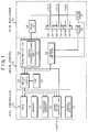
- Fig. 1 is a block diagram of a hard disk drive to which the invention is applied.
- the hard disk drive comprises an SCSI controller 10, a drive control 12, and a disk enclosure 14.
- An interface with a host is not limited to the SCSI controller 10 any any suitable interface controller can be used.
- the SCSI controller 10 has: an MCU (main control unit) 16; a flash memory 18 which is used as a control storage; a program memory 20 in which a control program has been stored; a hard disk controller (HDC) 22; and a data buffer 24.
- the drive control 12 has: a drive interface logic 26; a DSP 28; a read/write LSI 30 which has a servo demodulating unit 32 and functions as a read channel (RDC); and a servo driver 34.
- the disk enclosure 14 has a head IC 36.
- Combination heads 38-1 to 38-6 each having a write head and a read head are connected to the head IC 36.
- the combination heads 38-1 to 38-6 are supported to a tip of an arm of a rotary actuator, provided for respective recording surfaces of disks 40-1 to 40-3, and moved to arbitrary track positions on the disks 40-1 to 40-3 by the driving of the rotary actuator by a VCM 44.
- a ramp loading mechanism is provided on a head moving locus on the opposite side of the disks 40-1 to 40-3.
- the unloading operation such that the combination heads 38-1 to 38-6 are moved to positions over the ramps and stop at the time of activation of the hard disk drive or during the access waiting mode from the host is performed.
- the loading operation is started, the combination heads 38-1 to 38-6 are moved from the ramps to the landing area toward the maximum values of the disks 40-1 to 40-3 by a speed control of the VCM 44, and a servo lead-in is performed.
- the head is positioned to a target position by a command from the host upon completion of the servo lead-in.
- the disks 40-1 to 40-3 are rotated at a constant velocity by a spindle motor 42.
- the operation of the hard disk drive is executed as follows. For example, a case where the write command is issued from the host will be explained.
- the write command is stored in a command queue in the flash memory through the hard disk controller 22.
- the MCU 16 extracts the write command from the head position of the command queue in the flash memory 18 and requests the host to transfer the write command by using the hard disk controller 22.
- the write command transferred from the host is stored in the data buffer 24.
- the MCU 16 activates the hard disk controller 22 and writes the write data to the disks 40-1 to 40-3.
- the write data stored in the data buffer 24 is written on a sector position of a track designated by the write command by using the write head provided for, for example, the combination head 38-1 through the writing system comprising the hard disk controller 22, drive interface logic 26, and read/write LSI 30 and via the head IC 36.
- the DSP 28 controls the positioning operation of the head by the VCM 44 to the track position designated by the write command, namely, controls the servo driver 34 by a servo demodulation signal obtained through the servo demodulating unit 32 and executes the writing operation of the write data to the disk when the combination head 38-1 is positioned to the target sector designated by the write command.
- the MCU 16 When such a writing operation is finished, the MCU 16 notifies the host of a status indicative of the normal end of the write command through the hard disk controller 22.
- the MCU 16 extracts the read command and reproduces the data written at the sector position of the track, designated by the read command, by using the read head provided for, for instance, the combination head 38-1 through the reading system comprising the hard disk controller 22, drive interface logic 26, and read/write LSI 30 and via the head IC 36.
- the MCU 16 transfers the read-out data to the host. Further, in the access waiting mode in which the write command or read command is not issued from the host, the MCU 16 instructs the DSP 28 to execute an unloading process for unloading the head from the ramp loading mechanism.
- the DSP 28 When the command is received from the host in the unloading state where the heads are positioned and stopped at the ramp loading mechanisms as mentioned above, the DSP 28 first performs a ramp loading control for moving the head from the ramp over the disk on the basis of the instruction of the MCU 16 and executes a servo lead-in for properly making adjustments of the AGC and PLL of the variable gain amplifier (VGA) provided for the read/write LSI 30, during the movement of the head in the landing area on the disk. When the head is moved from the landing area to the data area in which data can be read/written, the DSP 28 performs a seek control for moving the laser beam toward the target sector designated by the command so as to enter an on-track state and, thereafter, positions the head to the sector position.
- VGA variable gain amplifier
- a head speed signal is detected from a counter electromotive voltage (induced e.m.f.) of the VCM 44 and a ramp speed control of, for example, a speed which is equal to or smaller than 1/10 of a head speed at the time of the seek control is executed.
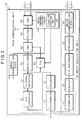
- Fig. 2 is a block diagram of the read/write LSI 30 in Fig. 1, which provides what is usually known as a read channel.
- the read/write LSI 30 is constructed by the servo demodulating unit 32, a write modulating unit 56, and a read demodulating unit 58.
- the write modulating unit 56 is constructed by a scrambler 46, an encoder 48, a parallel/serial (P/S) converter 50, a precoder 52, and a write compensating circuit 54.
- P/S parallel/serial
- the write data formatted by the hard disk controller 22 in Fig. 1 is received and first subjected to a scrambling process on the basis of the EX-OR with a pseudo random pattern by the scrambler 46.
- the scrambler 46 scrambles the portions of the data bytes and the ECC. Subsequently, the scrambled data is converted into, for example, an 8/9 code by the RLL encoder 48. For example, the byte data so far is subsequently converted into serial data by the P/S converter 50.
- the read demodulating unit 58 is constructed by: a variable gain amplifier (VGA) 60 for performing an AGC control; a filter 62; an A/D converter 64; an equalizer 66; a PLL 68 having a VFO (variable frequency oscillator) therein; a Viterbi detector 70; a serial/ parallel (S/P) converter 72; an RLL decoder 74; a descrambler 76; and read channel control logic 78.
- VGA variable gain amplifier
- the operation of the read demodulating unit 58 is as follows.
- An analog read signal generated from the head is amplified by the VGA 60 on the basis of an automatic gain control (AGC), and thereafter, band controlled in accordance with low pass characteristics of the filter 62, and converted into digital read data by the A/D converter 64 on the basis of a sampling clock from the PLL 68.
- the equalizer 66 performs an equalization of (1 + D) to the read data.
- the read data is demodulated by the Viterbi detector 70 in accordance with a Viterbi algorithm.
- the PLL 68 controls a frequency of the sampling clock to the A/D converter 64 synchronously with the read data equalized in the equalizer 66.
- the read data demodulated by the Viterbi detector 70 is converted into parallel data in units of, for example, a byte by the S/P converter 72, subjected to an 8/9 inverse conversion by the RLL decoder 74, and further, descrambled with respect to an ECC portion of the data bytes by the descrambler 76 by using a pseudo random code.
- the demodulated read data is outputted to the hard disk controller 22 in Fig. 1 and transferred to a higher-level apparatus through the data buffer 24.
- the read channel control logic 78 receives a control signal from the hard disk controller 22 in Fig.1 and performs a lead-in control at the time of loading the head from the ramp loading mechanism to the landing area on the disk; controls the reading operation based on a read gate signal RG from the hard disk controller 22; controls the writing operation based on a write gate signal WG; and further controls the servo demodulating operation based on a servo gate signal SG for deciding a servo interruption timing.
- Fig. 3 is an explanatory diagram of the ramp loading mechanism which is used in the hard disk drive of the invention.
- a ramp 82 is provided on a locus of the head which is moved by the rotary actuator outside of the disk 40-1.
- an inclined path 82-3 is formed leading to a landing area 84 in an outer peripheral portion of the disk 40-1, subsequently, a horizontal path 82-2 is formed on the outer side, and a stop portion 82-1 for stopping and holding the head is formed outside of the horizontal path 82-2.
- the head is stopped at a position where it is pressed to the outer side of the stop portion 82-1 in the unloaded state.
- the head In response to receiving a command from the host for loading to the disk 40-1, the head is moved from the stop portion 82-1 toward the disk 40-1 side while performing a speed control by supplying an inner ejection current to the VCM.
- the head passes from the horizontal path 82-2 to the inclined path 82-3 and is loaded by lowering it onto the landing area 84 on the disk 40-1.
- the servo lead-in is performed for adjustment of the proper values in the AGC and PLL.
- a position control is performed to the sector position on the track designated by the command.
- Fig. 4 is a plan view of the disk 40-1 in Fig. 3 and shows a half thereof.
- the disk 40-1 has a data area 86 for recording/reproducing data to/from the inside of the outer peripheral landing area 84.
- First servo patterns 88 are written in the data area 86 so as to be divided in the circumferential direction.
- the first servo pattern 88 is expressed as an area which extends as a bold line from the center in the radial direction. In the embodiment, the first servo patterns 88 extend to the landing area.
- Second servo patterns 90 are written between the first servo patterns 88 within the landing area 84 so as to be arranged at a finer interval than that in the circumferential direction of the first servo pattern 88.
- Figs. 5A to 5C are enlarged diagrams of the first servo patterns 88 and second servo patterns 90 written in the landing area 84 in Fig. 4.
- Fig. 5A shows the servo patterns in the landing area 84.
- the second servo patterns 90 are provided at a finer interval in the area between the first servo patterns 88 recorded in the radial direction from the data area shown by the bold line.
- a plurality of patterns are written between the first servo patterns 88 so that an area therebetween is completely filled with the second servo patterns.
- the second servo patterns 90 are written between the first servo patterns 88 over the whole circumference of the landing area 84.
- a servo format of the second servo pattern as representatively illustrated by a second servo pattern 90-i in Fig. 5C, there are sequentially written: a preamble 92; a servo mark 94; a Gray code 96 indicative of a cylinder address; a burst 98 in which four kinds of burst patterns A, B, C, and D obtained as a double-phase servo have been written; a pad 99; and further, position information 100 showing the position in the circumferential direction of the second servo pattern 90-i between the sectors serving as an area between the first servo patterns 88.
- the format from the preamble 92 to the pad 99 in the second servo pattern 90-i is the same servo format as that of the first servo patterns 88 radially recorded from the data area to the landing area 84.
- the position information 100 is added to the same servo format as that of the first servo pattern 88.
- the position information 100 is used for obtaining the deviation time for the first servo pattern 88, changing the subsequent lead-in timing by the deviation time, and synchronizing it with the lead-in timing of the first servo pattern 88.
- Figs. 6A to 6D are diagrams for explaining the servo lead-in operation in the landing area in an embodiment of the invention.
- Fig. 6A shows the servo pattern of the landing area 84.
- Fig. 6A shows an example in the case where, for instance, ten second servo patterns 90-1 to 90-10 have been written between first servo patterns 88-1 and 88-2.
- An interval between the head of the first servo pattern 88-1 and the head of the next first servo pattern 88-2 is an ordinary servo interval 118 on the data surface.
- the servo interval 118 is shown by the number of fundamental clocks which are used for the servo control.
- the number of clocks of the deviation time Td for the next first servo pattern 88-2 can be calculated by subtracting the number of clocks of the position information in the circumferential direction of the second servo pattern 90-4 at the lead-in completion position 122 from the number of clocks of the ordinary servo interval 118.
- the deviation time Td regarding the second servo pattern 90-4 at the lead-in completion position 122 can be calculated as mentioned above, by deviating a servo interruption timing (timing for turning on the servo gate signal SG) by the deviation time Td, the servo interruption timing can be matched with the first servo pattern 88-2 common to the data area after completion of the servo lead-in based on the second servo pattern 90-4 as shown in Fig. 6D. After that, even in the landing area 84, the servo interruption timing can be synchronized with the first servo patterns 88-1, 88-2, ... sequel to the data area.
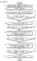
- Fig. 7 is a flowchart for a ramp loading process of the invention according to the lead-in control unit 80 provided for the read channel control logic 78 in Fig. 2.
- step S1 the ramp loading operation is started on the basis of the reception of the host command.
- the head is moved from the ramp 82 to the landing area 84 on the disk 40-1 by controlling the speed.
- the landing is started in step S2.
- step S2 When the head is moved to the landing area 84, since the second servo patterns 90 have been written in the landing area 84 on the whole circumference so as to fill the area between the first servo patterns 88 from the data area 86 as shown in Fig.
- a head output level is measured in step S3 with respect to a head output by the reading of the first servo patterns 88 and second servo patterns 90. Whether the head output level is a detectable level or not is determined in step S4.
- the servo lead-in is started in step S5.
- the proper adjustments of the AGC and PLL are made by using the read signal of the preamble 92 in Fig. 5C locating at the head of each servo signal.
- step S5 By the start of the servo lead-in in step S5, the servo lead-in using the preambles 92 of the continuous second servo patterns is repeated.
- step S6 the completion of the servo lead-in is decided in step S6 and step S7 follows.
- step S7 with respect to the second servo patterns 90 by which the servo lead-in has been completed, on the basis of the position information 100 in the circumferential direction written after the servo pattern as shown in Fig. 5C, a process for detecting the position error from the data area servo sector, namely, the deviation time from the next first servo pattern as shown in Fig. 6C is started.
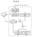
- An adjustment value in the register 130 is stored as a final adjustment value in the final adjustment value setting device 136.
- the change-over switch 126 has been switched to the side of the adjustment initial value setting device 125.
- the switch 126 is switched to the side of the final adjustment value setting device 136.
- the change-over switch 128 is switched to the side of the change-over switch 126 at the start of the servo lead-in, thereby allowing the adjustment initial value or previous adjustment initial value to be fetched in the register 130.
- the switch 128 is switched to the side of the discriminating unit 135.
- the gain control value obtained from the discriminating unit 135 is fetched during the adjustment and the gain of the VGA 60 is controlled so that an amplitude is set to a proper value.
- An amplitude detector 132 detects an amplitude of the servo read signal obtained from the VGA 60, compares it with the proper value from the discriminating unit 135, and obtains the next gain control value.
- An output of the VGA 60 is also supplied to a Gray code/servo mark detector 134.
- the Gray code/servo mark detector 134 the position information 100 in the circumferential direction provided at the end of the second servo pattern 90-i in Fig. 5C can be detected. That is, since position information 100 is written in the circumferential direction of the second servo pattern, it can be detected by the Gray code/servo mark detector 134.
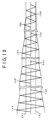
- the process for changing the adjustment value for the register 130 is continued until a reaching signal point 150 where no preamble is obtained, this means that the proper amplitude values 160 and 162 by the amplitude detector 132 and discriminating unit 135 by using the previous final adjustment value as an initial value can be determined. This point is also similarly applied to an interval between signal points 152 and 154. Such a process is repeated each time the preamble of the servo pattern is obtained. As soon as the amplitude of the VGA 60 is finally adjusted to the required values 160 and 162 at a signal point 158 by the adjustment from a signal point 156, the lead-in of the servo detecting system is deemed to be completed.
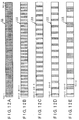
- Fig. 12A a second servo pattern arrangement 104 in Fig. 12C, the second servo patterns 90-2, 90-5, ... are written in every third place between the sectors. Further, in a second servo pattern arrangement 106 in Fig. 12D, the second servo patterns 90-2, 90-6, ... are written in every fourth place between the sectors.
- Fig. 12E after the second servo pattern 90-2 was written between the sectors, the next three second servo patterns 90-6 to 90-8 are recorded while three spaces are held between the pattern 90-2 and pattern 90-6. After that, the writing of one second servo pattern and three second servo patterns is similarly repeated while three spaces are held.
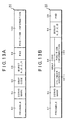
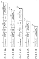
- a second servo pattern 116 in Fig. 14E is constructed by only the preamble 92 and position information 100.
- the second servo patterns 90, 110, 112, 114, and 116 by providing the preamble 92 at the head of the servo pattern and providing the position information 100 in the circumferential direction showing the position between the sectors, it is possible to realize the change to the servo interruption timing synchronized with the first servo pattern in the data area at a time point of the completion of the servo lead-in by an arbitrary second servo pattern.
- the head When the head is moved to the landing area, even if the head has come into contact with the medium and the servo information is consequently missing, since the servo information has been written in the circumferential direction of the landing area, for example, over the whole circumference, even if the servo information is missed initially, the servo information can be subsequently obtained at a short sampling interval. Therefore, no trouble is caused in the servo lead-in operation and the servo lead-in can be completed in a short time.
Landscapes
- Engineering & Computer Science (AREA)
- Signal Processing (AREA)
- Moving Of The Head To Find And Align With The Track (AREA)
- Moving Of Heads (AREA)
- Signal Processing For Digital Recording And Reproducing (AREA)
Abstract
Description
Claims (20)
- A disk apparatus having a ramp loading mechanism, comprising:a disk medium in which servo information has been written in a landing area on the medium; anda lead-in processing unit which performs a servo lead-in on the basis of said servo information when a head is moved from a ramp to said landing area on said medium.
- An apparatus according to claim 1, wherein on said disk medium, second servo information has been written in said landing area at a finer interval than that of first servo information as that written in a data area.
- An apparatus according to claim 1, wherein on said disk medium, said second servo information has been written in said landing area at a finer interval in addition to same first servo information written in a data area.
- An apparatus according to claim 1, wherein on said disk medium, said servo information has been written in said landing area over a whole circumference.
- An apparatus according to claim 1, wherein on said disk medium, as said servo information in said landing area, second servo information having a servo pattern to which position information which can discriminate a position in the circumferential direction was added has been written on a same servo pattern as that of first servo information in said data area.
- An apparatus according to claim 1, wherein on said disk medium, as said servo information in said landing area, second servo information having a servo pattern to which position information which can discriminate a position in the circumferential direction was added has been written on a Gray code of a same servo pattern as that of first servo information in said data area.
- An apparatus according to claim 5, wherein the position in the circumferential direction between sectors by said first servo information has been written as said position information of said second servo information.
- An apparatus according to claim 5, wherein the position in the circumferential direction from index servo information on the medium has been written as said position information of said second servo information.
- An apparatus according to claim 5, wherein upon completion of a lead-in based on said second servo information, said lead-in processing unit obtains a deviation time for said first servo information on the basis of said position information of said second servo information and changes a subsequent servo interruption timing by said deviation time, thereby synchronizing said timing with the first servo information.
- An apparatus according to claim 1, wherein on said disk medium, as said servo information in said landing area, second servo information having a servo pattern to which position information which can discriminate a position in the circumferential direction was added has been written on a servo pattern different from that of first servo information in a data area.
- An apparatus according to claim 10, wherein as said servo pattern of said second servo information different from that of said first servo information, a servo pattern obtained by excluding burst information from said first servo information is used.
- An apparatus according to claim 10, wherein as said servo pattern of said second servo information different from that of said first servo information, a servo pattern obtained by excluding cylinder information from said first servo information is used.
- An apparatus according to claim 10, wherein as said servo pattern of said second servo information different from that of said first servo information, a servo pattern comprising a preamble and servo mark information is used.
- An apparatus according to claim 10, wherein as said servo pattern of said second servo information different from that of said first servo information, a servo pattern comprising only a preamble is used.
- A disk medium which is used for a disk apparatus having a ramp loading mechanism, wherein servo information has been written in a landing area on the medium.
- A medium according to claim 15, wherein second servo information has been written in said landing area at a finer interval in addition to first servo information written in a data area.
- A medium according to claim 15, wherein second servo information has been written in said landing area at a finer interval in addition to same first servo information as that in a data area.
- A medium according to claim 15, wherein said servo information has been written in said landing area over a whole circumference.
- A medium according to claim 15, wherein as said servo information in said landing area, second servo information having a servo pattern to which position information which can discriminate a position in the circumferential direction was added has been written in first servo information in said data area.
- A medium according to claim 15, wherein as said servo information in said landing area, second servo information having a servo pattern to which position information which can discriminate a position in the circumferential direction was added has been written in a servo pattern different from that of first servo in formation in said data area.
Applications Claiming Priority (2)
| Application Number | Priority Date | Filing Date | Title |
|---|---|---|---|
| JP2000164095A JP3757098B2 (en) | 2000-06-01 | 2000-06-01 | Disk device and disk medium |
| JP2000164095 | 2000-06-01 |
Publications (3)
| Publication Number | Publication Date |
|---|---|
| EP1160788A2 true EP1160788A2 (en) | 2001-12-05 |
| EP1160788A3 EP1160788A3 (en) | 2002-10-30 |
| EP1160788B1 EP1160788B1 (en) | 2004-08-04 |
Family
ID=18667758
Family Applications (1)
| Application Number | Title | Priority Date | Filing Date |
|---|---|---|---|
| EP00311394A Expired - Lifetime EP1160788B1 (en) | 2000-06-01 | 2000-12-19 | Disk apparatus and disk medium |
Country Status (5)
| Country | Link |
|---|---|
| US (1) | US6504663B2 (en) |
| EP (1) | EP1160788B1 (en) |
| JP (1) | JP3757098B2 (en) |
| KR (1) | KR100634106B1 (en) |
| DE (1) | DE60012708T2 (en) |
Families Citing this family (29)
| Publication number | Priority date | Publication date | Assignee | Title |
|---|---|---|---|---|
| JP2000339891A (en) * | 1999-05-31 | 2000-12-08 | Sony Corp | Recording and / or playback device |
| US6661597B1 (en) * | 2001-04-30 | 2003-12-09 | Western Digital Technologies, Inc. | Mobile device and disk drive restricted from writing a data storage zone in a mobile environment |
| JP2002367308A (en) * | 2001-06-06 | 2002-12-20 | Hitachi Ltd | Magnetic disk drive and servo write method |
| JP2003141839A (en) * | 2001-11-01 | 2003-05-16 | Hitachi Ltd | Load / unload method and magnetic disk drive using the same |
| US7006315B2 (en) * | 2002-12-27 | 2006-02-28 | Matsushita Electric Industrial Co., Ltd. | Systems for improving servo-demodulation robustness |
| US7006312B2 (en) * | 2002-12-27 | 2006-02-28 | Matsushita Electic Industrial Co., Ltd. | Methods for preventing channel control values from being corrupted to thereby improve servo-demodulation robustness |
| US6943981B2 (en) * | 2002-12-27 | 2005-09-13 | Matsushita Electric Co., Ltd. | Methods for improving servo-demodulation robustness |
| US7006311B2 (en) * | 2002-12-27 | 2006-02-28 | Matsushita Electric Industrial Co., Ltd | Systems for preventing channel control values from being corrupted to thereby improve servo-demodulation robustness |
| US7016133B2 (en) * | 2002-12-27 | 2006-03-21 | Matsushita Electric Industrial Co., Ltd. | Systems for detecting multiple occurrences of a SAM pattern to thereby improve servo-demodulation robustness |
| US6995935B2 (en) * | 2002-12-27 | 2006-02-07 | Matsushita Electric Industrial Co., Ltd. | Methods for detecting multiple occurrences of a SAM pattern to thereby improve servo-demodulation robustness |
| US7092177B2 (en) * | 2003-07-16 | 2006-08-15 | Matsushita Electric Industrial Co., Ltd. | Methods for searching for SAM patterns using multiple sets of servo demodulation detection parameters |
| US7072128B2 (en) * | 2003-07-16 | 2006-07-04 | Matsushita Electric Industrial Co., Ltd. | Methods for searching for SAM patterns at multiple nominal frequencies |
| US7075742B2 (en) * | 2003-07-16 | 2006-07-11 | Matsushita Electric Industrial Co., Ltd. | Servo demodulator systems including multiple servo demodulators |
| US7054083B2 (en) * | 2003-07-16 | 2006-05-30 | Matsushita Electric Industrial Co., Ltd. | Systems for searching for SAM patterns at multiple nominal frequencies |
| US6992855B2 (en) * | 2003-09-18 | 2006-01-31 | Matsushita Electric Industrial Co., Ltd. | Methods for limiting channel control values to thereby improve servo-demodulation robustness |
| US6992856B2 (en) * | 2003-09-18 | 2006-01-31 | Matsushita Electric Industrial Co., Ltd. | Systems for limiting channel control values to thereby improve servo-demodulation robustness |
| KR100559730B1 (en) | 2003-09-22 | 2006-03-15 | 삼성전자주식회사 | Method and apparatus for data encoding / decoding for recording system |
| US7392530B2 (en) * | 2004-01-09 | 2008-06-24 | Hiro 21 Corporation | Disk drive device, disk drive system and disk |
| JP4074262B2 (en) * | 2004-03-31 | 2008-04-09 | 株式会社東芝 | Magnetic recording medium, manufacturing method thereof, and magnetic recording / reproducing apparatus |
| US7154698B2 (en) * | 2004-09-30 | 2006-12-26 | Hitachi Global Storage Technologies Netherlands B.V. | Load/unload system and method for maximizing disk writeable area |
| JP2006294092A (en) * | 2005-04-07 | 2006-10-26 | Hitachi Global Storage Technologies Netherlands Bv | Magnetic disk device and magnetic disk medium |
| JP4649262B2 (en) * | 2005-04-19 | 2011-03-09 | 株式会社東芝 | Method for manufacturing magnetic recording medium |
| US7209310B1 (en) * | 2005-07-25 | 2007-04-24 | Western Digital Technologies, Inc. | Disk drive identifying starting track by performing multiple load operations |
| JP4585476B2 (en) | 2006-03-16 | 2010-11-24 | 株式会社東芝 | Patterned medium and magnetic recording apparatus |
| JP4675812B2 (en) * | 2006-03-30 | 2011-04-27 | 株式会社東芝 | Magnetic recording medium, magnetic recording apparatus, and method of manufacturing magnetic recording medium |
| JP2008282512A (en) | 2007-05-14 | 2008-11-20 | Toshiba Corp | Magnetic recording medium and magnetic recording / reproducing apparatus |
| JP4382843B2 (en) | 2007-09-26 | 2009-12-16 | 株式会社東芝 | Magnetic recording medium and method for manufacturing the same |
| US9971606B2 (en) * | 2016-04-18 | 2018-05-15 | Super Micro Computer, Inc. | Technique for reordering hard drive activation reports to achieve sequential hard drive ordering |
| JP7819068B2 (en) * | 2022-09-16 | 2026-02-24 | 株式会社東芝 | magnetic disk drive |
Family Cites Families (5)
| Publication number | Priority date | Publication date | Assignee | Title |
|---|---|---|---|---|
| US5455723A (en) * | 1994-06-02 | 1995-10-03 | International Business Machines Corporation | Method and apparatus for ramp load and unload |
| US6437935B1 (en) | 1994-11-16 | 2002-08-20 | International Business Machines Corporation | Method and apparatus for a real and positional optimization of a storage disk data zone |
| US5633570A (en) | 1996-02-12 | 1997-05-27 | Seagate Technology, Inc. | Position feedback control of brushless DC motors from standstill |
| US5838514A (en) * | 1996-08-21 | 1998-11-17 | International Business Machines Corporation | Method and apparatus for calibrating a thermal response of a magnetoresistive transducer |
| US6118632A (en) | 1997-02-12 | 2000-09-12 | International Business Machines Corporation | Magnetic disk stack having laser-bump identifiers on magnetic disks |
-
2000
- 2000-06-01 JP JP2000164095A patent/JP3757098B2/en not_active Expired - Fee Related
- 2000-12-06 US US09/731,403 patent/US6504663B2/en not_active Expired - Lifetime
- 2000-12-19 EP EP00311394A patent/EP1160788B1/en not_active Expired - Lifetime
- 2000-12-19 DE DE2000612708 patent/DE60012708T2/en not_active Expired - Fee Related
- 2000-12-21 KR KR1020000079771A patent/KR100634106B1/en not_active Expired - Fee Related
Also Published As
| Publication number | Publication date |
|---|---|
| US20010048566A1 (en) | 2001-12-06 |
| JP2001344917A (en) | 2001-12-14 |
| EP1160788B1 (en) | 2004-08-04 |
| US6504663B2 (en) | 2003-01-07 |
| DE60012708D1 (en) | 2004-09-09 |
| KR100634106B1 (en) | 2006-10-17 |
| DE60012708T2 (en) | 2005-01-13 |
| EP1160788A3 (en) | 2002-10-30 |
| JP3757098B2 (en) | 2006-03-22 |
| KR20010109461A (en) | 2001-12-10 |
Similar Documents
| Publication | Publication Date | Title |
|---|---|---|
| EP1160788B1 (en) | Disk apparatus and disk medium | |
| US5838512A (en) | Apparatus for reproducing digital servo data and digital user data, for use in a disk storage system | |
| US7595955B2 (en) | Disk drive device and method for error recovery procedure therefor | |
| US8018672B2 (en) | Magnetic recording device and magnetic recording method thereof | |
| US6525891B1 (en) | Apparatus for compensating thermal asperity and DC undershoot in the data channel of a disk storage system | |
| JP2001229637A (en) | Magnetic head floating amount abnormality detection method, data write method and hard disk drive device | |
| JP3123710B2 (en) | Disk device, track positioning method, and position error signal generation method | |
| US20050052770A1 (en) | Method and apparatus for recovering read errors in a disk drive | |
| JP2003045120A (en) | Disk storage device and read method applied to the device | |
| US10068600B2 (en) | Direct current magnetoresistive jog offset compensation | |
| JP2007073091A (en) | Magnetic disk unit | |
| JP5064666B2 (en) | Data storage device and user data write control method thereof | |
| US6229660B1 (en) | Method and apparatus for reading information recording field of hard disk drive to enable reliable adjustment of automatic gain control and phase-locked loop | |
| JP2007317271A (en) | Data storage device and error processing method in read processing thereof | |
| US10522184B1 (en) | Microwave assisted magnetic recording drive utilizing interlaced track recording | |
| US20050144376A1 (en) | Method and apparatus to perform improved retry in data storage system | |
| US7349172B2 (en) | Certifying concentric data in eccentric servo data tracks of pre-formatted media | |
| US8009376B2 (en) | Disk drive device and method for determining data track format of the disk drive device | |
| US7649705B2 (en) | Data read retry with read timing adjustment for eccentrity of disc in data storage device | |
| JP2001093104A (en) | Operation error recovery method for magnetic disk device and magnetic disk device | |
| JP2000195201A (en) | Method for controlling disk drive | |
| JPH0756690A (en) | Disk device read / write device | |
| JP2007220204A (en) | Test method for disk drive device | |
| JP2000298958A (en) | Magnetic disk drive | |
| JP2007287252A (en) | Erase method for disc recording surface |
Legal Events
| Date | Code | Title | Description |
|---|---|---|---|
| PUAI | Public reference made under article 153(3) epc to a published international application that has entered the european phase |
Free format text: ORIGINAL CODE: 0009012 |
|
| AK | Designated contracting states |
Kind code of ref document: A2 Designated state(s): AT BE CH CY DE DK ES FI FR GB GR IE IT LI LU MC NL PT SE TR |
|
| AX | Request for extension of the european patent |
Free format text: AL;LT;LV;MK;RO;SI |
|
| PUAL | Search report despatched |
Free format text: ORIGINAL CODE: 0009013 |
|
| AK | Designated contracting states |
Kind code of ref document: A3 Designated state(s): AT BE CH CY DE DK ES FI FR GB GR IE IT LI LU MC NL PT SE TR |
|
| AX | Request for extension of the european patent |
Free format text: AL;LT;LV;MK;RO;SI |
|
| RIC1 | Information provided on ipc code assigned before grant |
Free format text: 7G 11B 21/12 A, 7G 11B 5/596 B, 7G 11B 5/54 B, 7G 11B 21/10 B, 7G 11B 19/20 B |
|
| 17P | Request for examination filed |
Effective date: 20021118 |
|
| 17Q | First examination report despatched |
Effective date: 20030411 |
|
| AKX | Designation fees paid |
Designated state(s): DE FR GB |
|
| GRAP | Despatch of communication of intention to grant a patent |
Free format text: ORIGINAL CODE: EPIDOSNIGR1 |
|
| GRAS | Grant fee paid |
Free format text: ORIGINAL CODE: EPIDOSNIGR3 |
|
| GRAA | (expected) grant |
Free format text: ORIGINAL CODE: 0009210 |
|
| AK | Designated contracting states |
Kind code of ref document: B1 Designated state(s): DE FR GB |
|
| REG | Reference to a national code |
Ref country code: GB Ref legal event code: FG4D |
|
| REG | Reference to a national code |
Ref country code: IE Ref legal event code: FG4D |
|
| REF | Corresponds to: |
Ref document number: 60012708 Country of ref document: DE Date of ref document: 20040909 Kind code of ref document: P |
|
| ET | Fr: translation filed | ||
| PLBE | No opposition filed within time limit |
Free format text: ORIGINAL CODE: 0009261 |
|
| STAA | Information on the status of an ep patent application or granted ep patent |
Free format text: STATUS: NO OPPOSITION FILED WITHIN TIME LIMIT |
|
| 26N | No opposition filed |
Effective date: 20050506 |
|
| PGFP | Annual fee paid to national office [announced via postgrant information from national office to epo] |
Ref country code: FR Payment date: 20081212 Year of fee payment: 9 |
|
| PGFP | Annual fee paid to national office [announced via postgrant information from national office to epo] |
Ref country code: DE Payment date: 20081211 Year of fee payment: 9 |
|
| PGFP | Annual fee paid to national office [announced via postgrant information from national office to epo] |
Ref country code: GB Payment date: 20081217 Year of fee payment: 9 |
|
| REG | Reference to a national code |
Ref country code: GB Ref legal event code: 732E Free format text: REGISTERED BETWEEN 20091112 AND 20091118 |
|
| REG | Reference to a national code |
Ref country code: FR Ref legal event code: TP |
|
| GBPC | Gb: european patent ceased through non-payment of renewal fee |
Effective date: 20091219 |
|
| REG | Reference to a national code |
Ref country code: FR Ref legal event code: ST Effective date: 20100831 |
|
| PG25 | Lapsed in a contracting state [announced via postgrant information from national office to epo] |
Ref country code: FR Free format text: LAPSE BECAUSE OF NON-PAYMENT OF DUE FEES Effective date: 20091231 |
|
| PG25 | Lapsed in a contracting state [announced via postgrant information from national office to epo] |
Ref country code: DE Free format text: LAPSE BECAUSE OF NON-PAYMENT OF DUE FEES Effective date: 20100701 |
|
| PG25 | Lapsed in a contracting state [announced via postgrant information from national office to epo] |
Ref country code: GB Free format text: LAPSE BECAUSE OF NON-PAYMENT OF DUE FEES Effective date: 20091219 |