EP1160477A2 - Brake mechanism and caliper for a disc brake - Google Patents
Brake mechanism and caliper for a disc brake Download PDFInfo
- Publication number
- EP1160477A2 EP1160477A2 EP20010112016 EP01112016A EP1160477A2 EP 1160477 A2 EP1160477 A2 EP 1160477A2 EP 20010112016 EP20010112016 EP 20010112016 EP 01112016 A EP01112016 A EP 01112016A EP 1160477 A2 EP1160477 A2 EP 1160477A2
- Authority
- EP
- European Patent Office
- Prior art keywords
- brake
- caliper
- lever
- bearing bracket
- cross bar
- Prior art date
- Legal status (The legal status is an assumption and is not a legal conclusion. Google has not performed a legal analysis and makes no representation as to the accuracy of the status listed.)
- Withdrawn
Links
Images


Classifications
-
- F—MECHANICAL ENGINEERING; LIGHTING; HEATING; WEAPONS; BLASTING
- F16—ENGINEERING ELEMENTS AND UNITS; GENERAL MEASURES FOR PRODUCING AND MAINTAINING EFFECTIVE FUNCTIONING OF MACHINES OR INSTALLATIONS; THERMAL INSULATION IN GENERAL
- F16D—COUPLINGS FOR TRANSMITTING ROTATION; CLUTCHES; BRAKES
- F16D65/00—Parts or details
- F16D65/14—Actuating mechanisms for brakes; Means for initiating operation at a predetermined position
- F16D65/16—Actuating mechanisms for brakes; Means for initiating operation at a predetermined position arranged in or on the brake
- F16D65/18—Actuating mechanisms for brakes; Means for initiating operation at a predetermined position arranged in or on the brake adapted for drawing members together, e.g. for disc brakes
- F16D65/183—Actuating mechanisms for brakes; Means for initiating operation at a predetermined position arranged in or on the brake adapted for drawing members together, e.g. for disc brakes with force-transmitting members arranged side by side acting on a spot type force-applying member
-
- F—MECHANICAL ENGINEERING; LIGHTING; HEATING; WEAPONS; BLASTING
- F16—ENGINEERING ELEMENTS AND UNITS; GENERAL MEASURES FOR PRODUCING AND MAINTAINING EFFECTIVE FUNCTIONING OF MACHINES OR INSTALLATIONS; THERMAL INSULATION IN GENERAL
- F16D—COUPLINGS FOR TRANSMITTING ROTATION; CLUTCHES; BRAKES
- F16D65/00—Parts or details
- F16D65/38—Slack adjusters
- F16D65/40—Slack adjusters mechanical
- F16D65/52—Slack adjusters mechanical self-acting in one direction for adjusting excessive play
- F16D65/56—Slack adjusters mechanical self-acting in one direction for adjusting excessive play with screw-thread and nut
- F16D65/567—Slack adjusters mechanical self-acting in one direction for adjusting excessive play with screw-thread and nut for mounting on a disc brake
- F16D65/568—Slack adjusters mechanical self-acting in one direction for adjusting excessive play with screw-thread and nut for mounting on a disc brake for synchronous adjustment of actuators arranged in parallel
-
- F—MECHANICAL ENGINEERING; LIGHTING; HEATING; WEAPONS; BLASTING
- F16—ENGINEERING ELEMENTS AND UNITS; GENERAL MEASURES FOR PRODUCING AND MAINTAINING EFFECTIVE FUNCTIONING OF MACHINES OR INSTALLATIONS; THERMAL INSULATION IN GENERAL
- F16D—COUPLINGS FOR TRANSMITTING ROTATION; CLUTCHES; BRAKES
- F16D55/00—Brakes with substantially-radial braking surfaces pressed together in axial direction, e.g. disc brakes
- F16D2055/0004—Parts or details of disc brakes
- F16D2055/0016—Brake calipers
-
- F—MECHANICAL ENGINEERING; LIGHTING; HEATING; WEAPONS; BLASTING
- F16—ENGINEERING ELEMENTS AND UNITS; GENERAL MEASURES FOR PRODUCING AND MAINTAINING EFFECTIVE FUNCTIONING OF MACHINES OR INSTALLATIONS; THERMAL INSULATION IN GENERAL
- F16D—COUPLINGS FOR TRANSMITTING ROTATION; CLUTCHES; BRAKES
- F16D55/00—Brakes with substantially-radial braking surfaces pressed together in axial direction, e.g. disc brakes
- F16D2055/0004—Parts or details of disc brakes
- F16D2055/0037—Protective covers
-
- F—MECHANICAL ENGINEERING; LIGHTING; HEATING; WEAPONS; BLASTING
- F16—ENGINEERING ELEMENTS AND UNITS; GENERAL MEASURES FOR PRODUCING AND MAINTAINING EFFECTIVE FUNCTIONING OF MACHINES OR INSTALLATIONS; THERMAL INSULATION IN GENERAL
- F16D—COUPLINGS FOR TRANSMITTING ROTATION; CLUTCHES; BRAKES
- F16D2121/00—Type of actuator operation force
- F16D2121/14—Mechanical
-
- F—MECHANICAL ENGINEERING; LIGHTING; HEATING; WEAPONS; BLASTING
- F16—ENGINEERING ELEMENTS AND UNITS; GENERAL MEASURES FOR PRODUCING AND MAINTAINING EFFECTIVE FUNCTIONING OF MACHINES OR INSTALLATIONS; THERMAL INSULATION IN GENERAL
- F16D—COUPLINGS FOR TRANSMITTING ROTATION; CLUTCHES; BRAKES
- F16D2125/00—Components of actuators
- F16D2125/18—Mechanical mechanisms
- F16D2125/20—Mechanical mechanisms converting rotation to linear movement or vice versa
- F16D2125/22—Mechanical mechanisms converting rotation to linear movement or vice versa acting transversely to the axis of rotation
- F16D2125/26—Cranks
-
- F—MECHANICAL ENGINEERING; LIGHTING; HEATING; WEAPONS; BLASTING
- F16—ENGINEERING ELEMENTS AND UNITS; GENERAL MEASURES FOR PRODUCING AND MAINTAINING EFFECTIVE FUNCTIONING OF MACHINES OR INSTALLATIONS; THERMAL INSULATION IN GENERAL
- F16D—COUPLINGS FOR TRANSMITTING ROTATION; CLUTCHES; BRAKES
- F16D2125/00—Components of actuators
- F16D2125/18—Mechanical mechanisms
- F16D2125/58—Mechanical mechanisms transmitting linear movement
- F16D2125/64—Levers
-
- F—MECHANICAL ENGINEERING; LIGHTING; HEATING; WEAPONS; BLASTING
- F16—ENGINEERING ELEMENTS AND UNITS; GENERAL MEASURES FOR PRODUCING AND MAINTAINING EFFECTIVE FUNCTIONING OF MACHINES OR INSTALLATIONS; THERMAL INSULATION IN GENERAL
- F16D—COUPLINGS FOR TRANSMITTING ROTATION; CLUTCHES; BRAKES
- F16D2125/00—Components of actuators
- F16D2125/18—Mechanical mechanisms
- F16D2125/58—Mechanical mechanisms transmitting linear movement
- F16D2125/68—Lever-link mechanisms, e.g. toggles with change of force ratio
-
- F—MECHANICAL ENGINEERING; LIGHTING; HEATING; WEAPONS; BLASTING
- F16—ENGINEERING ELEMENTS AND UNITS; GENERAL MEASURES FOR PRODUCING AND MAINTAINING EFFECTIVE FUNCTIONING OF MACHINES OR INSTALLATIONS; THERMAL INSULATION IN GENERAL
- F16D—COUPLINGS FOR TRANSMITTING ROTATION; CLUTCHES; BRAKES
- F16D2250/00—Manufacturing; Assembly
- F16D2250/0084—Assembly or disassembly
Definitions
- the present invention concerns a brake caliper and a brake mechanism for a disc brake.
- the brake mechanism is received in said caliper.
- the caliper is furnished with an opening for receiving a bearing bracket of the brake mechanism.
- the brake mechanism according to the present invention is primarily intended for a heavy road vehicle but may quite as well be used for a lighter road vehicle or a rail vehicle.
- One object of the present invention is to avoid the problems of the above disc brakes according to the prior art.
- the caliper This is done according to the invention by furnishing the caliper with an opening in the wall furthest from the brake disc.
- the caliper will have an open design and is in this description referred to as an open caliper.
- a bearing bracket is mounted from the inside of the caliper in said opening.
- the bearing bracket gives a stiffening of the caliper design.
- the gearing of the adjuster mechanism is placed as one unit in the bearing bracket it is easier to have high precision in the gears, compared to if the gears are placed in different units. Machining of the caliper may be done through the opening of the caliper, which is beneficial.
- the bearing bracket provides for improved parallel setting of the thrust units at assembly, simplified mounting in the caliper, and simplified maintenance. Pre-assembly of different parts with the bearing bracket to one unit gives higher quality for different functions, including synchronism, adjustment mechanism and force amplification.
- bearing bracket One function of the bearing bracket is to take up the reaction clamp force of the brake mechanism and transmitting it to the caliper.
- the brake mechanism of the present invention is preferably pneumatically actuated, but it may also be hydraulically or electrically actuated.
- the brake mechanism of the invention comprises a lever 1 mounted in a bearing bracket 2, to be received in an opening 17 of the caliper 16.
- the lever 1 acts on a cross bar 3.
- the lever 1 is supported by roller bearings 20,21 placed in the bearing bracket 2 and the cross bar 3, respectively.
- the roller bearing of the bearing bracket 2 is replaced by a plain bearing.
- the cross bar 3 has two threaded openings each receiving an adjustment screw 4.
- the adjustment screws 4 are rotatably mounted in the cross bar 3.
- Each adjustment screw 4 is provided with a thrust plate 5, which is to act on a brake pad holder (not shown) or the like.
- the brake pad will go into contact with the brake disc during activation of the brake.
- a further brake pad is arranged on the opposite side of the brake disc.
- a return spring 11 is positioned between the cover 7 and the cross bar 3 in order to bring the brake mechanism back to its rest position.
- the pinions 9, crown wheels 10, synchronising shaft 8 and the adjuster mechanism 12 forms a synchronising unit, synchronising the movements of the adjustment and reset shafts 6.
- the brake mechanism forms two units or modules.
- One unit consists of the lever 1, the synchronising unit and the adjustment and reset shafts 6 all mounted in the bearing bracket 2.
- a clip 13 is furnished to hold the lever 1.
- the cross bar 3, the cover 7, the return spring 11, the adjustment screws 4 and the thrust plates 5 form the second unit of the brake mechanism.
- the second unit is held together by means of a sweep 14.
- the brake mechanism forms a single unit, in which case a sweep or the like will go between the bearing bracket 2 and the cover 7.
- the different units of the brake mechanism consists of other parts, i.e. the brake mechanism may be divided in different location, and the brake mechanism may be divided in more than two units. Normally the brake mechanism consists of at least two units.
- bellows 15 are placed between the thrust plates 5 and the cover 7.
- the bellows 15 are placed in a heat protection ring.
- the bearing bracket 2 is received in an opening 17 of the caliper 16.
- the opening 17 is placed in the wall of the caliper 16 furthest from the brake disc.
- the caliper is of an open design.
- the bearing bracket 2 has a shoulder 18 abutting the inside of the caliper 16 and thus, the bearing bracket 2 is placed in the opening 17 of the caliper 16 from the inside.
- the reaction of the clamp force of the brake is transmitted by means of the bearing bracket 2 to the open caliper 16.
- the force of reaction is transmitted via the shoulder 18 of the bearing bracket 2.
- As the force of reaction is transmitted by means of the shoulder 18 of the bearing bracket 2 the force is transmitted in a area surrounding the opening 17 of the caliper 16.
- the bearing bracket 2 is a loaded part of the brake mechanism and, thus, the bearing bracket 2 and its shoulder 18 should have enough strength to transmit the force of reaction.
- the shoulder may be placed in the caliper in stead of the bearing bracket, in which case the force of reaction will be transmitted via the edge area of the bearing bracket to the shoulder of the caliper.
- a sealing is placed between the bearing bracket 2 and the open caliper 16.
- the sealing between the bearing bracket 2 and the open caliper 16 is received in a groove of the bearing bracket 2.
- the groove and thus the sealing may be placed in any position axially or radially in the bearing bracket 2.
- the inside of the open caliper 16 may be machined via said opening 17 of the caliper 16.
- a second embodiment of the brake mechanism the form of the synchronising unit is altered.
- the synchronising unit is still placed in a bearing bracket 22 to be received in the opening 17 of the caliper 16.
- An adjuster mechanism 23 of known construction is placed on top of one of the adjustment and reset shafts 6.
- gear wheels 24 are placed between gear wheels of the adjustment and reset shafts 6.
- Each gear wheel is placed on a pin 25 fixed to the bearing bracket 22.
- the gear wheels 24 are placed under a cover 42 received in the bearing bracket 22.
- the cover 42 is shown partially broken away for clarity.
- the lever 1, bearing bracket 22 and the adjustment and reset shafts 6 form one unit. This unit is joined with a second unit, formed by the other parts of the brake mechanism when the disc brake is assembled.
- the lever 26 is supported by means of a plain bearing received in the bearing bracket 22.
- the lever 26 acts on the cross bar 3 by means of an intermediate part 27.
- the intermediate part has the form of a rocker 29 in this embodiment but may have other forms in another embodiments.
- the bearing bracket 22 has a protruding part 32 with a cylindrical surface for co-operation with a cylindrical surface of the lever 26.
- a plain bearing may be placed between the lever 26 and the protruding part 32 of the bearing bracket 22.
- the rocker 29 has a cylindrical surface in contact with the cylindrical surface of the lever 26.
- the rocker 29 is received in a groove 35 of the cross bar 34. In the end positions of the movement of the rocker 29 it will abut the sides of the groove 35.
- the contact surfaces of the groove 35 and the rocker 29 are both cylindrical.
- a cylindrical stud is placed between the rocker 29 and the bottom of the groove 35.
- the lever 31 has a protruding part received in a slide bearing 33 of the bearing bracket 30.
- the lever 31 acts on an intermediate part 27 in form of a stud 28, which acts on the cross bar 34.
- the lever is turned around compared to the previous embodiments. The turning is made in such a way that the intermediate part 27 and the lever change places.
- the intermediate part 27 will be received in the bearing bracket and the lever will be in direct contact with the cross bar.
- the surface of the part of the lever 26,31 in contact with the intermediate part 27 has an optionally cylindrical form with a radius R1 in relation to the point of rotation for the lever.
- the intermediate part 27 is supported in the cross bar 34 via a roller bearing.
- the intermediate part 27 has two flanges between which the lever 26,31 is received.
- the surface of the intermediate part 27 in contact with the lever 26,31 is cylindrical having a radius R2.
- the lever 26,31 has an elongated part the upper part of which co-operates with the actuator. At the opposite end the lever 26,31 has a protruding part or a recess received in a recess or protruding part, respectively of the bearing bracket 22,30.
- the lever 26,31 is supported between the bearing bracket 22,30 and the intermediate part 27.
- the cross bar 34 is supported by four protruding parts 36 of the cross bar and the return spring 11 in the cover 7.
- the protruding parts 36 of the cross bar 34 abut the inside of the open caliper 16.
- the part of the caliper 16 in contact with the protruding parts of the cross bar 34 is machined to give a smooth surface.
- the machining is done via the opening 17 of the open caliper 16.
- the return spring 11 is guided in an opening in the cross bar 34 and acts between the cross bar 34 and the cover 7.
- the return spring 11 is received in a holder of the cover 7.
- the cross bar 34 is free to move in the thrust direction along the machined part and in one direction perpendicular to the thrust direction.
- the latter direction is the tangential direction of the brake discs.
- the cross bar 34 is guide on guide sleeves (not shown) placed around the screws that are used to fix the cover 7 to the open caliper 16.
- the lever 31 When the brake is activated the lever 31 will press the cross bar 34 and thus the thrust plate 38, via the thrust screws 39 and the brake pads in direction towards the brake disc (not shown). When the brake pads hits the brake disc, the pads will move in the tangential direction of the brake disc a short distance before the brake pads hit a support (not shown). The movement in the tangential direction of the brake disc is normally not more than a few millimetres.
- the lever 31, the intermediate part 27, the cross bar 34 and the thrust units of the brake mechanism will follow the brake pads in their movement. During this movement the lever 31 will slide in the plain bearing 33.
- the cross bar 34 will move in the tangential direction of the brake disc guided by the protruding parts 36 of the cross bar 34 or the guide sleeves.
- the cover 7 is fixed to the caliper 16 and will not move.
- the movement between the cross bar 34 and the cover 7 is taken up by the return spring 11.
- the return spring 11 will bring the cross bar 34 back to its centred position.
- the lever 31, the intermediate part 27 and the thrust units will move with the cross bar 34 into the centred position.
- the return spring 11 resets the brake mechanism both in the thrust direction and sideways.
- the cover 7 is fixed to the open caliper 16 by means of screws.
- the cover 7 has openings to receive the thrust units. There is a clearance between the cover 7 and the thrust units allowing the thrust units to move in any direction in relation to the cover 7.
- the thrust units are in one embodiment connected with a thrust plate 38, which thrust plate 38 acts on a brake pad.
- the thrust units each comprises a thrust screw 39.
- the thrust screws 39 have an opening at the bottom, which receives a stud on the thrust plate 38.
- the studs of the thrust plate 38 and the openings of the thrust screws 39 are formed to lock the thrust screws 39, thus hinder them from rotating. This is important for control of the distance between the brake pads and the brake disc.
- One of the thrust units is further furnished with the adjuster mechanism 23 as stated above and an adjuster shaft 40.
- the adjuster mechanism 23 is placed on top of the thrust screw 39.
- the other thrust unit is furnished with a reset shaft 41.
- the shafts 40,41 are drivingly connected by means of a set of gear wheels 24.
- the set of gear wheels 24 may be placed in the bearing bracket 30.
- the seat of gear wheels 24 are placed between the cover 7 and the thrust plate 38.
- the adjuster mechanism 23 co-operates with the lever 26,31 by means of a lever pin 43.
- the shafts 40,41 and the screws 39 of the thrust units may rotate relative each other, which is of importance for adjustment of slack in the disc brake.
- the shafts 40,41 have the form of sleeves placed on the outside of the thrust screws 39.
- the adjuster mechanism 23 is of a known construction. When the brake is applied the lever pin 43 will act on the adjuster mechanism 23. When the A-distance has been traversed the housing of the adjuster mechanism 23 is forced to rotate anti-clockwise. The A-distance determines the clearance between the brake pads and the brake disc when the brake is not activated.
- the A-distance will first be traversed.
- the lever pin 43 will rotate the housing of the adjuster mechanism 23. This rotation will be transferred to the adjuster shaft 40.
- the adjuster shaft 40 will rotate in relation to the thrust screws 39.
- the adjuster shaft 40 and the reset shaft 41 will be rotated concurrent by means of the set of gear wheels 24.
- the position of the thrust plate 38 in relation to the brake disc will be altered. This will decrease the slack, if the slack between the brake pads and the brake disc is excessive of a set control distance, until a counter-force and thus a torque is built up when the brake pads engage the brake disc.
- the force transmission during adjustment occurs by means of a one-way spring drivingly acting between a driving ring and an adjuster hub of the known adjuster mechanism 23.
- the torque is such that slip will occur between the housing and the adjustment spring inside the adjuster mechanism 23 at further rotation of the housing.
- the reset shaft 41 is furnished with a suitable head to receive a tool used to reset the thrust units when the brake pads are to be replaced. This movement will be transferred to the adjuster shaft 40 by means of the set of gear wheels 24.
- the reset shaft 41 is rotated in the normal way until the distance between the thrust plates and the brake disc is sufficient to receive the new brake pads. Then the reset shaft 41 is rotated in such a way that the distance between the thrust plates and the brake disc corresponds to the desired running clearance.
- the reset shaft 41 is received in a sealed opening of the bearing bracket 30.
- module form of the brake mechanism it is easy to change lever 26,31 and bearing bracket 22,30 in order to make the alterations of the force amplification characteristics as stated above.
- the module consisting of the lever 1,26,31 and bearing bracket 2,22,30 is first brought into the caliper 16, then the other module is brought in and the cover 7 is fixed to the caliper 16. After assembly the brake mechanism will be held together within the brake caliper 16 by screws 37 fixing the cover 7 to the caliper 16.
Landscapes
- Engineering & Computer Science (AREA)
- General Engineering & Computer Science (AREA)
- Mechanical Engineering (AREA)
- Braking Arrangements (AREA)
Abstract

Description
- The present invention concerns a brake caliper and a brake mechanism for a disc brake. The brake mechanism is received in said caliper. The caliper is furnished with an opening for receiving a bearing bracket of the brake mechanism.
- The brake mechanism according to the present invention is primarily intended for a heavy road vehicle but may quite as well be used for a lighter road vehicle or a rail vehicle.
- It is previously known to furnish a brake caliper having a cover attached from the outside. See e.g. WO 96/12 900. The brake mechanism is held together as a unit during assembly. In this type of caliper there where problems concerning the sealing of the cover etc.
- To improve the above concept a closed caliper was developed in which the brake unit is mounted from the other side as compared to the above caliper having a cover. See e.g. DE,C,195 15 063. This solution may give difficulties concerning strength of the bearing cages, assembly of the brake mechanism and machining of the caliper.
- One object of the present invention is to avoid the problems of the above disc brakes according to the prior art.
- This is done according to the invention by furnishing the caliper with an opening in the wall furthest from the brake disc. Thus, the caliper will have an open design and is in this description referred to as an open caliper. A bearing bracket is mounted from the inside of the caliper in said opening.
- By having a bearing bracket placed in an opening of the caliper it is possible to have a stronger bearing design and it is possible to make the bearing bracket of a different material. The bearing bracket gives a stiffening of the caliper design. As the gearing of the adjuster mechanism is placed as one unit in the bearing bracket it is easier to have high precision in the gears, compared to if the gears are placed in different units. Machining of the caliper may be done through the opening of the caliper, which is beneficial. Furthermore, the bearing bracket provides for improved parallel setting of the thrust units at assembly, simplified mounting in the caliper, and simplified maintenance. Pre-assembly of different parts with the bearing bracket to one unit gives higher quality for different functions, including synchronism, adjustment mechanism and force amplification.
- One function of the bearing bracket is to take up the reaction clamp force of the brake mechanism and transmitting it to the caliper.
- The brake mechanism of the present invention is preferably pneumatically actuated, but it may also be hydraulically or electrically actuated.
- Further objects and advantages of the invention will be obvious for a person skilled in the art from reading the description below.
- An embodiment of the invention will be more closely described below as a way of example and by reference to the enclosed Figs., in which
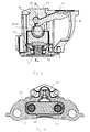
- Figs. 1a and 1b are a perspective view and a cross section, respectively of a open caliper according to the invention,
- Fig. 2 is a cross section of a brake mechanism according to the invention,
- Fig. 3 is a cross section of the brake mechanism of Fig. 2 taken along the line III-III,
- Fig. 4 is a perspective view of the brake mechanism of Figs. 2 and 3, showing the two units forming the brake mechanism,
- Fig. 5 is a perspective view of a second embodiment of a brake mechanism,
- Fig. 6 is a cross section of the brake mechanism of Fig. 5 taken along the line VI-VI of Fig. 7,
- Fig. 7 is a section of the brake mechanism of Fig. 6 taken along the lines VII-VII,
- Fig. 8 is a cross section of the caliper and a further alternative embodiment of the brake mechanism of the invention taken along the lines VIII-VIII of Fig. 9,
- Fig. 9 is a cross section taken along the lines IX-IX of Fig. 8,
- Fig. 10 is a cross section taken along the line X-X of Fig. 9,
- Fig. 11 is a perspective view of the brake mechanism of Figs. 8 to 10, and
- Fig. 12 shows schematically three graphs relating to the force versus stroke of different parts of the brake mechanism.
-
- The brake mechanism of the invention comprises a
lever 1 mounted in abearing bracket 2, to be received in anopening 17 of thecaliper 16. Thelever 1 acts on across bar 3. Thelever 1 is supported byroller bearings bearing bracket 2 and thecross bar 3, respectively. In some embodiments the roller bearing of thebearing bracket 2 is replaced by a plain bearing. Thecross bar 3 has two threaded openings each receiving anadjustment screw 4. Thus, theadjustment screws 4 are rotatably mounted in thecross bar 3. Eachadjustment screw 4 is provided with athrust plate 5, which is to act on a brake pad holder (not shown) or the like. The brake pad will go into contact with the brake disc during activation of the brake. As is known a further brake pad is arranged on the opposite side of the brake disc. The further brake pad is in a known way brought into contact with the brake disc in that theopen caliper 16 is moved at the activation of the brake. In thebearing bracket 2 two adjustment and resetshafts 6 are mounted. When the brake mechanism is assembled the adjustment andreset shafts 6 will be received inside theadjustment screws 4. The adjustment andreset shafts 6 are axially moveable but non-rotatably connected to theadjustment screws 4. Furthermore, the brake mechanism comprises acover 7 fixed to theopen caliper 16 at assembly. Between thebearing bracket 2 and the lever 1 asynchronising shaft 8 is mounted, havingpinions 9 at each end. Thepinions 9 are coupled tocrown wheels 10 non-rotatably connected to the adjustment and resetshafts 6. Thesynchronising shaft 8 carries anadjuster mechanism 12 of known design. Areturn spring 11 is positioned between thecover 7 and thecross bar 3 in order to bring the brake mechanism back to its rest position. Thepinions 9,crown wheels 10, synchronisingshaft 8 and theadjuster mechanism 12 forms a synchronising unit, synchronising the movements of the adjustment and resetshafts 6. - The brake mechanism forms two units or modules. One unit consists of the
lever 1, the synchronising unit and the adjustment andreset shafts 6 all mounted in thebearing bracket 2. In order to keep these parts together as a unit aclip 13 is furnished to hold thelever 1. Thecross bar 3, thecover 7, thereturn spring 11, the adjustment screws 4 and thethrust plates 5 form the second unit of the brake mechanism. The second unit is held together by means of asweep 14. In an alternative embodiment (not shown) the brake mechanism forms a single unit, in which case a sweep or the like will go between thebearing bracket 2 and thecover 7. In further alternative embodiments the different units of the brake mechanism consists of other parts, i.e. the brake mechanism may be divided in different location, and the brake mechanism may be divided in more than two units. Normally the brake mechanism consists of at least two units. - To protect the brake mechanism from road dirt bellows 15 are placed between the
thrust plates 5 and thecover 7. In the shown embodiment thebellows 15 are placed in a heat protection ring. - The
bearing bracket 2 is received in anopening 17 of thecaliper 16. Theopening 17 is placed in the wall of thecaliper 16 furthest from the brake disc. Thus, the caliper is of an open design. Thebearing bracket 2 has ashoulder 18 abutting the inside of thecaliper 16 and thus, thebearing bracket 2 is placed in theopening 17 of thecaliper 16 from the inside. The reaction of the clamp force of the brake is transmitted by means of thebearing bracket 2 to theopen caliper 16. The force of reaction is transmitted via theshoulder 18 of thebearing bracket 2. As the force of reaction is transmitted by means of theshoulder 18 of thebearing bracket 2 the force is transmitted in a area surrounding theopening 17 of thecaliper 16. Thebearing bracket 2 is a loaded part of the brake mechanism and, thus, thebearing bracket 2 and itsshoulder 18 should have enough strength to transmit the force of reaction. A person skilled in the art realises that the shoulder may be placed in the caliper in stead of the bearing bracket, in which case the force of reaction will be transmitted via the edge area of the bearing bracket to the shoulder of the caliper. - A sealing is placed between the
bearing bracket 2 and theopen caliper 16. The sealing between thebearing bracket 2 and theopen caliper 16 is received in a groove of thebearing bracket 2. The groove and thus the sealing may be placed in any position axially or radially in thebearing bracket 2. The inside of theopen caliper 16 may be machined via saidopening 17 of thecaliper 16. - During assembly of the second module it is important that parallelism is established and kept between the thrust units. If there is no parallelism the brake pads will have an uneven wear, which may jeopardise the function of the disc brake.
- In a second embodiment of the brake mechanism the form of the synchronising unit is altered. The synchronising unit is still placed in a
bearing bracket 22 to be received in theopening 17 of thecaliper 16. Anadjuster mechanism 23 of known construction is placed on top of one of the adjustment and resetshafts 6. In the bearing bracket 22 a number ofgear wheels 24 are placed between gear wheels of the adjustment and resetshafts 6. Each gear wheel is placed on apin 25 fixed to the bearingbracket 22. Thegear wheels 24 are placed under acover 42 received in thebearing bracket 22. In Fig. 5 thecover 42 is shown partially broken away for clarity. In the shown example there are fourgear wheels 24 between the gear wheels of the adjustment and resetshafts 6. A person skilled in the art realises that other numbers of gear wheels may be used. As in the previous embodiment thelever 1, bearingbracket 22 and the adjustment and resetshafts 6 form one unit. This unit is joined with a second unit, formed by the other parts of the brake mechanism when the disc brake is assembled. - In this embodiment the
lever 26 is supported by means of a plain bearing received in thebearing bracket 22. Thelever 26 acts on thecross bar 3 by means of an intermediate part 27. The intermediate part has the form of a rocker 29 in this embodiment but may have other forms in another embodiments. - The bearing
bracket 22 has a protrudingpart 32 with a cylindrical surface for co-operation with a cylindrical surface of thelever 26. A plain bearing may be placed between thelever 26 and the protrudingpart 32 of the bearingbracket 22. - The rocker 29 has a cylindrical surface in contact with the cylindrical surface of the
lever 26. The rocker 29 is received in a groove 35 of thecross bar 34. In the end positions of the movement of the rocker 29 it will abut the sides of the groove 35. The contact surfaces of the groove 35 and the rocker 29 are both cylindrical. In an alternative embodiment a cylindrical stud is placed between the rocker 29 and the bottom of the groove 35. - In the embodiment of Figs. 8 to 11 the
lever 31 has a protruding part received in aslide bearing 33 of the bearingbracket 30. Thelever 31 acts on an intermediate part 27 in form of astud 28, which acts on thecross bar 34. - In a further embodiment the lever is turned around compared to the previous embodiments. The turning is made in such a way that the intermediate part 27 and the lever change places. Thus, in this embodiment the intermediate part 27 will be received in the bearing bracket and the lever will be in direct contact with the cross bar.
- The surface of the part of the
lever cross bar 34 via a roller bearing. The intermediate part 27 has two flanges between which thelever lever lever lever bracket lever bracket - When the brake is applied the
lever bracket lever lever - In the embodiment of Figs. 8 to 11 (as well as the embodiment of Figs. 5 to 7) the
cross bar 34 is supported by four protrudingparts 36 of the cross bar and thereturn spring 11 in thecover 7. The protrudingparts 36 of thecross bar 34 abut the inside of theopen caliper 16. The part of thecaliper 16 in contact with the protruding parts of thecross bar 34 is machined to give a smooth surface. The machining is done via theopening 17 of theopen caliper 16. Thereturn spring 11 is guided in an opening in thecross bar 34 and acts between thecross bar 34 and thecover 7. Thereturn spring 11 is received in a holder of thecover 7. Thecross bar 34 is free to move in the thrust direction along the machined part and in one direction perpendicular to the thrust direction. The latter direction is the tangential direction of the brake discs. In an alternative embodiment thecross bar 34 is guide on guide sleeves (not shown) placed around the screws that are used to fix thecover 7 to theopen caliper 16. - When the brake is activated the
lever 31 will press thecross bar 34 and thus thethrust plate 38, via the thrust screws 39 and the brake pads in direction towards the brake disc (not shown). When the brake pads hits the brake disc, the pads will move in the tangential direction of the brake disc a short distance before the brake pads hit a support (not shown). The movement in the tangential direction of the brake disc is normally not more than a few millimetres. Thelever 31, the intermediate part 27, thecross bar 34 and the thrust units of the brake mechanism will follow the brake pads in their movement. During this movement thelever 31 will slide in theplain bearing 33. Thecross bar 34 will move in the tangential direction of the brake disc guided by the protrudingparts 36 of thecross bar 34 or the guide sleeves. Thecover 7 is fixed to thecaliper 16 and will not move. The movement between thecross bar 34 and thecover 7 is taken up by thereturn spring 11. When the brake is released thereturn spring 11 will bring thecross bar 34 back to its centred position. Thelever 31, the intermediate part 27 and the thrust units will move with thecross bar 34 into the centred position. Thus, thereturn spring 11 resets the brake mechanism both in the thrust direction and sideways. The above also apply for the embodiment of Figs. 5 to 7. - The
cover 7 is fixed to theopen caliper 16 by means of screws. Thecover 7 has openings to receive the thrust units. There is a clearance between thecover 7 and the thrust units allowing the thrust units to move in any direction in relation to thecover 7. - The thrust units are in one embodiment connected with a
thrust plate 38, which thrustplate 38 acts on a brake pad. The thrust units each comprises athrust screw 39. The thrust screws 39 have an opening at the bottom, which receives a stud on thethrust plate 38. The studs of thethrust plate 38 and the openings of the thrust screws 39 are formed to lock the thrust screws 39, thus hinder them from rotating. This is important for control of the distance between the brake pads and the brake disc. - One of the thrust units is further furnished with the
adjuster mechanism 23 as stated above and anadjuster shaft 40. Theadjuster mechanism 23 is placed on top of thethrust screw 39. The other thrust unit is furnished with areset shaft 41. Theshafts gear wheels 24. As stated above the set ofgear wheels 24 may be placed in thebearing bracket 30. In another embodiment the seat ofgear wheels 24 are placed between thecover 7 and thethrust plate 38. - The
adjuster mechanism 23 co-operates with thelever lever pin 43. Theshafts screws 39 of the thrust units may rotate relative each other, which is of importance for adjustment of slack in the disc brake. Theshafts - The
adjuster mechanism 23 is of a known construction. When the brake is applied thelever pin 43 will act on theadjuster mechanism 23. When the A-distance has been traversed the housing of theadjuster mechanism 23 is forced to rotate anti-clockwise. The A-distance determines the clearance between the brake pads and the brake disc when the brake is not activated. - During an application stroke the A-distance will first be traversed. At the continued application stroke the
lever pin 43 will rotate the housing of theadjuster mechanism 23. This rotation will be transferred to theadjuster shaft 40. Theadjuster shaft 40 will rotate in relation to the thrust screws 39. Theadjuster shaft 40 and thereset shaft 41 will be rotated concurrent by means of the set ofgear wheels 24. By the rotation of theshafts thrust plate 38 in relation to the brake disc will be altered. This will decrease the slack, if the slack between the brake pads and the brake disc is excessive of a set control distance, until a counter-force and thus a torque is built up when the brake pads engage the brake disc. The force transmission during adjustment occurs by means of a one-way spring drivingly acting between a driving ring and an adjuster hub of the knownadjuster mechanism 23. When the brake pads are in engagement with the brake disc, the torque is such that slip will occur between the housing and the adjustment spring inside theadjuster mechanism 23 at further rotation of the housing. - During the release stroke no torque is transmitted by the one-way spring, which slips in the direction of rotation. If the slack between the brake pads and the brake disc was excessive and this slack has been taken up by rotation of the thrust screws 39 in relation to the
cross bar 34, this new relative position will be maintained during the release stroke. - The
reset shaft 41 is furnished with a suitable head to receive a tool used to reset the thrust units when the brake pads are to be replaced. This movement will be transferred to theadjuster shaft 40 by means of the set ofgear wheels 24. Thereset shaft 41 is rotated in the normal way until the distance between the thrust plates and the brake disc is sufficient to receive the new brake pads. Then thereset shaft 41 is rotated in such a way that the distance between the thrust plates and the brake disc corresponds to the desired running clearance. Thereset shaft 41 is received in a sealed opening of the bearingbracket 30. - As stated above it is possible to control the force amplification characteristic of the brake mechanism, by varying the radiuses R1,R2 of the
lever lever lever lever brake lever lever - Thanks to the module form of the brake mechanism it is easy to change
lever bracket - During assembly of the brake mechanism the module consisting of the
lever bearing bracket caliper 16, then the other module is brought in and thecover 7 is fixed to thecaliper 16. After assembly the brake mechanism will be held together within thebrake caliper 16 by screws 37 fixing thecover 7 to thecaliper 16. - A person skilled in the art realises that the different embodiments of the bearing bracket, the lever and the intermediate part may be combined in many different ways.
Claims (17)
- A brake caliper (16) and a brake mechanism for a disc brake received in said caliper (16), which brake mechanism comprises a brake lever (1,26,31), a cross bar (3,34), one or more thrust plates (5,38) and a cover (7), characterized in that the caliper (16) is of an open design having an opening (17) in the wall furthest from the brake disc and that a bearing bracket (2,22,30) is mounted from the inside of the caliper (16) in said opening (17).
- The brake caliper (16) and mechanism of claim 1, characterized in that the bearing bracket (2,22,30) has a shoulder (18) for transmission of the reaction clamp force to the caliper (16) and that a sealing (19) is placed between the caliper (16) and the bearing bracket (2,22,30) in a groove of the shoulder (18) of the bearing bracket (2,22,30).
- The brake caliper (16) and mechanism of any of the previous claims, characterized in that the opening (17) of the caliper (16) allows machining of the inside of the caliper (16) through said opening (17).
- The brake caliper (16) and mechanism of any of the previous claims, characterized in that the bearing bracket (2,22,30) forms a module of the brake mechanism together with the lever (1,26,31) of the brake mechanism and that the rest of the brake mechanism forms one module held together by a sweep (14).
- The brake caliper (16) and mechanism of claim 4, characterized in that the lever (1,26,31) is fixed to the bearing bracket (2,22,30) by means of clips (13).
- The brake caliper (16) and mechanism of any of the previous claims, characterized in that an adjuster mechanism (12,23) is furnished for adjustment of the clearance between the brake pads and the brake disc, and that the adjuster mechanism (12,23) is a part of an synchronisation unit also comprising adjustment and reset shafts (6,40,41).
- The brake caliper (16) and mechanism of claim 6, characterized in that the synchronisation unit is placed in the bearing bracket (2,22,30).
- The brake caliper (16) and mechanism of claim 7, characterized in that the adjuster mechanism (12) is placed on a synchronising shaft (8) connecting the adjustment and reset shafts (6) by means of pinions (9) and crown wheels (10).
- The brake caliper (16) and mechanism of claim 7, characterized in that the adjuster mechanism (23) is furnished on an adjustment shaft (40) on top of an adjacent a thrust screw (39).
- The brake caliper (21) and mechanism of any of the claims 6 to 9, characterized in that the synchronising unit comprises one or more gear wheels (24) placed between and drivingly connected to the adjustment and reset shafts (6,40,41).
- The brake caliper (16) and mechanism of claim 9, characterized in that the lever (26,31) is acting on the cross bar (3,34) by means of an intermediate part (27).
- The brake caliper (16) and mechanism of claim 11, characterized in that the intermediate part is a rocker (29) received in a groove (35) of the cross bar (34).
- The brake caliper (16) and mechanism of claim 11, characterized in that the intermediate part is a stud (28).
- The brake caliper (16) and mechanism of any of the claims 11 to 13, characterized in that the force amplification characteristics of the brake mechanism is controlled by amending the form and/or the positions of the surfaces in contact of the lever (26,31) and intermediate part (27) and/or the length of the lever (26,31).
- The brake caliper (16) and mechanism of any of the previous claims, characterized in that the cover (7) is fixed to the caliper (16) and that a return spring (11) is positioned between and acting on the cross bar (3,34) and the cover (7).
- The brake caliper (16) and mechanism of claim 15, characterized in that the cross bar (34) is guided in the caliper (16) in such a way that it is allowed to move in the thrust direction and in the tangential direction of the brake discs.
- The brake caliper (16) and mechanism of claim 16, characterized in that the lever (26,31), the intermediate part (27) and the thrust plates (5,38) are movable together with the cross bar (34).
Priority Applications (1)
| Application Number | Priority Date | Filing Date | Title |
|---|---|---|---|
| DE20121237U DE20121237U1 (en) | 2000-05-31 | 2001-05-23 | Brake mechanism and caliper for a disc brake |
Applications Claiming Priority (2)
| Application Number | Priority Date | Filing Date | Title |
|---|---|---|---|
| SE0002058A SE516495C2 (en) | 2000-05-31 | 2000-05-31 | Brake mechanism and caliper for a disc brake |
| SE0002058 | 2000-05-31 |
Publications (2)
| Publication Number | Publication Date |
|---|---|
| EP1160477A2 true EP1160477A2 (en) | 2001-12-05 |
| EP1160477A3 EP1160477A3 (en) | 2003-09-17 |
Family
ID=20279937
Family Applications (1)
| Application Number | Title | Priority Date | Filing Date |
|---|---|---|---|
| EP20010112016 Withdrawn EP1160477A3 (en) | 2000-05-31 | 2001-05-23 | Brake mechanism and caliper for a disc brake |
Country Status (8)
| Country | Link |
|---|---|
| US (1) | US6659235B2 (en) |
| EP (1) | EP1160477A3 (en) |
| KR (1) | KR20010109136A (en) |
| CN (2) | CN1326059A (en) |
| BR (1) | BR0102233A (en) |
| CZ (1) | CZ20011933A3 (en) |
| HU (1) | HUP0102230A3 (en) |
| SE (1) | SE516495C2 (en) |
Cited By (7)
| Publication number | Priority date | Publication date | Assignee | Title |
|---|---|---|---|---|
| US6962244B2 (en) * | 2000-05-31 | 2005-11-08 | Haldex Brake Products Ab | Brake mechanism and a method of controlling force amplification |
| DE102007048350A1 (en) * | 2007-10-09 | 2009-04-23 | Knorr-Bremse Systeme für Nutzfahrzeuge GmbH | Hydraulically operated multi-piston disc brake |
| DE102009013005B3 (en) * | 2009-03-13 | 2010-08-12 | Knorr-Bremse Systeme für Nutzfahrzeuge GmbH | Dual-piston disc brake |
| EP2410198A1 (en) * | 2010-07-21 | 2012-01-25 | KNORR-BREMSE Systeme für Nutzfahrzeuge GmbH | Disc brake for a commercial vehicle |
| DE102012009424A1 (en) * | 2012-05-11 | 2013-11-14 | Knorr-Bremse Systeme für Nutzfahrzeuge GmbH | Disc brake for a commercial vehicle |
| EP3109499A1 (en) * | 2015-06-23 | 2016-12-28 | WABCO Europe BVBA | Disc brake, in particular for a commercial vehicle |
| WO2017036765A1 (en) * | 2015-08-31 | 2017-03-09 | Knorr-Bremse Systeme für Nutzfahrzeuge GmbH | Disc brake having a synchronization unit |
Families Citing this family (28)
| Publication number | Priority date | Publication date | Assignee | Title |
|---|---|---|---|---|
| US7219772B2 (en) * | 2000-08-17 | 2007-05-22 | Knorr-Bremse Systeme Fuer Nutzfahrzeuge Gmbh | Disk brake with a regulating system |
| SE523555C2 (en) * | 2001-09-07 | 2004-04-27 | Haldex Brake Prod Ab | Modular writing brake for a vehicle |
| EP1527289A2 (en) * | 2002-07-29 | 2005-05-04 | KNORR-BREMSE SYSTEME FÜR NUTZFAHRZEUGE GmbH | Disc brake with pressure piece |
| US20050045434A1 (en) * | 2003-04-02 | 2005-03-03 | Franz-Helmut Holl | Vehicle brake assembly having an assembly opening and method of assembly therefor |
| US6811004B1 (en) * | 2003-05-09 | 2004-11-02 | Arvinmeritor Technology, Llc | Vehicle brake assembly having a bearing block closure and method of assembly therefor |
| US20050230197A1 (en) * | 2004-04-14 | 2005-10-20 | Jedele Philip N | One piece sliding brake caliper |
| GB0410841D0 (en) * | 2004-05-14 | 2004-06-16 | Meritor Heavy Vehicle Braking | A parking brake assembly |
| DE102010026076B4 (en) * | 2010-07-05 | 2015-06-11 | Knorr-Bremse Systeme für Nutzfahrzeuge GmbH | Disc brake for a commercial vehicle |
| DE102011119768A1 (en) * | 2011-11-30 | 2013-06-06 | Knorr-Bremse Systeme für Nutzfahrzeuge GmbH | Function unit for adjusting a brake pad of a disc brake |
| DE202012001863U1 (en) * | 2012-02-22 | 2012-03-19 | Haldex Brake Products Ab | Disc brake and sensor device for this |
| DE102013011657B4 (en) * | 2013-07-12 | 2016-08-25 | Knorr-Bremse Systeme für Nutzfahrzeuge GmbH | Disc brake for a commercial vehicle |
| DE102013111258A1 (en) * | 2013-10-11 | 2015-04-30 | Knorr-Bremse Systeme für Nutzfahrzeuge GmbH | Brake carrier for a sliding caliper disc brake |
| KR101632171B1 (en) * | 2013-12-31 | 2016-07-01 | 상신브레이크 주식회사 | A vehicle disc brake having an adjustor fork and an adjustor pin |
| GB2522641B (en) * | 2014-01-30 | 2016-03-09 | Newbridge Brake Ltd | Brake caliper |
| GB2523141C (en) * | 2014-02-14 | 2020-12-02 | Newbridge Brake Ltd | Disc brake caliper |
| DE102014113848A1 (en) * | 2014-09-24 | 2016-03-24 | Knorr-Bremse Systeme für Nutzfahrzeuge GmbH | Clamping device of a disc brake |
| US10247266B2 (en) | 2014-10-30 | 2019-04-02 | Bwi (Shanghai) Co., Ltd. | Brake mounting bracket apparatus |
| CN104728312B (en) * | 2015-01-27 | 2017-04-19 | 武汉元丰汽车零部件有限公司 | Integrated clamp pneumatic disc brake of locating block rotation-prevention structure |
| JP6572102B2 (en) | 2015-04-27 | 2019-09-04 | 曙ブレーキ工業株式会社 | Disc brake device |
| USD771540S1 (en) * | 2015-06-15 | 2016-11-15 | Saf-Holland, Inc. | Brake spider |
| DE102015110676A1 (en) * | 2015-07-02 | 2017-01-05 | Knorr-Bremse Systeme für Nutzfahrzeuge GmbH | Adjustment device for a disc brake |
| USD812534S1 (en) * | 2015-09-11 | 2018-03-13 | Hb Performance Systems, Inc. | Brake caliper housing |
| EP3184841B1 (en) * | 2015-12-22 | 2018-08-22 | Haldex Brake Products AB | Disc brake |
| CN107452269B (en) * | 2017-08-17 | 2023-04-18 | 大连交通大学 | Brake device placed on railway vehicle model and provided with hand pull release function |
| EP3511589B1 (en) * | 2018-01-10 | 2020-08-19 | WABCO Europe BVBA | Disc brake for commercial vehicles |
| EP3623656B1 (en) * | 2018-09-17 | 2021-01-27 | WABCO Europe BVBA | Brake calliper of a disk brake for motor vehicles |
| DE102021126280A1 (en) | 2021-10-11 | 2023-04-13 | Knorr-Bremse Systeme für Nutzfahrzeuge GmbH | Disc brake with a synchronization mechanism |
| EP4310358A1 (en) * | 2022-07-19 | 2024-01-24 | KNORR-BREMSE Systeme für Nutzfahrzeuge GmbH | Brake assembly for braking at least one wheel of a vehicle |
Citations (4)
| Publication number | Priority date | Publication date | Assignee | Title |
|---|---|---|---|---|
| DE19619488A1 (en) * | 1995-05-15 | 1996-11-21 | Lucas Ind Plc | Commercial vehicle disc brakes with lidded housing |
| WO1997022814A1 (en) * | 1995-12-20 | 1997-06-26 | Lucas Industries Plc | Modular disc brake and actuator lever therefor |
| EP0790428A1 (en) * | 1996-02-19 | 1997-08-20 | PERROT BREMSEN GmbH | Caliper disc brake |
| WO1999006725A2 (en) * | 1997-08-02 | 1999-02-11 | Meritor Automotive, Inc. | Improvements relating to disc brakes |
Family Cites Families (52)
| Publication number | Priority date | Publication date | Assignee | Title |
|---|---|---|---|---|
| DE1625826A1 (en) | 1967-09-15 | 1970-02-05 | Teves Gmbh Alfred | Partly lined disc brake |
| FR2082723A5 (en) | 1970-03-25 | 1971-12-10 | Dba | |
| DE2057322C3 (en) | 1970-11-21 | 1981-03-12 | Alfred Teves Gmbh, 6000 Frankfurt | Actuating device for a partially lined disc brake |
| US3724616A (en) | 1971-04-22 | 1973-04-03 | Bendix Corp | Tandem cylinder disc brake |
| US3937304A (en) | 1972-04-11 | 1976-02-10 | Girling Limited | Disc brake calipers |
| US3830343A (en) | 1972-12-12 | 1974-08-20 | Goodrich Co B F | Disc brake with adjustable cam operator and thrust distributer |
| US3837437A (en) | 1973-01-22 | 1974-09-24 | Airheart Prod | Ratchet actuated brake wear compensation |
| CA1030881A (en) | 1975-04-02 | 1978-05-09 | Donald D. Johannesen | Mechanically actuated disc brake |
| US3967705A (en) | 1975-04-02 | 1976-07-06 | The Bendix Corporation | Application adjuster for disc brake |
| US4036329A (en) | 1975-11-12 | 1977-07-19 | Rockwell International Corporation | Disc brake with rotary cam actuated reciprocating pistons |
| US4018310A (en) | 1976-03-15 | 1977-04-19 | The Bendix Corporation | Disc brake |
| US4071118A (en) | 1976-10-22 | 1978-01-31 | The Bendix Corporation | Variable adjuster for disc brake |
| US4184571A (en) | 1976-12-20 | 1980-01-22 | Tokico Ltd. | Disc Brake |
| US4222310A (en) | 1978-12-04 | 1980-09-16 | Eaton Corporation | Brake actuator fastener assembly |
| US4378863A (en) | 1979-08-30 | 1983-04-05 | Lucas Industries Limited | Automatic adjuster for hydraulic brake actuator |
| GB2090355A (en) | 1980-12-12 | 1982-07-07 | Lucas Industries Ltd | Improvements relating to brake adjusters |
| GB2093934B (en) | 1981-03-03 | 1985-01-30 | Lucas Industries Ltd | Improvements relating to the construction of pin sliding calipers |
| FR2504076B1 (en) | 1981-04-17 | 1985-06-14 | Valeo | MECHANICAL BRAKE CONTROL CONSISTING OF AN ECCENTRIC |
| GB2102088A (en) | 1981-07-14 | 1983-01-26 | Automotive Products Plc | Disc brakes |
| DE3348369C2 (en) | 1982-03-11 | 1995-08-31 | Nobuo Mikoshiba | Device forming surface acoustic waves |
| FR2548309B1 (en) | 1983-06-30 | 1985-12-13 | Valeo | COUPLING APPARATUS SUCH AS BRAKE OR THE LIKE HAVING A WEAR RETRACTOR |
| DE3348359C2 (en) | 1983-10-05 | 1991-05-02 | Alfred Teves Gmbh, 6000 Frankfurt, De | Automatic adjusting mechanism for disc brake |
| FR2554194B1 (en) | 1983-10-28 | 1986-01-17 | Dba | AUTOMATICALLY ADJUSTABLE BRAKE MOTOR |
| FR2564925B1 (en) | 1984-05-23 | 1986-10-03 | Dba | AUTOMATICALLY ADJUSTABLE DISC BRAKE |
| DE3438209C2 (en) | 1984-10-18 | 1994-06-23 | Teves Gmbh Alfred | Disc brake, in particular for motor vehicles |
| DE8434025U1 (en) | 1984-11-20 | 1986-03-27 | Lucas Industries P.L.C., Birmingham, West Midlands | Brake actuator |
| JPH0346264Y2 (en) | 1985-03-28 | 1991-09-30 | ||
| DE3610569C2 (en) | 1986-03-27 | 1994-02-17 | Knorr Bremse Ag | Disc brake for vehicles |
| GB8622617D0 (en) | 1986-09-19 | 1986-10-22 | Lucas Ind Plc | Disc brakes |
| DE8633923U1 (en) | 1986-12-18 | 1988-04-21 | Lucas Industries P.L.C., Birmingham, West Midlands, Gb | |
| DE3716202C3 (en) | 1987-05-14 | 2000-03-09 | Knorr Bremse Systeme | Disc brake for vehicles |
| JPS646423A (en) | 1987-06-26 | 1989-01-11 | Sato Road Co Ltd | Water pervious water purifying road structure |
| JPH032022A (en) | 1989-05-31 | 1991-01-08 | Rika Kogyo Kk | Device for controlling picture display in extrusion molding line |
| DE9000257U1 (en) | 1990-01-11 | 1991-05-16 | Lucas Industries P.L.C., Birmingham, West Midlands, Gb | |
| JP2888921B2 (en) | 1990-05-08 | 1999-05-10 | パイオニア株式会社 | Disc playback device |
| JPH0429141A (en) | 1990-05-24 | 1992-01-31 | Seiko Epson Corp | Image forming device and heat developing device |
| DE4031616C2 (en) | 1990-10-05 | 1999-11-25 | Perrot Bremse Gmbh Deutsche | Automatic adjustment device for a mechanically operated sliding calliper disc brake |
| DE4032885A1 (en) | 1990-10-17 | 1992-04-23 | Knorr Bremse Ag | DISC BRAKE FOR VEHICLES, IN PARTICULAR ROAD VEHICLES |
| DE4032886A1 (en) | 1990-10-17 | 1992-04-23 | Knorr Bremse Ag | DISC BRAKE FOR VEHICLES, IN PARTICULAR ROAD VEHICLES |
| GB9100944D0 (en) | 1991-01-16 | 1991-02-27 | Lucas Ind Plc | Brake actuator |
| DE4131631C2 (en) | 1991-09-23 | 1999-05-27 | Julius Dipl Ing Nadas | Mechanical application device for vehicle brakes |
| JP3538198B2 (en) * | 1992-05-05 | 2004-06-14 | メリター・オートモーティヴ・インコーポレーテッド | Disc brake self-adjusting actuator, especially for trucks and buses |
| DE4231560C2 (en) | 1992-09-21 | 2002-07-11 | Perrot Bremse Gmbh Deutsche | Actuator for a sliding caliper disc brake |
| DE4307019B4 (en) | 1993-03-05 | 2006-06-14 | Deutsche Perrot-Bremse Gmbh | Clamping device for a disc brake |
| DE4334914A1 (en) * | 1993-10-13 | 1995-04-20 | Knorr Bremse Systeme | Air operated disc brake |
| DE4430258C1 (en) | 1994-08-25 | 1996-01-04 | Perrot Bremsen Gmbh | Actuating mechanism for disc brake |
| SE505339C2 (en) | 1994-10-24 | 1997-08-11 | Haldex Ab | Disc brake caliper |
| DE19515063C2 (en) | 1995-04-27 | 2002-06-06 | Knorr Bremse Systeme | Disc brake for vehicles, in particular road vehicles |
| US5590742A (en) | 1995-06-07 | 1997-01-07 | Itt Automotive, Inc. | Stamped caliper adapter |
| US5960914A (en) | 1999-02-02 | 1999-10-05 | Goshen Industries Inc. | Mechanical disc brake |
| SE522332C2 (en) * | 2000-05-31 | 2004-02-03 | Haldex Brake Prod Ab | Method of mounting a brake mechanism in a caliper and such caliper |
| SE516513C2 (en) * | 2000-05-31 | 2002-01-22 | Haldex Brake Prod Ab | Disc brake comprising a braking mechanism |
-
2000
- 2000-05-31 SE SE0002058A patent/SE516495C2/en not_active IP Right Cessation
-
2001
- 2001-05-23 EP EP20010112016 patent/EP1160477A3/en not_active Withdrawn
- 2001-05-25 US US09/865,898 patent/US6659235B2/en not_active Expired - Fee Related
- 2001-05-29 KR KR1020010029617A patent/KR20010109136A/en not_active Application Discontinuation
- 2001-05-29 HU HU0102230A patent/HUP0102230A3/en unknown
- 2001-05-31 CN CN01121316A patent/CN1326059A/en active Pending
- 2001-05-31 CN CNB2005101296085A patent/CN100387860C/en not_active Expired - Lifetime
- 2001-05-31 BR BR0102233A patent/BR0102233A/en not_active Application Discontinuation
- 2001-05-31 CZ CZ20011933A patent/CZ20011933A3/en unknown
Patent Citations (4)
| Publication number | Priority date | Publication date | Assignee | Title |
|---|---|---|---|---|
| DE19619488A1 (en) * | 1995-05-15 | 1996-11-21 | Lucas Ind Plc | Commercial vehicle disc brakes with lidded housing |
| WO1997022814A1 (en) * | 1995-12-20 | 1997-06-26 | Lucas Industries Plc | Modular disc brake and actuator lever therefor |
| EP0790428A1 (en) * | 1996-02-19 | 1997-08-20 | PERROT BREMSEN GmbH | Caliper disc brake |
| WO1999006725A2 (en) * | 1997-08-02 | 1999-02-11 | Meritor Automotive, Inc. | Improvements relating to disc brakes |
Cited By (15)
| Publication number | Priority date | Publication date | Assignee | Title |
|---|---|---|---|---|
| US6962244B2 (en) * | 2000-05-31 | 2005-11-08 | Haldex Brake Products Ab | Brake mechanism and a method of controlling force amplification |
| US7980366B2 (en) | 2007-10-09 | 2011-07-19 | Knorr-Bremse Systeme Fuer Nutzfahrzeuge Gmbh | Hydraulically actuated multi-piston disc brake |
| DE102007048350A1 (en) * | 2007-10-09 | 2009-04-23 | Knorr-Bremse Systeme für Nutzfahrzeuge GmbH | Hydraulically operated multi-piston disc brake |
| DE102007048350B4 (en) * | 2007-10-09 | 2010-01-07 | Knorr-Bremse Systeme für Nutzfahrzeuge GmbH | Hydraulically operated multi-piston disc brake |
| DE102009013005C5 (en) * | 2009-03-13 | 2013-05-02 | Knorr-Bremse Systeme für Nutzfahrzeuge GmbH | Dual-piston disc brake |
| DE102009013005B3 (en) * | 2009-03-13 | 2010-08-12 | Knorr-Bremse Systeme für Nutzfahrzeuge GmbH | Dual-piston disc brake |
| EP2410198A1 (en) * | 2010-07-21 | 2012-01-25 | KNORR-BREMSE Systeme für Nutzfahrzeuge GmbH | Disc brake for a commercial vehicle |
| DE102012009424A1 (en) * | 2012-05-11 | 2013-11-14 | Knorr-Bremse Systeme für Nutzfahrzeuge GmbH | Disc brake for a commercial vehicle |
| EP3109499A1 (en) * | 2015-06-23 | 2016-12-28 | WABCO Europe BVBA | Disc brake, in particular for a commercial vehicle |
| WO2016206778A1 (en) * | 2015-06-23 | 2016-12-29 | Wabco Europe Bvba | Disc brake, more particularly for commercial vehicles |
| CN107532667A (en) * | 2015-06-23 | 2018-01-02 | 威伯科欧洲有限责任公司 | Disk brake, in particular for the disk brake of commercial car |
| US20180106307A1 (en) * | 2015-06-23 | 2018-04-19 | Wabco Europe Bvba | Disc brake, more particularly for commercial vehicles |
| US10634201B2 (en) | 2015-06-23 | 2020-04-28 | Wabco Europe Bvba | Disc brake, more particularly for commercial vehicles |
| WO2017036765A1 (en) * | 2015-08-31 | 2017-03-09 | Knorr-Bremse Systeme für Nutzfahrzeuge GmbH | Disc brake having a synchronization unit |
| US10626940B2 (en) | 2015-08-31 | 2020-04-21 | Knorr-Bremse Systeme Fuer Nutzfahrzeuge Gmbh | Disc brake having a synchronization unit |
Also Published As
| Publication number | Publication date |
|---|---|
| CN100387860C (en) | 2008-05-14 |
| KR20010109136A (en) | 2001-12-08 |
| CZ20011933A3 (en) | 2002-01-16 |
| BR0102233A (en) | 2002-02-19 |
| SE0002058L (en) | 2001-12-01 |
| EP1160477A3 (en) | 2003-09-17 |
| HUP0102230A2 (en) | 2002-05-29 |
| US20020017436A1 (en) | 2002-02-14 |
| CN1326059A (en) | 2001-12-12 |
| US6659235B2 (en) | 2003-12-09 |
| SE0002058D0 (en) | 2000-05-31 |
| HU0102230D0 (en) | 2001-08-28 |
| SE516495C2 (en) | 2002-01-22 |
| CN1800671A (en) | 2006-07-12 |
| HUP0102230A3 (en) | 2005-01-28 |
Similar Documents
| Publication | Publication Date | Title |
|---|---|---|
| US6659235B2 (en) | Brake mechanism and caliper for a disc brake | |
| US6668981B2 (en) | Disc brake comprising a brake mechanism | |
| EP1160478B1 (en) | Brake mechanism and a method of controlling force amplification | |
| US7219772B2 (en) | Disk brake with a regulating system | |
| KR100463942B1 (en) | Modular disc brakes and their operating levers | |
| USRE37231E1 (en) | Disc brake caliper | |
| EP1269039B1 (en) | Brake mechanism | |
| US5582273A (en) | Compressed-air disc brake | |
| EP1160479B1 (en) | Modular brake mechanism | |
| JP3538198B2 (en) | Disc brake self-adjusting actuator, especially for trucks and buses | |
| MXPA97002963A (en) | Calibrator for dis brake | |
| GB1571387A (en) | Internal shoe-drum brakes for vehicles |
Legal Events
| Date | Code | Title | Description |
|---|---|---|---|
| PUAI | Public reference made under article 153(3) epc to a published international application that has entered the european phase |
Free format text: ORIGINAL CODE: 0009012 |
|
| AK | Designated contracting states |
Kind code of ref document: A2 Designated state(s): AT BE CH CY DE DK ES FI FR GB GR IE IT LI LU MC NL PT SE TR |
|
| AX | Request for extension of the european patent |
Free format text: AL;LT;LV;MK;RO;SI |
|
| PUAL | Search report despatched |
Free format text: ORIGINAL CODE: 0009013 |
|
| AK | Designated contracting states |
Kind code of ref document: A3 Designated state(s): AT BE CH CY DE DK ES FI FR GB GR IE IT LI LU MC NL PT SE TR |
|
| AX | Request for extension of the european patent |
Extension state: AL LT LV MK RO SI |
|
| RIC1 | Information provided on ipc code assigned before grant |
Ipc: 7F 16D 65/56 B Ipc: 7F 16D 65/18 B Ipc: 7F 16D 55/225 A |
|
| 17P | Request for examination filed |
Effective date: 20040310 |
|
| AKX | Designation fees paid |
Designated state(s): DE |
|
| STAA | Information on the status of an ep patent application or granted ep patent |
Free format text: STATUS: THE APPLICATION IS DEEMED TO BE WITHDRAWN |
|
| 18D | Application deemed to be withdrawn |
Effective date: 20041201 |