EP1160422A2 - Control system of electromagnetically operated valve - Google Patents
Control system of electromagnetically operated valve Download PDFInfo
- Publication number
- EP1160422A2 EP1160422A2 EP01113312A EP01113312A EP1160422A2 EP 1160422 A2 EP1160422 A2 EP 1160422A2 EP 01113312 A EP01113312 A EP 01113312A EP 01113312 A EP01113312 A EP 01113312A EP 1160422 A2 EP1160422 A2 EP 1160422A2
- Authority
- EP
- European Patent Office
- Prior art keywords
- electromagnets
- controller
- movable member
- valve
- vibration
- Prior art date
- Legal status (The legal status is an assumption and is not a legal conclusion. Google has not performed a legal analysis and makes no representation as to the accuracy of the status listed.)
- Granted
Links
Images


Classifications
-
- F—MECHANICAL ENGINEERING; LIGHTING; HEATING; WEAPONS; BLASTING
- F01—MACHINES OR ENGINES IN GENERAL; ENGINE PLANTS IN GENERAL; STEAM ENGINES
- F01L—CYCLICALLY OPERATING VALVES FOR MACHINES OR ENGINES
- F01L9/00—Valve-gear or valve arrangements actuated non-mechanically
- F01L9/20—Valve-gear or valve arrangements actuated non-mechanically by electric means
-
- H—ELECTRICITY
- H01—ELECTRIC ELEMENTS
- H01F—MAGNETS; INDUCTANCES; TRANSFORMERS; SELECTION OF MATERIALS FOR THEIR MAGNETIC PROPERTIES
- H01F7/00—Magnets
- H01F7/06—Electromagnets; Actuators including electromagnets
- H01F7/08—Electromagnets; Actuators including electromagnets with armatures
- H01F7/18—Circuit arrangements for obtaining desired operating characteristics, e.g. for slow operation, for sequential energisation of windings, for high-speed energisation of windings
- H01F2007/1894—Circuit arrangements for obtaining desired operating characteristics, e.g. for slow operation, for sequential energisation of windings, for high-speed energisation of windings minimizing impact energy on closure of magnetic circuit
Definitions
- a valve opening electromagnet 10 is disposed below movable member 6 while having a predetermined clearance from movable member 6, and a valve closing electromagnet 11 is disposed above movable member 6 while having a predetermined clearance from movable member 6. Therefore, movable member 6 is movably disposed in a space between valve opening and closing electromagnets 10 and 11. Both valve opening and closing electromagnets 10 and 11 have guide holes respectively, and guide shaft 7 is reciprocatingly supported to these guide holes.
- the neutral position of movable member 6 is located at a generally center (intermediate) position between valve opening and closing electromagnets 10 and 11.
- valve unit 100 Although only the operation of valve unit 100 during the valve opening period has been discussed hereinabove, the operation during the valve closing period is also executed as is similar to that during the valve opening period. Therefore, the explanation of the operation during the valve closing period is omitted herein.
- controller 21 decides whether engine control unit 22 outputs a valve release command of one of valve units 100 to be checked.
- the routine proceeds to step S2.
- the routine proceeds to step S3.
- controller 21 commands driver circuit 23 to de-energize both of valve opening and closing electromagnets 10 and 11 of the checked valve unit 100. In reply to this commands, the checked valve unit 100 starts a free vibration.
- controller 21 detects the position z of movable member 6 on the basis of the signal form the position sensor 13 and stores the detected position z.
- controller 21 obtains the damping ratio ⁇ from a curve W2 which is obtained by connecting peaks P1 to Pn of movable member of the wave form W1. Since curve W2 is approximated by the following equation (3), the damping ratio ⁇ can be obtained from the information of at least two peaks. More specifically, by detecting time (moment) t and the position z of two peaks (P1 --- Pn) on the curve W2, the damping ratio can be obtained therefrom.
- a ⁇ exp(- ⁇ ⁇ ⁇ n ⁇ t) At In this equation (3), At is an amplitude at time t of the free vibration W1, and a is a maximum amplitude of the free vibration W1.
- controller 21 reads coolant temperature Tw.
- controller 21 commands drive circuit 23 to energize the valve opening electromagnet (VOE) 10 and to execute the landing control. That is, the routine jumps to the landing control routine shown by a flowchart of Fig. 10. After the execution of the landing control routine as to valve opening electromagnet 10, the routine proceeds to step S25.
- the landing control routine will be discussed later.
- controller 21 decides whether engine control unit 22 outputs a single resting command.
- the routine proceeds to step S52.
- the routine jumps to step S53.
Abstract
Description
- The present invention relates to a control system for controlling an electromagnetically operated valve, and more particularly to an electromagnetic valve control system which is capable of executing a soft landing of a movable member onto an electromagnet in a valve open/close control.
- Lately, there are proposed various electromagnetic valve operating systems that employ an electromagnetic actuator comprised of a movable member, a pair of electromagnets and a pair of springs so as to reciprocatingly operate intake and exhaust valves of an internal combustion engine. Generally, it is preferable that a movable member of such a valve operating system is softly landed on an electromagnet while ensuring a required motion performance. A Japanese Patent Provisional Publication No. (Heisei)11-159313 discloses a landing method for softly landing a movable member on an electromagnet in an electromagnetic valve operating system. Such soft landing in this system is achieved by temporally switching off the electromagnet during a period between a switch-on moment of the electromagnet and the landing moment of the movable member. Further, in order to realize a further accurate landing control of an electromagnetic valve unit including a valve and an electromagnetic actuator, there is proposed a control method employing a characteristic representative of a vibration system of the electromagnetic valve unit.
- However, the characteristic of the vibration system of the controlled electromagnetic valve unit is varied according to an operating condition. Particularly, a friction in the electromagnetic valve unit is largely affected by a temperature since the friction largely depends on a characteristic of rubricating oil whose viscosity is varied according to the change of temperature. Therefore, it is difficult to stably execute a required landing control only by a preset characteristic representative quantity.
- It is therefore an object of the present invention to provide a control system for certainly executing a soft landing control of an electromagnetic valve unit by employing an actual characteristic of a vibration system of the electromagnetic valve unit.
- An aspect of the present invention resides in a valve control system comprising an electromagnetic valve unit and a controller. In this system, the electromagnetic valve unit comprises a valve, a pair of electromagnets arranged in spaced relationship from one another in axial alignment with the valve so as to form a space, a movable member axially movably disposed in the space between the electromagnets and interlocked with the valve, and a pair of springs biasing the movable member so as to locate the movable member at an intermediate portion of the space when both of the electromagnets are de-energized. The controller is connected to the electromagnetic valve unit and energizes and de-energizes each of said electromagnets to reciprocatingly displace the valve. The controller is arranged to detect a characteristic of a free vibration of a vibration system in the electromagnetic valve unit when both electromagnets are de-energized, and to estimate at least one of a friction quantity and a spring constant of the vibration system on the basis of the detected characteristic of the free vibration.
- Another aspect of the present invention resides in a method for controlling an electromagnetic valve unit, the electromagnetic valve unit being arranged to operate a valve by electromagnetically controlling a pair of electromagnets so as to displace a movable member disposed in a space between the electromagnets which receiving biasing force of a pair of springs. The method comprises detecting a characteristic of a free vibration of a vibration system in the electromagnetic valve unit when both electromagnets are de-energized; and estimating at least one of a friction quantity and a spring constant of the vibration system on the basis of the detected characteristic of the free vibration.
-
- Fig. 1 is a schematic view showing a control system of electromagnetically operated engine valve according to an embodiment of the present invention.
- Fig. 2 is a movable member velocity function employed in a landing control by the control system of Fig. 1.
- Fig. 3 is a block diagram of a feedback control system of the valve control system schematic view showing an embodiment of the present invention.
- Fig. 4 is a block diagram showing a structure of a controller in the control system.
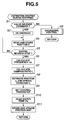
- Fig. 5 is a flowchart showing a first vibration condition estimating routine for estimating the vibration condition during an engine stopping condition.
- Fig. 6 is a graph showing a waveform of a free
vibration of a
movable member 6 at the time after an engine is stopped. - Fig. 7 is a graph showing an example of a map employed for setting a control parameter.
- Fig. 8 is a graph showing an example of a temperature-friction map.
- Fig. 9 is a flowchart showing an energizing control routine executed by the controller of the control system.
- Fig. 10 is a flowchart showing a landing control executed by the controller of the present invention.
- Fig. 11 is a flowchart showing a friction estimating routine for estimating a friction during a normal drive condition executed by the controller.
- Fig. 12 is a flowchart showing a second vibration condition estimating routine for estimating a vibration condition during a single resting condition.
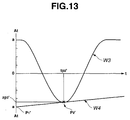
- Fig. 13 is a graph showing a waveform of a temporal free vibration of movable member during the single resting condition.
-
- Referring to Figs. 1 to 13, there is shown an embodiment of a control system for electromagnetically operated engine valves in accordance with the present invention.
- As shown in Fig. 1, the control system according to the present invention is adapted to control intake and exhaust valves of an internal combustion engine for an automotive vehicle. Four
valve units 100 are provided by each cylinder of the engine. Two ofvalve units 100 perform as intake valves, and the other two ofvalve units 100 perform as exhaust valves. More specifically, by each cylinder of the engine, two intake ports communicated with an intake passage and two exhaust ports are formed in acylinder head 1. In order to facilitate the explanation the structure of thevalve units 100, one of thevalve units 100 will be discussed. - A
valve 3 of eachvalve unit 100 is installed to oneport 2 of intake and exhaust ports. Valve 3 penetrates a lower wall of ahousing 12, and is reciprocally movable while being supported bycylinder head 1. Aretainer 4 is fixed to a top end portion ofvalve 3. Avalve closing spring 5 is installed betweenretainer 4 and a wall ofcylinder head 1 faced withretainer 4, andbiases valve 3 into a valve closing direction. - A plate-like
movable member 6 made of soft magnetic material is integrally connected to aguide shaft 7. A lower tip end ofguide shaft 7 is in contact with an upper end ofvalve 3. Aretainer 8 is fixed to an upper portion ofguide shaft 7. Avalve opening spring 9 is installed betweenretainer 8 and an upper wall ofhousing 12. Valve openingspring 9 biasesmovable member 6 integral withguide shaft 7 into the valve opening direction, and thereforevalve 3 is biased into the valve opening direction byvalve opening spring 9 throughguide shaft 7. Accordingly,valve 3 andmovable member 6 are integrally movable in reciprocating motion.
Whenvalve 3 andmovable member 6 are put in the contacted state, valve closing and openingsprings movable member 6 at a neutral position shown in Fig. 1. Although this embodiment according to the present invention has been shown and described such that a shaft ofvalve 3 is separable fromguide shaft 7, it will be understood thatvalve 3 andguide shaft 7 are integrally formed. - A
valve opening electromagnet 10 is disposed belowmovable member 6 while having a predetermined clearance frommovable member 6, and avalve closing electromagnet 11 is disposed abovemovable member 6 while having a predetermined clearance frommovable member 6. Therefore,movable member 6 is movably disposed in a space between valve opening and closingelectromagnets electromagnets guide shaft 7 is reciprocatingly supported to these guide holes. The neutral position ofmovable member 6 is located at a generally center (intermediate) position between valve opening and closingelectromagnets - A
position sensor 13 is installed inhousing 12 and detects a position ofmovable member 6 in the axial direction. In this embodiment, a laser displacement meter is employed asposition sensor 13. - A
controller 21 of the valve control system receives a valve opening/closing command from anengine control unit 22 and outputs an energizing signal to adrive circuit 23 on the basis of the received valve opening/closing command to energizevalve opening electromagnet 10 orvalve closing electromagnet 11.Drive circuit 23 supplies electric current from an electric source (not-shown) to eachelectromagnet movable member 6. - Further,
controller 21 receives a temperature signal indicative of a lubrication oil temperature from atemperature sensor 14 and a current i to be supplied to eachelectromagnet drive circuit 23. In this embodiment, a coolant temperature signal Tw indicative of an engine coolant temperature is inputted to controller 21 as a temperature corresponding to lubrication oil temperature. - Next, the manner of operation of
valve unit 100 will be discussed. - Dimensions and spring constants of the respective valve closing and opening
springs movable member 6 is positioned at the neutral position due to the biasing forces ofsprings electromagnets - When the operation of
movable member 6 is started, an initialization control for positioningmovable member 6 at a seated (landing) position onvalve closing electromagnet 11 is executed in order to decrease energy consumption and to lower a production cost of a current supply circuit ofelectromagnets electromagnets movable member 6 reaches a predetermined initial position corresponding to the valve full close position. - Normal valve operation of each of intake and exhaust valves is started after completing the initialization control. For example, when
valve 3 put in a closed position is moved to an opened position,valve closing electromagnet 11 is first de-energized. In reply to the de-energizing operation ofvalve closing electromagnet 11,movable member 6 is basically displaced downward due to the forces ofsprings valve unit 100 generates energy loss due to some friction based on a viscosity of lubrication oil.
In order to cancel this energy loss and to maintain the normal valve operation,valve opening electromagnet 10 is energized during an opening process ofmovable member 6. - A graph of Fig. 2 shows a locus of
movable member 6. In this graph, a horizontal axis represents a position z ofmovable member 6 when the neutral position ofmovable member 6 is set at an origin point, and a vertical axis represents a velocity v ofmovable member 6 at the position z.
By de-energizingvalve closing electromagnet 11,movable member 6 to have been attracted byvalve closing electromagnet 11 starts free vibration from a position z = -z1 (where z1 > 0). In this situation, the motion in this spring-mass-damper vibration system is generally determined by the following equation (1).In this equation (1), c is a damping coefficient and particularly denotes a magnitude of friction.
- At the moment when
movable member 6 is displaced to a position where magnetic force ofvalve opening electromagnet 10 becomes effective tomovable member 6,valve opening electromagnet 10 is energized.Movable member 6 is biased by this magnetic force ofvalve opening electromagnet 10 and is displaced to a predetermined position (z = z3). By supplying a predetermined electric current tovalve opening electromagnet 10 during this period,movable member 6 is accelerated asmovable member 6 approachesvalve opening electromagnet 10. In order prevent a radial collision betweenmovable member 6 andvalve opening electromagnet 10, a landing control for softly landingmovable member 6 onvalve opening electromagnet 10 is executed by decelerating the velocity v ofmovable member 6. - In order to achieve this landing control (collision preventing control), velocity v of
movable member 6 after starting energizingvalve opening electromagnet 10 is controlled at a target velocity r according to the position z by means of a feedback control, as shown in Fig. 3. In this control system,controller 21 detects velocity v ofmovable member 6 and outputs the energizing command so that the detected velocity v follows up the target velocity r. By energizingvalve opening electromagnet 10 throughdrive circuit 23 according to the energizing current, it becomes possible to landmovable member 6 onvalve opening electromagnet 10 at a predetermined velocity such as 0.1 (m/s) or less. Further, it becomes possible to stopmovable member 6 at a position wheremovable member 6 has a predetermined gap with respect tovalve opening electromagnet 10 and to maintainmovable member 6 at the gapped position until the next closing operation is executed. - Although only the operation of
valve unit 100 during the valve opening period has been discussed hereinabove, the operation during the valve closing period is also executed as is similar to that during the valve opening period. Therefore, the explanation of the operation during the valve closing period is omitted herein. - When the above mentioned landing control is executed, the accuracy of the control is improved by employing a model constant such as mass m, friction c and spring constant k for a controlled system of
valve unit 100. However, friction c tends to largely vary according to the change of a temperature particularly to the change of oil temperature. Further, it is not certain that spring constant k is always constant, and rather the spring constant k may vary by each valve at an initial installation, that is, there is a possibility that spring constant k ofspring - With the thus arranged valve control system according to the present invention, it is possible to monitor the characteristic of the free vibration of
valve unit 100 by putting both of valve opening and closingelectromagnets electromagnets valve unit 100 and the spring constant k of the sum ofsprings - Such a free vibration is completely executed when the engine is stopped and when both of valve opening and closing
electromagnets valve units 100 for the intake and exhaust valves even during the engine operating condition. In this embodiment according to the present invention, fourvalve units 100 are installed to each cylinder of the engine. Therefore, by keeping the closed condition of one of two intake valves and by operating another intake valve to intake gas mixture, it becomes possible to execute such a free vibration of valve unit for the temporally resting intake valve. Hereinafter, a condition that one of intake valves or exhaust valves is put in a resting condition is called a single resting condition. That is, by once releasing the resting valve during a low load drive condition and during the single resting condition, it becomes possible to execute the free vibration of thevalve unit 100 for the resting valve. - Hereinafter, the control procedure of the valve control system according to the present invention will be discussed. The estimating process of friction c and spring constant k is also discussed with reference to Figs. 4 to 13.
- Fig. 4 shows a block diagram of
controller 21 of the valve control system according to the present invention. - A stopping vibration
condition estimating section 31 ofcontroller 21 monitors a free vibration obtained by de-energizing thevalve unit 100 in the engine stopping condition. On the basis of the obtained characteristic of the free vibration of the restingvalve unit 100, stopping vibrationcondition estimating section 31 estimates friction c at the temperature in this condition and spring constant k of the composition ofsprings - A single resting vibration
condition estimating section 32 ofcontroller 21 monitors a free vibration obtained by temporally de-energizing thevalve unit 100 in the single resting condition. Single resting vibrationconditioner estimating section 32 can estimate friction c at the present temperature on the basis of the monitored characteristic of the free vibration. Although it is possible to estimate spring constant k in addition to the estimation of friction c, the aging fluctuation of spring constant k is small as compared with the aging fluctuation of friction c. Further, it is possible to estimate spring constant k by every engine stopping condition as mentioned above. Therefore, in this embodiment, during the single resting condition, the estimation of spring constant k is omitted. -
Controller 21 stores friction c estimated at stopping vibrationcondition estimating section 31 and single-resting vibrationcondition estimating section 32 and coolant temperature Tw at the estimated period in amap section 33 in the form of a temperature-friction relationship. When the detected coolant temperature Tw corresponds to the coolant temperature stored in themap 33, the estimated friction c at the detected coolant temperature Tw is stored instead of the previously stored friction data. - A normal-operation
friction estimating section 34 ofcontroller 21 estimates the friction c at the present temperature on the basis of the detected coolant temperature Tw and with reference to the temperature-friction map 33. When the detected coolant temperature Tw does not correspond to the stored temperature, friction c is interpolated from the stored two temperature-friction data adjacent to the detected coolant temperature. - A control
parameter setting section 35 of controller sets an optimum control parameter PRM on the basis of friction c estimated at stopping vibrationcondition estimating section 31 or normal-operationfriction estimating section 34 and spring constant k estimated at stopping vibrationcondition estimating section 31. For example, the control gain (feedback gain) G of the landing controller shown in Fig. 3 may be varied according to friction c and spring constant k. - A
main processing section 36 ofcontroller 21 receives the estimated friction c and the estimated spring constant k and the control parameter PRM and the position signal z.Main processing section 36 outputs energizing commands to drivecircuit 23 for energizingvalve opening electromagnet 10 andvalve closing electromagnet 11, respectively, upon taking account of the received information whenmain processing section 36 receives valve opening/closing command from anengine control unit 22. - Next, the control procedure of
controller 21 will be discussed with reference to a flowchart of Fig. 5, which shows an estimation processing routine fro estimating a vibration condition during an engine stopping condition. - At step S1,
controller 21 decides whetherengine control unit 22 outputs a valve release command of one ofvalve units 100 to be checked.
When the decision at step S1 is affirmative, the routine proceeds to step S2. When the decision at step S1 is negative, the routine proceeds to step S3. - At step S2,
controller 21commands driver circuit 23 to de-energize both of valve opening and closingelectromagnets valve unit 100. In reply to this commands, the checkedvalve unit 100 starts a free vibration. - At step S3 following to the negative decision at step S1,
controller 21 commands drivecircuit 21 to execute an energizing control for valve opening and closingelectromagnets - At step S4 following to the execution of step S2,
controller 21 detects the position z ofmovable member 6 on the basis of the signal form theposition sensor 13 and stores the detected position z. - At step S5,
controller 21 decides whethermovable member 6 is put in a stationary state or not. When the decision at step S5 is affirmative, the routine proceeds to step S6. When the decision at step S5 is negative, the routine returns to step S4. - At step S6,
controller 21 calculates the frequency ωn of the free vibration on the basis of the position information accumulatedly stored.
At step S7,controller 21 calculates a damping ratio ζ of the free vibration. In this embodiment, on the basis of the stored information as to the position z during the free vibration,controller 21 constructs the wave form W1 of the free vibration as shown in Fig. 6, and calculates the frequency ωn of the free vibration on the basis of the representative cycle of the wave form W1 and the following equation (2). - Further,
controller 21 obtains the damping ratio ζ from a curve W2 which is obtained by connecting peaks P1 to Pn of movable member of the wave form W1. Since curve W2 is approximated by the following equation (3), the damping ratio ζ can be obtained from the information of at least two peaks. More specifically, by detecting time (moment) t and the position z of two peaks (P1 --- Pn) on the curve W2, the damping ratio can be obtained therefrom.movable member 6 may be employed as the maximum amplitude of this vibration system. Therefore, in this embodiment, the position z1 shown in Fig. 2 is employed as the maximum amplitude a. Further, the maximum amplitude a may be set at a constant value such as 4 mm. Therefore, if the valve a of the equation (3) has been previously set, it is possible to obtain the damping ratio ζ from the information including time t and position z of one peak and the equation (3). Steps S4 to S7 constitute a free vibration characteristic detecting means. - A step S8,
controller 21 estimates friction c and spring constant k on the basis of the calculated frequency ωn and damping ratio ζ. Since the wave form of the free vibration can be theoretically determined on the basis of mass m, friction c and spring constant k of the vibration system, it is possible to estimate the actual friction c and the actual spring constant k from the actually detected frequency ωn and damping ratio ζ and the following equations (4) and (5). - This step S8 acts as a vibration condition detecting means.
- At step S9,
controller 21 sets an optimum control parameter PRM with respect to the estimated friction c and spring constant k. For example, the relationship among optimum control parameter PRM, friction c and spring constant k has been previously obtained as shown in Fig. 7 by experiments and stored in a map indicative of this relationship shown in Fig. 7. Accordingly,controller 21 obtains the control parameter PRM employed in the actual control from the map determined on the basis of the estimated friction c and the spring constant k.
This step S9 constitutes a control parameter setting means. - The control parameter PRM set at step S9 corresponds with a control gain G employed in the energizing control for
electromagnets movable member 6 is estimated from an observer of the landing control, friction c and spring constant k may be directly included in designing the observer. - At step S10,
controller 21 reads coolant temperature Tw. - At step S11,
controller 21 stores the estimated friction c as a relationship to the coolant temperature Tw and updates the temperature-friction map 33 by each estimation of friction c. Referring to Fig. 8, the temperature-friction map 33 at an initial condition has stored only the coordinate axes coolant temperature Tw and friction c, and then gradually increases the information by each estimation time of friction c and the temperature detected. It is preferable to update themap 33 with the new data when coolant temperature Tw of the new data whose corresponding coolant temperature Tw has already been stored is obtained. By this updating operation, themap 33 is gradually perfected, particularly fulfills the data in an ordinary temperature. This step S11 constitutes a friction quantity storing means. - Next, the normal operation control routine executed by
controller 21 will be discussed with reference to a flowchart of Fig. 9. - At step S21,
controller 21 reads the valve opening/closing command for eachvalve unit 100 for each of intake and exhaust valves. - At step S22,
controller 21 decides whether the read command is the valve opening command or not. When the decision at step S22 is affirmative, the routine proceeds to step S23. When the decision at step S22 is negative, the routine proceeds to step S25. - At step S23,
controller 21commands driver circuit 23 to de-energize the valve closing electromagnet (VCE) 11. - At step S24,
controller 21 commands drivecircuit 23 to energize the valve opening electromagnet (VOE) 10 and to execute the landing control. That is, the routine jumps to the landing control routine shown by a flowchart of Fig. 10. After the execution of the landing control routine as tovalve opening electromagnet 10, the routine proceeds to step S25. The landing control routine will be discussed later. - At step S25,
controller 21 decides whether the received commands include the valve close command or not. When the decision at step S25 is affirmative, the routine proceeds to step S26. When the decision at step S25 is negative, the routine proceeds to a return step. - At step S26 following to the affirmative decision at step S25,
controller 21commands driver circuit 23 to de-energize the valve opening electromagnet (VOE) 10. - At step S27,
controller 21 commands drivecircuit 23 to energize the valve closing electromagnet (VCE) 11 and to execute the landing control of thevalve closing electromagnet 11. That is, the routine jumps to the landing control routine shown by a flowchart of Fig. 10. After the execution of the landing control routine as tovalve closing electromagnet 11, the routine proceeds to the return block. - Next, the landing control will be discussed with reference to the flowchart of Fig. 10. As mentioned above, this routine is executed as a subroutine at steps S24 and S27, separately.
- At step S31,
controller 21 reads the position z ofmovable member 6. - At step S32,
controller 21 decides whether the read position z is greater than or equal to the value z2 or not. That is,controller 21 decides whether or notmovable member 6 is moved to a position where the electromagnetic force ofvalve opening electromagnet 10 affectsmovable member 6 as shown in Fig. 2. When the decision at step S32 is negative (z < z2), the routine returns to step S31. That is, steps S31 and S32 are repeated until the decision at step S32 becomes affirmative. When the decision at step S32 is affirmative (z ≥ z2), the routine proceeds to step S33. - At step S33,
controller 21 executes the control parameter setting control to set control parameter PRM. More specifically, the routine jumps to the control parameter setting control routine shown by a flowchart of Fig. 11. After the execution of the control parameter setting control, the routine returns to step S34. The control parameter setting routine will be discussed later. - At step S34,
controller 21 detects velocity v ofmovable member 6. In this embodiment,controller 21 obtains velocity v on the basis of position z detected byposition sensor 13. More specifically, velocity v ofmovable member 6 is obtained on the basis of a displacement per a unit time (v = dz/dt), such as a difference (zn - zn-1) between a previous position zn-1 and a present position zn. Velocity v ofmovable member 6 may be obtained by providing a velocity sensor for detecting the velocity ofmovable member 6, or designing an observer of the velocity v and estimating velocity v from this observer. In such a case, it is necessary to determine a model of a condition of a controlled system in order to design the observer of velocity v. Taking account of a friction resistance applied to movable portions of the controlled system (valve unit 100) and the elasticity ofsprings - At step S35,
controller 21 calculates target velocity r. Target velocity r is a function set according to position z ofmovable member 6, and it is preferable that the target velocity rz2 at position z2 is set equal to a velocity vz2 derived from the free vibration (rz2 = vz2) when the position z is at a switching start point z2 (z = z2). As to the landing completion point, if it is set that when z = z3 the velocity vz3 is zero (vz3 = 0), it becomes possible to prevent the collision betweenmovable member 6 andvalve opening electromagnet 10 and to staymovable member 6 at a predetermined position until the next valve closing operation. - At step S36,
controller 21 calculates a target electric current i* to be supplied tovalve opening electromagnet 10 in a manner of obtaining a feedback correction current by multiplying a difference (r-v) between target velocity r and actual velocity v ofmovable member 6 with control gain G and by adding the feedback correction current to an actual electric current i (i* = G(r-v) + i). - At step S37,
controller 21 controls drivecircuit 23 to supply target electric current i* to thecorresponding electromagnet movable member 6, and the electric current to be actually supplied to the electromagnet is determined. Further, the attracting force f of the electromagnet is applied tomovable member 6 according to the actual electric current and the position z ofmovable member 6. A movable section including themovable member 6 is driven by the attracting force f and the biasing force ofsprings valve member 3 is driven toward the full open position. - Next, the control parameter setting control will be discussed with reference to the flowchart of Fig. 11.
- At step S41,
controller 21 reads coolant temperature Tw. - At step S42,
controller 21 estimates friction c with reference to themap 33. - At step S43, controller sets control parameter PRM on the basis of friction c estimated at step S43 and spring constant k estimated at step S8 and with reference to the map shown in Fig. 8. After the execution of step S43, the routine returns to the routine of the landing control.
- With reference to a flowchart of Fig. 12, the vibration condition estimating routine for estimating the vibration condition of the vibration system during the single resting condition will be discussed.
- At step S51,
controller 21 decides whetherengine control unit 22 outputs a single resting command. When the decision at step S51 is affirmative, the routine proceeds to step S52. When the decision at step S51 is negative, the routine jumps to step S53. - At step S52,
controller 21 commands drivecircuit 23 to energizevalve closing electromagnet 11 ofvalve unit 100 to be set in a resting state. By the execution of step S52, the corresponding intake valve is maintained at the closed state. That is, the corresponding intake valve is put in the resting condition. - At step S53 following to the negative decision at step S51,
controller 21 executes the normal energizing control for each ofelectromagnets - At step S54 following to the execution of step S54,
controller 21 decides whether the estimation of friction c is executed or not. When the decision at step S54 is affirmative, the routine proceeds to step S55. When the decision at step S54 is negative, the routine jumps to the return step to maintain the closing condition of the intake valve. - At step S55,
controller 21 commands drivecircuit 23 to de-energize the electromagnet of the resting valve, that is, to de-energizevalve closing electromagnet 11 in order to start the free vibration of the restingvalve unit 100. - At step S56,
controller 21 detects the position z ofmovable member 6 on the basis of the signal fromposition sensor 13 and stores the detected position z. - At step S57,
controller 21 decides whethermovable member 6 has moved inversely or not. It is possible to detect the inverse motion ofmovable member 6 by deciding whether velocity v ofmovable member 6 becomes zero at the first time aftervalve closing electromagnet 11 releasesmovable member 6 in the resting state. When decision at step S57 is negative, the routine returns to step S56 to repeat steps S56 and S57 until the decision at step S57 becomes affirmative. When the decision at step S57 is affirmative, the routine proceeds to step S58. - At step S58,
controller 21 executes the landing control ofvalve closing electromagnet 11 to smoothly and softly landmovable member 6 onvalve closing electromagnet 11. - At step S59,
controller 21 calculates damping ratio ζ. In this embodiment,controller 21 partially obtains a free vibration wave form W3 shown in Fig. 13 by accumulating the position z stored at step S56 until detecting the inverse motion ofmovable member 6. On the basis of the obtained wave form W3, at least two peaks P1' and P2' of the displacement ofmovable member 6 are detected, and damping ratio ζ is estimated from the line W4 connecting the peaks P1' and P2' of wave form W3 as shown in Fig. 13. - Since the wave form W3 can be approximated by the equation (3) under the condition that the maximum amplitude a is z1 (a=z1), damping ratio ζ may be obtained by the equation (3) and the time tP2, and the position zP2, of one peak P2'. Further, spring constant k may be estimated by approximately obtaining a cycle T in a manner of multiplying 2 with the time period between the peaks P1' and P2'. In this routine, step S56, S57 and S58 constitute a free vibration characteristic detecting means.
- At step S60,
controller 21 estimates friction c on the basis of the calculated damping ratio ζ and the frequency ωn of the free vibration and the equation (5). - At step S61,
controller 21 sets optimum control parameter PRM according to the estimated friction c and the spring constant k with reference to the map shown in Fig. 8. This step S61 constitutes a second control parameter setting means. The control parameter PRM set at step S61 may relate to control gain G employed in the energizing control ofelectromagnets movable member 6 is estimated by means of the observer in the landing control, friction c estimated at step S60 may be directly employed in the design of the observer. - At step S62,
controller 21 detects coolant temperature Tw. - At step S63,
controller 21 stores the estimated friction c and the coolant temperature Tw at the time of the estimation of friction c into the temperature-friction map 33. Themap 33 can be updated even during the single resting period. This step S63 constitutes a friction quantity storing means. - With the thus arranged control system according to the present invention, it is possible to estimate an actual friction at the temperature at the timing of the single resting, and therefore it becomes possible to increase the times of the estimations of the actual friction c. Accordingly, it becomes possible to improve the relationship between the friction c and the temperature for the landing control.
- Although the embodiment according to the present invention has been shown and described such that control parameter PRM is set on the basis of the estimated friction c and spring constant k, the present invention is not limited to this and may be arranged to estimate friction c and spring constant k even when the setting of the control parameter is not set. Further, control parameter PRM may be simply set on the basis of one of the estimated friction c and the estimated spring constant k, or one of the friction c and the estimated spring constant k may be estimated and the other may employ an initial valve thereof.
- The entire contents of Japanese Patent Application No. 2000-166532 filed on June 2, 2000 in Japan are incorporated herein by reference.
- Although the invention has been described above by reference to certain embodiments of the invention, the invention is not limited to the embodiments described above. Modifications and variations of the embodiments described above will occur to those skilled in the art, in light of the above teaching. The scope of the invention is defined with reference to the following claims.
Claims (13)
- A valve control system comprising:an electromagnetic valve unit comprisinga valve,a pair of electromagnets arranged inspaced relationship from one another in axialalignment with the valve so as to form a space,a movable member axially movably disposed in the space between the electromagnets, themovable member being interlocked with the valve,a pair of springs biasing the movable member so as to locate the movable member at an intermediate portion of the space when both of the electromagnets are de-energized; anda controller connected to said electromagnetic valve unit, said controller energizing and de-energizing each of said electromagnets to reciprocatingly displace the valve,said controller being arranged to detect a characteristic of a free vibration of a vibration system in said electromagnetic valve unit when both electromagnets are de-energized, and to estimate at least one of a friction quantity and a spring constant of the vibration system on the basis of the detected characteristic of the free vibration.
- The control system as claimed in claim 1,
wherein said controller controls electric current to be supplied to electromagnets to control the operation of the valve. - The control system as claimed in claim 1, wherein said controller controls electric current to be supplied to electromagnets based on the estimated characteristic of the vibration system of said valve unit.
- The control system as claimed in claim 1,
wherein said controller detects an actual damping ratio of the vibration system as the characteristic of the vibration system. - The control system as claimed in claim 1,
wherein said controller detects one of a cycle and a frequency of the free vibration as a characteristic. - The control system as claimed in claim 1,
wherein said controller generates the free vibration of the vibration system by de-energizing both of the electromagnets when said electromagnetic valve unit is put in a stopped condition. - The control system as claimed in claim 1,
wherein said controller generates the free vibration by de-energizing the electromagnet, which is of said electromagnetic valve unit adapted to one of the plurality of valves and which has been energized to keep the valve in a close condition, when the control system is adapted to control intake and exhaust valves of an internal combustion engine and when a plurality of intake valves or a plurality of exhaust valves are provided to each cylinder of the engine. - The control system as claimed in claim 3,
wherein said controller determines a control parameter employed for controlling the electric current to be supplied to said electromagnets, on the basis of at least one of the friction quantity and the spring constant. - The control system as claimed in claim 1,
wherein said controller detects a temperature indicative of a temperature of lubrication oil for the engine, and said controller stores the estimated friction quantity with the temperature at the estimated condition. - The control system as claimed in claim 9,
wherein said controller determines a control parameter employed for controlling electric current to be supplied to said electromagnets, on the basis of at the friction quantity stored in said controller. - An engine valve control system for electromagnetically controlling each of intake and exhaust valves of an internal combustion engine, said valve control system comprising:
an electromagnetic valve unit comprisinga pair of electromagnets arranged inspaced relationship from one another in axialalignment with the valve so as to form a space,a movable member axially movably disposed in the space between the electromagnets, the movable member being contacted with the valve,a pair of springs biasing the movable member so as to locate the movable member at an intermediate portion of the space when both of the electromagnets are de-energized; anda controller connected to said electromagnetic valve unit, said controller detecting a characteristic of a free vibration of a vibration system in said electromagnetic valve unit when both electromagnets are de-energized, said controller estimating at least one of a friction quantity and a spring constant of the vibration system on the basis of the detected characteristic of the free vibration, said controller controlling said electromagnetic valve unit on the basis of a control parameter determined by one of the estimated friction quantity and the estimated spring constant so as to reciprocatingly displace the valve between an opening state and a closing state. - A control system for controlling an electromagnetic valve unit, the electromagnetic valve unit comprising a valve, a pair of electromagnets arranged in spaced relationship from one another in axial alignment with the valve so as to form a space, a movable member axially movably disposed in the space between the electromagnets while being interlocked with the valve, and a pair of springs biasing the movable member so as to locate the movable member at an intermediate portion of the space when both of the electromagnets are de-energized, the control system comprising;free-vibration characteristic detecting means that detects a characteristic of a free vibration of a vibration system in the electromagnetic valve unit when both electromagnets are de-energized;vibration-condition estimating means that estimates at least one of a friction quantity and a spring constant of the vibration system on the basis of the detected characteristic of the free vibration; andcontrolling means controlling electric current supplied to the electromagnets based on the estimated one of the friction quantity and the spring constant to reciprocatingly displace the valve.
- A method for controlling an electromagnetic valve unit, the electromagnetic valve unit being arranged to operate a valve by electromagnetically controlling a pair of electromagnets so as to displace a movable member disposed in a space between the electromagnets which receiving biasing force of a pair of springs, the method comprising:detecting a characteristic of a free vibration of a vibration system in the electromagnetic valve unit when both electromagnets are de-energized; andestimating at least one of a friction quantity and a spring constant of the vibration system on the basis of the detected characteristic of the free vibration.
Applications Claiming Priority (2)
| Application Number | Priority Date | Filing Date | Title |
|---|---|---|---|
| JP2000166532 | 2000-06-02 | ||
| JP2000166532A JP3617413B2 (en) | 2000-06-02 | 2000-06-02 | Control device for electromagnetically driven valve |
Publications (3)
| Publication Number | Publication Date |
|---|---|
| EP1160422A2 true EP1160422A2 (en) | 2001-12-05 |
| EP1160422A3 EP1160422A3 (en) | 2003-05-14 |
| EP1160422B1 EP1160422B1 (en) | 2005-02-09 |
Family
ID=18669832
Family Applications (1)
| Application Number | Title | Priority Date | Filing Date |
|---|---|---|---|
| EP01113312A Expired - Lifetime EP1160422B1 (en) | 2000-06-02 | 2001-05-31 | Control system of electromagnetically operated valve |
Country Status (4)
| Country | Link |
|---|---|
| US (1) | US6412456B2 (en) |
| EP (1) | EP1160422B1 (en) |
| JP (1) | JP3617413B2 (en) |
| DE (1) | DE60108806T2 (en) |
Cited By (2)
| Publication number | Priority date | Publication date | Assignee | Title |
|---|---|---|---|---|
| EP1344902A3 (en) * | 2002-03-11 | 2007-09-26 | Toyota Jidosha Kabushiki Kaisha | Electromagnetically driven valve control apparatus |
| EP1455058A3 (en) * | 2003-03-05 | 2008-10-15 | Toyota Jidosha Kabushiki Kaisha | Electromagnetic valve drive system and method |
Families Citing this family (4)
| Publication number | Priority date | Publication date | Assignee | Title |
|---|---|---|---|---|
| US6536387B1 (en) * | 2001-09-27 | 2003-03-25 | Visteon Global Technologies, Inc. | Electromechanical engine valve actuator system with loss compensation controller |
| US6681728B2 (en) * | 2001-11-05 | 2004-01-27 | Ford Global Technologies, Llc | Method for controlling an electromechanical actuator for a fuel air charge valve |
| SE529328C2 (en) * | 2005-11-15 | 2007-07-10 | Johan Stenberg | Control system and method for controlling electromagnetically driven pumps |
| US9589594B2 (en) | 2013-02-05 | 2017-03-07 | Alc Holdings, Inc. | Generation of layout of videos |
Citations (7)
| Publication number | Priority date | Publication date | Assignee | Title |
|---|---|---|---|---|
| US4544986A (en) * | 1983-03-04 | 1985-10-01 | Buechl Josef | Method of activating an electromagnetic positioning means and apparatus for carrying out the method |
| EP0810350A1 (en) * | 1996-05-28 | 1997-12-03 | Toyota Jidosha Kabushiki Kaisha | Method of detecting fault in electromagnetically-actuated intake or exhaust valve |
| US5743221A (en) * | 1995-07-22 | 1998-04-28 | Fev Motorentechnik Gmbh & Co. Kg | Method for a throttle-free load control of an internal combustion engine by means of variably controllable cylinder valves |
| US5797360A (en) * | 1996-06-14 | 1998-08-25 | Fev Motorentechnik Gmbh & Co Kg | Method for controlling cylinder valve drives in a piston-type internal combustion engine |
| WO1999013202A1 (en) * | 1997-09-11 | 1999-03-18 | Daimlerchrysler Ag | Electromagnetically actuatable adjustment device and operational method therefor |
| US5905625A (en) * | 1996-10-02 | 1999-05-18 | Fev Motorentechnik Gmbh & Co. Kg | Method of operating an electromagnetic actuator by affecting the coil current during armature motion |
| US6041667A (en) * | 1997-07-31 | 2000-03-28 | Fev Motorentechnik Gmbh & Co. Kg | Method of operating an electromagnetic actuator with consideration of the armature motion |
Family Cites Families (3)
| Publication number | Priority date | Publication date | Assignee | Title |
|---|---|---|---|---|
| DE3810194C1 (en) * | 1988-03-25 | 1989-08-24 | Daimler-Benz Aktiengesellschaft, 7000 Stuttgart, De | |
| JP3877851B2 (en) | 1997-11-27 | 2007-02-07 | 株式会社日本自動車部品総合研究所 | Solenoid valve drive |
| JP3629362B2 (en) * | 1998-03-04 | 2005-03-16 | 愛三工業株式会社 | Driving method of electromagnetic valve for driving engine valve |
-
2000
- 2000-06-02 JP JP2000166532A patent/JP3617413B2/en not_active Expired - Fee Related
-
2001
- 2001-05-15 US US09/854,480 patent/US6412456B2/en not_active Expired - Lifetime
- 2001-05-31 EP EP01113312A patent/EP1160422B1/en not_active Expired - Lifetime
- 2001-05-31 DE DE60108806T patent/DE60108806T2/en not_active Expired - Lifetime
Patent Citations (7)
| Publication number | Priority date | Publication date | Assignee | Title |
|---|---|---|---|---|
| US4544986A (en) * | 1983-03-04 | 1985-10-01 | Buechl Josef | Method of activating an electromagnetic positioning means and apparatus for carrying out the method |
| US5743221A (en) * | 1995-07-22 | 1998-04-28 | Fev Motorentechnik Gmbh & Co. Kg | Method for a throttle-free load control of an internal combustion engine by means of variably controllable cylinder valves |
| EP0810350A1 (en) * | 1996-05-28 | 1997-12-03 | Toyota Jidosha Kabushiki Kaisha | Method of detecting fault in electromagnetically-actuated intake or exhaust valve |
| US5797360A (en) * | 1996-06-14 | 1998-08-25 | Fev Motorentechnik Gmbh & Co Kg | Method for controlling cylinder valve drives in a piston-type internal combustion engine |
| US5905625A (en) * | 1996-10-02 | 1999-05-18 | Fev Motorentechnik Gmbh & Co. Kg | Method of operating an electromagnetic actuator by affecting the coil current during armature motion |
| US6041667A (en) * | 1997-07-31 | 2000-03-28 | Fev Motorentechnik Gmbh & Co. Kg | Method of operating an electromagnetic actuator with consideration of the armature motion |
| WO1999013202A1 (en) * | 1997-09-11 | 1999-03-18 | Daimlerchrysler Ag | Electromagnetically actuatable adjustment device and operational method therefor |
Cited By (2)
| Publication number | Priority date | Publication date | Assignee | Title |
|---|---|---|---|---|
| EP1344902A3 (en) * | 2002-03-11 | 2007-09-26 | Toyota Jidosha Kabushiki Kaisha | Electromagnetically driven valve control apparatus |
| EP1455058A3 (en) * | 2003-03-05 | 2008-10-15 | Toyota Jidosha Kabushiki Kaisha | Electromagnetic valve drive system and method |
Also Published As
| Publication number | Publication date |
|---|---|
| JP2001349463A (en) | 2001-12-21 |
| JP3617413B2 (en) | 2005-02-02 |
| DE60108806D1 (en) | 2005-03-17 |
| EP1160422A3 (en) | 2003-05-14 |
| US20020011224A1 (en) | 2002-01-31 |
| DE60108806T2 (en) | 2005-07-07 |
| EP1160422B1 (en) | 2005-02-09 |
| US6412456B2 (en) | 2002-07-02 |
Similar Documents
| Publication | Publication Date | Title |
|---|---|---|
| US6044814A (en) | Electromagnetically driven valve control apparatus and method for an internal combustion engine | |
| US6390036B1 (en) | Apparatus for controlling electromagnetically powered engine valve | |
| US6588385B2 (en) | Engine valve drive control apparatus and method | |
| JP2000049012A (en) | Motion control method for armature of electromagnetic actuator | |
| US6427971B1 (en) | System for controlling electromagnetically actuated valve | |
| EP1160423B1 (en) | Control system for controlling an electromagnetic valve unit | |
| EP1211389B1 (en) | An electromagnetic valve controller | |
| JP2001023818A (en) | Regulating method for collision speed of movable piece in electromagnetic actuator by regulating based on energization characteristic curve | |
| EP1160422B1 (en) | Control system of electromagnetically operated valve | |
| EP1052380B1 (en) | Electromagnetic valve drive and method for controlling same | |
| US6997146B2 (en) | Start control method and apparatus for solenoid-operated valves of internal combustion engine | |
| US20020126434A1 (en) | Electromagnetic actuator controller | |
| EP1162349B1 (en) | Apparatus and method for controlling electromagnetically operable engine valve assembly | |
| JP3614092B2 (en) | Valve clearance estimation device and control device for electromagnetically driven valve | |
| JP4089614B2 (en) | Variable feedback gain energization control method for electromagnetically driven valve | |
| US20120061598A1 (en) | Method of controlling an actuator having a movable member with positional feedback control | |
| JP2002054759A (en) | Controller for solenoid valve | |
| JP3424426B2 (en) | Electromagnetic valve drive for internal combustion engine | |
| JP4045858B2 (en) | Start-up control device for electromagnetically driven valve for internal combustion engine | |
| JP2001221022A (en) | Control device for solenoid drive valve | |
| JP2001015329A (en) | Estimating device for valve clearance of electromagnetically driven valve | |
| JP2002081569A (en) | Controller for solenoid drive valve |
Legal Events
| Date | Code | Title | Description |
|---|---|---|---|
| PUAI | Public reference made under article 153(3) epc to a published international application that has entered the european phase |
Free format text: ORIGINAL CODE: 0009012 |
|
| 17P | Request for examination filed |
Effective date: 20010531 |
|
| AK | Designated contracting states |
Kind code of ref document: A2 Designated state(s): AT BE CH CY DE DK ES FI FR GB GR IE IT LI LU MC NL PT SE TR |
|
| AX | Request for extension of the european patent |
Free format text: AL;LT;LV;MK;RO;SI |
|
| PUAL | Search report despatched |
Free format text: ORIGINAL CODE: 0009013 |
|
| AK | Designated contracting states |
Designated state(s): AT BE CH CY DE DK ES FI FR GB GR IE IT LI LU MC NL PT SE TR |
|
| AX | Request for extension of the european patent |
Extension state: AL LT LV MK RO SI |
|
| RIC1 | Information provided on ipc code assigned before grant |
Ipc: 7F 02D 41/22 B Ipc: 7F 01L 9/04 A Ipc: 7F 16K 31/06 B Ipc: 7H 01F 7/16 B |
|
| 17Q | First examination report despatched |
Effective date: 20031211 |
|
| AKX | Designation fees paid |
Designated state(s): DE FR GB |
|
| GRAP | Despatch of communication of intention to grant a patent |
Free format text: ORIGINAL CODE: EPIDOSNIGR1 |
|
| GRAS | Grant fee paid |
Free format text: ORIGINAL CODE: EPIDOSNIGR3 |
|
| GRAA | (expected) grant |
Free format text: ORIGINAL CODE: 0009210 |
|
| AK | Designated contracting states |
Kind code of ref document: B1 Designated state(s): DE FR GB |
|
| REG | Reference to a national code |
Ref country code: GB Ref legal event code: FG4D |
|
| REG | Reference to a national code |
Ref country code: IE Ref legal event code: FG4D |
|
| REF | Corresponds to: |
Ref document number: 60108806 Country of ref document: DE Date of ref document: 20050317 Kind code of ref document: P |
|
| PLBE | No opposition filed within time limit |
Free format text: ORIGINAL CODE: 0009261 |
|
| STAA | Information on the status of an ep patent application or granted ep patent |
Free format text: STATUS: NO OPPOSITION FILED WITHIN TIME LIMIT |
|
| ET | Fr: translation filed | ||
| 26N | No opposition filed |
Effective date: 20051110 |
|
| PGFP | Annual fee paid to national office [announced via postgrant information from national office to epo] |
Ref country code: GB Payment date: 20140528 Year of fee payment: 14 |
|
| PGFP | Annual fee paid to national office [announced via postgrant information from national office to epo] |
Ref country code: DE Payment date: 20140528 Year of fee payment: 14 Ref country code: FR Payment date: 20140509 Year of fee payment: 14 |
|
| REG | Reference to a national code |
Ref country code: DE Ref legal event code: R119 Ref document number: 60108806 Country of ref document: DE |
|
| GBPC | Gb: european patent ceased through non-payment of renewal fee |
Effective date: 20150531 |
|
| REG | Reference to a national code |
Ref country code: FR Ref legal event code: ST Effective date: 20160129 |
|
| PG25 | Lapsed in a contracting state [announced via postgrant information from national office to epo] |
Ref country code: DE Free format text: LAPSE BECAUSE OF NON-PAYMENT OF DUE FEES Effective date: 20151201 Ref country code: GB Free format text: LAPSE BECAUSE OF NON-PAYMENT OF DUE FEES Effective date: 20150531 |
|
| PG25 | Lapsed in a contracting state [announced via postgrant information from national office to epo] |
Ref country code: FR Free format text: LAPSE BECAUSE OF NON-PAYMENT OF DUE FEES Effective date: 20150601 |