EP1160422A2 - Control system of electromagnetically operated valve - Google Patents
Control system of electromagnetically operated valve Download PDFInfo
- Publication number
- EP1160422A2 EP1160422A2 EP01113312A EP01113312A EP1160422A2 EP 1160422 A2 EP1160422 A2 EP 1160422A2 EP 01113312 A EP01113312 A EP 01113312A EP 01113312 A EP01113312 A EP 01113312A EP 1160422 A2 EP1160422 A2 EP 1160422A2
- Authority
- EP
- European Patent Office
- Prior art keywords
- electromagnets
- controller
- movable member
- valve
- vibration
- Prior art date
- Legal status (The legal status is an assumption and is not a legal conclusion. Google has not performed a legal analysis and makes no representation as to the accuracy of the status listed.)
- Granted
Links
Images




Classifications
-
- F—MECHANICAL ENGINEERING; LIGHTING; HEATING; WEAPONS; BLASTING
- F01—MACHINES OR ENGINES IN GENERAL; ENGINE PLANTS IN GENERAL; STEAM ENGINES
- F01L—CYCLICALLY OPERATING VALVES FOR MACHINES OR ENGINES
- F01L9/00—Valve-gear or valve arrangements actuated non-mechanically
- F01L9/20—Valve-gear or valve arrangements actuated non-mechanically by electric means
-
- H—ELECTRICITY
- H01—ELECTRIC ELEMENTS
- H01F—MAGNETS; INDUCTANCES; TRANSFORMERS; SELECTION OF MATERIALS FOR THEIR MAGNETIC PROPERTIES
- H01F7/00—Magnets
- H01F7/06—Electromagnets; Actuators including electromagnets
- H01F7/08—Electromagnets; Actuators including electromagnets with armatures
- H01F7/18—Circuit arrangements for obtaining desired operating characteristics, e.g. for slow operation, for sequential energisation of windings, for high-speed energisation of windings
- H01F2007/1894—Circuit arrangements for obtaining desired operating characteristics, e.g. for slow operation, for sequential energisation of windings, for high-speed energisation of windings minimizing impact energy on closure of magnetic circuit
Definitions
- a valve opening electromagnet 10 is disposed below movable member 6 while having a predetermined clearance from movable member 6, and a valve closing electromagnet 11 is disposed above movable member 6 while having a predetermined clearance from movable member 6. Therefore, movable member 6 is movably disposed in a space between valve opening and closing electromagnets 10 and 11. Both valve opening and closing electromagnets 10 and 11 have guide holes respectively, and guide shaft 7 is reciprocatingly supported to these guide holes.
- the neutral position of movable member 6 is located at a generally center (intermediate) position between valve opening and closing electromagnets 10 and 11.
- valve unit 100 Although only the operation of valve unit 100 during the valve opening period has been discussed hereinabove, the operation during the valve closing period is also executed as is similar to that during the valve opening period. Therefore, the explanation of the operation during the valve closing period is omitted herein.
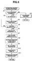
- controller 21 decides whether engine control unit 22 outputs a valve release command of one of valve units 100 to be checked.
- the routine proceeds to step S2.
- the routine proceeds to step S3.
- controller 21 commands driver circuit 23 to de-energize both of valve opening and closing electromagnets 10 and 11 of the checked valve unit 100. In reply to this commands, the checked valve unit 100 starts a free vibration.
- controller 21 detects the position z of movable member 6 on the basis of the signal form the position sensor 13 and stores the detected position z.
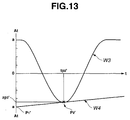
- controller 21 obtains the damping ratio ⁇ from a curve W2 which is obtained by connecting peaks P1 to Pn of movable member of the wave form W1. Since curve W2 is approximated by the following equation (3), the damping ratio ⁇ can be obtained from the information of at least two peaks. More specifically, by detecting time (moment) t and the position z of two peaks (P1 --- Pn) on the curve W2, the damping ratio can be obtained therefrom.
- a ⁇ exp(- ⁇ ⁇ ⁇ n ⁇ t) At In this equation (3), At is an amplitude at time t of the free vibration W1, and a is a maximum amplitude of the free vibration W1.
- controller 21 reads coolant temperature Tw.
- controller 21 commands drive circuit 23 to energize the valve opening electromagnet (VOE) 10 and to execute the landing control. That is, the routine jumps to the landing control routine shown by a flowchart of Fig. 10. After the execution of the landing control routine as to valve opening electromagnet 10, the routine proceeds to step S25.
- the landing control routine will be discussed later.
- controller 21 decides whether engine control unit 22 outputs a single resting command.
- the routine proceeds to step S52.
- the routine jumps to step S53.
Landscapes
- Engineering & Computer Science (AREA)
- Mechanical Engineering (AREA)
- General Engineering & Computer Science (AREA)
- Magnetically Actuated Valves (AREA)
- Valve Device For Special Equipments (AREA)
- Electromagnets (AREA)
Abstract
Description
When
In order to cancel this energy loss and to maintain the normal valve operation,
By de-energizing

When the decision at step S1 is affirmative, the routine proceeds to step S2. When the decision at step S1 is negative, the routine proceeds to step S3.
At step S7,
This step S9 constitutes a control parameter setting means.
Claims (13)
- A valve control system comprising:an electromagnetic valve unit comprisinga valve,a pair of electromagnets arranged inspaced relationship from one another in axialalignment with the valve so as to form a space,a movable member axially movably disposed in the space between the electromagnets, themovable member being interlocked with the valve,a pair of springs biasing the movable member so as to locate the movable member at an intermediate portion of the space when both of the electromagnets are de-energized; anda controller connected to said electromagnetic valve unit, said controller energizing and de-energizing each of said electromagnets to reciprocatingly displace the valve,said controller being arranged to detect a characteristic of a free vibration of a vibration system in said electromagnetic valve unit when both electromagnets are de-energized, and to estimate at least one of a friction quantity and a spring constant of the vibration system on the basis of the detected characteristic of the free vibration.
- The control system as claimed in claim 1,
wherein said controller controls electric current to be supplied to electromagnets to control the operation of the valve. - The control system as claimed in claim 1, wherein said controller controls electric current to be supplied to electromagnets based on the estimated characteristic of the vibration system of said valve unit.
- The control system as claimed in claim 1,
wherein said controller detects an actual damping ratio of the vibration system as the characteristic of the vibration system. - The control system as claimed in claim 1,
wherein said controller detects one of a cycle and a frequency of the free vibration as a characteristic. - The control system as claimed in claim 1,
wherein said controller generates the free vibration of the vibration system by de-energizing both of the electromagnets when said electromagnetic valve unit is put in a stopped condition. - The control system as claimed in claim 1,
wherein said controller generates the free vibration by de-energizing the electromagnet, which is of said electromagnetic valve unit adapted to one of the plurality of valves and which has been energized to keep the valve in a close condition, when the control system is adapted to control intake and exhaust valves of an internal combustion engine and when a plurality of intake valves or a plurality of exhaust valves are provided to each cylinder of the engine. - The control system as claimed in claim 3,
wherein said controller determines a control parameter employed for controlling the electric current to be supplied to said electromagnets, on the basis of at least one of the friction quantity and the spring constant. - The control system as claimed in claim 1,
wherein said controller detects a temperature indicative of a temperature of lubrication oil for the engine, and said controller stores the estimated friction quantity with the temperature at the estimated condition. - The control system as claimed in claim 9,
wherein said controller determines a control parameter employed for controlling electric current to be supplied to said electromagnets, on the basis of at the friction quantity stored in said controller. - An engine valve control system for electromagnetically controlling each of intake and exhaust valves of an internal combustion engine, said valve control system comprising:
an electromagnetic valve unit comprisinga pair of electromagnets arranged inspaced relationship from one another in axialalignment with the valve so as to form a space,a movable member axially movably disposed in the space between the electromagnets, the movable member being contacted with the valve,a pair of springs biasing the movable member so as to locate the movable member at an intermediate portion of the space when both of the electromagnets are de-energized; anda controller connected to said electromagnetic valve unit, said controller detecting a characteristic of a free vibration of a vibration system in said electromagnetic valve unit when both electromagnets are de-energized, said controller estimating at least one of a friction quantity and a spring constant of the vibration system on the basis of the detected characteristic of the free vibration, said controller controlling said electromagnetic valve unit on the basis of a control parameter determined by one of the estimated friction quantity and the estimated spring constant so as to reciprocatingly displace the valve between an opening state and a closing state. - A control system for controlling an electromagnetic valve unit, the electromagnetic valve unit comprising a valve, a pair of electromagnets arranged in spaced relationship from one another in axial alignment with the valve so as to form a space, a movable member axially movably disposed in the space between the electromagnets while being interlocked with the valve, and a pair of springs biasing the movable member so as to locate the movable member at an intermediate portion of the space when both of the electromagnets are de-energized, the control system comprising;free-vibration characteristic detecting means that detects a characteristic of a free vibration of a vibration system in the electromagnetic valve unit when both electromagnets are de-energized;vibration-condition estimating means that estimates at least one of a friction quantity and a spring constant of the vibration system on the basis of the detected characteristic of the free vibration; andcontrolling means controlling electric current supplied to the electromagnets based on the estimated one of the friction quantity and the spring constant to reciprocatingly displace the valve.
- A method for controlling an electromagnetic valve unit, the electromagnetic valve unit being arranged to operate a valve by electromagnetically controlling a pair of electromagnets so as to displace a movable member disposed in a space between the electromagnets which receiving biasing force of a pair of springs, the method comprising:detecting a characteristic of a free vibration of a vibration system in the electromagnetic valve unit when both electromagnets are de-energized; andestimating at least one of a friction quantity and a spring constant of the vibration system on the basis of the detected characteristic of the free vibration.
Applications Claiming Priority (2)
| Application Number | Priority Date | Filing Date | Title |
|---|---|---|---|
| JP2000166532A JP3617413B2 (en) | 2000-06-02 | 2000-06-02 | Control device for electromagnetically driven valve |
| JP2000166532 | 2000-06-02 |
Publications (3)
| Publication Number | Publication Date |
|---|---|
| EP1160422A2 true EP1160422A2 (en) | 2001-12-05 |
| EP1160422A3 EP1160422A3 (en) | 2003-05-14 |
| EP1160422B1 EP1160422B1 (en) | 2005-02-09 |
Family
ID=18669832
Family Applications (1)
| Application Number | Title | Priority Date | Filing Date |
|---|---|---|---|
| EP01113312A Expired - Lifetime EP1160422B1 (en) | 2000-06-02 | 2001-05-31 | Control system of electromagnetically operated valve |
Country Status (4)
| Country | Link |
|---|---|
| US (1) | US6412456B2 (en) |
| EP (1) | EP1160422B1 (en) |
| JP (1) | JP3617413B2 (en) |
| DE (1) | DE60108806T2 (en) |
Cited By (2)
| Publication number | Priority date | Publication date | Assignee | Title |
|---|---|---|---|---|
| EP1344902A3 (en) * | 2002-03-11 | 2007-09-26 | Toyota Jidosha Kabushiki Kaisha | Electromagnetically driven valve control apparatus |
| EP1455058A3 (en) * | 2003-03-05 | 2008-10-15 | Toyota Jidosha Kabushiki Kaisha | Electromagnetic valve drive system and method |
Families Citing this family (4)
| Publication number | Priority date | Publication date | Assignee | Title |
|---|---|---|---|---|
| US6536387B1 (en) * | 2001-09-27 | 2003-03-25 | Visteon Global Technologies, Inc. | Electromechanical engine valve actuator system with loss compensation controller |
| US6681728B2 (en) * | 2001-11-05 | 2004-01-27 | Ford Global Technologies, Llc | Method for controlling an electromechanical actuator for a fuel air charge valve |
| SE529328C2 (en) * | 2005-11-15 | 2007-07-10 | Johan Stenberg | Control system and method for controlling electromagnetically driven pumps |
| US20140219634A1 (en) | 2013-02-05 | 2014-08-07 | Redux, Inc. | Video preview creation based on environment |
Family Cites Families (10)
| Publication number | Priority date | Publication date | Assignee | Title |
|---|---|---|---|---|
| DE3307683C1 (en) * | 1983-03-04 | 1984-07-26 | Klöckner, Wolfgang, Dr., 8033 Krailling | Method for activating an electromagnetic actuator and device for carrying out the method |
| DE3810194C1 (en) * | 1988-03-25 | 1989-08-24 | Daimler-Benz Aktiengesellschaft, 7000 Stuttgart, De | |
| DE19526848B4 (en) * | 1995-07-22 | 2008-04-30 | Fev Motorentechnik Gmbh | Method for throttle-free load control of a reciprocating internal combustion engine with variable controllable gas exchange valves |
| JPH09317419A (en) * | 1996-05-28 | 1997-12-09 | Toyota Motor Corp | Abnormality detection method for electromagnetically driven valve for intake and exhaust |
| DE19623698A1 (en) * | 1996-06-14 | 1997-12-18 | Fev Motorentech Gmbh & Co Kg | Control of piston IC engine valve actuator |
| DE19640659B4 (en) * | 1996-10-02 | 2005-02-24 | Fev Motorentechnik Gmbh | Method for actuating an electromagnetic actuator influencing the coil current during the armature movement |
| US6041667A (en) * | 1997-07-31 | 2000-03-28 | Fev Motorentechnik Gmbh & Co. Kg | Method of operating an electromagnetic actuator with consideration of the armature motion |
| DE19739840C2 (en) * | 1997-09-11 | 2002-11-28 | Daimler Chrysler Ag | Method for controlling an electromagnetically actuated actuating device, in particular a valve for internal combustion engines |
| JP3877851B2 (en) | 1997-11-27 | 2007-02-07 | 株式会社日本自動車部品総合研究所 | Solenoid valve drive |
| JP3629362B2 (en) * | 1998-03-04 | 2005-03-16 | 愛三工業株式会社 | Driving method of electromagnetic valve for driving engine valve |
-
2000
- 2000-06-02 JP JP2000166532A patent/JP3617413B2/en not_active Expired - Fee Related
-
2001
- 2001-05-15 US US09/854,480 patent/US6412456B2/en not_active Expired - Lifetime
- 2001-05-31 EP EP01113312A patent/EP1160422B1/en not_active Expired - Lifetime
- 2001-05-31 DE DE60108806T patent/DE60108806T2/en not_active Expired - Lifetime
Cited By (2)
| Publication number | Priority date | Publication date | Assignee | Title |
|---|---|---|---|---|
| EP1344902A3 (en) * | 2002-03-11 | 2007-09-26 | Toyota Jidosha Kabushiki Kaisha | Electromagnetically driven valve control apparatus |
| EP1455058A3 (en) * | 2003-03-05 | 2008-10-15 | Toyota Jidosha Kabushiki Kaisha | Electromagnetic valve drive system and method |
Also Published As
| Publication number | Publication date |
|---|---|
| JP3617413B2 (en) | 2005-02-02 |
| DE60108806D1 (en) | 2005-03-17 |
| DE60108806T2 (en) | 2005-07-07 |
| US20020011224A1 (en) | 2002-01-31 |
| US6412456B2 (en) | 2002-07-02 |
| EP1160422A3 (en) | 2003-05-14 |
| EP1160422B1 (en) | 2005-02-09 |
| JP2001349463A (en) | 2001-12-21 |
Similar Documents
| Publication | Publication Date | Title |
|---|---|---|
| EP1077313B1 (en) | Apparatus for controlling electromagnetically powered engine valve | |
| US6044814A (en) | Electromagnetically driven valve control apparatus and method for an internal combustion engine | |
| JP2000049012A (en) | Method for controlling the movement of an armature of an electromagnetic actuator | |
| US6588385B2 (en) | Engine valve drive control apparatus and method | |
| US6427971B1 (en) | System for controlling electromagnetically actuated valve | |
| JP2001515984A (en) | Adjustment operation device operated electromagnetically and method of operating the adjustment operation device | |
| EP1160423B1 (en) | Control system for controlling an electromagnetic valve unit | |
| EP1211389B1 (en) | An electromagnetic valve controller | |
| JP2001023818A (en) | A method for adjusting the collision speed of a movable piece of an electromagnetic actuator by adjustment based on the characteristic curve of energization | |
| EP1160422B1 (en) | Control system of electromagnetically operated valve | |
| EP1052380B1 (en) | Electromagnetic valve drive and method for controlling same | |
| US6997146B2 (en) | Start control method and apparatus for solenoid-operated valves of internal combustion engine | |
| US20020126434A1 (en) | Electromagnetic actuator controller | |
| EP1162349B1 (en) | Apparatus and method for controlling electromagnetically operable engine valve assembly | |
| JP3614092B2 (en) | Valve clearance estimation device and control device for electromagnetically driven valve | |
| JP4089614B2 (en) | Variable feedback gain energization control method for electromagnetically driven valve | |
| JP2002054759A (en) | Control device for electromagnetically driven valve | |
| JP3424426B2 (en) | Electromagnetic valve drive for internal combustion engine | |
| JP4045858B2 (en) | Start-up control device for electromagnetically driven valve for internal combustion engine | |
| JP2001221022A (en) | Control device for electromagnetically driven valve | |
| US20090178631A1 (en) | Method of controlling an actuator having a movable member with positional feedback control | |
| JP2001015329A (en) | Valve clearance estimation device for electromagnetically driven valve | |
| JP2001324046A (en) | Control device for electromagnetically driven valve | |
| JP2002081569A (en) | Control device for electromagnetically driven valve |
Legal Events
| Date | Code | Title | Description |
|---|---|---|---|
| PUAI | Public reference made under article 153(3) epc to a published international application that has entered the european phase |
Free format text: ORIGINAL CODE: 0009012 |
|
| 17P | Request for examination filed |
Effective date: 20010531 |
|
| AK | Designated contracting states |
Kind code of ref document: A2 Designated state(s): AT BE CH CY DE DK ES FI FR GB GR IE IT LI LU MC NL PT SE TR |
|
| AX | Request for extension of the european patent |
Free format text: AL;LT;LV;MK;RO;SI |
|
| PUAL | Search report despatched |
Free format text: ORIGINAL CODE: 0009013 |
|
| AK | Designated contracting states |
Designated state(s): AT BE CH CY DE DK ES FI FR GB GR IE IT LI LU MC NL PT SE TR |
|
| AX | Request for extension of the european patent |
Extension state: AL LT LV MK RO SI |
|
| RIC1 | Information provided on ipc code assigned before grant |
Ipc: 7F 02D 41/22 B Ipc: 7F 01L 9/04 A Ipc: 7F 16K 31/06 B Ipc: 7H 01F 7/16 B |
|
| 17Q | First examination report despatched |
Effective date: 20031211 |
|
| AKX | Designation fees paid |
Designated state(s): DE FR GB |
|
| GRAP | Despatch of communication of intention to grant a patent |
Free format text: ORIGINAL CODE: EPIDOSNIGR1 |
|
| GRAS | Grant fee paid |
Free format text: ORIGINAL CODE: EPIDOSNIGR3 |
|
| GRAA | (expected) grant |
Free format text: ORIGINAL CODE: 0009210 |
|
| AK | Designated contracting states |
Kind code of ref document: B1 Designated state(s): DE FR GB |
|
| REG | Reference to a national code |
Ref country code: GB Ref legal event code: FG4D |
|
| REG | Reference to a national code |
Ref country code: IE Ref legal event code: FG4D |
|
| REF | Corresponds to: |
Ref document number: 60108806 Country of ref document: DE Date of ref document: 20050317 Kind code of ref document: P |
|
| PLBE | No opposition filed within time limit |
Free format text: ORIGINAL CODE: 0009261 |
|
| STAA | Information on the status of an ep patent application or granted ep patent |
Free format text: STATUS: NO OPPOSITION FILED WITHIN TIME LIMIT |
|
| ET | Fr: translation filed | ||
| 26N | No opposition filed |
Effective date: 20051110 |
|
| PGFP | Annual fee paid to national office [announced via postgrant information from national office to epo] |
Ref country code: GB Payment date: 20140528 Year of fee payment: 14 |
|
| PGFP | Annual fee paid to national office [announced via postgrant information from national office to epo] |
Ref country code: DE Payment date: 20140528 Year of fee payment: 14 Ref country code: FR Payment date: 20140509 Year of fee payment: 14 |
|
| REG | Reference to a national code |
Ref country code: DE Ref legal event code: R119 Ref document number: 60108806 Country of ref document: DE |
|
| GBPC | Gb: european patent ceased through non-payment of renewal fee |
Effective date: 20150531 |
|
| REG | Reference to a national code |
Ref country code: FR Ref legal event code: ST Effective date: 20160129 |
|
| PG25 | Lapsed in a contracting state [announced via postgrant information from national office to epo] |
Ref country code: DE Free format text: LAPSE BECAUSE OF NON-PAYMENT OF DUE FEES Effective date: 20151201 Ref country code: GB Free format text: LAPSE BECAUSE OF NON-PAYMENT OF DUE FEES Effective date: 20150531 |
|
| PG25 | Lapsed in a contracting state [announced via postgrant information from national office to epo] |
Ref country code: FR Free format text: LAPSE BECAUSE OF NON-PAYMENT OF DUE FEES Effective date: 20150601 |