EP1160028A1 - Continuous casting method with rolls and relative device - Google Patents
Continuous casting method with rolls and relative device Download PDFInfo
- Publication number
- EP1160028A1 EP1160028A1 EP01112792A EP01112792A EP1160028A1 EP 1160028 A1 EP1160028 A1 EP 1160028A1 EP 01112792 A EP01112792 A EP 01112792A EP 01112792 A EP01112792 A EP 01112792A EP 1160028 A1 EP1160028 A1 EP 1160028A1
- Authority
- EP
- European Patent Office
- Prior art keywords
- rolls
- strip
- shearing means
- shearing
- provides
- Prior art date
- Legal status (The legal status is an assumption and is not a legal conclusion. Google has not performed a legal analysis and makes no representation as to the accuracy of the status listed.)
- Withdrawn
Links
- 238000000034 method Methods 0.000 title claims abstract description 24
- 238000009749 continuous casting Methods 0.000 title claims abstract description 13
- 238000010008 shearing Methods 0.000 claims abstract description 53
- 239000002184 metal Substances 0.000 claims abstract description 29
- 229910052751 metal Inorganic materials 0.000 claims abstract description 29
- 238000005520 cutting process Methods 0.000 claims description 12
- 239000011261 inert gas Substances 0.000 claims description 5
- 230000009471 action Effects 0.000 claims description 4
- QVGXLLKOCUKJST-UHFFFAOYSA-N atomic oxygen Chemical compound [O] QVGXLLKOCUKJST-UHFFFAOYSA-N 0.000 claims description 3
- 239000001301 oxygen Substances 0.000 claims description 3
- 229910052760 oxygen Inorganic materials 0.000 claims description 3
- 230000000284 resting effect Effects 0.000 claims description 2
- 239000007789 gas Substances 0.000 claims 1
- 238000005266 casting Methods 0.000 description 12
- 238000000605 extraction Methods 0.000 description 11
- 229910000831 Steel Inorganic materials 0.000 description 10
- 239000010959 steel Substances 0.000 description 10
- 238000001816 cooling Methods 0.000 description 3
- XEEYBQQBJWHFJM-UHFFFAOYSA-N Iron Chemical compound [Fe] XEEYBQQBJWHFJM-UHFFFAOYSA-N 0.000 description 2
- 239000007788 liquid Substances 0.000 description 2
- 238000013021 overheating Methods 0.000 description 2
- 230000008569 process Effects 0.000 description 2
- 238000005096 rolling process Methods 0.000 description 2
- 238000007789 sealing Methods 0.000 description 2
- 238000009966 trimming Methods 0.000 description 2
- 229910001208 Crucible steel Inorganic materials 0.000 description 1
- 238000007792 addition Methods 0.000 description 1
- 229910045601 alloy Inorganic materials 0.000 description 1
- 239000000956 alloy Substances 0.000 description 1
- 238000010924 continuous production Methods 0.000 description 1
- 230000001419 dependent effect Effects 0.000 description 1
- 238000007654 immersion Methods 0.000 description 1
- 238000009434 installation Methods 0.000 description 1
- 230000002452 interceptive effect Effects 0.000 description 1
- 229910052742 iron Inorganic materials 0.000 description 1
- 229910001338 liquidmetal Inorganic materials 0.000 description 1
- 230000001050 lubricating effect Effects 0.000 description 1
- 238000004519 manufacturing process Methods 0.000 description 1
- 239000000463 material Substances 0.000 description 1
- 230000005499 meniscus Effects 0.000 description 1
- 239000000203 mixture Substances 0.000 description 1
- 238000012986 modification Methods 0.000 description 1
- 230000004048 modification Effects 0.000 description 1
- 230000003647 oxidation Effects 0.000 description 1
- 238000007254 oxidation reaction Methods 0.000 description 1
- 238000003825 pressing Methods 0.000 description 1
- 230000002035 prolonged effect Effects 0.000 description 1
- 239000011819 refractory material Substances 0.000 description 1
- 238000007493 shaping process Methods 0.000 description 1
- 238000011144 upstream manufacturing Methods 0.000 description 1
- 239000002699 waste material Substances 0.000 description 1
- XLYOFNOQVPJJNP-UHFFFAOYSA-N water Substances O XLYOFNOQVPJJNP-UHFFFAOYSA-N 0.000 description 1
Images


Classifications
-
- B—PERFORMING OPERATIONS; TRANSPORTING
- B22—CASTING; POWDER METALLURGY
- B22D—CASTING OF METALS; CASTING OF OTHER SUBSTANCES BY THE SAME PROCESSES OR DEVICES
- B22D11/00—Continuous casting of metals, i.e. casting in indefinite lengths
- B22D11/06—Continuous casting of metals, i.e. casting in indefinite lengths into moulds with travelling walls, e.g. with rolls, plates, belts, caterpillars
- B22D11/0622—Continuous casting of metals, i.e. casting in indefinite lengths into moulds with travelling walls, e.g. with rolls, plates, belts, caterpillars formed by two casting wheels
- B22D11/0625—Continuous casting of metals, i.e. casting in indefinite lengths into moulds with travelling walls, e.g. with rolls, plates, belts, caterpillars formed by two casting wheels the two casting wheels being immersed in a molten metal bath and drawing out upwardly the casting strip
-
- B—PERFORMING OPERATIONS; TRANSPORTING
- B22—CASTING; POWDER METALLURGY
- B22D—CASTING OF METALS; CASTING OF OTHER SUBSTANCES BY THE SAME PROCESSES OR DEVICES
- B22D11/00—Continuous casting of metals, i.e. casting in indefinite lengths
- B22D11/12—Accessories for subsequent treating or working cast stock in situ
- B22D11/126—Accessories for subsequent treating or working cast stock in situ for cutting
-
- B—PERFORMING OPERATIONS; TRANSPORTING
- B21—MECHANICAL METAL-WORKING WITHOUT ESSENTIALLY REMOVING MATERIAL; PUNCHING METAL
- B21B—ROLLING OF METAL
- B21B1/00—Metal-rolling methods or mills for making semi-finished products of solid or profiled cross-section; Sequence of operations in milling trains; Layout of rolling-mill plant, e.g. grouping of stands; Succession of passes or of sectional pass alternations
- B21B1/46—Metal-rolling methods or mills for making semi-finished products of solid or profiled cross-section; Sequence of operations in milling trains; Layout of rolling-mill plant, e.g. grouping of stands; Succession of passes or of sectional pass alternations for rolling metal immediately subsequent to continuous casting
- B21B1/463—Metal-rolling methods or mills for making semi-finished products of solid or profiled cross-section; Sequence of operations in milling trains; Layout of rolling-mill plant, e.g. grouping of stands; Succession of passes or of sectional pass alternations for rolling metal immediately subsequent to continuous casting in a continuous process, i.e. the cast not being cut before rolling
Definitions
- This invention concerns a continuous casting method with rolls and the relative device, used in the field of continuous casting to cast steel strips by means of a pair of counter-rotating rolls.
- the invention concerns a casting method with rolls with upward extraction wherein there are shearing means provided associated with the ends of the rolls and able to define the width and finish of the edges of the strip in a substantially continuous manner.
- the state of the art includes the technique of casting with rolls and with upward extraction wherein a pair of counter-rotating cooled rolls is partly immersed in a container into which the molten metal is fed.
- This casting technique with rolls and upward extraction has considerable potential in the production of high quality strips: it makes possible to guarantee high productivity, limited costs and savings in the labor force compared with traditional techniques.
- the purpose of the invention is to obtain a continuous casting method and device with counter-rotating rolls and upward extraction which on the one hand solves the problem of lateral containment of the metal in correspondence with the ends of the rolls, and in which on the other hand the procedure of the final shaping of the strip is optimized, at least in terms of width and edge finishing.
- the invention provides to use a substantially conventional casting device, comprising at least a container to contain the molten metal inside which two counter-rotating rolls, cooled and facing each other, are partly immersed, and define the gap through which the cast product is extracted.
- the device comprises shearing means arranged in cooperation with the periphery of the rolls, at least a first shearing mean being associated with one end of the rolls and a second shearing mean being associated with the other end of the rolls.
- the shearing means are able to section the strip, partly solidified on the surfaces of the rolls, in correspondence with its edges so as to define the width thereof.
- the material sectioned in correspondence with the edges by the shearing means falls back into the container and returns to the molten state, and is therefore immediately available for the continuation of the casting process.
- the shearing means in a preferential embodiment, can cooperate directly with the ends of the rolls and use the ends as a reference and positioning element.
- the width of the strip extracted always corresponds substantially to the length of the rolls used.
- the shearing means are located above and in an inner position with respect to the ends of the rolls, and have at their lower part a shaped conformation able to cooperate with the curved cavity defined by the coupled faces of the rolls.
- the strip extracted can have a desired width, less than the length of the casting rolls.
- the shearing means can translate along the rolls, parallel to their axis, in order to define on each occasion the width of the strip to be cast.
- the shearing means can be of any suitable type.
- the shearing means are of the type able to define a cutting edge which already has the finished characteristics required to the finished product.
- a preferential but non-restrictive embodiment provides substantially fixed shearing blades, arranged orthogonal or inclined with respect to the axis of extraction of the cast strip.
- Another embodiment provides to use rotary shearing blades.
- the shearing means are associated with cooling systems so as to prevent overheating thereof, due to the continuous contact with the steel solidifying on the surfaces of the rolls.
- the end walls of the rolls comprise, or cooperate with, means able to prevent the partly solidified steel from sticking to said walls, making then difficult for the shearing means to remove the steel.
- said means consist of lubricating products which are applied on the walls and prevent the steel from sticking thereto.
- said means consist of pneumatic elements able to blow inert gas through orifices in the walls; the jets of inert gas prevent the solidified metal from sticking to the walls and encourage the metal to fall and be subsequently removed by the shearing means.
- said means consist of elements able to generate high frequency vibrations in said lateral walls.
- said means consist of elements able to heat and re-melt the solidified steel stuck to the lateral walls.
- said means consist of coils able to generate a repulsive magnetic field on the liquid steel.
- Fig. 1 the reference number 38 denotes generally a line to produce strip 13 obtained starting from a continuous casting device with rolls, denoted by the reference number 10.
- the device 10 comprises a pair of counter-rotating rolls 11, arranged with their respective axes 111 parallel and in an adjacent position to define a gap 12 through which the strip 13 to be produced is extracted upward.
- the distance between the axes 111 of the rolls 11 can be adjusted so as to define the desired thickness of the strip 13 produced by the device 10.
- the preferential, though not restrictive, value of the thickness of the strip 13 emerging from the device 10 is between 0.5 and 10 mm.
- the rolling line comprises a cropping shears 15 which can also be used as an emergency shears, a descaling assembly 16, between 1 and 3 finishing stands 17, a cooling assembly 18, a flying shears 19 and a carousel coiler 20.
- the continuous casting device 10 consists of a container 21 suitable to contain the molten metal 22, inside which the metal is poured through a measuring tundish 23 fed by a ladle 24.
- the ladle 24 is associated with conventional handling and discharge means 25 mounted on a turret 26.
- the container 21 advantageously has a bottom and lateral walls made of and/or at least partly lined with refractory material.
- the container 21 is associated with a sealing cover 36 which defines a substantially closed environment inside which an inert atmosphere is created which prevents any possible phenomenon of oxidation of the molten or partly solidified metal.
- the cover 36 can cover the rolls 11 totally or only partly, as in Fig. 3b.
- the molten metal 22 can consist of any type of steel, iron, alloys or other suitable metal, and the feed from the tundish 23 may be governed by appropriate means able to ensure that a substantially constant level is maintained in the container 21.
- the loading zone of the metal 22 can be separated from the zone of the container 21 beneath the rolls 11 by dividing walls, so that the unloading of the molten metal 22 does not generate any turbulence in correspondence with the meniscus.
- shearing means 27 one for each side on the length of the rolls 11, the function of which is to section that part of the forming strip 13 which exceeds the length of the rolls 11.
- the two semi-skins are formed freely on the surface of the relative rolls 11 without being confined laterally until, in correspondence with the line of contact, or kissing point, 30, they form the strip 13 due to reciprocal sticking, which is then extracted upward.
- the strip 13 Before being discharged from the rolls 11, just above the line of contact 30, the strip 13 is subjected to sectioning by the shearing means 27, which act on the edges of the strip 13 in correspondence with the ends of the rolls 11.
- Said sectioning action may take place in a zone below the highest point of the circular surface of the rolls 11, or above said highest point (Fig. 3c).
- the shearing means 27 are able to remove lateral parts 37 of solidified metal which exceed the length of the rolls 11.
- the lateral parts 37, thrust by the pressing action exerted in correspondence with the kissing point, are separated from the central body of the strip 13 and fall back into the container 21 (Fig. 6), melt again and mix with the molten metal 22 contained in said container 21.
- the shearing means 27 therefore carry out two functions simultaneously and continuously: they define the width of the strip 13 extracted and contain it laterally.
- the shearing means 27 can have a further function, which is to finish the edges; this obviates the need of appropriate subsequent processing upstream or downstream of the finishing stands 17, and therefore the relative equipment does not need to be installed, and the waste deriving from said trimming operations carried out downstream is eliminated.
- the shearing means 27 consist of fixed blades 28 with their respective cutting edge 29 substantially orthogonal to the edge of the strip 13 emerging from the rolls 11.
- the shearing means 27 consist of fixed blades 128 with their cutting edge 129 inclined with respect to the edge of the strip 13.
- the shearing means 27 consist of a pair of circular rotary blades 228 associated with an axial drive shaft, while in the further variant shown in Fig. 3c, the shearing means 27 consist of two pairs of rotary blades 228 arranged above the rolls 11.
- the shearing means 27 can be of the vibrating type, in order to encourage the sectioning operation. Moreover, the shearing means 27 are associated with appropriate cooling systems, for example with circulating water, jets of air or other types, which prevent them from overheating caused by their prolonged contact with the metal being extracted.
- the shearing means 27 comprise laser devices, or oxygen lance cutting devices, or other systems.
- the shearing means 27 are arranged resting on the ends of the rolls 11, which thus perform a reference function, and the width of the strip 13 extracted is substantially equal to the length of the rolls 11.
- the shearing means 27 cooperate from above and in contact with the surface of the rolls 11, so as to ensure in any case the hydraulic seal of the molten metal 22; moreover, they can slide axially along the rolls 11 so as to define on each occasion a desired width of the strip 13 to be extracted.
- the shearing means 27 can be associated with sharpening devices which intervene periodically to restore the cutting edge after a certain period of use.
- the casting device 10 comprises anti-sticking means associated with the lateral walls 33.
- the anti-sticking means consist of a high-frequency mechanical transducer 31 installed inside each roll 11 in a compartment 32 made adjacent to the end of the roll 11.
- the transducer 31 can be of any conventional type, for example piezoelectric, magnetostrictive, or any other type suitable for the purpose.
- the anti-sticking means comprise electromagnetic devices 34 installed in said compartment 32 adjacent to the wall 33 and able to generate a repulsive magnetic field on the liquid metal which prevents the solidified metal from sticking to the sides of the wall 33 and causes it to re-melt.
- the anti-sticking means consist of a pneumatic system 35 arranged inside said compartment 32 and able to deliver an inert gas through a plurality of holes or slits, not shown here, made in the wall 33 and/or in the curved wall of the compartment 32.
- the inert gas substantially prevents the solidified metal from coming into contact with and sticking to the wall 33 immersed in the liquid bath 22.
Landscapes
- Engineering & Computer Science (AREA)
- Mechanical Engineering (AREA)
- Continuous Casting (AREA)
- Metal Rolling (AREA)
Abstract
Description
- This invention concerns a continuous casting method with rolls and the relative device, used in the field of continuous casting to cast steel strips by means of a pair of counter-rotating rolls.
- To be more exact, the invention concerns a casting method with rolls with upward extraction wherein there are shearing means provided associated with the ends of the rolls and able to define the width and finish of the edges of the strip in a substantially continuous manner.
- In the field of continuous casting of plane products such as strips, the state of the art includes the technique of casting with rolls and with upward extraction wherein a pair of counter-rotating cooled rolls is partly immersed in a container into which the molten metal is fed.
- The rolls, rotating in a reciprocally opposite direction, cause a solidified skin to form on their respective surfaces; these skins join together and form the product which is extracted upward.
- This casting technique with rolls and upward extraction has considerable potential in the production of high quality strips: it makes possible to guarantee high productivity, limited costs and savings in the labor force compared with traditional techniques.
- With the product extracted upward it is possible to obtain higher casting speeds, up to 4 metres per second and more, since the angle of immersion and therefore the contact surface between the steel and the roll can be as much as twice what can be obtained with a downward extraction of the metal. Moreover, with this solution it is possible to solve the problem of lateral containment of the molten steel in proximity or in correspondence with the ends of the rolls.
- All attempts to use sealing means of a mechanical or magnetic type in plants with a downward extraction have met with considerable problems, both economical and functional-technological, which have often made impossible to propose such a solution.
- In plants with an upward extraction, the lateral containment made with magnetic means appears potentially more effective and entails fewer problems and difficulties, both technological and with regard to the process.
- However, there has been a manifest need to find solutions which allow to further improve the efficiency of the process, increasing productivity and the speed of extraction while maintaining high quality of the cast product, and optimizing in the whole the functioning and the plant costs of the whole casting line.
- The present Applicant has devised, tested and embodied this invention in the light of this necessity, and to obtain further advantages as will be shown hereafter.
- The invention is set forth and characterized in the respective main claims, while the dependent claims describe other characteristics of the main embodiment.
- The purpose of the invention is to obtain a continuous casting method and device with counter-rotating rolls and upward extraction which on the one hand solves the problem of lateral containment of the metal in correspondence with the ends of the rolls, and in which on the other hand the procedure of the final shaping of the strip is optimized, at least in terms of width and edge finishing.
- This purpose is obtained with an economical, functional and simple solution which can be applied substantially in every type of installation.
- The invention provides to use a substantially conventional casting device, comprising at least a container to contain the molten metal inside which two counter-rotating rolls, cooled and facing each other, are partly immersed, and define the gap through which the cast product is extracted.
- According to the invention, the device comprises shearing means arranged in cooperation with the periphery of the rolls, at least a first shearing mean being associated with one end of the rolls and a second shearing mean being associated with the other end of the rolls.
- The shearing means are able to section the strip, partly solidified on the surfaces of the rolls, in correspondence with its edges so as to define the width thereof. The material sectioned in correspondence with the edges by the shearing means falls back into the container and returns to the molten state, and is therefore immediately available for the continuation of the casting process.
- The shearing means, in a preferential embodiment, can cooperate directly with the ends of the rolls and use the ends as a reference and positioning element.
- In this case, the width of the strip extracted always corresponds substantially to the length of the rolls used.
- In another solution, the shearing means are located above and in an inner position with respect to the ends of the rolls, and have at their lower part a shaped conformation able to cooperate with the curved cavity defined by the coupled faces of the rolls. In this case, the strip extracted can have a desired width, less than the length of the casting rolls.
- In another embodiment again, the shearing means can translate along the rolls, parallel to their axis, in order to define on each occasion the width of the strip to be cast.
- The shearing means can be of any suitable type.
- In a preferential embodiment, the shearing means are of the type able to define a cutting edge which already has the finished characteristics required to the finished product.
- In this embodiment therefore, it is possible to eliminate, or at least reduce, further trimming and/or finishing operations and the relative equipment, downstream of the continuous casting machine.
- A preferential but non-restrictive embodiment provides substantially fixed shearing blades, arranged orthogonal or inclined with respect to the axis of extraction of the cast strip. Another embodiment provides to use rotary shearing blades.
- Further alternative embodiments which can be used in the field of the invention provide laser systems, oxygen lance cutting systems or other systems; one or other of the shearing systems is adopted according to the type of steel to be sheared, the productivity required and the level of finishing desired.
- The shearing means are associated with cooling systems so as to prevent overheating thereof, due to the continuous contact with the steel solidifying on the surfaces of the rolls.
- In one embodiment of the invention, the end walls of the rolls comprise, or cooperate with, means able to prevent the partly solidified steel from sticking to said walls, making then difficult for the shearing means to remove the steel.
- In a first embodiment, said means consist of lubricating products which are applied on the walls and prevent the steel from sticking thereto.
- In another embodiment, said means consist of pneumatic elements able to blow inert gas through orifices in the walls; the jets of inert gas prevent the solidified metal from sticking to the walls and encourage the metal to fall and be subsequently removed by the shearing means.
- In a further embodiment, said means consist of elements able to generate high frequency vibrations in said lateral walls. In another embodiment, said means consist of elements able to heat and re-melt the solidified steel stuck to the lateral walls.
- In yet another embodiment, said means consist of coils able to generate a repulsive magnetic field on the liquid steel.
- These and other characteristics of the invention will be clear from the following description of the preferred form of embodiment, given as a non-restrictive example with reference to the attached drawings wherein:
- Fig. 1
- shows schematically a line to produce strips and/or sheets adopting a continuous casting device with rolls according to the invention;
- Fig. 2a
- is a schematic transverse section of the continuous casting device according to the invention;
- Fig. 2b
- is a schematic view from above of Fig. 2a;
- Figs. 3a and 3b
- show two different embodiments of the device in Fig. 2a;
- Fig. 3c
- shows a variant of Figs. 3a, 3b;
- Fig. 4
- shows a longitudinal section of a detail of the casting device in Fig. 2a;
- Figs. 5a and 5b
- show different embodiments of the detail in Fig. 4;
- Fig. 6
- shows schematically a section from A to A of Fig. 2b.
- In Fig. 1 the
reference number 38 denotes generally a line to producestrip 13 obtained starting from a continuous casting device with rolls, denoted by thereference number 10. - The
device 10 comprises a pair of counter-rotating rolls 11, arranged with theirrespective axes 111 parallel and in an adjacent position to define agap 12 through which thestrip 13 to be produced is extracted upward. - The distance between the
axes 111 of therolls 11 can be adjusted so as to define the desired thickness of thestrip 13 produced by thedevice 10. - The preferential, though not restrictive, value of the thickness of the
strip 13 emerging from thedevice 10 is between 0.5 and 10 mm. - Downstream of the
device 10 there is an assembly ofrolls 14, used for extraction and possibly straightening purposes, through which thestrip 13 is progressively taken to a horizontal position to be then sent to the rolling line. - In this case, the rolling line comprises a cropping shears 15 which can also be used as an emergency shears, a
descaling assembly 16, between 1 and 3 finishing stands 17, a coolingassembly 18, a flying shears 19 and acarousel coiler 20. - The
continuous casting device 10 consists of acontainer 21 suitable to contain themolten metal 22, inside which the metal is poured through a measuringtundish 23 fed by aladle 24. Theladle 24 is associated with conventional handling and discharge means 25 mounted on aturret 26. - The
container 21 advantageously has a bottom and lateral walls made of and/or at least partly lined with refractory material. - The
container 21 is associated with a sealingcover 36 which defines a substantially closed environment inside which an inert atmosphere is created which prevents any possible phenomenon of oxidation of the molten or partly solidified metal. - The
cover 36 can cover therolls 11 totally or only partly, as in Fig. 3b. - The
molten metal 22 can consist of any type of steel, iron, alloys or other suitable metal, and the feed from thetundish 23 may be governed by appropriate means able to ensure that a substantially constant level is maintained in thecontainer 21. The loading zone of themetal 22 can be separated from the zone of thecontainer 21 beneath therolls 11 by dividing walls, so that the unloading of themolten metal 22 does not generate any turbulence in correspondence with the meniscus. - In the embodiment shown in Figs. 2a and 2b, in cooperation with the ends of the
rolls 11, there are shearingmeans 27, one for each side on the length of therolls 11, the function of which is to section that part of the formingstrip 13 which exceeds the length of therolls 11. - In other words, in the
device 10 it is provided that the two semi-skins are formed freely on the surface of the relative rolls 11 without being confined laterally until, in correspondence with the line of contact, or kissing point, 30, they form thestrip 13 due to reciprocal sticking, which is then extracted upward. - Before being discharged from the
rolls 11, just above the line ofcontact 30, thestrip 13 is subjected to sectioning by the shearing means 27, which act on the edges of thestrip 13 in correspondence with the ends of therolls 11. - Said sectioning action may take place in a zone below the highest point of the circular surface of the
rolls 11, or above said highest point (Fig. 3c). - The shearing means 27 are able to remove
lateral parts 37 of solidified metal which exceed the length of therolls 11. Thelateral parts 37, thrust by the pressing action exerted in correspondence with the kissing point, are separated from the central body of thestrip 13 and fall back into the container 21 (Fig. 6), melt again and mix with themolten metal 22 contained in saidcontainer 21. - The shearing means 27 therefore carry out two functions simultaneously and continuously: they define the width of the
strip 13 extracted and contain it laterally. - By means of an appropriate configuration and management, the shearing means 27 can have a further function, which is to finish the edges; this obviates the need of appropriate subsequent processing upstream or downstream of the finishing stands 17, and therefore the relative equipment does not need to be installed, and the waste deriving from said trimming operations carried out downstream is eliminated.
- These functions are performed continuously without interfering with the continuous process of casting and extraction, which can thus ensure very high productivity, up to 2 Mton per year, and extremely high casting speeds, up to 4 metres per second and more.
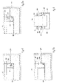
- In the embodiment shown in Figs. 2a and 2b, the shearing means 27 consist of fixed
blades 28 with theirrespective cutting edge 29 substantially orthogonal to the edge of thestrip 13 emerging from therolls 11. In the variant shown in Fig. 3a, the shearing means 27 consist of fixedblades 128 with theircutting edge 129 inclined with respect to the edge of thestrip 13. - In the other variant shown in Fig. 3b, the shearing means 27 consist of a pair of
circular rotary blades 228 associated with an axial drive shaft, while in the further variant shown in Fig. 3c, the shearing means 27 consist of two pairs ofrotary blades 228 arranged above therolls 11. - The shearing means 27 can be of the vibrating type, in order to encourage the sectioning operation. Moreover, the shearing means 27 are associated with appropriate cooling systems, for example with circulating water, jets of air or other types, which prevent them from overheating caused by their prolonged contact with the metal being extracted.
- According to other variants which are not shown here, the shearing means 27 comprise laser devices, or oxygen lance cutting devices, or other systems.
- In the embodiments shown in Figs. 3a and 3b, the shearing means 27 are arranged resting on the ends of the
rolls 11, which thus perform a reference function, and the width of thestrip 13 extracted is substantially equal to the length of therolls 11. - According to a variant which is not shown here, the shearing means 27 cooperate from above and in contact with the surface of the
rolls 11, so as to ensure in any case the hydraulic seal of themolten metal 22; moreover, they can slide axially along therolls 11 so as to define on each occasion a desired width of thestrip 13 to be extracted. - According to other variants which are not shown here, the shearing means 27 can be associated with sharpening devices which intervene periodically to restore the cutting edge after a certain period of use.
- To prevent the partly solidified metal from sticking to the
lateral walls 33 defined by the ends of therolls 11, and therefore to obviate the problem of removing it with the shearing means 27, thecasting device 10 comprises anti-sticking means associated with thelateral walls 33. - In the embodiment shown in Fig. 4, the anti-sticking means consist of a high-frequency
mechanical transducer 31 installed inside eachroll 11 in acompartment 32 made adjacent to the end of theroll 11. - The function of the
mechanical transducer 31, which in this case is represented by a spring with a relative oscillator element, is to keep thewalls 33 vibrating, preventing the solidified metal from sticking thereto and so facilitating the subsequent shearing operation. - The
transducer 31 can be of any conventional type, for example piezoelectric, magnetostrictive, or any other type suitable for the purpose. - According to the embodiment shown in Fig. 5a, the anti-sticking means comprise
electromagnetic devices 34 installed in saidcompartment 32 adjacent to thewall 33 and able to generate a repulsive magnetic field on the liquid metal which prevents the solidified metal from sticking to the sides of thewall 33 and causes it to re-melt. - In the further embodiment shown in Fig. 5b, the anti-sticking means consist of a
pneumatic system 35 arranged inside saidcompartment 32 and able to deliver an inert gas through a plurality of holes or slits, not shown here, made in thewall 33 and/or in the curved wall of thecompartment 32. - The inert gas substantially prevents the solidified metal from coming into contact with and sticking to the
wall 33 immersed in theliquid bath 22. - It is obvious that modifications and additions can be made to this invention, but these shall remain within the field and scope thereof.
Claims (25)
- Continuous casting method with rolls for plane products such as strips (13), wherein counter-rotating rolls (11) are partly immersed in a container (21) containing molten metal (22), said rolls (11) being arranged parallel and adjacent to define a gap (12) through which the strip (13) to be produced is extracted upward, said strip (13) being formed by the union of two semi-skins which are formed on the respective surfaces of said rolls (11) and are joined together in correspondence with a line of contact (30), the method being characterized in that it provides that shearing means (27), arranged substantially in cooperation with the periphery of said rolls (11), act on the sides of said strip (13) to define at least the width of said strip (13) extracted from said rolls (11).
- Method as in Claim 1, characterized in that it provides to position two of said shearing means (27) arranged separated on the length of the respective rolls (11) and with the respective cutting edges (28) arranged in a position of cooperation with said line of contact (30) of said two semi-skins.
- Method as in Claim 1, characterized in that it provides to position said shearing means (27) in contact with the respective ends of said rolls (11) to section the lateral parts (37) of the strip (13) which exceed the length of said rolls (11).
- Method as in Claim 1, characterized in that it provides to position said shearing means (27) above and in an inner position with respect to said ends of the rolls (11) so as to define a width of the strip (13) which is less than the length of said rolls (11).
- Method as in Claim 4, characterized in that it provides to translate said shearing means (27) along the rolls with the purpose of defining a variable width of the strip (13).
- Method as in Claim 1, characterized in that it provides to use shearing means (27) of the type able to define a cutting edge of the strip (13) which already has the finishing characteristics required to the finished product.
- Method as in Claim 1, characterized in that it provides to use fixed shearing means (27) of the mechanical type.
- Method as in Claim 1, characterized in that it provides to use rotary shearing means (27) of the mechanical type.
- Method as in Claim 7 or 8, characterized in that it provides to use shearing means (27) of the vibrating type.
- Method as in Claim 1, characterized in that it provides to use shearing means (27) of the laser type.
- Method as in Claim 1, characterized in that it provides to use anti-sticking means (31, 34, 35) arranged in cooperation with the ends of said rolls (11) and able to prevent the metal from sticking to the walls (33) of said rolls (11) to facilitate the subsequent shearing operation.
- Continuous casting device with rolls for plane products such as strips (13), comprising counter-rotating rolls (11) partly immersed in a container (21) containing molten metal (22), said rolls (11) being arranged parallel and adjacent to define a gap (12) through which the strip (13) to be produced is extracted upward, said strip (13) being formed by the union of two semi-skins which are formed on the respective surfaces of said rolls (11) and are joined together in correspondence with a line of contact (30), the device being characterized in that it comprises shearing means (27) arranged in cooperation with the periphery of said rolls (11) and able to perform a sectioning action on said strip (13) to define at least the width of said strip (13) extracted from said rolls (11).
- Device as in Claim 12, characterized in that said shearing means (27) have a cutting edge positioned at least partly between said line of contact (30) of the semi-skins and the highest end of said rolls (11).
- Device as in Claim 13, characterized in that said cutting edge (29) is arranged substantially orthogonal to the front edge of the strip (13) emerging from said rolls (11).
- Device as in Claim 13, characterized in that said cutting edge (129) is arranged inclined with respect to the front edge of the strip (13) emerging from said rolls (11).
- Device as in Claim 13, characterized in that said cutting edge is curved.
- Device as in Claim 12, characterized in that said shearing means (27) are of the laser type.
- Device as in Claim 12, characterized in that said shearing means (27) are of the oxygen lance type.
- Device as in Claim 12, characterized in that said shearing means (27) are arranged resting on the ends of the respective rolls (11) which perform a reference function for said means (27).
- Device as in Claim 12, characterized in that said shearing means (27) are able to slide along the rolls (11) parallel to their longitudinal axis and have at their lower part a shaped conformation able to cooperate with the curved cavity defined by the surfaces of the adjacent rolls (11).
- Device as in Claim 12, characterized in that it comprises anti-sticking means arranged in cooperation with the ends of the rolls (11) and able to prevent the metal from sticking to said ends.
- Device as in Claim 21, characterized in that said anti-sticking means are arranged, inside respective rolls (11), in a compartment (32) made in proximity with said ends.
- Device as in Claim 22, characterized in that said anti-sticking means comprise a high frequency mechanical transducer (31).
- Device as in Claim 22, characterized in that said anti-sticking means comprise means (34) to generate high frequency or pulsing electromagnetic waves which act on said ends of said rolls (11), generating a repulsive action for the metal and causing said metal to re-melt.
- Device as in Claim 22, characterized in that said anti-sticking means comprise pneumatic means (35) able to deliver jets of inert gas through holes on said ends of said rolls (11), the jets of gas preventing the solidified metal from coming into contact with and sticking to said ends in order to facilitate the subsequent shearing operation.
Applications Claiming Priority (2)
| Application Number | Priority Date | Filing Date | Title |
|---|---|---|---|
| IT2000UD000114A IT1314817B1 (en) | 2000-06-01 | 2000-06-01 | CONTINUOUS ROLLING CASTING PROCEDURE AND RELATED DEVICE |
| ITUD000114 | 2000-06-01 |
Publications (1)
| Publication Number | Publication Date |
|---|---|
| EP1160028A1 true EP1160028A1 (en) | 2001-12-05 |
Family
ID=11460338
Family Applications (1)
| Application Number | Title | Priority Date | Filing Date |
|---|---|---|---|
| EP01112792A Withdrawn EP1160028A1 (en) | 2000-06-01 | 2001-05-28 | Continuous casting method with rolls and relative device |
Country Status (3)
| Country | Link |
|---|---|
| US (1) | US20010050158A1 (en) |
| EP (1) | EP1160028A1 (en) |
| IT (1) | IT1314817B1 (en) |
Cited By (1)
| Publication number | Priority date | Publication date | Assignee | Title |
|---|---|---|---|---|
| WO2002074476A1 (en) * | 2001-03-16 | 2002-09-26 | Sms Demag Aktiengesellschaft | Method and arrangement for producing a metallic hot laminated strip from a thin casting strip |
Citations (6)
| Publication number | Priority date | Publication date | Assignee | Title |
|---|---|---|---|---|
| JPS6127152A (en) * | 1984-07-16 | 1986-02-06 | Mitsubishi Heavy Ind Ltd | Drum type continuous casting method |
| JPS6138762A (en) * | 1984-07-31 | 1986-02-24 | Mitsubishi Heavy Ind Ltd | Drum type continuous casting method |
| DE4438118C1 (en) * | 1994-10-26 | 1996-06-13 | Siemens Ag | Two-roll casting machine |
| JPH08224639A (en) * | 1995-02-21 | 1996-09-03 | Nippon Steel Corp | Trim device and trim scrap processing device and method in twin roll continuous casting facility |
| JPH09108800A (en) * | 1995-10-13 | 1997-04-28 | Nippon Steel Corp | Method for cutting thin metal plate in continuous thin plate casting |
| WO1999012677A1 (en) * | 1997-09-10 | 1999-03-18 | Danieli & C. Officine Meccaniche S.P.A. | Continuous casting device with rollers and casting method with rollers |
-
2000
- 2000-06-01 IT IT2000UD000114A patent/IT1314817B1/en active
-
2001
- 2001-05-28 EP EP01112792A patent/EP1160028A1/en not_active Withdrawn
- 2001-05-31 US US09/867,456 patent/US20010050158A1/en not_active Abandoned
Patent Citations (6)
| Publication number | Priority date | Publication date | Assignee | Title |
|---|---|---|---|---|
| JPS6127152A (en) * | 1984-07-16 | 1986-02-06 | Mitsubishi Heavy Ind Ltd | Drum type continuous casting method |
| JPS6138762A (en) * | 1984-07-31 | 1986-02-24 | Mitsubishi Heavy Ind Ltd | Drum type continuous casting method |
| DE4438118C1 (en) * | 1994-10-26 | 1996-06-13 | Siemens Ag | Two-roll casting machine |
| JPH08224639A (en) * | 1995-02-21 | 1996-09-03 | Nippon Steel Corp | Trim device and trim scrap processing device and method in twin roll continuous casting facility |
| JPH09108800A (en) * | 1995-10-13 | 1997-04-28 | Nippon Steel Corp | Method for cutting thin metal plate in continuous thin plate casting |
| WO1999012677A1 (en) * | 1997-09-10 | 1999-03-18 | Danieli & C. Officine Meccaniche S.P.A. | Continuous casting device with rollers and casting method with rollers |
Non-Patent Citations (4)
| Title |
|---|
| PATENT ABSTRACTS OF JAPAN vol. 010, no. 176 (M - 491) 20 June 1986 (1986-06-20) * |
| PATENT ABSTRACTS OF JAPAN vol. 010, no. 196 (M - 497) 10 July 1986 (1986-07-10) * |
| PATENT ABSTRACTS OF JAPAN vol. 1997, no. 01 31 January 1997 (1997-01-31) * |
| PATENT ABSTRACTS OF JAPAN vol. 1997, no. 08 29 August 1997 (1997-08-29) * |
Cited By (1)
| Publication number | Priority date | Publication date | Assignee | Title |
|---|---|---|---|---|
| WO2002074476A1 (en) * | 2001-03-16 | 2002-09-26 | Sms Demag Aktiengesellschaft | Method and arrangement for producing a metallic hot laminated strip from a thin casting strip |
Also Published As
| Publication number | Publication date |
|---|---|
| US20010050158A1 (en) | 2001-12-13 |
| ITUD20000114A1 (en) | 2001-12-01 |
| IT1314817B1 (en) | 2003-01-16 |
Similar Documents
| Publication | Publication Date | Title |
|---|---|---|
| CN109922904B (en) | Casting-rolling-cladding plant and method for continuously producing hot-rolled finished strip | |
| RU2750305C2 (en) | Method for continuous manufacture of coiled hot-rolled strip in combined casting and rolling unit, method for activating combined casting and rolling unit and combined casting and rolling unit | |
| US3147521A (en) | Continuous casting and forming process | |
| US4751957A (en) | Method of and apparatus for continuous casting of metal strip | |
| EP0575617A1 (en) | Method of continuously casting metal thin strip | |
| CA2200470A1 (en) | Apparatus and method for the vertical casting of a metalbar | |
| US3971123A (en) | Process of solidifying molten metal | |
| KR100417393B1 (en) | Process and apparatus for continuous casting near net shape products | |
| US5042563A (en) | Process and installation for casting thin metal products, with reduction of thickness below the ingot mold | |
| EP0743116A1 (en) | Vertical casting line for slabs | |
| CA1296505C (en) | Continuous casting of thin metal strip | |
| GB2145358A (en) | Apparatus and method for the continuous casting of metal strip | |
| US3038219A (en) | Method and means for high capacity direct casting of molten metal | |
| US3794106A (en) | Plant for producing a metal band from a melt | |
| US3300824A (en) | Method of continuous flat metal casting with the forward mold stroke and pinch roll speed synchronized with the speed of the forward speed of molten metal | |
| KR20050057316A (en) | Method and device for commencing a casting process | |
| US20010050158A1 (en) | Continuous casting method with rolls and relative device | |
| US3931848A (en) | Method and apparatus for cooling a strand cast in an oscillating mold during continuous casting of metals, especially steel | |
| MX2007006949A (en) | Continuous steel casting installation for billet and bloom formats. | |
| CN111659863B (en) | Retrofitting of continuous casting installations for billets or blooms | |
| EP0241540A1 (en) | Method of and apparatus for continuous casting of metal strip | |
| KR100192692B1 (en) | Continuous casting device of individual molded body | |
| US3292217A (en) | Continuous casting and forming process | |
| US5103892A (en) | Continuous casting of discrete shapes | |
| GB2040197A (en) | Continuous cast steel product having reduced microsegregation |
Legal Events
| Date | Code | Title | Description |
|---|---|---|---|
| PUAI | Public reference made under article 153(3) epc to a published international application that has entered the european phase |
Free format text: ORIGINAL CODE: 0009012 |
|
| AK | Designated contracting states |
Kind code of ref document: A1 Designated state(s): AT BE CH CY DE DK ES FI FR GB GR IE IT LI LU MC NL PT SE TR Kind code of ref document: A1 Designated state(s): AT DE FR IT |
|
| AX | Request for extension of the european patent |
Free format text: AL;LT;LV;MK;RO;SI |
|
| 17P | Request for examination filed |
Effective date: 20020529 |
|
| AKX | Designation fees paid |
Free format text: AT DE FR IT |
|
| GRAH | Despatch of communication of intention to grant a patent |
Free format text: ORIGINAL CODE: EPIDOS IGRA |
|
| STAA | Information on the status of an ep patent application or granted ep patent |
Free format text: STATUS: THE APPLICATION IS DEEMED TO BE WITHDRAWN |
|
| 18D | Application deemed to be withdrawn |
Effective date: 20030805 |