EP1159997B1 - Membranfilterplatte für eine Filterpresse sowie Trägerplatte und Membran für eine solche Membranfilterplatte - Google Patents
Membranfilterplatte für eine Filterpresse sowie Trägerplatte und Membran für eine solche Membranfilterplatte Download PDFInfo
- Publication number
- EP1159997B1 EP1159997B1 EP01111355A EP01111355A EP1159997B1 EP 1159997 B1 EP1159997 B1 EP 1159997B1 EP 01111355 A EP01111355 A EP 01111355A EP 01111355 A EP01111355 A EP 01111355A EP 1159997 B1 EP1159997 B1 EP 1159997B1
- Authority
- EP
- European Patent Office
- Prior art keywords
- membrane
- carrier plate
- fastening elements
- filter plate
- membrane filter
- Prior art date
- Legal status (The legal status is an assumption and is not a legal conclusion. Google has not performed a legal analysis and makes no representation as to the accuracy of the status listed.)
- Expired - Lifetime
Links
- 239000012528 membrane Substances 0.000 title claims description 156
- 238000007789 sealing Methods 0.000 claims description 9
- 239000000463 material Substances 0.000 claims description 7
- 239000004743 Polypropylene Substances 0.000 claims description 6
- 229920001155 polypropylene Polymers 0.000 claims description 6
- -1 polypropylene Polymers 0.000 claims description 5
- 239000004033 plastic Substances 0.000 claims description 3
- 210000004379 membrane Anatomy 0.000 claims 48
- 238000000034 method Methods 0.000 description 4
- 229910000831 Steel Inorganic materials 0.000 description 3
- 239000007787 solid Substances 0.000 description 3
- 239000010959 steel Substances 0.000 description 3
- 239000000725 suspension Substances 0.000 description 3
- 241000792859 Enema Species 0.000 description 2
- 239000007920 enema Substances 0.000 description 2
- 229940095399 enema Drugs 0.000 description 2
- 239000004744 fabric Substances 0.000 description 2
- 239000007788 liquid Substances 0.000 description 2
- 238000004519 manufacturing process Methods 0.000 description 2
- 230000002378 acidificating effect Effects 0.000 description 1
- 238000003491 array Methods 0.000 description 1
- 238000005260 corrosion Methods 0.000 description 1
- 230000007797 corrosion Effects 0.000 description 1
- 238000006073 displacement reaction Methods 0.000 description 1
- 238000009826 distribution Methods 0.000 description 1
- 239000012065 filter cake Substances 0.000 description 1
- 239000000706 filtrate Substances 0.000 description 1
- 238000001914 filtration Methods 0.000 description 1
- 238000003780 insertion Methods 0.000 description 1
- 230000037431 insertion Effects 0.000 description 1
- 238000003825 pressing Methods 0.000 description 1
- 230000000284 resting effect Effects 0.000 description 1
- 230000000717 retained effect Effects 0.000 description 1
- 239000000126 substance Substances 0.000 description 1
Images


Classifications
-
- B—PERFORMING OPERATIONS; TRANSPORTING
- B01—PHYSICAL OR CHEMICAL PROCESSES OR APPARATUS IN GENERAL
- B01D—SEPARATION
- B01D25/00—Filters formed by clamping together several filtering elements or parts of such elements
- B01D25/12—Filter presses, i.e. of the plate or plate and frame type
- B01D25/21—Plate and frame presses
-
- B—PERFORMING OPERATIONS; TRANSPORTING
- B01—PHYSICAL OR CHEMICAL PROCESSES OR APPARATUS IN GENERAL
- B01D—SEPARATION
- B01D25/00—Filters formed by clamping together several filtering elements or parts of such elements
- B01D25/28—Leaching or washing filter cakes in the filter handling the filter cake for purposes other than regenerating
- B01D25/282—Leaching or washing filter cakes in the filter handling the filter cake for purposes other than regenerating for drying
- B01D25/285—Leaching or washing filter cakes in the filter handling the filter cake for purposes other than regenerating for drying by compression using inflatable membranes
Definitions
- the present invention relates to a membrane filter plate for a filter press according to the The preamble of claim 1.
- the invention further relates to a carrier plate and a Membrane for use in such a membrane filter plate.
- Membrane filter plates for use in filter presses are known in principle.
- a filter chamber is created between the individual membrane filter plates.
- About an inlet and / or Outlet area is pressed a suspension in the filter chamber.
- the suspension is filtered through a filter cloth resting on the membrane, whereby the solids pass through the filter cloth are retained in the filter chamber.
- the liberated from the solids Filtrate is then routed out of the system.
- the membranes can with a Pressure medium are acted upon, so that they move from an edge region of the filter chamber in extend the filter chamber and each other, so that the filtered out during the filtering process Solid bodies are compressed and thereby both compressed, so that a Filter cake is created.
- membrane filter plates are inserted with interchangeable membranes Service.
- Such replaceable membranes must be attached to the filter plate both in the edge region as well as around an entry and / or exit area.
- Such an enema and / or Outlet area may be at various locations within the area of the membrane filter plate be arranged. Often, centrally located inlet and / or outlet areas intended.
- a conventional membrane filter plate has, for example, a central inlet region and outlet openings in the edge region of the membrane filter plate.
- a secure and tight attachment of the membrane to the support plate to the inlet and / or Outlet area around is necessary to ensure a smooth filter operation.
- each Element has Anpreßschultern.
- the elements are each one side in the opening the inlet and / or outlet area used and screwed together so that the Anpreßschultem ensure a secure attachment of the membrane to the support plate.
- This system is relatively reliable, but has some serious disadvantages. Will be a plastic ring used, especially at higher operating temperatures, the stability and thus the tightness of the mounting ring is no longer given. Depending on the application Working temperatures of up to 100 ° C can occur.
- fixing rings made of steel are usually used. These steel rings However, they are very expensive. Especially in chemical applications are the rings In addition, they are exposed to strong corrosion and they are, for example, acidic Liquids attacked.
- EP 0 383 115 B1 discloses a device in which rubber membranes with a steel fitting are kept in an inlet area.
- EP 0 383 115 B1 discloses a device in which rubber membranes with a steel fitting are kept in an inlet area.
- a membrane filter plate is also known in which the membranes by means of a clamping ring, which is arranged on a holding web of the carrier plate to the Inlet area are fixed to the support plate. This procedure is similar to the one above described method, in which also rings are used.
- This object is achieved by a membrane filter plate for a filter press according to claim 1 and a carrier plate according to claim 21 and a membrane according to claim 22.
- the Claims 2 to 20 relate particularly advantageous embodiments of the invention Membrane filter plate.
- both the membrane and the carrier plate have fastening elements on, which are firmly connected to the membrane or the support plate.
- the fasteners are arranged and designed so that fasteners of the membrane in a fitting position of the membrane not with the fastening elements of the carrier plate interact. Only when the membrane from the attachment position in a locking position, which corresponds to the operating position is switched, grab the fasteners of Membrane in the fasteners of the support plate, so that the membrane in the inlet and / or Outlet area is firmly connected to the support plate.
- the membrane filter plate according to the invention is very inexpensive in the production, in particular there, as mentioned above, no additional fasteners necessary.
- the fastening elements are preferably arranged at a distance from one another Locking projections, at least partially only in the locking position Undercut, so that a secure attachment is guaranteed.
- the membrane is by means of a rotary movement by a fixed angle between the attachment position and the locking position switched back and forth.
- This arrangement is particularly circular in the usually Inlet and / or outlet areas advantageous.
- the inlet and / or outlet area of Membrane is doing over the corresponding inlet and / or outlet area of the support plate placed in a slightly angular offset attachment position on the support plate and subsequently rotated by a rotational movement in the locking position.
- the fasteners the membrane and the support plate are advantageously substantially arranged on at least one circular path.
- the membrane by means of a linear or rectilinear Movement between the attachment position and the locking position and switched back and forth is.
- a particularly preferred embodiment of the invention has both on the membrane as well as on the support plate provided in each case two concentric circular arrangements Locking projections on, so that a kind of bayonet closure is provided.
- the projections on the concentric circles can both face each other, however, there is also the possibility that a projection on a circular array each facing a gap between two projections on the other circuit arrangement. With the second arrangement, a more uniform fastening and sealing function achieved.
- both the membrane and its associated fasteners and the Carrier plates and their associated fasteners of the same material and in one piece produced simplifies in particular the production process of the individual Elements, but at the same time ensures that the fasteners with respect Material selection as well as the membrane and the carrier plate to the processed liquids or suspensions are adapted.
- a preferred material for the membranes, the support plates and the fasteners is plastic, especially polypropylene. Of course it is also possible, others To use materials. In particular, rubber membranes are desired on occasion. In this case, it is appropriate to the area of the membrane to which the fasteners are arranged, and the fasteners themselves from a stiffer material, in particular to produce the above-mentioned polypropylene. Also such a rubber membrane with Polypropylene edge regions or fastening elements are preferably produced in one piece.
- the geometric configuration of the fasteners can be very complex, in particular, the fasteners, for example be provided with chamfers, so that when moving or when turning the membrane from the attachment position into the locking position, the fastening elements interlock in such a way, that the membrane and the support plate are drawn relative to each other, so that a particularly tight connection is made, at the same time easy to apply or threading the fasteners is ensured.
- the skilled person is diverse Ausplasticsity for the fasteners open without departing from the subject of deviate from the present invention.
- Figure 1 shows a section of a first embodiment of an inventive Membrane filter plate with a carrier plate 100 and a membrane 200.
- the carrier plate 100th has an inlet region 110 formed as a circular opening
- the membrane 200 also has an inlet region 210 formed as a circular opening.
- a guide groove 120th introduced, in which a guide projection 220 of the membrane 200 can be inserted.
- Both the guide groove 120 of the support plate 100 and the guide projection 220 of Membrane 200 has locking projections 130, 230 in the side areas.
- the Latch projections 130, 230 are broken, with the length of the breaks in the circumferential direction between the locking projections 130, 230 slightly larger is as the length of the locking projections 130, 230 in the circumferential direction, so that the Guide projection 220 of the membrane 200 in a fitting position of the membrane easily in the Guide groove 120 of the support plate 100 can be used.
- FIG. 1 schematically shows a cross section through the carrier plate 100 along the line A-A, wherein the locking projections 130 each opposite.
- the locking protrusions 230 of the membrane 200 are formed analogously, so that in the attachment position of the membrane, the locking projections 230 between the locking projections 130 of the support plate 100 are stirred can. Thereafter, the membrane 200 is rotated to the locking position, wherein the locking projections 230 undercut the locking projections 130 of the carrier plate, so that the membrane 200 can not be lifted off the support plate 100.
- Both the carrier plate 100 and the membrane, including their locking projections 130, 230 and the stops 135, 235 are completely made of polypropylene and is made in one piece.
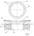
- FIG 2 shows an identical to Figure 1 representation of a second embodiment of the invention Membrane filter plate.
- the embodiments are largely identical, so that identical reference numerals are used for the same or similar elements.
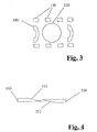
- Figure 3 shows schematically an arrangement of fastening devices around an inlet region in a third embodiment of the membrane filter plate according to the invention. shown are only the locking projections 130 of the support plate 100, which are around the Inlet area 110 are arranged. The locking protrusions 230 of the membrane 200 are arranged analogously.
- two linear arrays of locking protrusions 130 provided on two sides of the inlet area, while on the open sides additional circular segment-shaped locking projections 140 are provided.
- the membrane is made by their attachment position linearly displaced into the locking position, in Figure 3 from the left to the right, wherein the locking projections of the membrane, the locking projections Undercut 130, 140 of the support plate 100.
- Figure 4 shows schematically a locking projection 150 of the support plate 100 and a Lock projection 250 of the membrane, which are provided with stop surfaces 152, 252. These contact surfaces 152, .252 facilitate insertion of the membrane into the carrier plate, wherein upon rotation or displacement of the membrane in the locking position on the Support plate 100 and the membrane 200, a relative force is applied, which is the support plate 100 and the membrane 200 forces each other so that a secure and tight attachment is guaranteed.
- Figures 3 and 4 only are schematic representation, which in particular no orders of magnitude are taken can. The geometric configurations and shapes or contours are only shown schematically.
- FIGS. 5a, 5b, 5c show sealing elements which, in particular in the case of the embodiments shown in FIGS and 2 illustrated embodiments, but also in other embodiments of the invention Membrane filter plate can be used.
- FIG. 5a shows a carrier plate 100 with a guide groove 120 in the bottom of which Sealing groove 310 is formed.
- an O-ring seal 315 is made Rubber used in its relaxed state slightly above the bottom of the guide groove 120 of the support plate 100 protrudes, so that by pressing the guide projection 220 of the membrane 200 is made a sealing connection.
- FIG. 5b shows an embodiment of the membrane filter plate according to the invention, in which the guide projection 220 of the membrane 200, a sealing groove 320 is incorporated, in the, similar to the embodiment shown in Figure 5a, an O-ring seal 325 used is.
- FIG. 5c shows a flat seal 335 which is in a gap between the bottom the guide groove 120 of the support plate 100 and the guide projection 220 of the membrane 200 is arranged.
- the flat seal 335 is a rubber seal in this embodiment, which is formed integrally with the guide groove 120 of the support plate 100 by has been cast on the guide groove 120.
Landscapes
- Chemical & Material Sciences (AREA)
- Chemical Kinetics & Catalysis (AREA)
- Separation Using Semi-Permeable Membranes (AREA)
Description
- Figur 1
- einen Ausschnitt aus einer ersten Ausführungsform einer erfindungsgemäßen Membranfilterplatte in zwei Querschnittsdarstellungen;
- Figur 2
- einen Ausschnitt aus einer zweiten Ausführungsform einer erfindungsgemäßen Membranfilterplatte in zwei Querschnittsdarstellungen;
- Figur 3
- schematisch eine Draufsicht auf eine Anordnung von Befestigungselementen auf einer erfindungsgemäßen Trägerplatte;
- Figur 4
- schematisch einen Querschnitt durch zwei miteinander wechselwirkende Befestigungselemente;
- Figur 5a, 5b, 5c
- schematisch Ausschnitte weiterer Ausführungsformen der erfindungsgemäßen Membranfilterplatte mit unterschiedlichen Dichtungs-Elementen.
Claims (22)
- Mernbranfilterplatte für eine Filterpresse mitdadurch gekennzeichnet, daßeiner Trägerplatte (100) undmindestens einer Membran (200), die lösbar an der Trägerplatte (100) befestigbar ist,wobei die Trägerplatte (100) und die Membran (200) einen Einlauf- und/oder Auslaufbereich aufweisen, unddie Membranfilterplatte im wesentlichen um den Einlauf- und/oder Auslaufbereich der Trägerplatte (100) und/oder der Membran (200) herum Befestigungs-Elemente aufweist,
die Trägerplatte (100) Befestigungs-Elemente (130) und die Membran (200) Befestigungs-Elemente (230) aufweisen, die jeweils fest mit der Trägerplatte (100) bzw. der Membran (200) verbunden und so angeordnet und ausgebildet sind, daß die Befestigungs-Elemente (130) der Trägerplatte (100) mit den Befestigungs-Elementen (230) der Membran (200) nicht wechselwirken, wenn sich die Membran in einer Ansetzposition befindet, und die Befestigungs-Elemente (130) der Trägerplatte (100) mit den Befestigungs-Elementen (230) der Membran (200) so wechselwirken, daß die Membran (200) im Einlauf- und/oder Auslaufbe-reich mittels dieser wechselwirkende Befestigungselemente (130, 230) fest mit der Trägerplatte (200) verbunden ist, wenn sich die Membran (200) in einer Verriegelungsposition befindet. - Membranfilterplatte nach Anspruch 1, dadurch gekennzeichnet, daß es sich bei den Befestigungs-Elementen um jeweils mit Abstand voneinander angeordnete Verriegelungs-Vorsprünge (130, 230) handelt, wobei die Verriegelungs-Vorsprünge (130, 230) an der Trägerplatte (100) und der Membran (200) jeweils so angeordnet sind, daß die Verriegelungs-Vorsprünge (230) der Membran (200) beim Ansetzen der Membran (200) auf die Trägerplatte (100) an den Verriegelungs-Vorsprüngen (130) der Trägerplatte (100) vorbeilaufen, wenn sich die Membran in der Ansetzposition befindet, und daß die Verriegelungs-Vorsprünge (230) der Membran (200) die Verriegelungs-Vorsprünge (130) der Trägerplatte (100) zumindest teilweise hinterschneiden, wenn sich die Membran (200) in der Verriegelungsposition befindet.
- Membranfilterplatte nach Anspruch 1 oder 2, dadurch gekennzeichnet, daß die Membran (200) mittels einer Drehbewegung um einen festgelegten Winkel zwischen der Ansetzposition und der Verriegelungsposition hin- und herschaltbar ist.
- Membranfilterplatte nach Anspruch 3, dadurch gekennzeichnet, daß die Befestigungselemente (130, 230) der Trägerplatte (100) und der Membran (200) jeweils im wesentlichen auf wenigstens einer Kreisbahn angeordnet sind.
- Membranfilterplatte nach Anspruch 1 oder 2, dadurch gekennzeichnet, daß die Membran (200) mittels einer geradlinigen Bewegung um wenigstens einen festgelegten Abstand zwischen der Ansetzposition und der Verriegelungspositon hin- und herschaltbar ist.
- Membranfilterplatte nach Anspruch 5, dadurch gekennzeichnet, daß die Befestigungs-Elemente (130, 230) der Trägerplatte (100) und der Membran (200) jeweils zumindest teilweise in mindestens zwei linearen Anordnungen positioniert sind.
- Membranfilterplatte nach einem der Ansprüche 2 bis 4, dadurch gekennzeichnet, daß sowohl die an der Membran (200) als auch die an der Trägerplatte (100) angeordneten Verriegelungs-Vorsprünge (130, 230) in jeweils zwei konzentrischen Kreisanordnungen positioniert sind.
- Membranfilterplatte nach Anspruch 7, dadurch gekennzeichnet, daß sich die Verriegelungs-Vorsprünge (130, 230) auf den konzentrischen Kreisanordnungen jeweils gegenüberstehen.
- Membranfilterplatte nach Anspruch 7, dadurch gekennzeichnet, daß ein Verriegelungsvorsprung (130, 230) auf einer der Kreisanordnungen jeweils einer Lücke zwischen zwei Verriegelungs-Vorsprüngen (130, 230) auf der anderen Kreisanordnung gegenübersteht.
- Membranfilterplatte nach einem der Ansprüche 2 bis 9, dadurch gekennzeichnet, daß die Membran (200) einen Führungs-Vorsprung (220) aufweist, der sich im wesentlichen senkrecht zur Ebene der Membran (200) in Richtung auf die Trägerplatte (100) erstreckt, wobei der Führungs-Vorsprung (220) in eine Führungs-Nut (120) der Trägerplatte einsetzbar ist.
- Membranfilterplatte nach einem der Ansprüche 2 bis 9, dadurch gekennzeichnet, daß die-Trägerplatte (100) einen Führungs-Vorsprung aufweist, der sich im wesentlichen senkrecht zur Ebene der Trägerplatte (100) in Richtung auf die Trägerplatte (100) erstreckt, wobei der Führungs-Vorsprung in eine Führungs-Nut der Membran einsetzbar ist.
- Membranfilterplatte nach einem der Ansprüche 10 oder 11, dadurch gekennzeichnet, daß sich von der Führungs-Nut (120) und dem Führungs-Vorsprung (220) Verriegelungs-Vorsprünge (130, 230) ein- oder beidseitig erstrecken.
- Membranfilterplatte nach einem der Ansprüche 1 bis 12, dadurch gekennzeichnet, daß die Membran (200) und/oder die Trägerplatte (100) im Bereich der Befestigungselemente (130, 230) mit mindestens einer Dichtung (315, 325, 335) versehen ist.
- Membranfilterplatte nach Anspruch 13, dadurch gekennzeichnet, daß die Dichtung (315) in einer Dichtungs-Nut (310) in der Führungs-Nut (120) der Trägerplatte (100) oder der Membran (200) angeordnet ist.
- Membranfilterplatte nach Anspruch 13, dadurch gekennzeichnet, daß die Dichtung (325) in einer Dichtungs-Nut (320) in dem Führungs-Vorsprung (220) der Membran (200) oder der Trägerplatte (100) angeordnet ist.
- Membranfilterplatte nach Anspruch 13, dadurch gekennzeichnet, daß eine Flach-Dichtung (335) in einem Spalt zwischen Elementen der Membran (200) und der Trägerplatte (100) angeordnet ist.
- Membranfilterplatte nach einem der Ansprüch 13 bis 16, dadurch gekennzeichnet, daß die Dichtung einstückig mit der Trägerplatte (100) oder der Membran (200) ausgebildet ist
- Membranfilterplatte nach einem der vorangehenden Ansprüche, dadurch gekennzeichnet, daß die Membran (200) und die zugehörigen Befestigungs-Elemente (230) aus demselben Material hergestellte sind.
- Membranfilterplatte nach einem der vorangehenden Ansprüche, dadurch gekennzeichnet, daß die Trägerplatte (100) und die zugehörigen Befestigungs-Elemente (130) aus dem selben Material hergestellt sind.
- Membranfilterplatte nach einem der vorangehenden Ansprüche, dadurch gekennzeichnet, daß die Membran (200) und/oder die Trägerplatte (100) und/oder die Befestigungs-Elemente (130, 230) aus einem Kunststoff, insbesondere aus Polypropylen (PP), hergestellt sind.
- Trägerplatte für eine Membranfilterplatte für eine Filterpresse, an die mindestens eine Membran lösbar befestigbar ist, wobei die Trägerplatte einen Einlauf- und/oder Auslaufbereich aufweist und im wesentlichen um den Einlauf- und/oder Auslaufbereich Befestigungselemente vorgesehen sind,
dadurch gekennzeichnet, daß
die Trägerplatte (100) Befestigungs-Elemente (130) aufweist, die fest mit der Trägerplatte verbunden sind und so angeordnet und ausbildet sind, daß die Befestigungselemente (130) der Trägerplatte (100) nicht mit Befestigungselementen (230) einer Membran (200) wechselwirken, wenn sich die Membran (200) in einer Ansetzposition befindet, und die Befestigungs-Elemente (130) der Trägerplatte (100) mit den Befestigungs-Elementen (230) der Membran (200) so wechselwirken, daß die Membran (200) im Einlauf- und/oder Auslaufbereich mittels dieser wechselwirkende Befestigungselemente (130, 230) fest mit der Trägerplatte (200) verbunden ist, wenn sich die Membran (200) in einer Verriegelungsposition befindet. - Membran für eine Membranfilterplatte für eine Filterpresse, die lösbar an einer Trägerplatte befestigbar ist, wobei die Membran einen Einlauf- und/oder Auslaufbereich aufweist und im wesentlichen um den Einlauf- und/oder Auslaufbereich Befestigungselemente vorgesehen sind,
dadurch gekennzeichnet, daß
die Membran (200) Befestigungs-Elemente (230) aufweist, die fest mit der Membran verbunden sind und so angeordnet und ausbildet sind, daß die Befestigungselemente (130) der Membran (200) nicht mit Befestigungselementen (130) einer Trägerplatte (100) wechselwirken, wenn sich die Membran (200) in einer Ansetzposition befindet, und die Befestigungs-Elemente (230) der Membran (200) mit den Befestigungs-Elementen (130) der Trägerplatte (100) so wechselwirken, daß die Membran (200) im Einlauf- und/oder Auslaufbereich mittels dieser wechselwirkende Befestigungselemente (130, 230) fest mit der Trägerplatte (200) verbunden ist, wenn sich die Membran (200) in einer Verriegelungsposition befindet.
Applications Claiming Priority (2)
| Application Number | Priority Date | Filing Date | Title |
|---|---|---|---|
| DE10024722A DE10024722C2 (de) | 2000-05-19 | 2000-05-19 | Membranfilterplatte für eine Filterpresse sowie Trägerplatte und Membran für eine solche Membranfilterplatte |
| DE10024722 | 2000-05-19 |
Publications (3)
| Publication Number | Publication Date |
|---|---|
| EP1159997A2 EP1159997A2 (de) | 2001-12-05 |
| EP1159997A3 EP1159997A3 (de) | 2002-02-20 |
| EP1159997B1 true EP1159997B1 (de) | 2003-12-03 |
Family
ID=7642745
Family Applications (1)
| Application Number | Title | Priority Date | Filing Date |
|---|---|---|---|
| EP01111355A Expired - Lifetime EP1159997B1 (de) | 2000-05-19 | 2001-05-09 | Membranfilterplatte für eine Filterpresse sowie Trägerplatte und Membran für eine solche Membranfilterplatte |
Country Status (3)
| Country | Link |
|---|---|
| EP (1) | EP1159997B1 (de) |
| DE (2) | DE10024722C2 (de) |
| MY (1) | MY119977A (de) |
Families Citing this family (1)
| Publication number | Priority date | Publication date | Assignee | Title |
|---|---|---|---|---|
| ES3034709T3 (en) * | 2020-04-17 | 2025-08-21 | Metso Finland Oy | A filter diaphragm for a horizontal plate and frame -type filter, such as a tower press |
Family Cites Families (8)
| Publication number | Priority date | Publication date | Assignee | Title |
|---|---|---|---|---|
| DE2933034A1 (de) * | 1979-08-16 | 1981-03-26 | Rittershaus & Blecher Gmbh, 42369 Wuppertal | Filterpresse |
| DE8102504U1 (de) * | 1981-01-31 | 1981-07-09 | Sartorius GmbH, 3400 Göttingen | Filtrationsgeraet fuer flachfilterzuschnitte |
| DE3220487C2 (de) * | 1982-05-29 | 1985-01-31 | Lenser Kunststoff-Presswerk Gmbh + Co Kg, 7913 Senden | Filterplatte |
| DE3431401A1 (de) * | 1984-08-27 | 1986-03-06 | Hansen-BTR-GmbH, 3000 Hannover | Membranfilterplatte |
| DE8812139U1 (de) * | 1988-09-26 | 1989-02-02 | Neu, Werner, Dr., 8038 Gröbenzell | Membranfilterplatte |
| US4911839A (en) * | 1989-02-06 | 1990-03-27 | Baker Hughes Incorporated | Membrane filter plate |
| DE4119166C2 (de) * | 1991-06-11 | 1998-10-01 | Lenser Kunststoff Preswerk Gmb | Filterelement für eine Filterpresse |
| DE4415274C2 (de) * | 1994-04-30 | 1998-04-30 | Jv Kunststoffwerk | Filterplatte für eine Plattenfilterpresse |
-
2000
- 2000-05-19 DE DE10024722A patent/DE10024722C2/de not_active Expired - Lifetime
-
2001
- 2001-05-09 DE DE50101064T patent/DE50101064D1/de not_active Expired - Lifetime
- 2001-05-09 EP EP01111355A patent/EP1159997B1/de not_active Expired - Lifetime
- 2001-05-21 MY MYPI20012387A patent/MY119977A/en unknown
Also Published As
| Publication number | Publication date |
|---|---|
| EP1159997A2 (de) | 2001-12-05 |
| MY119977A (en) | 2005-08-30 |
| EP1159997A3 (de) | 2002-02-20 |
| DE50101064D1 (de) | 2004-01-15 |
| DE10024722A1 (de) | 2001-11-22 |
| DE10024722C2 (de) | 2003-02-20 |
Similar Documents
| Publication | Publication Date | Title |
|---|---|---|
| EP1649920B1 (de) | Luftfilter | |
| EP0155458B1 (de) | Membranfilterplatte | |
| EP1503839B1 (de) | Plattenpaket für eine filterpresse | |
| EP3523004B1 (de) | Anordnung einer filterplatte und eines anbauteils | |
| EP1231995A1 (de) | Filterplatte einer filterpresse | |
| DE4119166C2 (de) | Filterelement für eine Filterpresse | |
| DE3240953C2 (de) | ||
| EP0556186B1 (de) | Membranplatte für plattenfilterpressen | |
| EP1294462B1 (de) | Filtermodul | |
| DE4415274C2 (de) | Filterplatte für eine Plattenfilterpresse | |
| DE69601075T2 (de) | Filtervorrichtung | |
| EP0149820A2 (de) | Membranfilterplatte für eine Filterpresse | |
| DE3233126C2 (de) | Membranplatte für eine Filterpresse | |
| EP0247288A2 (de) | Filterpresse | |
| EP0505518B1 (de) | Filterplatte für eine plattenfilterpresse | |
| EP2427252B1 (de) | Membranträger für eine filterpresse | |
| EP0687492A2 (de) | Membranfilterplatte für eine Filterpresse | |
| EP0208076B1 (de) | Membranfilterplatte mit Trägerplatte und Dichtrand | |
| EP0827766A1 (de) | Pressmembran für eine Membranplatte einer Plattenfilterpresse | |
| EP0233980B1 (de) | Membranfilterplatte für eine Filterpresse oder dergleichen mit Stütznocken | |
| DE1767884B2 (de) | Verschluß fur einen Druckbehälter | |
| DE10024722C2 (de) | Membranfilterplatte für eine Filterpresse sowie Trägerplatte und Membran für eine solche Membranfilterplatte | |
| EP1163943B1 (de) | Membranfilterplatte für eine Filterpresse sowie Trägerplatte und Membran für eine solche Membranfilterplatte | |
| EP1231996B1 (de) | Pressmembran aus einem gummielastischen material | |
| WO2005016487A1 (de) | Heizelement für eine filterpresse |
Legal Events
| Date | Code | Title | Description |
|---|---|---|---|
| PUAI | Public reference made under article 153(3) epc to a published international application that has entered the european phase |
Free format text: ORIGINAL CODE: 0009012 |
|
| AK | Designated contracting states |
Kind code of ref document: A2 Designated state(s): DE FR GB IT Kind code of ref document: A2 Designated state(s): AT BE CH CY DE DK ES FI FR GB GR IE IT LI LU MC NL PT SE TR |
|
| AX | Request for extension of the european patent |
Free format text: AL;LT;LV;MK;RO;SI |
|
| PUAL | Search report despatched |
Free format text: ORIGINAL CODE: 0009013 |
|
| AK | Designated contracting states |
Kind code of ref document: A3 Designated state(s): AT BE CH CY DE DK ES FI FR GB GR IE IT LI LU MC NL PT SE TR |
|
| AX | Request for extension of the european patent |
Free format text: AL;LT;LV;MK;RO;SI |
|
| 17P | Request for examination filed |
Effective date: 20020322 |
|
| AKX | Designation fees paid |
Free format text: DE FR GB IT |
|
| GRAH | Despatch of communication of intention to grant a patent |
Free format text: ORIGINAL CODE: EPIDOS IGRA |
|
| GRAS | Grant fee paid |
Free format text: ORIGINAL CODE: EPIDOSNIGR3 |
|
| GRAA | (expected) grant |
Free format text: ORIGINAL CODE: 0009210 |
|
| AK | Designated contracting states |
Kind code of ref document: B1 Designated state(s): DE FR GB IT |
|
| REG | Reference to a national code |
Ref country code: GB Ref legal event code: FG4D Free format text: NOT ENGLISH |
|
| GBT | Gb: translation of ep patent filed (gb section 77(6)(a)/1977) |
Effective date: 20031203 |
|
| REG | Reference to a national code |
Ref country code: IE Ref legal event code: FG4D Free format text: GERMAN |
|
| REF | Corresponds to: |
Ref document number: 50101064 Country of ref document: DE Date of ref document: 20040115 Kind code of ref document: P |
|
| ET | Fr: translation filed | ||
| REG | Reference to a national code |
Ref country code: IE Ref legal event code: FD4D |
|
| PLBE | No opposition filed within time limit |
Free format text: ORIGINAL CODE: 0009261 |
|
| STAA | Information on the status of an ep patent application or granted ep patent |
Free format text: STATUS: NO OPPOSITION FILED WITHIN TIME LIMIT |
|
| 26N | No opposition filed |
Effective date: 20040906 |
|
| REG | Reference to a national code |
Ref country code: DE Ref legal event code: R082 Ref document number: 50101064 Country of ref document: DE Representative=s name: BOEHMERT & BOEHMERT, DE |
|
| REG | Reference to a national code |
Ref country code: DE Ref legal event code: R081 Ref document number: 50101064 Country of ref document: DE Owner name: KLINKAU GMBH + CO. KG, DE Free format text: FORMER OWNER: KLINKAU GMBH + CO., 87616 MARKTOBERDORF, DE Effective date: 20140722 Ref country code: DE Ref legal event code: R082 Ref document number: 50101064 Country of ref document: DE Representative=s name: BOEHMERT & BOEHMERT ANWALTSPARTNERSCHAFT MBB -, DE Effective date: 20140722 |
|
| REG | Reference to a national code |
Ref country code: FR Ref legal event code: PLFP Year of fee payment: 16 |
|
| REG | Reference to a national code |
Ref country code: FR Ref legal event code: PLFP Year of fee payment: 17 |
|
| REG | Reference to a national code |
Ref country code: FR Ref legal event code: PLFP Year of fee payment: 18 |
|
| PGFP | Annual fee paid to national office [announced via postgrant information from national office to epo] |
Ref country code: FR Payment date: 20200414 Year of fee payment: 20 Ref country code: DE Payment date: 20200529 Year of fee payment: 20 |
|
| PGFP | Annual fee paid to national office [announced via postgrant information from national office to epo] |
Ref country code: IT Payment date: 20200414 Year of fee payment: 20 Ref country code: GB Payment date: 20200429 Year of fee payment: 20 |
|
| REG | Reference to a national code |
Ref country code: DE Ref legal event code: R071 Ref document number: 50101064 Country of ref document: DE |
|
| REG | Reference to a national code |
Ref country code: GB Ref legal event code: PE20 Expiry date: 20210508 |
|
| PG25 | Lapsed in a contracting state [announced via postgrant information from national office to epo] |
Ref country code: GB Free format text: LAPSE BECAUSE OF EXPIRATION OF PROTECTION Effective date: 20210508 |