EP1158725B1 - Verfahren und Vorrichtung zur Mehrfach- Routerredundanzprotokolls Unterstützung - Google Patents
Verfahren und Vorrichtung zur Mehrfach- Routerredundanzprotokolls Unterstützung Download PDFInfo
- Publication number
- EP1158725B1 EP1158725B1 EP01112006A EP01112006A EP1158725B1 EP 1158725 B1 EP1158725 B1 EP 1158725B1 EP 01112006 A EP01112006 A EP 01112006A EP 01112006 A EP01112006 A EP 01112006A EP 1158725 B1 EP1158725 B1 EP 1158725B1
- Authority
- EP
- European Patent Office
- Prior art keywords
- router
- packet
- redundant
- protocol type
- address
- Prior art date
- Legal status (The legal status is an assumption and is not a legal conclusion. Google has not performed a legal analysis and makes no representation as to the accuracy of the status listed.)
- Expired - Lifetime
Links
Images


Classifications
-
- H—ELECTRICITY
- H04—ELECTRIC COMMUNICATION TECHNIQUE
- H04L—TRANSMISSION OF DIGITAL INFORMATION, e.g. TELEGRAPHIC COMMUNICATION
- H04L45/00—Routing or path finding of packets in data switching networks
- H04L45/22—Alternate routing
-
- H—ELECTRICITY
- H04—ELECTRIC COMMUNICATION TECHNIQUE
- H04L—TRANSMISSION OF DIGITAL INFORMATION, e.g. TELEGRAPHIC COMMUNICATION
- H04L45/00—Routing or path finding of packets in data switching networks
-
- H—ELECTRICITY
- H04—ELECTRIC COMMUNICATION TECHNIQUE
- H04L—TRANSMISSION OF DIGITAL INFORMATION, e.g. TELEGRAPHIC COMMUNICATION
- H04L45/00—Routing or path finding of packets in data switching networks
- H04L45/28—Routing or path finding of packets in data switching networks using route fault recovery
-
- H—ELECTRICITY
- H04—ELECTRIC COMMUNICATION TECHNIQUE
- H04L—TRANSMISSION OF DIGITAL INFORMATION, e.g. TELEGRAPHIC COMMUNICATION
- H04L45/00—Routing or path finding of packets in data switching networks
- H04L45/44—Distributed routing
-
- H—ELECTRICITY
- H04—ELECTRIC COMMUNICATION TECHNIQUE
- H04L—TRANSMISSION OF DIGITAL INFORMATION, e.g. TELEGRAPHIC COMMUNICATION
- H04L45/00—Routing or path finding of packets in data switching networks
- H04L45/50—Routing or path finding of packets in data switching networks using label swapping, e.g. multi-protocol label switch [MPLS]
-
- H—ELECTRICITY
- H04—ELECTRIC COMMUNICATION TECHNIQUE
- H04L—TRANSMISSION OF DIGITAL INFORMATION, e.g. TELEGRAPHIC COMMUNICATION
- H04L45/00—Routing or path finding of packets in data switching networks
- H04L45/52—Multiprotocol routers
-
- H—ELECTRICITY
- H04—ELECTRIC COMMUNICATION TECHNIQUE
- H04L—TRANSMISSION OF DIGITAL INFORMATION, e.g. TELEGRAPHIC COMMUNICATION
- H04L45/00—Routing or path finding of packets in data switching networks
- H04L45/54—Organization of routing tables
-
- H—ELECTRICITY
- H04—ELECTRIC COMMUNICATION TECHNIQUE
- H04L—TRANSMISSION OF DIGITAL INFORMATION, e.g. TELEGRAPHIC COMMUNICATION
- H04L45/00—Routing or path finding of packets in data switching networks
- H04L45/58—Association of routers
- H04L45/586—Association of routers of virtual routers
-
- H—ELECTRICITY
- H04—ELECTRIC COMMUNICATION TECHNIQUE
- H04L—TRANSMISSION OF DIGITAL INFORMATION, e.g. TELEGRAPHIC COMMUNICATION
- H04L47/00—Traffic control in data switching networks
- H04L47/10—Flow control; Congestion control
- H04L47/20—Traffic policing
-
- H—ELECTRICITY
- H04—ELECTRIC COMMUNICATION TECHNIQUE
- H04L—TRANSMISSION OF DIGITAL INFORMATION, e.g. TELEGRAPHIC COMMUNICATION
- H04L47/00—Traffic control in data switching networks
- H04L47/10—Flow control; Congestion control
- H04L47/24—Traffic characterised by specific attributes, e.g. priority or QoS
- H04L47/2408—Traffic characterised by specific attributes, e.g. priority or QoS for supporting different services, e.g. a differentiated services [DiffServ] type of service
-
- H—ELECTRICITY
- H04—ELECTRIC COMMUNICATION TECHNIQUE
- H04L—TRANSMISSION OF DIGITAL INFORMATION, e.g. TELEGRAPHIC COMMUNICATION
- H04L47/00—Traffic control in data switching networks
- H04L47/10—Flow control; Congestion control
- H04L47/24—Traffic characterised by specific attributes, e.g. priority or QoS
- H04L47/2441—Traffic characterised by specific attributes, e.g. priority or QoS relying on flow classification, e.g. using integrated services [IntServ]
-
- H—ELECTRICITY
- H04—ELECTRIC COMMUNICATION TECHNIQUE
- H04L—TRANSMISSION OF DIGITAL INFORMATION, e.g. TELEGRAPHIC COMMUNICATION
- H04L47/00—Traffic control in data switching networks
- H04L47/10—Flow control; Congestion control
- H04L47/24—Traffic characterised by specific attributes, e.g. priority or QoS
- H04L47/2458—Modification of priorities while in transit
-
- H—ELECTRICITY
- H04—ELECTRIC COMMUNICATION TECHNIQUE
- H04L—TRANSMISSION OF DIGITAL INFORMATION, e.g. TELEGRAPHIC COMMUNICATION
- H04L47/00—Traffic control in data switching networks
- H04L47/10—Flow control; Congestion control
- H04L47/31—Flow control; Congestion control by tagging of packets, e.g. using discard eligibility [DE] bits
-
- H—ELECTRICITY
- H04—ELECTRIC COMMUNICATION TECHNIQUE
- H04L—TRANSMISSION OF DIGITAL INFORMATION, e.g. TELEGRAPHIC COMMUNICATION
- H04L47/00—Traffic control in data switching networks
- H04L47/10—Flow control; Congestion control
- H04L47/32—Flow control; Congestion control by discarding or delaying data units, e.g. packets or frames
-
- H—ELECTRICITY
- H04—ELECTRIC COMMUNICATION TECHNIQUE
- H04L—TRANSMISSION OF DIGITAL INFORMATION, e.g. TELEGRAPHIC COMMUNICATION
- H04L49/00—Packet switching elements
- H04L49/35—Switches specially adapted for specific applications
- H04L49/351—Switches specially adapted for specific applications for local area network [LAN], e.g. Ethernet switches
-
- H—ELECTRICITY
- H04—ELECTRIC COMMUNICATION TECHNIQUE
- H04L—TRANSMISSION OF DIGITAL INFORMATION, e.g. TELEGRAPHIC COMMUNICATION
- H04L69/00—Network arrangements, protocols or services independent of the application payload and not provided for in the other groups of this subclass
- H04L69/22—Parsing or analysis of headers
-
- H—ELECTRICITY
- H04—ELECTRIC COMMUNICATION TECHNIQUE
- H04L—TRANSMISSION OF DIGITAL INFORMATION, e.g. TELEGRAPHIC COMMUNICATION
- H04L41/00—Arrangements for maintenance, administration or management of data switching networks, e.g. of packet switching networks
- H04L41/50—Network service management, e.g. ensuring proper service fulfilment according to agreements
- H04L41/5003—Managing SLA; Interaction between SLA and QoS
- H04L41/5006—Creating or negotiating SLA contracts, guarantees or penalties
-
- H—ELECTRICITY
- H04—ELECTRIC COMMUNICATION TECHNIQUE
- H04L—TRANSMISSION OF DIGITAL INFORMATION, e.g. TELEGRAPHIC COMMUNICATION
- H04L49/00—Packet switching elements
- H04L49/10—Packet switching elements characterised by the switching fabric construction
- H04L49/103—Packet switching elements characterised by the switching fabric construction using a shared central buffer; using a shared memory
-
- H—ELECTRICITY
- H04—ELECTRIC COMMUNICATION TECHNIQUE
- H04L—TRANSMISSION OF DIGITAL INFORMATION, e.g. TELEGRAPHIC COMMUNICATION
- H04L49/00—Packet switching elements
- H04L49/20—Support for services
- H04L49/205—Quality of Service based
-
- H—ELECTRICITY
- H04—ELECTRIC COMMUNICATION TECHNIQUE
- H04L—TRANSMISSION OF DIGITAL INFORMATION, e.g. TELEGRAPHIC COMMUNICATION
- H04L49/00—Packet switching elements
- H04L49/30—Peripheral units, e.g. input or output ports
- H04L49/3027—Output queuing
-
- H—ELECTRICITY
- H04—ELECTRIC COMMUNICATION TECHNIQUE
- H04L—TRANSMISSION OF DIGITAL INFORMATION, e.g. TELEGRAPHIC COMMUNICATION
- H04L49/00—Packet switching elements
- H04L49/35—Switches specially adapted for specific applications
- H04L49/354—Switches specially adapted for specific applications for supporting virtual local area networks [VLAN]
-
- H—ELECTRICITY
- H04—ELECTRIC COMMUNICATION TECHNIQUE
- H04L—TRANSMISSION OF DIGITAL INFORMATION, e.g. TELEGRAPHIC COMMUNICATION
- H04L49/00—Packet switching elements
- H04L49/60—Software-defined switches
- H04L49/602—Multilayer or multiprotocol switching, e.g. IP switching
Definitions
- the present invention is related to redundant routing, and particularly to a method and apparatus for providing multi-protocol redundant router protocol support.
- Redundant routing protocols have been developed to provide hosts configured with static routes a measure of protection against router failure.
- a host is configured to send to a virtual router MAC address that is supported by two or more physical routers sharing a LAN with the host.
- one of the physical routers a virtual master
- the other backup routers standby to assume forwarding responsibilities in the event the virtual master fails.
- the transition by which respective ones of the backup routers become the virtual master is transparent to the host.
- redundant routing protocols can be used advantageously in LANs having two or more hosts to achieve load sharing.
- at least two hosts are assigned different ones of virtual router MAC addresses such that different ones of the physical routers become the initial virtual master for the different ones of the hosts.
- LAN local area network
- a local area network includes a plurality of hosts, a plurality of physical routers and a LAN medium interconnecting the hosts and the physical routers.
- a first one of the hosts applies a packet of a first redundant router protocol type to the LAN medium and a second one of the hosts applies a packet of a second redundant router protocol type to the LAN medium.
- the physical routers determine responsibility for forwarding a packet received on the LAN medium in function of a redundant router protocol type of the packet.
- a method of routing a plurality of packets using a plurality of redundant routing protocols is provided.
- a router receives a packet having a packet address.
- a prefix of the packet address is compared with a first predefined value to determine whether the packet is of a first redundant routing protocol type.
- the prefix of the packet address is compared with a second predefined value to determine whether the packet is of a second redundant routing protocol type.
- a router for receiving and forwarding one or more packets.
- the router includes a first comparator for comparing a packet address prefix and a first predefined value to determine whether the packet is of a first redundant router protocol type.
- the router also includes a second comparator for comparing the packet address prefix and a second predefined value to determine whether the packet is of a second redundant router protocol type.
- FIG. 1 is a system diagram of an apparatus for supporting both HSRP and VRRP protocols according to an embodiment of the present invention.
- a local area network includes a plurality of hosts 100, 102, 104, 106 and a plurality of routers 110, 116, which are physical (as opposed to virtual) routers.
- the routers 110 and 116 are coupled to a computer network 120.
- the routers 110, 116 may be viewed as being coupled to the LAN to provide gateway to the computer network 120.
- the routers 110, 116 may be coupled to one or more LANs other than the LAN of FIG. 1 .
- the computer network 120 may include the Internet or other global or local computer networks.
- the routers 110 and 116 may also be coupled to one or more other LANs (not shown).
- the LANs in this and other embodiments may have one or more different configurations including, but not limited to, Ethernet (IEEE 802.3), token ring (IEEE 802.5) and FDDI (ANSI X3T9.5).
- the hosts 100 and 104 preferably are associated with a group of redundant routers HSRP Group 1 and HSRP Group 2, respectively.
- the hosts 102 and 106 are associated with a group of redundant routers VRRP Group1 and VRRP Group 2, respectively.
- the hosts and routers of FIG. 1 are shown for illustrative purposes only. In practice, the LAN may include one or more additional hosts and routers belonging to HSRP Groups 1 and/or 2, VRRP Groups 1 and/or 2, and/or other HSRP and/or VRRP groups.
- the redundant routers in each group share a common virtual router address, which is assigned to one or more hosts associated with the group of redundant routers.
- the virtual router addresses may include a Media Access Control (MAC) address, a network address (e.g., IP address) or both.
- MAC Media Access Control
- IP address e.g., IP address
- the host assigned to a virtual router address transmits one or more data units (e.g., Ethernet frames, IP packets or ATM cells) to be routed, the data units are directed to one of the redundant routers in the group that is acting as the virtual master for that particular group.
- data units e.g., Ethernet frames, IP packets or ATM cells
- data units from the host 100 preferably are routed by an HSRP Group 1 virtual router 108
- data units from the host 102 preferably are routed by a VRRP Group 1 virtual router 118
- data units from the host 104 preferably are routed by an HSRP Group 2 virtual router 114
- data units from the host 106 preferably are routed by a VRRP Group 2 virtual router 112.
- the HSRP and VRRP virtual routers 108, 112, 114 and 118 are not physical routers, their virtual router addresses preferably are mapped to the routers 110 and 116.
- the router 110 preferably is configured as an HSRP Group 1 virtual master and a VRRP Group 2 virtual master.
- the router 116 is configured as a VRRP Group 1 virtual master and an HSRP Group 2 virtual master.
- Virtual masters may also be referred to as active routers, virtual router masters or Masters.
- the routers 110 and 116 are illustrated to be supporting four groups of virtual routers (i.e., HSRP Group 1 virtual router, VRRP Group 2 virtual router, HSRP Group 2 virtual router, and VRRP Group 1 virtual router). Therefore, for example, when the router 110 operates as the HSRP Group 1 virtual master and the VRRP Group 2 virtual master, the router 116 may operate as an HSRP Group 1 standby router and a VRRP Group 2 standby router. For another example, when the router 116 operates as the HSRP Group 2 virtual master and the VRRP Group 1 virtual master, the router 110 may operate as an HSRP Group 2 standby router and a VRRP Group 1 standby router. Standby routers may also be referred to as backup routers. In other embodiments, each physical router may be mapped to one HSRP group of redundant routers and one VRRP group of redundant routers.
- each of the routers 110 and 116 may support up to four HSRP virtual router groups and up to four VRRP virtual router groups simultaneously on up to 512 different LANs. In other embodiments, each of the routers 110 and 116 may support more than four HSRP virtual router groups and more than four VRRP virtual router groups simultaneously on 512 or more different LANs.
- the packet switching node 120 may be used as one or both of the routers 110 and 116.
- the packet switching node 120 includes a number of switching interfaces 124, 126, 128 preferably interconnected to respective groups of LANs 130, 132, 134 and preferably interconnected to each other over data paths 138, 140, 142 via a switching backplane 122 and over control paths 144, 146.
- the switching interfaces 124, 126, 128 preferably forward packets to and from their respective groups of LANs 130, 132, 134 in accordance with one or more operative communication protocols, such as, for example, media access control (MAC) bridging and Internet Protocol (IP) routing.
- MAC media access control
- IP Internet Protocol
- the switching interfaces 124, 126 and 128 preferably communicate with other packet switching nodes over a computer network 136, which may include the Internet and/or other global or local computer networks.
- FIG. 3 is a block diagram of a switching interface 150, which may be similar to one or more of the switching interfaces 124, 126 and 128.
- the switching interface 150 includes an access controller 154 coupled between the LANs and a packet switching controller 152.
- the access controller 154 preferably receives inbound packets off LANs, performs flow-independent physical and MAC layer operations on the inbound packets and transmits the inbound packets to the packet switching controller 152 for flow-dependent processing.
- the access controller 154 preferably also receives outbound packets from the packet switching controller 152, preferably performs physical and MAC layer operations on the outbound packets and transmits the outbound packets on the LANs or to a computer network, such as, for example, the computer network 136 of FIG. 2 .
- the packet switching controller 152 preferably receives inbound packets, classifies the packets, generates application data for the inbound packets, modifies the inbound packets in accordance with the application data, and transmits the modified inbound packets on a switching backplane, such as, for example, the switching backplane 122 of FIG. 2 .
- the packet switching controller 152 preferably also receives outbound packets from other packet switching controllers over the backplane, and transmits the outbound packets to the access controller 154 for forwarding on the LANs or to the computer network, such as, for example, the compute network 136 of FIG. 2 .
- the packet switching controller 152 may also subject one or more outbound packets to egress processing prior to forwarding them to the access controller 154.
- the packet switching controller 152 may be implemented in non-programmable logic, programmable logic or any combination of programmable and non-programmable logic.
- FIG. 4 is a block diagram of a programmable packet switching controller 200 according to an embodiment of the present invention.
- the programmable packet switching controller 200 may be similar to the packet switching controller 152 of FIG. 3 .
- the programmable packet switching controller 200 preferably has flow resolution logic for classifying and routing incoming flows of packets.
- Packet switching controllers in other embodiments may include more or less number of components.
- a packet switching controller in another embodiment may include a pattern match module for comparing packet portions against a predetermined pattern to look for a match.
- the packet switching controller in yet another embodiment may include an edit module for editing inbound packets to generate outbound packets.
- packet switching controllers in still other embodiments may include other components, such as, for example, a policing engine, in addition to or instead of the components included in the programmable packet switching controller 200.
- the programmable packet switching controller 200 preferably provides flexibility in handling many different protocols and/or field upgradeability.
- the programmable packet switching controller 200 may also be referred to as a packet switching controller, a switching controller, a programmable packet processor, a network processor, a communications processor or as another designation commonly used by those skilled in the art.
- the programmable packet switching controller 200 includes a packet buffer 202, a packet classification engine 204, and an application engine 206.
- the programmable packet switching controller 200 preferably receives inbound packets 208.
- the packets (or data units) may include, but are not limited to, Ethernet frames, ATM cells, TCP/IP and/or UDP/IP packets, and may also include other Layer 2 (Data Link/MAC Layer), Layer 3 (Network Layer) or Layer 4 (Transport Layer) data units.
- the packet buffer 202 may receive inbound packets from one or more Media Access Control (MAC) Layer interfaces over the Ethernet.
- MAC Media Access Control
- the received packets preferably are stored in the packet buffer 202.
- the packet buffer 202 may include a packet FIFO for receiving and temporarily storing the packets.
- the packet buffer 202 preferably provides the stored packets or portions thereof to the packet classification engine 204 and the application engine 206 for processing.
- the packet buffer 202 may also include an edit module for editing the packets prior to forwarding them out of the switching controller as outbound packets 218.
- the edit module may include an edit program construction engine for creating edit programs real-time and/or an edit engine for modifying the packets.
- the application engine 206 preferably provides application data 216, which may include a disposition decision for the packet, to the packet buffer 202, and the edit program construction engine preferably uses the application data to create the edit programs.
- the outbound packets 218 may be transmitted over a switching fabric interface to communication networks, such as, for example, the Ethernet.
- the packet buffer 202 may also include either or both a header data extractor and a header data cache.
- the header data extractor preferably is used to extract one or more fields from the packets, and to store the extracted fields in the header data cache as extracted header data.
- the extracted header data may include, but are not limited to, some or all of the packet header. In an Ethernet system, for example, the header data cache may also store first N bytes of each frame.
- the extracted header data preferably is provided in an output signal 210 to the packet classification engine 204 for processing.
- the application engine may also request and receive the extracted header data over an interface 214.
- the extracted header data may include, but are not limited to, one or more of Layer 2 MAC addresses, 802.1P/Q tag status, Layer 2 encapsulation type, Layer 3 protocol type, Layer 3 addresses, ToS (type of service) values and Layer 4 port numbers.
- the output signal 210 may include the whole inbound packet, instead of or in addition to the extracted header data.
- the packet classification engine 204 may be used to edit the extracted header data to be placed in a format suitable for use by the application engine, and/or to load data into the header data cache.
- the packet classification engine 204 preferably includes a programmable microcode-driven embedded processing engine.
- the packet classification engine 204 preferably is coupled to an instruction RAM (IRAM) (not shown).
- IRAM instruction RAM
- the packet classification engine preferably reads and executes instructions stored in the IRAM. In one embodiment, many of the instructions executed by the packet classification engine are conditional jumps.
- the classification logic includes a decision tree with leaves at the end points that preferably indicate different types of packet classifications. Further, branches of the decision tree preferably are selected based on comparisons between the conditions of the instructions and the header fields stored in the header data cache. In other embodiments, the classification logic may not be based on a decision tree.
- the application engine 206 preferably has a pipelined architecture wherein multiple programmable sub-engines are pipelined in series. Each programmable sub-engine preferably performs an action on the packet, and preferably forwards the packet to the next programmable sub-engine in a "bucket brigade" fashion.
- the packet classification engine preferably starts the pipelined packet processing by starting the first programmable sub-engine in the application engine using a start signal 212.
- the start signal 212 may include identification of one or more programs to be executed in the application engine 206.
- the start signal 212 may also include packet classification information.
- the programmable sub-engines in the application engine preferably have direct access to the header data and the extracted fields stored in the header data cache over the interface 214.
- the application engine may include other processing stages not performed by the programmable sub-engines, however, the decision-making stages preferably are performed by the programmable sub-engines to increase flexibility. In other embodiments, the application engine may include other processing architectures.
- FIG. 5 is a schematic diagram illustrating a process of determining whether the incoming data unit is of the type HSRP or VRRP, according to an embodiment of the present invention.
- the schematic diagram of FIG. 5 includes a prefix match block 250 and a database table 252.
- the prefix match block 250 may be included in a packet classification engine, such as, for example, the packet classification engine 204 of FIG. 4 .
- the prefix match block 250 may be included in an application engine, such as, for example, the application engine 206 of FIG. 4 .
- the database table 254 preferably includes a bit table, which is indexed by protocol selection (HSRP or VRRP), VLAN number (or VLAN ID/address) and group number (or group ID) to yield a single bit result.
- the database table 254 may be in other table format and other parameters may be used to index the table.
- the result yielded by the database table 254 may include multiple bits in other embodiments.
- the database table 254 may be included in the application engine or it may be implemented in memory external to the application engine.
- FIG. 5 may be described in reference to FIG. 6.
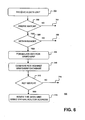
- FIG. 6 is a flow diagram illustrating a process of determining whether the incoming data unit is of the type HSRP or VRRP according to an embodiment of the present invention.
- the process receives a data unit.
- the data unit includes a destination address, which may include a destination Media Access Control (DMAC) address an/or a Virtual Local Area Network (VLAN) ID.
- DMAC Destination Control
- VLAN Virtual Local Area Network
- An exemplary DMAC address and VLAN ID illustrated in FIG. 5 contains 48 bits and 12 bits, respectively.
- the prefix match block 250 preferably is used to determine whether the received data unit is of the type HSRP or VRRP.
- Each of the HSRP and VRRP router MAC addresses includes an IEEE 802 MAC address, and has predefined 40-bit prefix with an 8-bit group suffix.
- the virtual MAC address for an HSRP group may be 00-00-0C-07-AC-XX, where each of 00, 0C, 07 and AC is an 8-bit hexadecimal number and XX is an 8-bit group ID for the HSRP group.
- the virtual MAC address for an VRRP group may be 00-00-5E-00-01-XX, wherein each of 00, 5E and 01 is an 8-bit hexadecimal number and XX is an 8-bit group ID for the VRRP group. If the first 40 bit prefix of the received DMAC matches 40-bit prefix for neither HSRP nor VRRP, the process indicates no prefix match in a decision 304. If there is no prefix match, the data unit may not have been directed to one of the virtual routers.
- the prefix match block 250 preferably also checks the VLAN ID and the VRRP/HSRP group ID of the received data unit to determine whether they are within a predetermined range of values. For example, in the embodiment where a router may support up to 512 different LANs simultaneously, the value of the VLAN ID should be between 0 and 511, inclusive. For another example, in the embodiment where a router may support up to four HSRP groups and/or four VRRP groups simultaneously, the value of the VRRP/HSRP group ID should be between 0 and 3, inclusive. If either the VLAN ID or the VRRP/HSRP group ID is not within their respective range of values, the process indicates out of range in a decision 306. If either the VLAN ID or the VRRP/HSRP group ID is out of range, the data unit may be routed using software, but typically at a slower rate.
- additional number of different LANs and/or additional number of VRRP/HSRP groups may be supported.
- up to 4096 different LANs may be supported using all 12 bits of a 12-bit VLAN ID and up to 256 VRRP/HSRP groups may be supported using all 8 bits of an 8-bit group ID.
- the prefix match block 250 preferably formats a key for matching in the database table 252.
- the key contains 12 bits. In other embodiments, the key may include more or less number of bits than 12.
- the key preferably includes a protocol ID 254, a VLAN address 256 and a group ID 258.
- the protocol ID 254 preferably is a single bit identification of either HSRP or VRRP.
- the VLAN address 256 preferably includes nine least significant bits (LSBs) of the 12-bit VLAN ID for the received data unit.
- the group ID preferably includes two bits to signify either the VRRP or HSRP group ID.
- the router including the prefix match block of the described embodiment is capable of processing HSRP and VRRP packets concurrently with up to 4 groups of each type on up to 512 VLANs.
- the number of bits in the protocol ID 254, the VLAN address 256 and/or the group ID 258 may be different, and may result in different HSRP and/or VRRP packet processing capabilities.
- the number of bits in the protocol ID, the VLAN address and/or the group ID may be programmable to support different number of redundant router protocols (e.g., protocols other than HSRP and VRRP may be defined in the future) and/or virtual router addresses.
- the key preferably is compared against one or more entries in the database table 252.
- the data base table may include VRRP/HSRP database, which may also be referred to as VRRP/HSRP virtual master database. If the key does not match any of the entries in the database table 252, the router containing the database table is not operating (314) as the virtual master for the host that transmitted the data unit. If the key matches an entry in the database table, a match bit is generated to indicate that the router is operating as the virtual master.
- the data unit preferably is routed (or switched) using the virtual router address when the key matches, as indicated in step 316.
- multi-protocol redundant router protocol support in programmable packet switching controllers.
- the multi-protocol redundant router protocol support of the present invention may also be applied to non-programmable, e.g., hard-wired, packet switching controllers.
Landscapes
- Engineering & Computer Science (AREA)
- Computer Networks & Wireless Communication (AREA)
- Signal Processing (AREA)
- Computer Security & Cryptography (AREA)
- Data Exchanges In Wide-Area Networks (AREA)
- Small-Scale Networks (AREA)
- Communication Control (AREA)
Claims (24)
- Ein lokales Netz, LAN, umfassend:Eine Vielzahl von Hosts (100, 102, 104, 106);eine Vielzahl von physikalischen Routern (110, 116): undein LAN-Medium, welches die Hosts und die physikalischen Router miteinander verbindet;wobei ein erster der Hosts fähig ist, ein Paket eines ersten Routerredundanzprotokoll-Typs auf ein LAN-Medium aufzulegen,
dadurch gekennzeichnet, dassein zweiter der Hosts fähig ist, ein Paket eines zweiten Routerredundanzprotokoll-Typs auf ein LAN-Medium aufzulegen, wobei das erste und das zweite Routerredundanzprotokoll nicht interoperabel sind;ein jeder der physikalischen Router (110, 116) fähig ist, Pakete des ersten Routerredundanzprotokoll-Typs und des zweiten Routerredundanzprotokoll-Typs gleichzeitig weiterzuleiten;die physikalischen Router (110, 116) fähig sind, einen Präfix einer Zieladresse eines eingehenden Pakets mit einem ersten vorgegebenen Wert zu vergleichen, um zu ermitteln, ob das eingehende Paket dem ersten Routerredundanzprotokoll-Typ entspricht;die physikalischen Router (110, 116) fähig sind, den Präfix einer Zieladresse eines eingehenden Pakets mit einem zweiten vorgegebenen Wert zu vergleichen, um zu ermitteln, ob das eingehende Paket dem zweiten Routerredundanzprotokoll-Typ entspricht;die physikalischen Router (110, 116) fähig sind, die Zuständigkeit für die Übertragung eines an dem LAN-Medium empfangenen Pakets als eine Funktion des ermittelten Routerredundanzprotokoll-Typs des Pakets zu bestimmen. - Das LAN nach Anspruch 1, wobei der erste Routerredundanzprotokoll-Typ ein virtuelles Routerredundanzprotokoll, VRRP, und der zweite Routerredundanzprotokoll-Typ ein Hot-Standby-Routerprotokoll, HSRP, ist.
- Das LAN nach Anspruch 1, wobei die Vielzahl von Hosts eine oder mehrere Gruppen von Hosts umfasst, und wobei der erste Host einer ersten Gruppe von Hosts angehört, auf denen eine virtuelle Routeradresse des ersten Routerredundanzprotokoll-Typs konfiguriert ist.
- Das LAN nach Anspruch 3, wobei der zweite Host einer zweiten Gruppe von Hosts angehört, auf denen eine virtuelle Routeradresse des zweiten Routerredundanzprotokoll-Typs konfiguriert ist.
- Das LAN nach Anspruch 3, wobei die Gruppen von Hosts eine dritte Gruppe von Hosts umfasst, auf denen eine andere virtuelle Routeradresse des ersten Routerredundanzprotokoll-Typs konfiguriert ist.
- Das LAN nach Anspruch 4, wobei die Gruppen von Hosts eine vierte Gruppe von Hosts umfasst, auf welchen eine andere virtuelle Routeradresse des zweiten Routerredundanzprotokoll-Typs konfiguriert ist.
- Das LAN nach Anspruch 1, wobei mindestens einer der physikalischen Router (110, 116) fähig ist, ein Matching zwischen den Präfix-Bits der MAC-Adresse für mindestens ein Paket und den vorgegebenen Präfix-Bits für mindestens einen der ersten und zweiten Routerredundanzprotokoll-Typen auszuführen.
- Das LAN nach Anspruch 7, wobei mindestens einer der physikalischen Router (110, 116) fähig ist, das Paket mit der virtuellen Routeradresse des ersten Routerredundanzprotokoll-Typs weiterzuleiten, wenn die Präfix-Bits der MAC-Adresse für das Paket den vorgegebenen Präfix-Bits für den ersten Routerredundanzprotokoll-Typ entsprechen.
- Das LAN nach Anspruch 8, wobei mindestens einer der physikalischen Router (110, 116) fähig ist, das Paket mit der virtuellen Routeradresse des zweiten Routerredundanzprotokoll-Typs weiterzuleiten, wenn die Präfix-Bits der MAC-Adresse für das Paket den vorgegebenen Präfix-Bits für den zweiten Routerredundanzprotokoll-Typ entsprechen.
- Ein Verfahren zum gleichzeitigen Weiterleiten einer Vielzahl von Paketen mit einer Vielzahl von nicht interoperablen Routerredundanzprotokoll-Typen an einem Router, wobei das Verfahren folgende Schritte umfasst:Empfangen eines mit einer Paketadresse versehenen Pakets in dem Router (110, 116)Ermitteln, ob das empfangene Paket einem ersten oder einem zweiten Routerredundanzprotokoll-Typ entspricht, durch Vergleichen (303) eines Präfix der Zieladresse des empfangenen Pakets mit einem ersten vorgegebenen Wert, um zu ermitteln, ob das Paket dem ersten Routerredundanzprotokoll-Typ entspricht, und durch Vergleichen (303) des Präfix der Zieladresse des empfangenen Pakets mit einem zweiten vorgegebenen Wert, um zu ermitteln, ob das Paket dem zweiten Routerredundanzprotokoll-Typ entspricht; undErmitteln der Zuständigkeit für die Übertragung des empfangenen Pakets als eine Funktion des ermittelten Routerredundanzprotokoll-Typs.
- Das Routing-Verfahren nach Anspruch 10, wobei die Paketadresse eine Medienzugriffssteuerungs-, MAC,-Adresse enthält.
- Das Routing-Verfahren nach Anspruch 11, wobei die MAC-Adresse 48 Bits, der Präfix 40 Bits und der erste und der zweite vorgegebene Wert jeweils 40 Bits enthält.
- Das Routing-Verfahren nach Anspruch 10, wobei, wenn das Paket dem ersten oder dem zweiten Routerredundanzprotokoll-Typ entspricht, das Verfahren weiterhin den Schritt des Formulierens (308) eines Schlüssels zum Suchen einer Datenbasistabelle (252) umfasst, um zu ermitteln, ob der Router für die Übertragung des Pakets zuständig ist.
- Das Routing-Verfahren nach Anspruch 13, wobei der Schlüssel eine Protokoll-ID für die Angabe des Routerredundanzprotokoll-Typs für das Paket enthält.
- Das Routing-Verfahren nach Anspruch 13, wobei der Schlüssel eine VLAN-Adresse enthält.
- Das Routing-Verfahren nach Anspruch 13, wobei der Schlüssel eine Gruppen-ID für die Angabe einer dem Paket zugeordneten Routerredundanzprotokoll-Gruppen-ID umfasst.
- Das Routing-Verfahren nach Anspruch 13, wobei das Paket mit einer virtuellen Routeradresse weitergeleitet (316) wird.
- Ein Router für ein lokales Netz, LAN, wobei das besagte LAN eine Vielzahl von Hosts (100, 102, 104, 106), eine Vielzahl von physikalischen Routern (110, 116) und ein LAN-Medium, welches die Hosts und die physikalischen Router miteinander verknüpft, umfasst;wobei der Router (110, 116) fähig ist, Pakete eines ersten Routerredundanzprotokoll-Typs zu empfangen,
dadurch gekennzeichnet, dassder Router (110, 116) fähig ist, ebenfalls Pakete eines zweiten Routerredundanzprotokoll-Typs zu empfangen, wobei der erste und der zweite Routerredundanzprotokoll-Typ nicht interoperabel sind;wobei der Router (110, 116) fähig ist, Pakete des ersten Routerredundanzprotokoll-Typs und des zweiten Routerredundanzprotokoll-Typs gleichzeitig weiterzuleiten;wobei der Router (110, 116) erste Vergleichsmittel (250) zum Vergleichen eines Präfix einer Zieladresse eines empfangenen Pakets mit einem ersten vorgegebenen Wert umfasst, um zu ermitteln, ob das empfangene Paket dem ersten Routerredundanzprotokoll-Typ entspricht;wobei der Router (110, 116) zweite Vergleichsmittel (250) zum Vergleichen eines Präfix einer Zieladresse des empfangenen Pakets mit einem zweiten vorgegebenen Wert umfasst, um zu ermitteln, ob das empfangene Paket dem zweiten Routerredundanzprotokoll-Typ entspricht; undwobei der Router fähig ist, die Zuständigkeit für die Übertragung des an dem LAN-Medium empfangenen Pakets als eine Funktion des ermittelten Routerredundanzprotokoll-Typs zu bestimmen. - Der Router (110, 116) nach Anspruch 18, wobei der Router weiterhin Mittel zum Ermitteln, ob der Router für die Übertragung des Pakets zuständig ist, umfasst.
- Der Router (110, 116) nach Anspruch 19, wobei der Router fähig ist, das Paket unter Verwendung einer virtuellen Routeradresse zu übertragen, wobei die virtuelle Routeradresse eine MAC-Adresse und eine VLAN-ID enthält.
- Der Router (110, 116) nach Anspruch 18, wobei das erste Vergleichsmittel (250) und das zweite Vergleichsmittel (250) in einer programmierbaren Paketvermittlungssteuerung (200) implementiert werden.
- Der Router (110, 116) nach Anspruch 18, wobei das erste Vergleichsmittel und das zweite Vergleichsmittel in einer fest verdrahteten Paketvermittlungssteuerung (152) implementiert werden.
- Der Router (110, 116) nach Anspruch 18, welcher weiterhin Präfix-Match-Mittel (250) umfasst, um zu ermitteln, ob das Paket einem Routerredundanzprotokoll-Typ entspricht.
- Der Router nach Anspruch 18, welcher weiterhin Range-Check-Mittel (250) umfasst, um zu ermitteln, ob sich mindestens entweder die VLAN-ID oder die Routerredundanzprotokoll-Gruppen-ID innerhalb eines vorgegebenen Bereichs befindet.
Applications Claiming Priority (8)
| Application Number | Priority Date | Filing Date | Title |
|---|---|---|---|
| US20661700P | 2000-05-24 | 2000-05-24 | |
| US20699600P | 2000-05-24 | 2000-05-24 | |
| US206996P | 2000-05-24 | ||
| US206617P | 2000-05-24 | ||
| US22033500P | 2000-07-24 | 2000-07-24 | |
| US220335P | 2000-07-24 | ||
| US23247900P | 2000-09-13 | 2000-09-13 | |
| US232479P | 2000-09-13 |
Publications (3)
| Publication Number | Publication Date |
|---|---|
| EP1158725A2 EP1158725A2 (de) | 2001-11-28 |
| EP1158725A3 EP1158725A3 (de) | 2004-04-14 |
| EP1158725B1 true EP1158725B1 (de) | 2008-08-27 |
Family
ID=27498619
Family Applications (1)
| Application Number | Title | Priority Date | Filing Date |
|---|---|---|---|
| EP01112006A Expired - Lifetime EP1158725B1 (de) | 2000-05-24 | 2001-05-23 | Verfahren und Vorrichtung zur Mehrfach- Routerredundanzprotokolls Unterstützung |
Country Status (7)
| Country | Link |
|---|---|
| US (1) | US20010048661A1 (de) |
| EP (1) | EP1158725B1 (de) |
| JP (1) | JP4744723B2 (de) |
| CN (1) | CN100479397C (de) |
| AT (1) | ATE406733T1 (de) |
| AU (1) | AU4620801A (de) |
| DE (1) | DE60135519D1 (de) |
Cited By (1)
| Publication number | Priority date | Publication date | Assignee | Title |
|---|---|---|---|---|
| US11122054B2 (en) | 2019-08-27 | 2021-09-14 | Bank Of America Corporation | Security tool |
Families Citing this family (68)
| Publication number | Priority date | Publication date | Assignee | Title |
|---|---|---|---|---|
| US7272643B1 (en) * | 2000-09-13 | 2007-09-18 | Fortinet, Inc. | System and method for managing and provisioning virtual routers |
| US8250357B2 (en) | 2000-09-13 | 2012-08-21 | Fortinet, Inc. | Tunnel interface for securing traffic over a network |
| US7487232B1 (en) | 2000-09-13 | 2009-02-03 | Fortinet, Inc. | Switch management system and method |
| US7111072B1 (en) | 2000-09-13 | 2006-09-19 | Cosine Communications, Inc. | Packet routing system and method |
| US7444398B1 (en) | 2000-09-13 | 2008-10-28 | Fortinet, Inc. | System and method for delivering security services |
| US7574495B1 (en) | 2000-09-13 | 2009-08-11 | Fortinet, Inc. | System and method for managing interworking communications protocols |
| US6954436B1 (en) * | 2001-02-28 | 2005-10-11 | Extreme Networks, Inc. | Method and apparatus for selecting redundant routers using tracking |
| US6904057B2 (en) | 2001-05-04 | 2005-06-07 | Slt Logic Llc | Method and apparatus for providing multi-protocol, multi-stage, real-time frame classification |
| US6901052B2 (en) | 2001-05-04 | 2005-05-31 | Slt Logic Llc | System and method for policing multiple data flows and multi-protocol data flows |
| US7181547B1 (en) | 2001-06-28 | 2007-02-20 | Fortinet, Inc. | Identifying nodes in a ring network |
| US7581024B1 (en) * | 2001-06-30 | 2009-08-25 | Extreme Networks | Method and system for increasing participation in a standby router protocol |
| JP2003023444A (ja) * | 2001-07-06 | 2003-01-24 | Fujitsu Ltd | 仮想ルータを利用した動的な負荷分散システム |
| US7227838B1 (en) * | 2001-12-14 | 2007-06-05 | Cisco Technology, Inc. | Enhanced internal router redundancy |
| WO2003088594A1 (en) * | 2002-04-18 | 2003-10-23 | International Business Machines Corporation | A method for providing redundancy for channel adapter failure |
| US7340535B1 (en) | 2002-06-04 | 2008-03-04 | Fortinet, Inc. | System and method for controlling routing in a virtual router system |
| US7203192B2 (en) | 2002-06-04 | 2007-04-10 | Fortinet, Inc. | Network packet steering |
| US7161904B2 (en) * | 2002-06-04 | 2007-01-09 | Fortinet, Inc. | System and method for hierarchical metering in a virtual router based network switch |
| US7177311B1 (en) | 2002-06-04 | 2007-02-13 | Fortinet, Inc. | System and method for routing traffic through a virtual router-based network switch |
| US7116665B2 (en) * | 2002-06-04 | 2006-10-03 | Fortinet, Inc. | Methods and systems for a distributed provider edge |
| US7376125B1 (en) | 2002-06-04 | 2008-05-20 | Fortinet, Inc. | Service processing switch |
| US8001269B1 (en) * | 2002-06-18 | 2011-08-16 | Cisco Technology, Inc. | Network address translation with IP redundancy |
| US6907039B2 (en) * | 2002-07-20 | 2005-06-14 | Redback Networks Inc. | Method and apparatus for routing and forwarding between virtual routers within a single network element |
| US7096383B2 (en) | 2002-08-29 | 2006-08-22 | Cosine Communications, Inc. | System and method for virtual router failover in a network routing system |
| US7152179B1 (en) * | 2002-09-19 | 2006-12-19 | Cisco Technology, Inc. | IP redundancy with improved failover notification |
| AU2003277300A1 (en) * | 2002-10-04 | 2004-05-04 | Starent Networks Corporation | Managing resources for ip networking |
| US7194653B1 (en) * | 2002-11-04 | 2007-03-20 | Cisco Technology, Inc. | Network router failover mechanism |
| US7286468B2 (en) * | 2002-11-12 | 2007-10-23 | Cisco Technology, Inc. | Routing system and method for synchronizing a routing system with peers after failover |
| US7266120B2 (en) * | 2002-11-18 | 2007-09-04 | Fortinet, Inc. | System and method for hardware accelerated packet multicast in a virtual routing system |
| JP4103816B2 (ja) * | 2003-02-12 | 2008-06-18 | 松下電器産業株式会社 | ルータ設定方法及びルータ装置 |
| CN100334866C (zh) * | 2003-03-21 | 2007-08-29 | 华为技术有限公司 | 一种实现网关动态负载分担和备份的方法 |
| US7814232B2 (en) * | 2003-03-28 | 2010-10-12 | Cisco Technology, Inc. | Network address translation with gateway load distribution |
| US7739543B1 (en) * | 2003-04-23 | 2010-06-15 | Netapp, Inc. | System and method for transport-level failover for loosely coupled iSCSI target devices |
| US7593346B2 (en) * | 2003-07-31 | 2009-09-22 | Cisco Technology, Inc. | Distributing and balancing traffic flow in a virtual gateway |
| CN1322716C (zh) * | 2003-08-15 | 2007-06-20 | 华为技术有限公司 | 一种基于虚拟路由器冗余协议的关键路由信息监视方法 |
| US7720095B2 (en) | 2003-08-27 | 2010-05-18 | Fortinet, Inc. | Heterogeneous media packet bridging |
| US7174389B2 (en) * | 2004-01-23 | 2007-02-06 | Metro Packet Systems, Inc. | Tandem node system and a method therefor |
| US8213439B2 (en) * | 2004-01-30 | 2012-07-03 | Hewlett-Packard Development Company, L.P. | Method and system for managing a network having an HSRP group |
| US7499419B2 (en) | 2004-09-24 | 2009-03-03 | Fortinet, Inc. | Scalable IP-services enabled multicast forwarding with efficient resource utilization |
| US7929421B2 (en) * | 2004-10-18 | 2011-04-19 | Hewlett-Packard Development Company, L.P. | Application driven router redundancy protocol |
| US7830793B2 (en) | 2004-10-22 | 2010-11-09 | Cisco Technology, Inc. | Network device architecture for consolidating input/output and reducing latency |
| US7969971B2 (en) | 2004-10-22 | 2011-06-28 | Cisco Technology, Inc. | Ethernet extension for the data center |
| US7564869B2 (en) | 2004-10-22 | 2009-07-21 | Cisco Technology, Inc. | Fibre channel over ethernet |
| US7801125B2 (en) | 2004-10-22 | 2010-09-21 | Cisco Technology, Inc. | Forwarding table reduction and multipath network forwarding |
| US8238347B2 (en) | 2004-10-22 | 2012-08-07 | Cisco Technology, Inc. | Fibre channel over ethernet |
| CA2591222C (en) * | 2004-12-21 | 2014-07-08 | Telefonaktiebolaget L M Ericsson (Publ) | An arrangement and a method relating to flow of packets in communication systems |
| CN100411387C (zh) * | 2005-03-25 | 2008-08-13 | 杭州华三通信技术有限公司 | 基于弹性分组数据环网的双归属网络支持方法 |
| US7961621B2 (en) | 2005-10-11 | 2011-06-14 | Cisco Technology, Inc. | Methods and devices for backward congestion notification |
| US7894451B2 (en) * | 2005-12-30 | 2011-02-22 | Extreme Networks, Inc. | Method of providing virtual router functionality |
| US7822033B1 (en) * | 2005-12-30 | 2010-10-26 | Extreme Networks, Inc. | MAC address detection device for virtual routers |
| US8531953B2 (en) * | 2006-02-21 | 2013-09-10 | Barclays Capital Inc. | System and method for network traffic splitting |
| CN100466572C (zh) * | 2006-02-22 | 2009-03-04 | 华为技术有限公司 | 一种在分组网中平等接入及初始路由过滤的方法 |
| CN100461764C (zh) * | 2006-06-28 | 2009-02-11 | 华为技术有限公司 | 实现报文转发路径一致的方法和系统 |
| CN1925496B (zh) * | 2006-09-15 | 2011-06-29 | 杭州华三通信技术有限公司 | 一种具有多网卡终端设备的网络层负载分担系统和方法 |
| US20080175241A1 (en) * | 2007-01-18 | 2008-07-24 | Ut Starcom, Incorporated | System and method for obtaining packet forwarding information |
| EP1953959A1 (de) * | 2007-02-01 | 2008-08-06 | British Telecommunications Public Limited Company | Datenkommunikation |
| US8259720B2 (en) | 2007-02-02 | 2012-09-04 | Cisco Technology, Inc. | Triple-tier anycast addressing |
| US8149710B2 (en) * | 2007-07-05 | 2012-04-03 | Cisco Technology, Inc. | Flexible and hierarchical dynamic buffer allocation |
| CN101102321B (zh) * | 2007-08-10 | 2010-06-02 | 中兴通讯股份有限公司 | 基于三层虚拟专网技术的虚拟路由冗余协议的实现方法 |
| US8121038B2 (en) | 2007-08-21 | 2012-02-21 | Cisco Technology, Inc. | Backward congestion notification |
| US7814182B2 (en) * | 2008-03-20 | 2010-10-12 | International Business Machines Corporation | Ethernet virtualization using automatic self-configuration of logic |
| CN101488918B (zh) * | 2009-01-09 | 2012-02-08 | 杭州华三通信技术有限公司 | 一种多网卡服务器的接入方法和系统 |
| FR2948247B1 (fr) * | 2009-07-16 | 2011-12-09 | Univ Paris Curie | Procede et systeme pour la gestion performante et automatisee de reseaux virtuels. |
| US8605732B2 (en) | 2011-02-15 | 2013-12-10 | Extreme Networks, Inc. | Method of providing virtual router functionality |
| US8717888B2 (en) * | 2011-10-18 | 2014-05-06 | Cisco Technology, Inc. | Optimizations for N-way gateway load balancing in fabric path switching networks |
| US20150023352A1 (en) * | 2012-02-08 | 2015-01-22 | Hangzhou H3C Technologies Co., Ltd. | Implement equal cost multiple path of trill network |
| CN105681187A (zh) * | 2014-11-18 | 2016-06-15 | 华为技术有限公司 | 一种虚拟路由器冗余协议vrrp备份组管理方法及相关设备 |
| CN104731071B (zh) * | 2015-03-17 | 2017-06-16 | 成都智慧之芯科技有限公司 | 集中控制系统中主机冗余热备份方法 |
| US11526392B2 (en) * | 2020-05-07 | 2022-12-13 | Armis Security Ltd. | System and method for inferring device model based on media access control address |
Family Cites Families (5)
| Publication number | Priority date | Publication date | Assignee | Title |
|---|---|---|---|---|
| US5473599A (en) * | 1994-04-22 | 1995-12-05 | Cisco Systems, Incorporated | Standby router protocol |
| US5550816A (en) * | 1994-12-29 | 1996-08-27 | Storage Technology Corporation | Method and apparatus for virtual switching |
| US6738384B1 (en) * | 1997-09-17 | 2004-05-18 | Sony Corporation | Technique for optimizing cut-through for broadcast and multi-cast packets in a multi-port bridge for a local area network |
| GB9810843D0 (en) * | 1998-05-21 | 1998-07-22 | 3Com Technologies Ltd | Method for storing data in network devices |
| US6754220B1 (en) * | 1999-05-31 | 2004-06-22 | International Business Machines Corporation | System and method for dynamically assigning routers to hosts through a mediator |
-
2001
- 2001-03-23 US US09/815,603 patent/US20010048661A1/en not_active Abandoned
- 2001-05-22 AU AU46208/01A patent/AU4620801A/en not_active Abandoned
- 2001-05-23 EP EP01112006A patent/EP1158725B1/de not_active Expired - Lifetime
- 2001-05-23 DE DE60135519T patent/DE60135519D1/de not_active Expired - Lifetime
- 2001-05-23 JP JP2001154077A patent/JP4744723B2/ja not_active Expired - Fee Related
- 2001-05-23 AT AT01112006T patent/ATE406733T1/de not_active IP Right Cessation
- 2001-05-24 CN CN01119066.3A patent/CN100479397C/zh not_active Expired - Fee Related
Cited By (2)
| Publication number | Priority date | Publication date | Assignee | Title |
|---|---|---|---|---|
| US11122054B2 (en) | 2019-08-27 | 2021-09-14 | Bank Of America Corporation | Security tool |
| US11949684B2 (en) | 2019-08-27 | 2024-04-02 | Bank Of America Corporation | Security tool |
Also Published As
| Publication number | Publication date |
|---|---|
| US20010048661A1 (en) | 2001-12-06 |
| JP4744723B2 (ja) | 2011-08-10 |
| CN1359213A (zh) | 2002-07-17 |
| CN100479397C (zh) | 2009-04-15 |
| DE60135519D1 (de) | 2008-10-09 |
| EP1158725A2 (de) | 2001-11-28 |
| EP1158725A3 (de) | 2004-04-14 |
| JP2002064528A (ja) | 2002-02-28 |
| ATE406733T1 (de) | 2008-09-15 |
| AU4620801A (en) | 2001-11-29 |
Similar Documents
| Publication | Publication Date | Title |
|---|---|---|
| EP1158725B1 (de) | Verfahren und Vorrichtung zur Mehrfach- Routerredundanzprotokolls Unterstützung | |
| JP4115721B2 (ja) | スイッチングノードのための分類およびタグ付け規則 | |
| US7065082B2 (en) | Content-based forwarding/filtering in a network switching device | |
| US7079537B1 (en) | Layer 3 switching logic architecture in an integrated network switch | |
| US7443856B2 (en) | Managing processing utilization in a network node | |
| US8189585B2 (en) | Techniques for virtual private network fast convergence | |
| US8194664B2 (en) | Two-level load-balancing of network traffic over an MPLS network | |
| US7680943B2 (en) | Methods and apparatus for implementing multiple types of network tunneling in a uniform manner | |
| US6172980B1 (en) | Multiple protocol support | |
| JP3771554B2 (ja) | ネットワーク内のレイヤー3転送を実行する方法 | |
| EP1609279B1 (de) | Verfahren für rekursive bgp-routenaktualisierung in mpls-netzwerken | |
| EP1408655B1 (de) | Verfahren und Vorrichtung zur doppelten Kennzeichnung von Datenpaketen | |
| US8774179B1 (en) | Member link status change handling for aggregate interfaces | |
| US20040213272A1 (en) | Layer 2 switching device | |
| US20010053150A1 (en) | Packet processor with programmable application logic | |
| JP2003304278A (ja) | フロー検出装置およびフロー検出機能を備えたパケット転送装置 | |
| US7280472B2 (en) | Protection switching at a network node | |
| PT1777887E (pt) | Vlan operando com endereços de mac | |
| US20080317032A1 (en) | Methods for using a translation/instruction system to redirect a multiprotocol label switching (mpls) packet | |
| US20040105440A1 (en) | Packet-switched network and network switches having a network layer forwarding action performed by data link switching | |
| US6337862B1 (en) | Network switch with truncated trie look-up facility | |
| US8804738B1 (en) | Method and apparatus for transferring a frame of data from a first network to a second network | |
| US7352748B1 (en) | Updating of routing data in a network element | |
| US7324513B2 (en) | IP multicast packet replication process for 4K VLANS | |
| US7668203B1 (en) | Network switch using a steering header for management frames |
Legal Events
| Date | Code | Title | Description |
|---|---|---|---|
| PUAI | Public reference made under article 153(3) epc to a published international application that has entered the european phase |
Free format text: ORIGINAL CODE: 0009012 |
|
| AK | Designated contracting states |
Kind code of ref document: A2 Designated state(s): AT BE CH CY DE DK ES FI FR GB GR IE IT LI LU MC NL PT SE TR |
|
| AX | Request for extension of the european patent |
Free format text: AL;LT;LV;MK;RO;SI |
|
| PUAL | Search report despatched |
Free format text: ORIGINAL CODE: 0009013 |
|
| AK | Designated contracting states |
Kind code of ref document: A3 Designated state(s): AT BE CH CY DE DK ES FI FR GB GR IE IT LI LU MC NL PT SE TR |
|
| AX | Request for extension of the european patent |
Extension state: AL LT LV MK RO SI |
|
| 17P | Request for examination filed |
Effective date: 20041013 |
|
| 17Q | First examination report despatched |
Effective date: 20041109 |
|
| AKX | Designation fees paid |
Designated state(s): AT BE CH CY DE DK ES FI FR GB GR IE IT LI LU MC NL PT SE TR |
|
| 17Q | First examination report despatched |
Effective date: 20041109 |
|
| GRAP | Despatch of communication of intention to grant a patent |
Free format text: ORIGINAL CODE: EPIDOSNIGR1 |
|
| GRAS | Grant fee paid |
Free format text: ORIGINAL CODE: EPIDOSNIGR3 |
|
| GRAA | (expected) grant |
Free format text: ORIGINAL CODE: 0009210 |
|
| AK | Designated contracting states |
Kind code of ref document: B1 Designated state(s): AT BE CH CY DE DK ES FI FR GB GR IE IT LI LU MC NL PT SE TR |
|
| REG | Reference to a national code |
Ref country code: GB Ref legal event code: FG4D |
|
| REG | Reference to a national code |
Ref country code: CH Ref legal event code: EP |
|
| REG | Reference to a national code |
Ref country code: IE Ref legal event code: FG4D |
|
| REF | Corresponds to: |
Ref document number: 60135519 Country of ref document: DE Date of ref document: 20081009 Kind code of ref document: P |
|
| PG25 | Lapsed in a contracting state [announced via postgrant information from national office to epo] |
Ref country code: NL Free format text: LAPSE BECAUSE OF FAILURE TO SUBMIT A TRANSLATION OF THE DESCRIPTION OR TO PAY THE FEE WITHIN THE PRESCRIBED TIME-LIMIT Effective date: 20080827 Ref country code: ES Free format text: LAPSE BECAUSE OF FAILURE TO SUBMIT A TRANSLATION OF THE DESCRIPTION OR TO PAY THE FEE WITHIN THE PRESCRIBED TIME-LIMIT Effective date: 20081208 |
|
| PG25 | Lapsed in a contracting state [announced via postgrant information from national office to epo] |
Ref country code: FI Free format text: LAPSE BECAUSE OF FAILURE TO SUBMIT A TRANSLATION OF THE DESCRIPTION OR TO PAY THE FEE WITHIN THE PRESCRIBED TIME-LIMIT Effective date: 20080827 Ref country code: AT Free format text: LAPSE BECAUSE OF FAILURE TO SUBMIT A TRANSLATION OF THE DESCRIPTION OR TO PAY THE FEE WITHIN THE PRESCRIBED TIME-LIMIT Effective date: 20080827 |
|
| PG25 | Lapsed in a contracting state [announced via postgrant information from national office to epo] |
Ref country code: BE Free format text: LAPSE BECAUSE OF FAILURE TO SUBMIT A TRANSLATION OF THE DESCRIPTION OR TO PAY THE FEE WITHIN THE PRESCRIBED TIME-LIMIT Effective date: 20080827 |
|
| PG25 | Lapsed in a contracting state [announced via postgrant information from national office to epo] |
Ref country code: DK Free format text: LAPSE BECAUSE OF FAILURE TO SUBMIT A TRANSLATION OF THE DESCRIPTION OR TO PAY THE FEE WITHIN THE PRESCRIBED TIME-LIMIT Effective date: 20080827 |
|
| PG25 | Lapsed in a contracting state [announced via postgrant information from national office to epo] |
Ref country code: PT Free format text: LAPSE BECAUSE OF FAILURE TO SUBMIT A TRANSLATION OF THE DESCRIPTION OR TO PAY THE FEE WITHIN THE PRESCRIBED TIME-LIMIT Effective date: 20090127 |
|
| PLBE | No opposition filed within time limit |
Free format text: ORIGINAL CODE: 0009261 |
|
| STAA | Information on the status of an ep patent application or granted ep patent |
Free format text: STATUS: NO OPPOSITION FILED WITHIN TIME LIMIT |
|
| 26N | No opposition filed |
Effective date: 20090528 |
|
| PG25 | Lapsed in a contracting state [announced via postgrant information from national office to epo] |
Ref country code: IT Free format text: LAPSE BECAUSE OF FAILURE TO SUBMIT A TRANSLATION OF THE DESCRIPTION OR TO PAY THE FEE WITHIN THE PRESCRIBED TIME-LIMIT Effective date: 20080827 |
|
| PG25 | Lapsed in a contracting state [announced via postgrant information from national office to epo] |
Ref country code: MC Free format text: LAPSE BECAUSE OF NON-PAYMENT OF DUE FEES Effective date: 20090531 |
|
| REG | Reference to a national code |
Ref country code: CH Ref legal event code: PL |
|
| PG25 | Lapsed in a contracting state [announced via postgrant information from national office to epo] |
Ref country code: LI Free format text: LAPSE BECAUSE OF NON-PAYMENT OF DUE FEES Effective date: 20090531 Ref country code: SE Free format text: LAPSE BECAUSE OF FAILURE TO SUBMIT A TRANSLATION OF THE DESCRIPTION OR TO PAY THE FEE WITHIN THE PRESCRIBED TIME-LIMIT Effective date: 20081127 Ref country code: CH Free format text: LAPSE BECAUSE OF NON-PAYMENT OF DUE FEES Effective date: 20090531 |
|
| PG25 | Lapsed in a contracting state [announced via postgrant information from national office to epo] |
Ref country code: IE Free format text: LAPSE BECAUSE OF NON-PAYMENT OF DUE FEES Effective date: 20090523 |
|
| PG25 | Lapsed in a contracting state [announced via postgrant information from national office to epo] |
Ref country code: GR Free format text: LAPSE BECAUSE OF FAILURE TO SUBMIT A TRANSLATION OF THE DESCRIPTION OR TO PAY THE FEE WITHIN THE PRESCRIBED TIME-LIMIT Effective date: 20081128 |
|
| PG25 | Lapsed in a contracting state [announced via postgrant information from national office to epo] |
Ref country code: LU Free format text: LAPSE BECAUSE OF NON-PAYMENT OF DUE FEES Effective date: 20090523 |
|
| PG25 | Lapsed in a contracting state [announced via postgrant information from national office to epo] |
Ref country code: TR Free format text: LAPSE BECAUSE OF FAILURE TO SUBMIT A TRANSLATION OF THE DESCRIPTION OR TO PAY THE FEE WITHIN THE PRESCRIBED TIME-LIMIT Effective date: 20080827 |
|
| PG25 | Lapsed in a contracting state [announced via postgrant information from national office to epo] |
Ref country code: CY Free format text: LAPSE BECAUSE OF FAILURE TO SUBMIT A TRANSLATION OF THE DESCRIPTION OR TO PAY THE FEE WITHIN THE PRESCRIBED TIME-LIMIT Effective date: 20080827 |
|
| REG | Reference to a national code |
Ref country code: FR Ref legal event code: TP Owner name: ALCATEL-LUCENT USA INC, US Effective date: 20130619 Ref country code: FR Ref legal event code: CD Owner name: ALCATEL-LUCENT USA INC, US Effective date: 20130619 |
|
| REG | Reference to a national code |
Ref country code: FR Ref legal event code: GC Effective date: 20140225 |
|
| REG | Reference to a national code |
Ref country code: FR Ref legal event code: RG Effective date: 20141015 |
|
| REG | Reference to a national code |
Ref country code: FR Ref legal event code: PLFP Year of fee payment: 15 |
|
| REG | Reference to a national code |
Ref country code: FR Ref legal event code: PLFP Year of fee payment: 16 |
|
| REG | Reference to a national code |
Ref country code: FR Ref legal event code: PLFP Year of fee payment: 17 |
|
| REG | Reference to a national code |
Ref country code: FR Ref legal event code: PLFP Year of fee payment: 18 |
|
| PGFP | Annual fee paid to national office [announced via postgrant information from national office to epo] |
Ref country code: GB Payment date: 20180518 Year of fee payment: 18 |
|
| PGFP | Annual fee paid to national office [announced via postgrant information from national office to epo] |
Ref country code: DE Payment date: 20190508 Year of fee payment: 19 |
|
| PGFP | Annual fee paid to national office [announced via postgrant information from national office to epo] |
Ref country code: FR Payment date: 20190410 Year of fee payment: 19 |
|
| GBPC | Gb: european patent ceased through non-payment of renewal fee |
Effective date: 20190523 |
|
| PG25 | Lapsed in a contracting state [announced via postgrant information from national office to epo] |
Ref country code: GB Free format text: LAPSE BECAUSE OF NON-PAYMENT OF DUE FEES Effective date: 20190523 |
|
| REG | Reference to a national code |
Ref country code: DE Ref legal event code: R119 Ref document number: 60135519 Country of ref document: DE |
|
| PG25 | Lapsed in a contracting state [announced via postgrant information from national office to epo] |
Ref country code: FR Free format text: LAPSE BECAUSE OF NON-PAYMENT OF DUE FEES Effective date: 20200531 |
|
| PG25 | Lapsed in a contracting state [announced via postgrant information from national office to epo] |
Ref country code: DE Free format text: LAPSE BECAUSE OF NON-PAYMENT OF DUE FEES Effective date: 20201201 |