EP1158694A2 - Spatial and temporal equalizer and equalization method - Google Patents
Spatial and temporal equalizer and equalization method Download PDFInfo
- Publication number
- EP1158694A2 EP1158694A2 EP01107554A EP01107554A EP1158694A2 EP 1158694 A2 EP1158694 A2 EP 1158694A2 EP 01107554 A EP01107554 A EP 01107554A EP 01107554 A EP01107554 A EP 01107554A EP 1158694 A2 EP1158694 A2 EP 1158694A2
- Authority
- EP
- European Patent Office
- Prior art keywords
- signal
- tap
- array antenna
- adaptive
- tap coefficients
- Prior art date
- Legal status (The legal status is an assumption and is not a legal conclusion. Google has not performed a legal analysis and makes no representation as to the accuracy of the status listed.)
- Granted
Links
Images




Classifications
-
- H—ELECTRICITY
- H04—ELECTRIC COMMUNICATION TECHNIQUE
- H04B—TRANSMISSION
- H04B7/00—Radio transmission systems, i.e. using radiation field
- H04B7/02—Diversity systems; Multi-antenna system, i.e. transmission or reception using multiple antennas
- H04B7/04—Diversity systems; Multi-antenna system, i.e. transmission or reception using multiple antennas using two or more spaced independent antennas
- H04B7/08—Diversity systems; Multi-antenna system, i.e. transmission or reception using multiple antennas using two or more spaced independent antennas at the receiving station
- H04B7/0837—Diversity systems; Multi-antenna system, i.e. transmission or reception using multiple antennas using two or more spaced independent antennas at the receiving station using pre-detection combining
- H04B7/0842—Weighted combining
- H04B7/086—Weighted combining using weights depending on external parameters, e.g. direction of arrival [DOA], predetermined weights or beamforming
-
- H—ELECTRICITY
- H04—ELECTRIC COMMUNICATION TECHNIQUE
- H04B—TRANSMISSION
- H04B3/00—Line transmission systems
- H04B3/02—Details
- H04B3/04—Control of transmission; Equalising
- H04B3/14—Control of transmission; Equalising characterised by the equalising network used
- H04B3/143—Control of transmission; Equalising characterised by the equalising network used using amplitude-frequency equalisers
- H04B3/145—Control of transmission; Equalising characterised by the equalising network used using amplitude-frequency equalisers variable equalisers
Definitions
- the present invention relates to a spatial and temporal equalizer that is a hybrid of an adaptive array antenna and an adaptive equalizer for mobile communications, and a spatial and temporal equalization method.
- the adaptive array antenna and the adaptive equalizer are effective in removing interference in mobile communications.
- the adaptive array antenna adaptively generates a beam pattern (a directional pattern) in which a beam of a relatively high antenna gain (the main lobe of the directional pattern) is directed toward the wave desired to receive and null of the directional pattern, for which the antenna gain is significantly low, are directed toward interference waves such as signals from other users.
- the adaptive array antenna performs spatial signal processing and is an effective means for eliminating interference waves of the same channel as that of the desired waves, that is, cochannel interference.
- the adaptive equalizer has been used to eliminate multipath waves that are desired waves but delayed behind them, that is, intersymbol interference.
- the spatial and temporal equalizer is a combination of the adaptive array antenna and the adaptive equalizer.
- Fig. 10 there is depicted a conventional spatial and temporal equalizer disclosed, for example, in Saito et al., "A Study of a split channel estimation scheme for the Spatial and Temporal Equalizer," Technical Report of IEICE, DSP99-178, SAT99-133, RCS99-183 (2000-01), pp. 25-30 (hereinafter referred to as Literature 1), and Fukawa, "A cascading Connection of Adaptive Array and MLSE Detector and its Performances," Technical Report of IEICE, A-p97-146 (1997-11), pp. 85-92 (hereinafter referred to as Literature 2).
- respective elements A 1 , A 2 , ..., A L of an adaptive antenna 10 are equipped with feed forward filters F 1 , F 2 , ..., F L for compensating for symbol timing offset.
- Symbol timing offset from the received signal will often degrade the characteristics of an adaptive equalizer 11, but this can be avoided by the provision of the feed forward filters F 1 to F L .
- taps of a transversal filter forming each of the feed forward filters F 1 to F L be set at shorter time intervals than the transmission symbol period T, usually at T/2 time intervals.
- the outputs from the feed forward filters F 1 to F L are combined by a combiner 12, thereafter being fed to the adaptive equalizer 11.
- tap coefficients of the feed forward filters F1 to FL connected to the antenna elements A1 to AL of an adaptive array 15A and the adaptive equalizer 11 are all simultaneously calculated and set by tap coefficient calculating part 13. Accordingly, the tap coefficients can be converged to optimum values as a whole. To perform this, it is customary to use what is called a training signal for which the transmission symbol pattern is known at the receiving side. With the configuration of Fig. 10, the total number of taps of the feed forward filters F 1 to F L is so large that the computational complexity for the tap coefficient calculation by the tap coefficient calculating part 13 increases, giving rise to the problem of extended time of convergence of the tap coefficients.
- Literature 1 also discloses a simplified version of the spatial and temporal equalizer of Fig. 10.
- Fig. 11 depicts such a simplified configuration that is intended to reduce the total number of taps used.
- the feed forward filters F 1 to F L are not provided, but instead the outputs from the antenna elements F 1 to F L are multiplied by weights (tap coefficients) by multipliers M 1 to M L and the multiplied outputs are combined by the combiner 12 and provided via one feed forward filter 14 to the adaptive equalizer 11.
- the feed forward filter 14 is provided between the combiner 12 and the adaptive equalizer 11, and the multipliers M 1 to M L are connected to the antenna elements A 1 to A L to complex-multiply their outputs by weights (tap coefficients) to control the phases and amplitudes of received signals.
- the tap coefficients are calculated separately.
- the weights (tap coefficients) for the adaptive array antenna 10 and the tap coefficients of the adaptive equalizer are simultaneously converged by tap coefficient calculating part 16 using the first half period of the training signal.
- tap coefficients of the feed forward filter 14 are set by tap coefficient calculating part 17 so that the transfer function of the filter 14 is 1, that is, the filter 14 simply passes signals.
- the tap coefficients of the feed forward filter 14 and the adaptive equalizer 11 are simultaneously converged by the tap coefficient calculating part 17 using the second half period of the training signal. Accordingly, the tap coefficients are set in the adaptive equalizer 11 by the tap coefficient calculating part 16 or 17 that are switched by a switch 18 as required.
- the tap coefficients are calculated so that the adaptive array antenna 10 eliminates spatially different interference waves of other users and long-delayed waves that the adaptive equalizer 11 cannot equalize and the adaptive equalizer 11 processes short-delayed waves which are equalizable in the time domain, such as intersymbol interference.
- the spatial and temporal equalizer according to the present invention comprises:
- the spatial and temporal equalization method according to the present invention comprises the steps of:
- step (c) no estimation error is calculated, and a check is made to see if the number of repetitions of said steps (a) and (b) has reached a predetermined value larger than 2, and if the predetermined number of times is reached in said step (d), the processing is terminated.
- the receiving quality estimating means With the provision of the receiving quality estimating means, it is possible to decide whether the tap coefficients are sufficiently converged, and hence the convergence operation can be conducted until the tap coefficients are sufficiently converged.
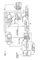
- Fig. 1 illustrates in block form a first embodiment of the spatial and temporal equalizer according to the present invention, which is an improvement of the prior art described previously with reference to Fig. 11.
- the equalizer of this embodiment basically includes an adaptive array antenna 10, a feed forward filter 22, an adaptive equalizer 23 and tap coefficient calculating parts 24 and 25 as is the case with the Fig. 11 prior art example.
- An array antenna 21 in the adaptive antenna array 10 corresponds to the antenna elements A 1 to A L in Fig. 11, and array antenna output combining part 28 corresponds to the multipliers M 1 to M L in Fig. 11 as described later on with respect to Fig. 2.
- the feed forward filter 22, the adaptive equalizer 23, and the tap coefficient calculating parts 24 and 25 correspond to the feed forward filter 14, the adaptive equalizer 11 and the tap coefficient calculating parts 16 and 17, respectively, in Fig. 11.
- the spatial and temporal equalizer according to this embodiment is newly provided with reception quality estimating part 26.
- tap coefficient select part 27 temporally switches between the respective tap coefficient calculating parts 24 and 25 so that tap coefficients of adaptive equalizer calculated therein are selectively set in the adaptive equalizer 23.
- the received signal is received by the array antenna 21 composed of L (where L is an integer equal to or greater than 2) elements, from which the received signal is provided as L sequences of array antenna output signals. These output signals are demodulated by L demodulators 20 in this embodiment.
- the demodulated signals S R are fed to array antenna output combining part 28.
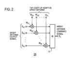
- Fig. 2 depicts an example of the array antenna output combining part 28.
- the L sequences of array antenna output signals S A1 to S AL input to the combining part 28 are complex-multiplied by tap coefficients of adaptive array antenna W A1 to W AL in multipliers M A1 to M AL , respectively. These multiplied signals are combined by an array antenna output combiner 12 into an array antenna combined signal S C .
- the array antenna combined signal S C is input to the feed forward filter 22.
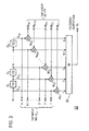
- Fig. 3 depicts an example of the feed forward filter 22.
- the array antenna combined signal S C is fed to a series circuit of unit delay elements D 1 to D N-1 .
- the delay time of each unit delay element is set to 1/2 of the symbol transmission period T in this example.
- input and output signals S i1 to S iN of the delay elements D 1 to D N-1 are complex-multiplied by tap coefficients of feed forward filter W F1 to W FN in multipliers M F1 to M FN , respectively, and the multiplied outputs are combined by combiner 29 into a filtering output signal S F .
- the feed forward filter 22 is formed by an N-tap (where N is an integer equal to or greater than 2) transversal filter.
- the delay element input/output signals S i1 to S iN are provided as a tap input signal S t1 to the tap coefficient calculating part 25.
- Fig. 4A depicts an example of the adaptive equalizer 23.
- the illustrated configuration is called MLSE type and intended for the Maximum Likelihood Sequence Estimation.
- the adaptive equalizer 23 uses, as the replica generator 32, an M-tap (where M is an integer equal to or greater than 1) transversal filter.
- the symbol sequence candidate signals S SSC is provided as a tap input signal S t2 , which is fed to the tap coefficient calculating part 24 and 25.
- the difference between the replica signal SRPL and the filtering signal SF, which is the input signal to the adaptive equalizer 23 is calculated by a subtractor 34 to generate an estimation error signal ⁇ .
- the absolute value of the estimation error signal ⁇ is squared by a squarer 35, and the squared value
- the most likely symbol pattern that is obtained with the Viterbi algorithm is output from the maximum likelihood sequence estimator 31 for decoding the received signal.
- the input signal is received as burst signals, each of which has a frame configuration that starts with a training signal period, followed by a data period.
- a switch SW is driven to switch the input side of the replica generator 32 from the maximum likelihood estimator 31 to a training signal memory 36, from which a training signal S TR of a predetermined symbol sequence is provided to the replica generator 32.
- the tap coefficient calculating part 24 performs tap coefficient convergence processing by which the tap coefficients for the adaptive array antenna 10, that is, the tap coefficients of adaptive array antenna W A1 to W AL corresponding to the multipliers M A1 to M AL , and the tap coefficients W E1 to W EM for the adaptive equalizer 23 are converged from initial values in accordance with the propagation path conditions through the use of an estimation error signal of the replica signal S RPL for the received signal S F filtered during the reception of the training signal, the array antenna output signal S R and the tap input signal S i2 , that is, the training signal.
- the tap coefficients W E1 to W EM and W A1 to W AL are converged in the training period so that the level of the estimation error signal, which is output from the adaptive equalizer 23, is reduced down to the lowest.
- the feed forward filter 22 is set to simply pass signals. This can be done by setting the tap coefficient of feed forward filter W F1 corresponding to the first tap to 1 and the other tap coefficients W F2 to W FN to 0s.
- ⁇ a forgetting coefficient equal to or smaller than 1
- U (i) is a vector composed of tap input signals S R and S t2
- P (i) is a correlation matrix of U (i)
- ⁇ *(i) is representative of the estimation error signal ⁇ .
- H represents a complex conjugate transpose.
- one of the tap coefficients of adaptive equalizer W E1 to W EM is fixed at 1 and the other remaining tap coefficients of adaptive equalizer are subjected to the convergence processing.
- the tap coefficients are expressed by a recurrence relation.
- the tap coefficients W converges with a successive increase in the value i.
- the tap coefficients W can be obtained recursively by inputting the input signal and the estimation error.
- the tap coefficient calculating part 25 performs tap coefficient convergence processing for the tap coefficients of feed forward filter W F1 to W FN and the tap coefficients of adaptive equalizer W E1 to W EM through the use of the estimation error signal ⁇ , the tap input signal S t1 (the received signals S i1 to S iN ) and the tap input signal S t2 (the training signal S TR ).
- This convergence processing also uses Eqs. (1) to (4) to converge the tap coefficients W F1 to W FN and W E1 to W EM in the training signal period to minimize the level of the estimation error signal that is output from the adaptive equalizer 23.
- P (i) is an inverse matrix of the correlation matrix of the tap input signals S t1 which is provided from the feed forward filter 22 and the tap input signal S t2 which is provided from the adaptive equalizer 23.
- the tap coefficients of adaptive array antenna W A1 to W AL are fixed to the values that are calculated at the end of the tap coefficient convergence processing in the tap coefficient calculating part 24.
- the initial values of the tap coefficients of adaptive equalizer W E1 to W EM can be converged fast by using the last computed values in the tap coefficient convergence processing.
- the results of the convergence of the adaptive equalization coefficients W E1 to W EM by the tap coefficient calculating part 24 are passed to the tap coefficient calculating part 25 for further convergence.
- the tap coefficient select part 27 is switched temporally to the tap coefficient calculating part 25 side.
- the receiving quality estimating part 26 first evaluates the magnitude of the estimation error signal that is output from the adaptive equalizer 23. Then, when the magnitude of the estimation error signal can be decided to be sufficiently small as compared with the received signal power, the estimating part 26 decides that the convergence of the tap coefficients has been completed, and outputs a receiving quality estimation signal that completes the tap coefficient convergence in the training signal period.
- the criterion of assessment or threshold value is chosen according to the propagation path conditions, for example, under -20 or -30 dB relative to the received signal power. That is, for example, when the SN ratio is relatively poor, there is a limit to reducing the estimation error signal.
- the receiving power can be substituted, for example, in the MLSE type equalizer of Fig. 4, with the output power of the replica generator 32. In a decision feedback type equalizer of Fig. 9, the receiving power needs only to be set at 1 since the tap coefficients are controlled so that the desired wave receiving power is 1.
- the receiving quality estimating part 26 outputs a receiving quality estimating signal S Q instructing to perform the tap coefficient convergence processing again by the use of the training signal.
- the tap coefficient calculating part 24 and 25 respond to the signal S Q to carry out the tap coefficient convergence processing in the training signal period, again.
- the initial values of the tap coefficients of adaptive array antenna, tap coefficients of feed forward filter and tap coefficients of adaptive equalizer are the values calculated at the end of the previous tap coefficient convergence processing in the tap coefficient calculating part 24 and 25.
- the above-described tap coefficient convergence processing by the tap coefficient calculating part 24 and 25 are repeated until it is decided that the tap coefficient convergence has been completed.
- the receiving quality estimating part 28 provides, as the receiving quality estimation signal, for example, (1, 0) for the tap coefficient convergence by the tap coefficient calculating part 24, (0, 1) for the tap convergence by the tap convergence calculating part 25, and (1, 1) for indicating the completion of the tap coefficient convergence processing.
- the tap coefficient calculating part 24 starts processing and the tap coefficient calculating part 25 stops processing; when the receiving signal quality estimation signal (0, 1) is provided, the tap coefficient calculating part 24 stops processing and the tap coefficient calculating part 25 starts processing; and when the receiving quality estimation signal (1, 1) is provided, the tap coefficient calculating part 24 and 25 perform the tap coefficient calculating processing, using the symbol sequence candidate signals from the adaptive equalizer 23 for the data signal period.
- the tap coefficient calculating part 24 and 25 repeat the tap coefficient convergence processing until the estimation error signal goes below the aforementioned criterion of assessment.
- storage part 29 is provided as a buffer. On a burst signal being received, demodulated outputs of L antenna element outputs from the demodulator 20 are stored in the storage part 29. For the tap coefficient convergence processing it is possible to repeatedly use the received training signal stored in the storage part 29. This avoids the necessity for using a training signal of a particularly long duration. Decode processing of the data period after the tap coefficient convergence processing is also carried out using the received signal stored in the storage part 29.
- the training signal period may be split into two; the first half period is for the coefficient calculating part 24 and the second half period is for the coefficient calculating part 25.
- the training signal period may be split into four, in which case the four quarter periods are sequentially assigned to the coefficient calculating part 24 and 25 alternately with each other.
- the coefficient convergence processing by the tap coefficient calculating part 25 is followed by deciding whether the magnitude of the estimation error signal has become smaller than the predetermined value, and the convergence processing by the coefficient calculating part 24 and 25 is repeated until the estimation error signal becomes smaller than the predetermined value.
- the input of the replica generator 32 (Fig. 4A) is switched to the maximum likelihood estimator 31, followed by starting the processing in the data signal period.
- temporal variations of the direction of incoming signals are slower than the temporal variations of the propagation path.
- the tap coefficients of adaptive array antenna W A1 to W AL are fixed to the values calculated at the end of the tap coefficient convergence processing by the tap coefficient calculating part 24, and only the tap coefficients of feed forward filter W F1 to W FN and the tap coefficients of adaptive equalizer W E1 to W EM are updated, by which the temporal variations of the direction of incoming signals are made to follow the temporal variations of the propagation path.
- the adaptive equalizer 23 outputs a decided symbol signal and the received signal is decoded accordingly.
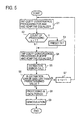
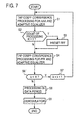
- Fig. 5 is a flowchart showing an example of the spatial and temporal equalization procedure of the first embodiment of the invention.
- Fig. 6 shows the procedure to be followed in such a case.
- step S10 is provided after step S7 in Fig. 5 to determine whether the number of counts, k, of processing is smaller than the predetermined value K; if smaller, the procedure returns to step S1, and if not smaller, the procedure goes to step S11 to request the transmitting side to resend the signal.
- step S6 instead of deciding in step S6 whether the estimation error is smaller than the predetermined value, it is possible to decide whether the convergence processing has been repeated a predetermined number of times K more than twice as shown by the step S6' in Fig. 7 and, if not, return to step S1 via step S7 and repeat the processing.
- the same training signal can be used in the tap coefficient calculating part 24 and 25.
- the training signal period of the demodulated signal stored in the storage part 29 is repeatedly used; the entire length of the training signal is shorter than in the case of using a different training signal in each tap coefficient calculating part. This is advantageous in terms of information transmission efficiency.
- the symbol timing for demodulation is made to coincide with the timing of the leading wave of the received signal.
- the above-mentioned timing is taken as time 0 (i.e., current time point) and a replica signal is generated from a symbol candidates at time 0 and past or previous symbol candidates (-T, -2T, ...) for equalization.
- Fig. 8 shows the configuration of a replica generator designed to prevent the deterioration of the receiving characteristic due to such symbol timing offset.
- the M taps are supplied with symbol candidates S 1 , S 2 , ..., S M corresponding to the time points in time 0, -T, -2T, ..., -(M-1)T, respectively.
- S 1 , S 2 , ..., S M corresponding to the time points in time 0, -T, -2T, ..., -(M-1)T, respectively.
- M taps are supplied with symbol candidates S 1 , S 2 , ..., S M corresponding to the time points in time +m 1 T, ..., +T, 0, -T, -2T, ..., -(m 2 -1)T, then these symbol candidates are multiplied by M tap coefficients of adaptive equalizer W E1 to W EM by M multipliers M E1 to M EM , respectively, and the multiplied outputs are added together by an adder 33 to obtain the replica signal S RPL .
- M m 1 +m 2 , where m 1 and m 2 are integers equal to or greater than one, and m 1 symbol candidates at the times T, 2T, ..., m 1 T correspond to future signals.
- the future symbol candidates can easily be generated since the symbol pattern is known. Further, according to this embodiment, even if symbol components at future time points are contained as intersymbol interference in the received signal, it is possible to generate the replica signal with accuracy and hence improve the receiving characteristic.
- step (a) in the case where the values of tap coefficients on the future side are found sufficiently small after step (a) and it is decided that there is no interference by the future symbols due to symbol timing offset, it is possible to stop containing the future symbols in the replica in the subsequent processing. This permits reduction of the computational complexity.
- step (a) in the case where the value of tap coefficients on the future side are found larger than a certain value after step (a) and it can be decided that there is interference by the future symbols due to symbol timing offset, it is possible to adjust the symbol timing to suppress the interference by the future symbols. It is also possible to perform step (a) after adjustment of the symbol timing; that is, it is possible to repeat the symbol timing adjustment and the step (a) until the value of the tap coefficients on the future side become sufficiently small.
- the feed forward filter 22 since the feed forward filter 22 has a symbol timing offset adjustment capability, it is possible to automatically adjust the symbol timing offset in the feed forward filter 22 by excluding the future symbols from the replica generation by the adaptive equalizer. This eliminates the necessity for containing future symbols in the replica in the subsequent processing.
- a decision feedback equalizer can be used as the adaptive equalizer 23 in the Fig. 1 embodiment.
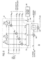
- Fig. 9 illustrates an example of its configuration.
- a fed-back version of the decided symbol signal is used in place of the symbol candidate signal used in the maximum likelihood estimation type equalizer. That is, a replica of delayed components of received symbols prior to the current received symbol is generated by a replica generator 32', then the replica of the delayed components is subtracted by an adder 34A from the filtering output signal (received signal) S F fed from the feed forward filter 22, and it is decided by a decision device 42 whether the output from the adder 34A is 1 or 0.
- This decision result is output as a decoded symbol, and it is input to a series circuit of unit delay elements D U1 to D UM-1 each having a delay time of one symbol period T.
- the output signals from the delay elements D U1 to D UM-1 are complex-multiplied by tap coefficients of adaptive equalizer W E1 to W EM-1 by multipliers M E1 to M EM-1 , respectively.
- the multiplied outputs are combined by the combiner 33, and the delayed components of the received symbols prior to the current one due to the propagation path are estimated, after which the combined output is provided to the subtractor 34A.
- the replica of the delayed components of the received symbols preceding the current one is generated by the delay elements D U1 to D UM-1 , the multipliers M E1 to M EM-1 and the combiner 33 that constitute the replica generator 32'.
- the output signals from the delay elements D U1 to D UM-1 are used as the tap input signal S t2 , which is applied to the tap coefficient calculating part 24 and 25 in Fig. 1.
- the difference between the input and output signals of the decision device 42 is calculated by a subtractor 34B and is used as the estimation error signal ⁇ .
- the replica generator 32' in the Fig. 9 embodiment generates a replica using only symbols at previous points in time, that is, the outputs from the delay elements D U1 to D UM-1 ; the replica generator is shown to have M-1 taps only for the purpose of comparison with the case of Fig. 4, but this value has no particular meaning and the number of taps is arbitrary.
- the weighting of the adaptive array antenna is performed for the demodulated output, it may also be done for an RF signal.
- the signal to be input to the tap coefficient calculating part 24 needs to be demodulated separately. That is, in Fig. 1 the L demodulators 20 at the output side of the array antenna 20 are removed, one demodulator is connected to the output side of the array antenna output signal combining part 28 and L demodulators are inserted in the signal line from the array antenna 21 to the tap coefficient calculating part 24.
- the storage part 29 stores the RF signal, it is rather practical to split the training period than to repeatedly use the same training period.
- Fig. 9 may also be combined with the second embodiment of Fig. 8.
- the array antenna output combining part 28 in Fig. 2, the feed forward filter 22 in Fig. 3, the replica generator 32 in Figs. 4 and 8 and adaptive equalizer 23 in Fig. 9 each have been described to have multipliers of the same number as that of the tap coefficients and perform multiplying operations at the same time, but it is also possible to conduct the multiplying operations one after another by repeatedly actuating only one multiplier instead of using so many multipliers.
- the present invention permits implementation of a simple-structured spatial and temporal equalizer. Even if the tap coefficient calculation processing is performed for each of the adaptive array antenna, the feed forward filter and the adaptive equalizer, sufficient convergence of tap coefficients can be achieved without requiring significantly large computational complexity, and hence it is possible to attain the same level of receiving characteristic as is obtainable with a more complicated structure for batch processing.
Landscapes
- Engineering & Computer Science (AREA)
- Computer Networks & Wireless Communication (AREA)
- Signal Processing (AREA)
- Cable Transmission Systems, Equalization Of Radio And Reduction Of Echo (AREA)
- Radio Transmission System (AREA)
- Variable-Direction Aerials And Aerial Arrays (AREA)
Abstract
Description
Claims (16)
- A spatial and temporal equalizer comprising:an adaptive array antenna which complex-multiplies array antenna output signals from an array antenna composed of L elements by tap coefficients of adaptive array antenna to control the amplitudes and phases of received signals, and combines the multiplied output signals into an array antenna composite signal, said L being an integer equal to or greater than 2;a feed forward filter comprising a transversal filter of N taps respectively weighted by tap coefficients of feed forward filter, for receiving said array antenna composite signal and outputting signals of the N taps as a first tap input signal and a filtering output signal, said N being an integer equal to or greater than 2;an adaptive equalizer which has a replica generator of M taps respectively weighted by tap coefficients of adaptive equalizer, outputs, as a second tap input signal, signals from the M taps of said replica generator supplied with symbol sequences, and outputs an estimation error signal for a received symbol based on the output from said adaptive equalization circuit and a decision symbol signal, said M being an integer equal to or greater than 1;first tap coefficient calculating means for calculating said tap coefficients of adaptive array antenna and said tap coefficients of adaptive equalizer from said array antenna output signal, said second tap input signal and said estimation error signal;second tap coefficient calculating means for calculating said tap coefficients of feed forward filter and said tap coefficients of adaptive equalizer from said first and second tap input signals and said estimation error signal;tap coefficient select means for selectively outputting either said tap coefficients of adaptive equalizer from said first tap coefficient calculating means or said tap coefficients of adaptive equalizer from said second tap coefficient calculating means; andreceiving quality estimating means for causing said first and second tap coefficient calculating means to repeat their convergence operation until it is estimated that the receiving quality has reached a desired level.
- The spatial and temporal equalizer of claim 1, wherein said receiving quality estimating means is a means for deciding whether said receiving quality has reached a predetermined level by making a check to see if said estimation error signal is smaller than a predetermined value.
- The spatial and temporal equalizer of claim 1, wherein said receiving quality estimating means is a means for deciding that said receiving quality has reached a predetermined level by repeating convergence operations of said first and second tap coefficient calculating means twice or a predetermined larger number of times.
- The spatial and temporal equalizer of claim 1, wherein said replica generator comprises: M multipliers supplied with symbol sequences, for multiplying these symbols by said tap coefficients of adaptive equalizer, respectively; and a combiner for combining the multiplied outputs from said M multipliers to provide the combined output as a replica for said received symbols; and said adaptive equalizer comprises: a subtractor for outputting the difference between said filtering output signal and said replica as said estimation error signal; a maximum likelihood estimator for generating a symbol sequence candidate, for making a maximum likelihood estimation based on said estimation error signal to output a decision symbol; a training signal memory with a predetermined symbol sequence stored as a training signal; and a switch which selects said training signal read out of said training signal memory in a training signal period of a received signal, selects said symbol sequence candidate from said maximum likelihood estimator in a data signal period of said received signal and provides said selected symbol sequence candidate to said replica generator, and provides said selected symbol sequence candidate as said first tap input signal to said first and second tap coefficient calculating means.
- The spatial and temporal equalizer of claim 4, wherein said maximum likelihood estimator generates, as said symbol sequence candidate, a symbol sequence composed of M symbols preceding the current point in time.
- The spatial and temporal equalizer of claim 4, wherein let m1 and m2 be integers equal to or greater than 1, said maximum likelihood estimator generates, as said symbol sequence candidate, a symbol sequence composed of a total of M symbols including m1 future symbols and m2 symbols covering from current time point to a past time point.
- The spatial and temporal equalizer of claim 1, wherein said replica generator comprises: a plurality of cascade-connected delay elements each having a delay time equal to a symbol period; a plurality of multipliers for multiplying the outputs from said delay elements by said tap coefficients of adaptive equalizer, respectively; a combiner for combining the outputs from said multipliers; a first subtractor for providing the difference between the output from said combiner and said filtering output signal; a decision device for deciding the level of the output from said first subtractor to output said decision symbol; a second subtractor for providing the difference between said decision symbol and said first subtractor output as said estimation error signal; a training signal memory for storing a training signal of a predetermined symbol sequence; and a switch which sequentially selects symbols of said training signal from said training signal memory in a training signal period of a received signal, selects said decision symbol in a data signal period of said received signal, and provides selected symbols to said cascade connection of said delay elements.
- The spatial and temporal equalizer of any one of claims 4 to 7, wherein said adaptive array antenna comprises demodulators for demodulating received signals from said L-element array antenna, and array antenna output combining means which complex-multiplies the demodulated outputs from said demodulators by said tap coefficients of adaptive array antenna, combines the multiplied outputs into said array antenna composite signal.
- The spatial and temporal equalizer of claim 8, which further comprises received signal storage means for temporarily storing the demodulated received signals of said demodulators, and wherein processing by said first and second tap coefficient calculating means is performed for demodulated signals read out of said received signal storage means.
- The spatial and temporal equalizer of any one of claims 2 to 7, wherein said adaptive array antenna comprises array antenna output combining means for complex-multiplying received signal from said L-element array antenna by said tap coefficients of adaptive array antenna and for combining the multiplied outputs, and a demodulator for demodulating the combined output and for outputting the demodulated output as said array antenna composite signal.
- The spatial and temporal equalizer of claim 10, which further comprises received signal storage means for temporarily storing received signals from said array antenna, and wherein processing by said first and second tap coefficient calculating means is performed for received signals ad out of said received signal storage means.
- A spatial and temporal equalization method which compensates for symbol timing offset in the output from an adaptive array antenna having array antennas by a feed forward filter and makes a symbol decision by an adaptive equalizer, said method comprising the steps of:(a) calculating tap coefficients of adaptive array antenna for the outputs from said array antennas and tap coefficients of adaptive equalizer for said adaptive equalizer based on received signals from said array antennas and a first tap input signal and an estimation error signal from said adaptive equalizer;(b) calculating tap coefficients of feed forward filter for respective taps of said feed forward filter and said tap coefficients of adaptive equalizer for said adaptive equalizer from a second tap input signal provided from tap outputs of said feed forward filter, said first tap input signal and said estimation error signal;(c) calculating an estimation error in said adaptive equalizer through the use of said tap coefficients of adaptive array antenna, said tap coefficients of feed forward filter and said tap coefficients of adaptive equalizer calculated by said steps (a) and (b); and(d) deciding whether said estimation error is smaller than a predetermined value, and if not smaller, repeating said steps (a) and (b).
- A spatial and temporal equalization method which compensates for symbol timing offset in the output from an adaptive array antenna having array antennas by a feed forward filter and makes a symbol decision by an adaptive equalizer, said method comprising the steps of:(a) calculating tap coefficients of adaptive array antenna for the outputs from said array antennas and tap coefficients of adaptive equalizer for said adaptive equalizer based on received signals from said array antennas and a first tap input signal and an estimation error signal from said adaptive equalizer;(b) calculating tap coefficients of feed forward filter for respective taps of said feed forward filter and said tap coefficients of adaptive equalizer for said adaptive equalizer from a second tap input signal provided from tap outputs of said feed forward filter, said first tap input signal and said estimation error signal; and(c) deciding whether the number of repetitions of said steps (a) and (b) has reached a predetermined value larger than 2, and if not, repeating said steps (a) and (b).
- The spatial and temporal equalization method of claim 12 or 13, wherein said steps (a) and (b) are steps of performing operations in first and second halves of a training signal period of a received signal.
- The spatial and temporal equalization method of claim 12 or 13, which further comprises a step of storing a burstwise received signal in storage means, and wherein said steps (a) and (b) are steps of reading out the same training signal period of the received signal from said storage means and performing operations.
- The spatial and temporal equalization method of claim 12 or 13, wherein: during the tap coefficient convergence processing in said step (a) said feed forward filter is set in its simply-passing state; and during the second tap coefficient convergence processing in said step (b) said tap coefficients of adaptive array antenna calculated in said step (a) are fixed, said tap coefficients of adaptive equalizer are set at initial values and said tap coefficients of feed forward filter and said tap coefficients of adaptive equalizer are calculated.
Applications Claiming Priority (2)
| Application Number | Priority Date | Filing Date | Title |
|---|---|---|---|
| JP2000085778 | 2000-03-27 | ||
| JP2000085778 | 2000-03-27 |
Publications (3)
| Publication Number | Publication Date |
|---|---|
| EP1158694A2 true EP1158694A2 (en) | 2001-11-28 |
| EP1158694A3 EP1158694A3 (en) | 2002-10-02 |
| EP1158694B1 EP1158694B1 (en) | 2009-01-28 |
Family
ID=18602043
Family Applications (1)
| Application Number | Title | Priority Date | Filing Date |
|---|---|---|---|
| EP01107554A Expired - Lifetime EP1158694B1 (en) | 2000-03-27 | 2001-03-27 | Spatial and temporal equalizer and equalization method |
Country Status (4)
| Country | Link |
|---|---|
| US (1) | US6862316B2 (en) |
| EP (1) | EP1158694B1 (en) |
| CN (1) | CN1169383C (en) |
| DE (1) | DE60137559D1 (en) |
Families Citing this family (37)
| Publication number | Priority date | Publication date | Assignee | Title |
|---|---|---|---|---|
| FR2813728B1 (en) * | 2000-09-07 | 2003-03-07 | Mitsubishi Electric Inf Tech | BI-MODULAR ADAPTIVE CDMA RECEIVER |
| JP2002344362A (en) * | 2001-05-14 | 2002-11-29 | Hitachi Kokusai Electric Inc | Equalization device, reception device, equalization method, and reception method |
| US7035343B2 (en) * | 2002-01-31 | 2006-04-25 | Qualcomm Inc. | Closed loop transmit diversity antenna verification using trellis decoding |
| US7099409B2 (en) * | 2002-02-13 | 2006-08-29 | Broadcom Corporation | Channel estimation and/or equalization using repeated adaptation |
| KR100878524B1 (en) * | 2002-05-21 | 2009-01-13 | 삼성전자주식회사 | Filter tap coefficient update device and update method of equalizer |
| KR100467317B1 (en) * | 2002-05-22 | 2005-01-24 | 한국전자통신연구원 | Scalable adaptive equalizer |
| EP1376896A1 (en) * | 2002-06-20 | 2004-01-02 | Evolium S.A.S. | Iterative channel estimation for receiving wireless transmissions using multiple antennas |
| AU2003262848A1 (en) * | 2002-08-21 | 2004-03-11 | Zyray Wireless, Inc. | Antenna array including virtual antenna elements |
| US8457230B2 (en) | 2002-08-21 | 2013-06-04 | Broadcom Corporation | Reconfigurable orthogonal frequency division multiplexing (OFDM) chip supporting single weight diversity |
| US7039104B2 (en) * | 2002-11-08 | 2006-05-02 | Scintera Networks, Inc. | Adaptive coefficient signal generator for adaptive signal equalizers with fractionally-spaced feedback |
| US6940898B2 (en) * | 2002-11-08 | 2005-09-06 | Scintera Networks, Inc. | Adaptive coefficient signal generator for adaptive signal equalizers with fractionally-spaced feedback |
| US7035330B2 (en) * | 2002-12-17 | 2006-04-25 | Scintera Networks, Inc. | Decision feedback equalizer with dynamic feedback control |
| US7120193B2 (en) * | 2002-11-08 | 2006-10-10 | Scintera Networks, Inc. | Decision feedback equalizer with dynamic feedback control |
| US7813440B2 (en) * | 2003-01-31 | 2010-10-12 | Ntt Docomo, Inc. | Multiple-output multiple-input (MIMO) communication system, MIMO receiver and MIMO receiving method |
| US7272176B2 (en) * | 2003-02-18 | 2007-09-18 | Qualcomm Incorporated | Communication receiver with an adaptive equalizer |
| US20050053127A1 (en) * | 2003-07-09 | 2005-03-10 | Muh-Tian Shiue | Equalizing device and method |
| KR20050027785A (en) * | 2003-09-16 | 2005-03-21 | 삼성전자주식회사 | Method for detecting signal quality and apparatus therefor and recording medium for recording programs for realizing the same |
| CN1297075C (en) * | 2003-12-02 | 2007-01-24 | 中国人民解放军空军雷达学院 | Interference blocking spatial spectrum estimation method |
| EP1768263B1 (en) * | 2004-05-26 | 2015-01-21 | NEC Corporation | Spatially-multiplexed signal detecting method and time space iterative decoder using same |
| US7436615B2 (en) * | 2005-12-08 | 2008-10-14 | International Business Machines Corporation | Using a measured error to determine coefficients to provide to an equalizer to use to equalize an input signal |
| JP2007195075A (en) * | 2006-01-20 | 2007-08-02 | Fujitsu Ltd | Demodulation circuit and demodulation method |
| KR101133839B1 (en) * | 2006-02-13 | 2012-04-06 | 에스티 에릭슨 에스에이 | Filter weight estimation device with update at hsdsch symbol rate, for a symbol level equaliser |
| US20090135944A1 (en) * | 2006-10-23 | 2009-05-28 | Dyer Justin S | Cooperative-MIMO Communications |
| KR100902336B1 (en) * | 2007-07-20 | 2009-06-12 | 한국전자통신연구원 | Co-channel repeater and method |
| JP2009135712A (en) * | 2007-11-29 | 2009-06-18 | Kyocera Corp | Receiving apparatus, radio base station, and receiving method |
| JP4573361B2 (en) * | 2008-08-22 | 2010-11-04 | 京セラ株式会社 | Wireless communication apparatus and wireless communication method |
| GB2494204B (en) * | 2011-09-05 | 2017-05-24 | Roke Manor Research | Method and apparatus for signal detection |
| US8559496B1 (en) * | 2012-06-20 | 2013-10-15 | MagnaCom Ltd. | Signal reception using non-linearity-compensated, partial response feedback |
| US9112742B2 (en) * | 2013-05-15 | 2015-08-18 | Futurewei Technologies, Inc. | Low-complexity, adaptive, fractionally spaced equalizer with non-integer sampling |
| US10303146B2 (en) | 2017-05-31 | 2019-05-28 | Oracle International Corporation | Servomechanism error handling |
| CN108063738B (en) * | 2017-11-22 | 2020-08-25 | 西南电子技术研究所(中国电子科技集团公司第十研究所) | Convergence decision method for digital equalizer |
| CN113783811A (en) * | 2020-06-10 | 2021-12-10 | 英业达科技有限公司 | Method and device for calculating joint coefficient |
| CN115943569A (en) * | 2020-06-23 | 2023-04-07 | 马维尔亚洲私人有限公司 | Context-aware run-time configuration of filters in high-speed data channels |
| JP7495637B2 (en) * | 2020-08-24 | 2024-06-05 | 日本電信電話株式会社 | Symbol decision device and tap selection method |
| JP7824289B6 (en) * | 2020-10-23 | 2026-04-06 | インフィニオン テクノロジーズ アメリカズ コーポレーション | Equalization on high-speed data channels with sparsity impulse response |
| CN112887236B (en) * | 2021-01-12 | 2021-09-21 | 烽火通信科技股份有限公司 | Synchronization and equalization device and method for high-speed burst signal |
| CN116208292B (en) * | 2021-11-30 | 2025-12-23 | 中兴通讯股份有限公司 | Signal processor optimizing method, signal processor and computer readable storage medium |
Family Cites Families (12)
| Publication number | Priority date | Publication date | Assignee | Title |
|---|---|---|---|---|
| US6166689A (en) * | 1970-08-12 | 2000-12-26 | Lockheed Martin Corporation | Adaptive beamformer with beam mainlobe maintenance |
| JP2663820B2 (en) | 1992-12-28 | 1997-10-15 | 日本電気株式会社 | Decision feedback equalizer |
| JP2697648B2 (en) * | 1994-12-26 | 1998-01-14 | 日本電気株式会社 | Decision feedback equalizer |
| EP0846378B1 (en) * | 1995-08-22 | 1999-10-06 | Thomson-Csf | Method and device for spatial multiplexing-demultiplexing of radio signals for an sdma mobile radio system |
| FR2742619B1 (en) * | 1995-12-15 | 1998-02-06 | Thomson Csf | MULTI-SENSOR EQUALIZATION METHOD FOR MULTI-SENSOR RECEPTION IN THE PRESENCE OF INTERFERENCE AND MULTI-TRAVEL PATHWAYS, AND RECEIVER FOR IMPLEMENTING SAME |
| WO1997044855A1 (en) | 1996-05-20 | 1997-11-27 | Post Und Telekom Austria Aktiengesellschaft | Process and device for reception with directional resolution |
| US5870430A (en) * | 1996-12-26 | 1999-02-09 | Thomson-Csf | Process for multi-sensor equalisation in a radio receiver in the presence of interference and multiple propagation paths |
| FR2758926B1 (en) * | 1997-01-24 | 1999-04-30 | France Telecom | METHOD OF MULTI-SENSOR EQUALIZATION IN A RADIOELECTRIC RECEIVER HAVING A DETERMINED NUMBER OF RECEPTION PATHWAYS AND CORRESPONDING RECEIVER |
| KR100312836B1 (en) * | 1997-06-03 | 2001-12-28 | 다치카와 게이지 | Adaptive array transceiver |
| JP3465739B2 (en) * | 1998-04-07 | 2003-11-10 | 日本電気株式会社 | CDMA adaptive antenna receiving apparatus and communication system |
| US6115409A (en) * | 1999-06-21 | 2000-09-05 | Envoy Networks, Inc. | Integrated adaptive spatial-temporal system for controlling narrowband and wideband sources of interferences in spread spectrum CDMA receivers |
| US6317467B1 (en) * | 2000-06-14 | 2001-11-13 | Lloyd C. Cox | Beamforming and interference cancellation system using general purpose filter architecture |
-
2001
- 2001-03-27 US US09/817,348 patent/US6862316B2/en not_active Expired - Fee Related
- 2001-03-27 CN CNB01116493XA patent/CN1169383C/en not_active Expired - Fee Related
- 2001-03-27 EP EP01107554A patent/EP1158694B1/en not_active Expired - Lifetime
- 2001-03-27 DE DE60137559T patent/DE60137559D1/en not_active Expired - Lifetime
Also Published As
| Publication number | Publication date |
|---|---|
| US20010026197A1 (en) | 2001-10-04 |
| DE60137559D1 (en) | 2009-03-19 |
| EP1158694B1 (en) | 2009-01-28 |
| EP1158694A3 (en) | 2002-10-02 |
| US6862316B2 (en) | 2005-03-01 |
| CN1169383C (en) | 2004-09-29 |
| CN1316861A (en) | 2001-10-10 |
Similar Documents
| Publication | Publication Date | Title |
|---|---|---|
| EP1158694B1 (en) | Spatial and temporal equalizer and equalization method | |
| US5127051A (en) | Adaptive modem for varying communication channel | |
| AU691953B2 (en) | Method of and apparatus for interference rejection combining in multi-antenna digital cellular communications systems | |
| JP3375139B2 (en) | Adaptive array transceiver | |
| KR20000005543A (en) | Method and apparatus for interference rejection with different beams, polarizations, and phase references | |
| KR20080081029A (en) | Interference Cancellation in Telecommunication Systems | |
| EP1217798B1 (en) | Adaptive equalization method and adaptive equalizer | |
| JP3235774B2 (en) | Adaptive array receiver | |
| JP3866049B2 (en) | Time-space equalization apparatus and equalization method | |
| JP3808311B2 (en) | Reception method and receiver | |
| JPH11261457A (en) | Waveform equalization processing method | |
| JP3256646B2 (en) | Adaptive interference cancellation receiver | |
| JP3424723B2 (en) | Adaptive equalizer | |
| JP3061108B2 (en) | Receiving device and receiving method | |
| JP2000341183A (en) | Receiver | |
| JP4187968B2 (en) | Adaptive equalization method and adaptive equalizer | |
| JP2001196978A (en) | Adaptive equalization system, diversity reception system, and adaptive equalizer | |
| JP3436647B2 (en) | Diversity receiver and diversity receiving method | |
| JP3739597B2 (en) | Radio receiving apparatus and equalization processing method | |
| JP3424724B2 (en) | Interference canceller | |
| JP3138586B2 (en) | Adaptive equalizer and adaptive diversity equalizer | |
| JP3537203B2 (en) | Antenna diversity receiver | |
| JP2846958B2 (en) | Adaptive demodulation method for generating replica and demodulator using same | |
| JP3379066B2 (en) | Adaptive equalizer and gain vector estimator used for it | |
| JP2591241B2 (en) | Adaptive diversity receiver |
Legal Events
| Date | Code | Title | Description |
|---|---|---|---|
| PUAI | Public reference made under article 153(3) epc to a published international application that has entered the european phase |
Free format text: ORIGINAL CODE: 0009012 |
|
| 17P | Request for examination filed |
Effective date: 20010327 |
|
| AK | Designated contracting states |
Kind code of ref document: A2 Designated state(s): AT BE CH CY DE DK ES FI FR GB GR IE IT LI LU MC NL PT SE TR |
|
| AX | Request for extension of the european patent |
Free format text: AL;LT;LV;MK;RO;SI |
|
| PUAL | Search report despatched |
Free format text: ORIGINAL CODE: 0009013 |
|
| AK | Designated contracting states |
Kind code of ref document: A3 Designated state(s): AT BE CH CY DE DK ES FI FR GB GR IE IT LI LU MC NL PT SE TR |
|
| AX | Request for extension of the european patent |
Free format text: AL;LT;LV;MK;RO;SI |
|
| RIC1 | Information provided on ipc code assigned before grant |
Free format text: 7H 04B 7/08 A, 7H 04B 7/005 B, 7H 04L 25/03 B |
|
| AKX | Designation fees paid |
Designated state(s): DE FR GB IT SE |
|
| 17Q | First examination report despatched |
Effective date: 20060512 |
|
| REG | Reference to a national code |
Ref country code: SE Ref legal event code: TRGR |
|
| GRAP | Despatch of communication of intention to grant a patent |
Free format text: ORIGINAL CODE: EPIDOSNIGR1 |
|
| GRAS | Grant fee paid |
Free format text: ORIGINAL CODE: EPIDOSNIGR3 |
|
| GRAA | (expected) grant |
Free format text: ORIGINAL CODE: 0009210 |
|
| AK | Designated contracting states |
Kind code of ref document: B1 Designated state(s): DE FR GB IT SE |
|
| REG | Reference to a national code |
Ref country code: GB Ref legal event code: FG4D |
|
| REF | Corresponds to: |
Ref document number: 60137559 Country of ref document: DE Date of ref document: 20090319 Kind code of ref document: P |
|
| PLBE | No opposition filed within time limit |
Free format text: ORIGINAL CODE: 0009261 |
|
| STAA | Information on the status of an ep patent application or granted ep patent |
Free format text: STATUS: NO OPPOSITION FILED WITHIN TIME LIMIT |
|
| 26N | No opposition filed |
Effective date: 20091029 |
|
| PGFP | Annual fee paid to national office [announced via postgrant information from national office to epo] |
Ref country code: IT Payment date: 20120321 Year of fee payment: 12 |
|
| PGFP | Annual fee paid to national office [announced via postgrant information from national office to epo] |
Ref country code: FR Payment date: 20130325 Year of fee payment: 13 Ref country code: DE Payment date: 20130320 Year of fee payment: 13 Ref country code: SE Payment date: 20130312 Year of fee payment: 13 Ref country code: GB Payment date: 20130327 Year of fee payment: 13 |
|
| REG | Reference to a national code |
Ref country code: DE Ref legal event code: R119 Ref document number: 60137559 Country of ref document: DE |
|
| REG | Reference to a national code |
Ref country code: SE Ref legal event code: EUG |
|
| GBPC | Gb: european patent ceased through non-payment of renewal fee |
Effective date: 20140327 |
|
| PG25 | Lapsed in a contracting state [announced via postgrant information from national office to epo] |
Ref country code: SE Free format text: LAPSE BECAUSE OF NON-PAYMENT OF DUE FEES Effective date: 20140328 |
|
| REG | Reference to a national code |
Ref country code: FR Ref legal event code: ST Effective date: 20141128 |
|
| REG | Reference to a national code |
Ref country code: DE Ref legal event code: R119 Ref document number: 60137559 Country of ref document: DE Effective date: 20141001 |
|
| PG25 | Lapsed in a contracting state [announced via postgrant information from national office to epo] |
Ref country code: DE Free format text: LAPSE BECAUSE OF NON-PAYMENT OF DUE FEES Effective date: 20141001 Ref country code: GB Free format text: LAPSE BECAUSE OF NON-PAYMENT OF DUE FEES Effective date: 20140327 Ref country code: FR Free format text: LAPSE BECAUSE OF NON-PAYMENT OF DUE FEES Effective date: 20140331 |
|
| PG25 | Lapsed in a contracting state [announced via postgrant information from national office to epo] |
Ref country code: IT Free format text: LAPSE BECAUSE OF NON-PAYMENT OF DUE FEES Effective date: 20140327 |