EP1158621A2 - A connector housing - Google Patents
A connector housing Download PDFInfo
- Publication number
- EP1158621A2 EP1158621A2 EP01109960A EP01109960A EP1158621A2 EP 1158621 A2 EP1158621 A2 EP 1158621A2 EP 01109960 A EP01109960 A EP 01109960A EP 01109960 A EP01109960 A EP 01109960A EP 1158621 A2 EP1158621 A2 EP 1158621A2
- Authority
- EP
- European Patent Office
- Prior art keywords
- retainer
- locking position
- partial
- partial locking
- main body
- Prior art date
- Legal status (The legal status is an assumption and is not a legal conclusion. Google has not performed a legal analysis and makes no representation as to the accuracy of the status listed.)
- Granted
Links
Images




Classifications
-
- H—ELECTRICITY
- H01—ELECTRIC ELEMENTS
- H01R—ELECTRICALLY-CONDUCTIVE CONNECTIONS; STRUCTURAL ASSOCIATIONS OF A PLURALITY OF MUTUALLY-INSULATED ELECTRICAL CONNECTING ELEMENTS; COUPLING DEVICES; CURRENT COLLECTORS
- H01R13/00—Details of coupling devices of the kinds covered by groups H01R12/70 or H01R24/00 - H01R33/00
- H01R13/40—Securing contact members in or to a base or case; Insulating of contact members
- H01R13/42—Securing in a demountable manner
- H01R13/436—Securing a plurality of contact members by one locking piece or operation
- H01R13/4361—Insertion of locking piece perpendicular to direction of contact insertion
- H01R13/4362—Insertion of locking piece perpendicular to direction of contact insertion comprising a temporary and a final locking position
Definitions
- the present invention relates to a connector housing and is particularly designed to prevent an inadvertent movement of a retainer for doubly locking terminal fittings to a full locking position before the terminal fittings are inserted.
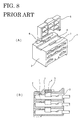
- a protection wall 7 extending to a height substantially the same as a pushing portion of the retainer 5 when the retainer 5 is in the partial locking position in the connector housing 1 shown in FIGS. 8(A) and 8(B).
- a connector housing comprising:
- the holding force for holding the retainer in first partial locking position in the housing main body is set at such a strength that the retainer is not pushed to the second partial locking position by collision of an other connector housing or an other external matter with this connector housing during transportation of the connector housings.
- the holding force of the retainer in the second partial locking position is set at such a strength that the retainer can be easily pushed to the full locking position by hands. Accordingly, the retainer is prevented from inadvertently moving to the full locking position while the connector housing is transported to a location where a terminal fitting inserting operation is performed.
- the retainer in the first partial locking position is inserted to the second partial locking position by a pushing means of an automatic apparatus during assembling of a subassembly by the automatic apparatus, and is finally pushed to the full locking position by hands after the terminal fittings are inserted in remaining positions by hands.
- the retainer is or can locked in the first partial locking position in the housing main body by a first locking means comprising one or more mutually engageable locking projections and locking holes preferably formed between the substantially opposite side walls of the retainer and those of the hollow portion or preferably formed on at least one side wall of the retainer and a corresponding wall of the hollow portion, and/or the retainer is or can be locked in the second partial locking position and the full locking position in the housing main body by a second locking means comprising one or more full and partial locking projections projecting from front and rear inner walls of the hollow portion in the housing main body and corresponding full and partial locking claws projecting from the retainer and selectively engageable with the full and partial locking projections in the full locking position and the second locking position.
- a first locking means comprising one or more mutually engageable locking projections and locking holes preferably formed between the substantially opposite side walls of the retainer and those of the hollow portion or preferably formed on at least one side wall of the retainer and a corresponding wall of the hollow portion
- the retainer is
- the first locking means removes a restriction on the movement of the retainer when the retainer is inserted to the second partial locking position.
- the holding force of the first locking means does not act after the retainer reaches the second partial locking position, with the result that the retainer can be easily and securely pushed from the second partial locking position to the full locking position.
- the partial locking claw of the retainer comes substantially into contact with the partial locking projection of the housing main body to additionally create a supplemental holding force for preventing the movement of the retainer in its inserting direction.
- the first locking means removes a restriction on the movement of the retainer when the retainer is inserted to the second partial locking position.
- the full locking claw of the retainer comes substantially into contact with an additional projection of the housing main body to additionally create a supplemental holding force for preventing the movement of the retainer in its inserting direction.
- the holding force acting between the housing main body and the retainer to hold the retainer in the first partial locking position is set at a strength between about 50 and about 85 N, preferably between about 60 and about 75 N, while the holding force for the retainer in the second partial locking position is preferably set at a strength between about 15 and about 30 N.
- FIG. 1 shows a connector housing 11, which is made e.g. of a synthetic resin and is provided with a housing main body 12 formed with one or more cavities 13 for at least partly accommodating a corresponding number of terminal fittings T to be inserted preferably from the back side, and a separately formed retainer 15 which is made e.g. of a synthetic resin and is to be mounted in the housing main body 12 to substantially lock the terminal fittings T so as not to come out of the cavities 13.
- a connector housing 11 which is made e.g. of a synthetic resin and is provided with a housing main body 12 formed with one or more cavities 13 for at least partly accommodating a corresponding number of terminal fittings T to be inserted preferably from the back side, and a separately formed retainer 15 which is made e.g. of a synthetic resin and is to be mounted in the housing main body 12 to substantially lock the terminal fittings T so as not to come out of the cavities 13.
- the housing main body 12 is preferably formed substantially into a box-shape, terminal insertion holes 12a for at least partly receiving terminals (not shown) of a mating connector are open preferably in the front surface thereof, and larger terminal insertion holes 12b used to at least partly insert the terminal fittings T are open preferably in the rear surface thereof.
- a locking portion 13a for locking the terminal fitting T obliquely extend to the front preferably in a substantially middle position of the bottom wall of each cavity 13.
- a leading end portion of each locking portion 13a is so formed as to be deformable downward or away from the cavity 13, and is elastically engageable with a locking hole Ta formed in the corresponding terminal fitting T.
- a locked state by the locking portion 13a is referred to as partial locking; a locked state of the retainer 15 by the engagement of stepped portions Tb of the terminal fitting T with full locking projections 15f is referred to as full locking; and a connector having these two locked states is referred to as a double locking connector.
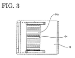
- a retainer insertion opening 14 is open preferably in one surface of a surrounding wall of the housing main body 12, and a hollow portion 14a extends in a direction intersecting with the longitudinal direction of the cavities 13 so as to substantially communicate with the cavities 13.
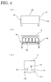
- the retainer 15 is, as shown in FIGS. 4(A) to 4(C), formed of a lattice-shaped frame provided with terminal insertion paths 15g substantially corresponding to the respective cavities 13 of the housing main body 12, and is at least partly inserted into the hollow portion 14a through the retainer insertion opening 14 of the housing main body 12.
- the retainer 15 can be locked in three positions having different depths of insertions: a first partial locking position P1 (see FIG. 5), a second partial locking position P2 (see FIG. 6) and a full locking position P3 (see FIG. 7) which is a completely inserted position.
- a pushing surface 15a as a pushing portion of the retainer 15 preferably is substantially in flush with the outer surface of the housing main body 12.
- the retainer 15 is held in the first partial locking position P1 in the housing main by a first locking means A comprised of locking projections 15b projecting from the opposite side walls of the retainer 15 and locking holes 12c formed in the side walls of the housing main body 12 corresponding to the opposite sides of the hollow portion 14a and engageable with the locking projections 15b.
- a first locking means A comprised of locking projections 15b projecting from the opposite side walls of the retainer 15 and locking holes 12c formed in the side walls of the housing main body 12 corresponding to the opposite sides of the hollow portion 14a and engageable with the locking projections 15b.
- escape holes 12d In side walls of the housing main body 12 are formed escape holes 12d for avoiding the interference with the locking projections 15b when the retainer 15 is inserted to the second partial locking position P2 or the full locking position P3, thereby removing a restriction on the movement of the retainer 15 in these positions.
- the upper and lower surfaces of the locking projections 15b are preferably slanted.
- the retainer 15 is held in the second partial locking position P2 and the full locking position P3 in the housing main body 12 by a second locking means B, which is comprised of a partial locking projection 12e and a full locking projection 12f projecting at different depths on the inner front and rear wall surfaces of the hollow portion 14a, and a partial locking claw 15c1 and a full locking claw 15d1 which project from the leading ends of flexible arms 15c, 15d extending in an inserting direction at the front and back positions of the opposite side walls of the retainer 15 and are to substantially face the locking projections 12e, 12f.
- a second locking means B which is comprised of a partial locking projection 12e and a full locking projection 12f projecting at different depths on the inner front and rear wall surfaces of the hollow portion 14a, and a partial locking claw 15c1 and a full locking claw 15d1 which project from the leading ends of flexible arms 15c, 15d extending in an inserting direction at the front and back positions of the opposite side walls of the retainer 15 and are to substantially
- the partial and full locking projections 12e, 12f preferably have a flat lower surface and a slanted upper surface or surfaces coming mutually into contact with each other, whereas the partial and full locking claws 15c1, 15d1 preferably have a slanted lower surface and a flat upper surface or surfaces coming mutually into contact with each other.
- the flat surface of the partial locking claw 15c1 is or can be engaged with the flat surface of the partial locking projection 12e in the second partial locking position P2 to restrict the movement of the retainer 15 in its withdrawing direction. Further, as shown in FIGS.
- the slanted surface of the partial locking claw 15c1 of the second locking means B comes into contact with the slanted surface of the partial locking projection 12e (FIG. 5), thereby creating a holding force acting in a direction to prevent the retainer 15 from moving in its inserting direction.
- the holding force of the retainer 15 in the first partial locking position P1 is larger than the one in the second partial locking position P2.
- the slanted surface of the full locking claw 15d1 of the second locking means B may come into contact with the slanted surface of an additional projection (not shown) provided on the housing main body 12 in the hollow portion 14a in a position before the full locking projection 12f when seen in the insertion direction of the retainer 15, thereby creating a holding force acting in a direction to prevent the retainer 15 from moving in its inserting direction.
- the holding force of the retainer 15 in the first partial locking position may be increased by, e.g. increasing the projecting height of the locking projections 15b of the first locking means A or flattening the inclination of the slanted upper surfaces thereof.
- the holding force acting between the housing main body 12 and the retainer 15 to hold the retainer 15 in the first partial locking position P1 is set at such a strength (60 to 75N) that the retainer 15 is not inadvertently pushed to the second partial locking position P2 e.g. by collision of an other connector housing or an other external matter with this connector housing 11 in particular during transportation of the connector housings 11.
- the holding force for the retainer 15 in the second partial locking position P2 is set at such a strength (15 to 30 N) that the retainer 5 can be easily pushed to the full locking position P3 by hands.
- the retainer 15 is mechanically at least partly inserted into the hollow portion 14a through the retainer insertion opening 14 to be held in the first partial locking position P1 as shown in FIGS. 5(A) and 5(B).
- the connector housings 11 are packed in a box to be transported to a location of a wiring harness assembling process.
- the partial locking claw 15c1 comes into contact with the partial locking projection 12e to restrict the movement of the retainer 15 in the inserting direction by a strong holding force.
- the connector housing 11 in which the retainer 15 is held in the first partial locking position P1 by a strong holding force as described above can be suitably supplied to a production process including an automatic assembling operation of assembling a subassembly by automatically inserting terminal fittings T connected with ends of wires.
- a production process including an automatic assembling operation of assembling a subassembly by automatically inserting terminal fittings T connected with ends of wires.
- the retainer 15 is or can be mechanically pushed from the first partial locking position P1 to the second partial locking position P2 by being pushed by a pushing portion M3 of the holder M1.
- a pushing stroke is set at a distance between the first and second partial locking positions P1 and P2 so as to prevent the retainer 15 from being pushed straight to the full locking position P3.
- the flexible arm 15c is so deformed that the partial locking claw 15c1 moves over the partial locking projection 12 to reach the second partial locking position and the flexible arm 15d comes into contact with the full locking projection 12f as shown in FIGS. 6(A) and 6(B) substantially to restrictively position the retainer 15.
- the terminal fittings T are inserted into the corresponding cavities 13 of the connector housing 11 set at the specified position by the holder M1 by the automatic assembling apparatus (not shown) to form a subassembly.
- the subassembly formed by the automatic assembling apparatus is arranged on a harness assembling table by hands and is bundled together with a subassembly formed in an other process.
- the terminal fittings T mounted on ends of wires of the other subassembly are inserted by hands. Since an operation of inserting the other terminal fittings T by hands is often performed after the terminal fittings T are inserted into the connector housings 11 by the automatic assembling apparatus in the assembling process of an automotive wiring harness, the retainer 15 needs to be held in the second partial locking position P2. After all the necessary terminal fittings T are inserted, the retainer 15 is pushed to the full locking position by hands.
- the retainer 15 can be lightly pushed from the second partial locking position P2 to the full locking position P3 with the terminal fittings T accommodated in the cavities 13.
- the flexible arm 15d is deformed to cause the full locking claw 15d1 to move over the full locking projection 12f, thereby effecting full locking.
- first locking means A is set in a separate position as the locking means for the retainer 15 in the first partial locking position P1 in the foregoing embodiment, it may be constructed by providing a projection substantially in the same position as the second partial locking means B, i.e. in a position where the partial locking projection 12e and the full locking projection 12f are formed.
- the holding force for partially locking the retainer in the housing main body is set larger in the first partial locking position than in the second partial locking position before the full locking position. This securely prevents the retainer from inadvertently moving to the full locking position by collision of an other connector housing or an other external matter with this connector housing during the transportation of the connector housings. Therefore, a cumbersome operation of pulling the retainer inadvertently pushed to the full locking portion back to the partial locking position needs not be performed in the wiring harness assembling process.
Landscapes
- Connector Housings Or Holding Contact Members (AREA)
Abstract
Description
- 11
- connector housing
- 12
- housing main body
- 12c
- locking hole
- 12d
- escape hole
- 12e
- partial locking projection
- 12f
- full locking projection
- 13
- cavity
- 14a
- hollow portion
- 15
- retainer
- 15b
- locking projection
- 15c1
- partial locking claw
- 15d1
- full locking claw
- T
- terminal fitting
- P1
- first partial locking position
- P2
- second partial locking position
- P3
- full locking position
- A
- first locking means
- B
- second locking means
Claims (9)
- A connector housing (11), comprising:one or more cavities (13) for at least partly accommodating terminal fittings (T),a housing main body (12) having a hollow portion (14a) extending in a direction intersecting with the longitudinal direction of the cavities (13), anda retainer (15) which can be locked in a partial locking position (P1, P2) where the retainer (15) is located at a shallow insertion position in the hollow portion (14a) and permits the insertion and/or withdrawal of the terminal fittings (T), and in a full locking position (P3) where the retainer (15) is located at a deeper insertion position in the hollow portion (14a) than in the partial locking position (P1, P2) to substantially lock the terminal fittings (T) so as not to come out of the cavities (13),wherein the partial locking position (P1, P2) of the retainer (15) comprises at least first and second partial locking positions (P1, P2) having different depths in the hollow portion (14a) in an inserting direction, and a holding force for partially locking the retainer (15) in the housing main body (12) is larger in the first partial locking position (P1) than in the second partial locking position (P2) located before the full locking position (P3).
- A connector housing according to claim 1, wherein the terminal fittings (T) are to be inserted through a rear end surface of the connector housing (11).
- A connector housing according to one or more of the preceding claims, wherein the hollow portion (14a) extends from a surrounding wall of the housing main body (12).
- A connector housing according to one or more of the preceding claims, wherein the retainer (15) is or can be locked in the first partial locking position (P1) in the housing main body (12) by a first locking means (A) comprising one or more mutually engageable locking projections (15b) and locking holes (12c) preferably formed on at least one side wall of the retainer (15) and a corresponding wall of the hollow portion (14a) .
- A connector housing according to one or more of the preceding claims, wherein the retainer (15) is or can be locked in the second partial locking position (P2) and the full locking position (P3) in the housing main body (12) by a second locking means (B) comprising one or more full and partial locking projections (12e, 12f) projecting from front and rear inner walls of the hollow portion (14a) in the housing main body (12) and corresponding full and partial locking claws (15c1, 15d1) projecting from the retainer (15) and selectively engageable with the full and partial locking projections (12e, 12f) in the full locking position (P3) and the second locking position (P2).
- A connector housing according to claim 4 and 5, wherein, when the retainer (15) is locked in the first partial locking position (P1) in the housing main body (12) by the first locking means (A), the partial locking claw (15c1) of the retainer (15) comes substantially into contact with the partial locking projection (12e) of the housing main body (12) to additionally create a supplemental holding force for preventing the movement of the retainer (15) in its inserting direction.
- A connector housing according to claim 4, 5 or 6, wherein the first locking means (A) removes a restriction on the movement of the retainer (15) when the retainer (15) is inserted to the second partial locking position (P2).
- A connector housing according to one or more of the preceding claims 4 to 7, wherein, when the retainer (15) is locked in the first partial locking position (P1) in the housing main body (12) by the first locking means (A), the full locking claw (15d1) of the retainer (15) comes substantially into contact with an additional projection of the housing main body (12) to additionally create a supplemental holding force for preventing the movement of the retainer (15) in its inserting direction.
- A connector housing according to one or more of the preceding claims, wherein the holding force acting between the housing main body (12) and the retainer (15) to hold the retainer (15) in the first partial locking position (P1) is set at a strength between about 50 and about 85 N, preferably between about 60 and about 75 N, while the holding force for the retainer (15) in the second partial locking position (P2) is preferably set at a strength between about 15 and about 30 N.
Applications Claiming Priority (2)
| Application Number | Priority Date | Filing Date | Title |
|---|---|---|---|
| JP2000153786 | 2000-05-24 | ||
| JP2000153786A JP3666358B2 (en) | 2000-05-24 | 2000-05-24 | Connector housing |
Publications (3)
| Publication Number | Publication Date |
|---|---|
| EP1158621A2 true EP1158621A2 (en) | 2001-11-28 |
| EP1158621A3 EP1158621A3 (en) | 2002-09-11 |
| EP1158621B1 EP1158621B1 (en) | 2005-03-02 |
Family
ID=18658978
Family Applications (1)
| Application Number | Title | Priority Date | Filing Date |
|---|---|---|---|
| EP01109960A Expired - Lifetime EP1158621B1 (en) | 2000-05-24 | 2001-04-24 | A connector housing |
Country Status (4)
| Country | Link |
|---|---|
| US (1) | US6390859B2 (en) |
| EP (1) | EP1158621B1 (en) |
| JP (1) | JP3666358B2 (en) |
| DE (1) | DE60109086T2 (en) |
Cited By (3)
| Publication number | Priority date | Publication date | Assignee | Title |
|---|---|---|---|---|
| WO2006106119A1 (en) * | 2005-04-05 | 2006-10-12 | Jst France Sas | Edge connector assembly with double locking |
| EP1732173A3 (en) * | 2005-06-10 | 2008-04-09 | Tyco Electronics AMP K.K. | Electrical connector |
| CN110176684A (en) * | 2018-02-19 | 2019-08-27 | 日本压着端子制造株式会社 | Connector assembly |
Families Citing this family (26)
| Publication number | Priority date | Publication date | Assignee | Title |
|---|---|---|---|---|
| JP3755431B2 (en) * | 2001-06-22 | 2006-03-15 | 住友電装株式会社 | connector |
| JP3806924B2 (en) * | 2001-11-22 | 2006-08-09 | 住友電装株式会社 | connector |
| JP3948524B2 (en) * | 2003-03-20 | 2007-07-25 | 矢崎総業株式会社 | connector |
| JP3872054B2 (en) | 2003-10-16 | 2007-01-24 | タイコエレクトロニクスアンプ株式会社 | Electrical connector |
| US7347742B2 (en) * | 2005-09-02 | 2008-03-25 | Tyco Electronics Corporation | Connector assembly including provision for body clip |
| JP4752655B2 (en) * | 2006-07-19 | 2011-08-17 | 住友電装株式会社 | connector |
| DE102007004065B4 (en) * | 2007-01-26 | 2010-01-28 | Tyco Electronics Amp Gmbh | plug |
| JP5181843B2 (en) * | 2008-06-03 | 2013-04-10 | 住友電装株式会社 | connector |
| JP4770967B2 (en) * | 2009-05-21 | 2011-09-14 | 住友電装株式会社 | connector |
| JP5707252B2 (en) * | 2011-06-24 | 2015-04-22 | 矢崎総業株式会社 | connector |
| JP5739757B2 (en) | 2011-07-19 | 2015-06-24 | 矢崎総業株式会社 | connector |
| JP5788745B2 (en) * | 2011-09-06 | 2015-10-07 | 矢崎総業株式会社 | connector |
| JP5751205B2 (en) * | 2012-04-11 | 2015-07-22 | 住友電装株式会社 | connector |
| US9484660B2 (en) * | 2014-11-13 | 2016-11-01 | Tyco Electronics Corporation | Electrical connector |
| US10109955B2 (en) | 2016-01-14 | 2018-10-23 | J.S.T. Corporation | Electrical connector apparatus having a male housing and a female housing with ribs |
| US10673169B2 (en) * | 2016-01-14 | 2020-06-02 | J.S.T. Corporation | Method of operating MSL connector series |
| US10622746B2 (en) * | 2016-01-15 | 2020-04-14 | J.S.T. Corporation | Terminal position assurance member and method of operating a terminal position assurance member |
| JP6610949B2 (en) | 2016-02-11 | 2019-11-27 | 株式会社オートネットワーク技術研究所 | Terminal fittings and connectors |
| JP6389847B2 (en) * | 2016-07-29 | 2018-09-12 | 矢崎総業株式会社 | connector |
| KR102375241B1 (en) * | 2017-08-30 | 2022-03-16 | 한국단자공업 주식회사 | Terminal position assurance and connector having the same |
| EP3679632B1 (en) * | 2017-09-07 | 2022-11-02 | Hirschmann Automotive GmbH | Plug connector with secondary lock for securing contact partners in the contact support of the plug connector |
| US10276966B1 (en) * | 2017-12-04 | 2019-04-30 | Te Connectivity Corporation | Electrical connector with alignment plate and seal |
| JP7480716B2 (en) * | 2021-01-21 | 2024-05-10 | 住友電装株式会社 | connector |
| CN113571940B (en) * | 2021-04-30 | 2023-08-11 | 安波福连接器系统(南通)有限公司 | Terminal position holder, connector and connector assembly |
| DE102021127030B3 (en) * | 2021-10-19 | 2022-12-22 | Md Elektronik Gmbh | connector |
| WO2026036066A1 (en) * | 2024-08-09 | 2026-02-12 | J.S.T. Corporation | Electrical connectors and systems thereof including terminal position assurance member |
Family Cites Families (12)
| Publication number | Priority date | Publication date | Assignee | Title |
|---|---|---|---|---|
| JP2700063B2 (en) * | 1989-06-27 | 1998-01-19 | 矢崎総業株式会社 | Electrical connector |
| JP2594373Y2 (en) * | 1993-01-14 | 1999-04-26 | 住友電装株式会社 | connector |
| JP2581476Y2 (en) * | 1993-04-13 | 1998-09-21 | 住友電装株式会社 | connector |
| JP2797923B2 (en) * | 1993-09-20 | 1998-09-17 | 住友電装株式会社 | connector |
| JP3093948B2 (en) * | 1995-02-22 | 2000-10-03 | 矢崎総業株式会社 | connector |
| JP3296707B2 (en) * | 1995-12-22 | 2002-07-02 | 古河電気工業株式会社 | Connector with terminal stopper |
| JP3120725B2 (en) * | 1996-03-13 | 2000-12-25 | 住友電装株式会社 | Connector with retainer |
| JPH09320672A (en) * | 1996-05-29 | 1997-12-12 | Yazaki Corp | connector |
| JP3171112B2 (en) * | 1996-06-26 | 2001-05-28 | 住友電装株式会社 | Retainer |
| JP3235479B2 (en) | 1996-07-30 | 2001-12-04 | 住友電装株式会社 | connector |
| JP3405440B2 (en) * | 1997-08-22 | 2003-05-12 | 住友電装株式会社 | Connector with retainer |
| US5997364A (en) * | 1998-01-09 | 1999-12-07 | Sumitomo Wiring Systems, Ltd. | Electrical connector |
-
2000
- 2000-05-24 JP JP2000153786A patent/JP3666358B2/en not_active Expired - Fee Related
-
2001
- 2001-04-24 DE DE60109086T patent/DE60109086T2/en not_active Expired - Fee Related
- 2001-04-24 EP EP01109960A patent/EP1158621B1/en not_active Expired - Lifetime
- 2001-04-30 US US09/845,444 patent/US6390859B2/en not_active Expired - Fee Related
Cited By (3)
| Publication number | Priority date | Publication date | Assignee | Title |
|---|---|---|---|---|
| WO2006106119A1 (en) * | 2005-04-05 | 2006-10-12 | Jst France Sas | Edge connector assembly with double locking |
| EP1732173A3 (en) * | 2005-06-10 | 2008-04-09 | Tyco Electronics AMP K.K. | Electrical connector |
| CN110176684A (en) * | 2018-02-19 | 2019-08-27 | 日本压着端子制造株式会社 | Connector assembly |
Also Published As
| Publication number | Publication date |
|---|---|
| DE60109086D1 (en) | 2005-04-07 |
| JP2001332335A (en) | 2001-11-30 |
| US6390859B2 (en) | 2002-05-21 |
| EP1158621A3 (en) | 2002-09-11 |
| EP1158621B1 (en) | 2005-03-02 |
| DE60109086T2 (en) | 2006-04-13 |
| US20010049235A1 (en) | 2001-12-06 |
| JP3666358B2 (en) | 2005-06-29 |
Similar Documents
| Publication | Publication Date | Title |
|---|---|---|
| EP1158621B1 (en) | A connector housing | |
| EP0344691B1 (en) | Double engagement structure for terminal and connector | |
| US6244880B1 (en) | Low-insertion force connector | |
| US6840789B2 (en) | Connector and a method of assembling it | |
| EP0975059A2 (en) | Connector provided with a retainer | |
| EP1054481A1 (en) | A connector | |
| EP1863135A2 (en) | A connector and an unlocking jig therefor | |
| EP1100156B1 (en) | A connector and a connector assembly | |
| US6482035B2 (en) | Press-connecting connector | |
| US6872093B2 (en) | Terminal fitting and a connector provided therewith | |
| EP1592091B1 (en) | An intermediate connector | |
| EP0905819B1 (en) | A connector provided with a retainer | |
| US20060281374A1 (en) | Electrical Connector | |
| JPH09245869A (en) | Connector with terminal lock | |
| EP1601063B1 (en) | A connector device | |
| JP4544065B2 (en) | connector | |
| US6488547B2 (en) | Connector with longitudinally spaced locks for retaining terminal fittings | |
| EP1150388B1 (en) | A shake preventing construction for a terminal fitting and connector | |
| US7125292B2 (en) | Connector with retainer having means for preventing inclination of the front part | |
| JPH1050386A (en) | connector | |
| JPH1050382A (en) | connector | |
| JP2004119088A (en) | Electric connector | |
| US7001224B2 (en) | Connector with retainer for locking terminal fitings | |
| JP2020198277A (en) | Electrical connector and locking method of connection terminal in electrical connector | |
| JPH11162548A (en) | connector |
Legal Events
| Date | Code | Title | Description |
|---|---|---|---|
| PUAI | Public reference made under article 153(3) epc to a published international application that has entered the european phase |
Free format text: ORIGINAL CODE: 0009012 |
|
| 17P | Request for examination filed |
Effective date: 20010517 |
|
| AK | Designated contracting states |
Kind code of ref document: A2 Designated state(s): AT BE CH CY DE DK ES FI FR GB GR IE IT LI LU MC NL PT SE TR |
|
| AX | Request for extension of the european patent |
Free format text: AL;LT;LV;MK;RO;SI |
|
| PUAL | Search report despatched |
Free format text: ORIGINAL CODE: 0009013 |
|
| AK | Designated contracting states |
Kind code of ref document: A3 Designated state(s): AT BE CH CY DE DK ES FI FR GB GR IE IT LI LU MC NL PT SE TR |
|
| AX | Request for extension of the european patent |
Free format text: AL;LT;LV;MK;RO;SI |
|
| AKX | Designation fees paid |
Designated state(s): DE GB |
|
| GRAP | Despatch of communication of intention to grant a patent |
Free format text: ORIGINAL CODE: EPIDOSNIGR1 |
|
| GRAS | Grant fee paid |
Free format text: ORIGINAL CODE: EPIDOSNIGR3 |
|
| GRAA | (expected) grant |
Free format text: ORIGINAL CODE: 0009210 |
|
| AK | Designated contracting states |
Kind code of ref document: B1 Designated state(s): DE GB |
|
| REG | Reference to a national code |
Ref country code: GB Ref legal event code: FG4D |
|
| REG | Reference to a national code |
Ref country code: IE Ref legal event code: FG4D |
|
| REF | Corresponds to: |
Ref document number: 60109086 Country of ref document: DE Date of ref document: 20050407 Kind code of ref document: P |
|
| PLBE | No opposition filed within time limit |
Free format text: ORIGINAL CODE: 0009261 |
|
| STAA | Information on the status of an ep patent application or granted ep patent |
Free format text: STATUS: NO OPPOSITION FILED WITHIN TIME LIMIT |
|
| 26N | No opposition filed |
Effective date: 20051205 |
|
| PGFP | Annual fee paid to national office [announced via postgrant information from national office to epo] |
Ref country code: GB Payment date: 20070418 Year of fee payment: 7 |
|
| PGFP | Annual fee paid to national office [announced via postgrant information from national office to epo] |
Ref country code: DE Payment date: 20080502 Year of fee payment: 8 |
|
| GBPC | Gb: european patent ceased through non-payment of renewal fee |
Effective date: 20080424 |
|
| PG25 | Lapsed in a contracting state [announced via postgrant information from national office to epo] |
Ref country code: GB Free format text: LAPSE BECAUSE OF NON-PAYMENT OF DUE FEES Effective date: 20080424 |
|
| PG25 | Lapsed in a contracting state [announced via postgrant information from national office to epo] |
Ref country code: DE Free format text: LAPSE BECAUSE OF NON-PAYMENT OF DUE FEES Effective date: 20091103 |