EP1158573A1 - Method and apparatus for forming interconnection - Google Patents
Method and apparatus for forming interconnection Download PDFInfo
- Publication number
- EP1158573A1 EP1158573A1 EP00966463A EP00966463A EP1158573A1 EP 1158573 A1 EP1158573 A1 EP 1158573A1 EP 00966463 A EP00966463 A EP 00966463A EP 00966463 A EP00966463 A EP 00966463A EP 1158573 A1 EP1158573 A1 EP 1158573A1
- Authority
- EP
- European Patent Office
- Prior art keywords
- substrate
- ultrafine
- dispersed liquid
- metal
- heating
- Prior art date
- Legal status (The legal status is an assumption and is not a legal conclusion. Google has not performed a legal analysis and makes no representation as to the accuracy of the status listed.)
- Withdrawn
Links
Images



Classifications
-
- H—ELECTRICITY
- H05—ELECTRIC TECHNIQUES NOT OTHERWISE PROVIDED FOR
- H05K—PRINTED CIRCUITS; CASINGS OR CONSTRUCTIONAL DETAILS OF ELECTRIC APPARATUS; MANUFACTURE OF ASSEMBLAGES OF ELECTRICAL COMPONENTS
- H05K3/00—Apparatus or processes for manufacturing printed circuits
- H05K3/40—Forming printed elements for providing electric connections to or between printed circuits
- H05K3/4038—Through-connections; Vertical interconnect access [VIA] connections
- H05K3/4053—Through-connections; Vertical interconnect access [VIA] connections by thick-film techniques
- H05K3/4061—Through-connections; Vertical interconnect access [VIA] connections by thick-film techniques for via connections in inorganic insulating substrates
-
- B—PERFORMING OPERATIONS; TRANSPORTING
- B05—SPRAYING OR ATOMISING IN GENERAL; APPLYING FLUENT MATERIALS TO SURFACES, IN GENERAL
- B05C—APPARATUS FOR APPLYING FLUENT MATERIALS TO SURFACES, IN GENERAL
- B05C11/00—Component parts, details or accessories not specifically provided for in groups B05C1/00 - B05C9/00
- B05C11/02—Apparatus for spreading or distributing liquids or other fluent materials already applied to a surface ; Controlling means therefor; Control of the thickness of a coating by spreading or distributing liquids or other fluent materials already applied to the coated surface
- B05C11/08—Spreading liquid or other fluent material by manipulating the work, e.g. tilting
-
- C—CHEMISTRY; METALLURGY
- C23—COATING METALLIC MATERIAL; COATING MATERIAL WITH METALLIC MATERIAL; CHEMICAL SURFACE TREATMENT; DIFFUSION TREATMENT OF METALLIC MATERIAL; COATING BY VACUUM EVAPORATION, BY SPUTTERING, BY ION IMPLANTATION OR BY CHEMICAL VAPOUR DEPOSITION, IN GENERAL; INHIBITING CORROSION OF METALLIC MATERIAL OR INCRUSTATION IN GENERAL
- C23C—COATING METALLIC MATERIAL; COATING MATERIAL WITH METALLIC MATERIAL; SURFACE TREATMENT OF METALLIC MATERIAL BY DIFFUSION INTO THE SURFACE, BY CHEMICAL CONVERSION OR SUBSTITUTION; COATING BY VACUUM EVAPORATION, BY SPUTTERING, BY ION IMPLANTATION OR BY CHEMICAL VAPOUR DEPOSITION, IN GENERAL
- C23C18/00—Chemical coating by decomposition of either liquid compounds or solutions of the coating forming compounds, without leaving reaction products of surface material in the coating; Contact plating
- C23C18/02—Chemical coating by decomposition of either liquid compounds or solutions of the coating forming compounds, without leaving reaction products of surface material in the coating; Contact plating by thermal decomposition
-
- C—CHEMISTRY; METALLURGY
- C23—COATING METALLIC MATERIAL; COATING MATERIAL WITH METALLIC MATERIAL; CHEMICAL SURFACE TREATMENT; DIFFUSION TREATMENT OF METALLIC MATERIAL; COATING BY VACUUM EVAPORATION, BY SPUTTERING, BY ION IMPLANTATION OR BY CHEMICAL VAPOUR DEPOSITION, IN GENERAL; INHIBITING CORROSION OF METALLIC MATERIAL OR INCRUSTATION IN GENERAL
- C23C—COATING METALLIC MATERIAL; COATING MATERIAL WITH METALLIC MATERIAL; SURFACE TREATMENT OF METALLIC MATERIAL BY DIFFUSION INTO THE SURFACE, BY CHEMICAL CONVERSION OR SUBSTITUTION; COATING BY VACUUM EVAPORATION, BY SPUTTERING, BY ION IMPLANTATION OR BY CHEMICAL VAPOUR DEPOSITION, IN GENERAL
- C23C18/00—Chemical coating by decomposition of either liquid compounds or solutions of the coating forming compounds, without leaving reaction products of surface material in the coating; Contact plating
- C23C18/02—Chemical coating by decomposition of either liquid compounds or solutions of the coating forming compounds, without leaving reaction products of surface material in the coating; Contact plating by thermal decomposition
- C23C18/08—Chemical coating by decomposition of either liquid compounds or solutions of the coating forming compounds, without leaving reaction products of surface material in the coating; Contact plating by thermal decomposition characterised by the deposition of metallic material
-
- H—ELECTRICITY
- H10—SEMICONDUCTOR DEVICES; ELECTRIC SOLID-STATE DEVICES NOT OTHERWISE PROVIDED FOR
- H10P—GENERIC PROCESSES OR APPARATUS FOR THE MANUFACTURE OR TREATMENT OF DEVICES COVERED BY CLASS H10
- H10P14/00—Formation of materials, e.g. in the shape of layers or pillars
- H10P14/40—Formation of materials, e.g. in the shape of layers or pillars of conductive or resistive materials
- H10P14/46—Formation of materials, e.g. in the shape of layers or pillars of conductive or resistive materials using a liquid
-
- H—ELECTRICITY
- H10—SEMICONDUCTOR DEVICES; ELECTRIC SOLID-STATE DEVICES NOT OTHERWISE PROVIDED FOR
- H10P—GENERIC PROCESSES OR APPARATUS FOR THE MANUFACTURE OR TREATMENT OF DEVICES COVERED BY CLASS H10
- H10P72/00—Handling or holding of wafers, substrates or devices during manufacture or treatment thereof
- H10P72/04—Apparatus for manufacture or treatment
- H10P72/0402—Apparatus for fluid treatment
-
- H—ELECTRICITY
- H10—SEMICONDUCTOR DEVICES; ELECTRIC SOLID-STATE DEVICES NOT OTHERWISE PROVIDED FOR
- H10P—GENERIC PROCESSES OR APPARATUS FOR THE MANUFACTURE OR TREATMENT OF DEVICES COVERED BY CLASS H10
- H10P72/00—Handling or holding of wafers, substrates or devices during manufacture or treatment thereof
- H10P72/04—Apparatus for manufacture or treatment
- H10P72/0448—Apparatus for applying a liquid, a resin, an ink or the like
-
- H—ELECTRICITY
- H10—SEMICONDUCTOR DEVICES; ELECTRIC SOLID-STATE DEVICES NOT OTHERWISE PROVIDED FOR
- H10W—GENERIC PACKAGES, INTERCONNECTIONS, CONNECTORS OR OTHER CONSTRUCTIONAL DETAILS OF DEVICES COVERED BY CLASS H10
- H10W20/00—Interconnections in chips, wafers or substrates
- H10W20/01—Manufacture or treatment
- H10W20/031—Manufacture or treatment of conductive parts of the interconnections
- H10W20/056—Manufacture or treatment of conductive parts of the interconnections by filling conductive material into holes, grooves or trenches
-
- H—ELECTRICITY
- H10—SEMICONDUCTOR DEVICES; ELECTRIC SOLID-STATE DEVICES NOT OTHERWISE PROVIDED FOR
- H10W—GENERIC PACKAGES, INTERCONNECTIONS, CONNECTORS OR OTHER CONSTRUCTIONAL DETAILS OF DEVICES COVERED BY CLASS H10
- H10W20/00—Interconnections in chips, wafers or substrates
- H10W20/40—Interconnections external to wafers or substrates, e.g. back-end-of-line [BEOL] metallisations or vias connecting to gate electrodes
- H10W20/41—Interconnections external to wafers or substrates, e.g. back-end-of-line [BEOL] metallisations or vias connecting to gate electrodes characterised by their conductive parts
- H10W20/425—Barrier, adhesion or liner layers
-
- H—ELECTRICITY
- H05—ELECTRIC TECHNIQUES NOT OTHERWISE PROVIDED FOR
- H05K—PRINTED CIRCUITS; CASINGS OR CONSTRUCTIONAL DETAILS OF ELECTRIC APPARATUS; MANUFACTURE OF ASSEMBLAGES OF ELECTRICAL COMPONENTS
- H05K1/00—Printed circuits
- H05K1/02—Details
- H05K1/03—Use of materials for the substrate
- H05K1/0306—Inorganic insulating substrates, e.g. ceramic, glass
-
- H—ELECTRICITY
- H05—ELECTRIC TECHNIQUES NOT OTHERWISE PROVIDED FOR
- H05K—PRINTED CIRCUITS; CASINGS OR CONSTRUCTIONAL DETAILS OF ELECTRIC APPARATUS; MANUFACTURE OF ASSEMBLAGES OF ELECTRICAL COMPONENTS
- H05K2201/00—Indexing scheme relating to printed circuits covered by H05K1/00
- H05K2201/02—Fillers; Particles; Fibers; Reinforcement materials
- H05K2201/0203—Fillers and particles
- H05K2201/0242—Shape of an individual particle
- H05K2201/0257—Nanoparticles
-
- H—ELECTRICITY
- H05—ELECTRIC TECHNIQUES NOT OTHERWISE PROVIDED FOR
- H05K—PRINTED CIRCUITS; CASINGS OR CONSTRUCTIONAL DETAILS OF ELECTRIC APPARATUS; MANUFACTURE OF ASSEMBLAGES OF ELECTRICAL COMPONENTS
- H05K3/00—Apparatus or processes for manufacturing printed circuits
- H05K3/02—Apparatus or processes for manufacturing printed circuits in which the conductive material is applied to the surface of the insulating support and is thereafter removed from such areas of the surface which are not intended for current conducting or shielding
- H05K3/04—Apparatus or processes for manufacturing printed circuits in which the conductive material is applied to the surface of the insulating support and is thereafter removed from such areas of the surface which are not intended for current conducting or shielding the conductive material being removed mechanically, e.g. by punching
- H05K3/045—Apparatus or processes for manufacturing printed circuits in which the conductive material is applied to the surface of the insulating support and is thereafter removed from such areas of the surface which are not intended for current conducting or shielding the conductive material being removed mechanically, e.g. by punching by making a conductive layer having a relief pattern, followed by abrading of the raised portions
-
- H—ELECTRICITY
- H05—ELECTRIC TECHNIQUES NOT OTHERWISE PROVIDED FOR
- H05K—PRINTED CIRCUITS; CASINGS OR CONSTRUCTIONAL DETAILS OF ELECTRIC APPARATUS; MANUFACTURE OF ASSEMBLAGES OF ELECTRICAL COMPONENTS
- H05K3/00—Apparatus or processes for manufacturing printed circuits
- H05K3/10—Apparatus or processes for manufacturing printed circuits in which conductive material is applied to the insulating support in such a manner as to form the desired conductive pattern
- H05K3/102—Apparatus or processes for manufacturing printed circuits in which conductive material is applied to the insulating support in such a manner as to form the desired conductive pattern by bonding of conductive powder, i.e. metallic powder
Definitions
- the present invention relates to a method of and an apparatus for forming an interconnection, and more particularly to a method of and an apparatus for forming a fine interconnection in a highly integrated circuit formed on a semiconductor substrate such as a semiconductor wafer or the like.
- Aluminum or aluminum alloy has generally been used as a material for forming interconnection circuits on semiconductor substrates. It has been customary to grow a film of the material according to a process such as sputtering, CVD, or the like and then produce a pattern in the film according to etching or the like. As the level of circuit integration increases in recent years, there is a demand for the usage of silver, copper or its alloy, which has a higher conductivity, as an interconnection material. Since it is difficult to etch these materials, it has been proposed to immerse a substrate having interconnection pattern trenches therein in a plating liquid and perform electrolytic or electroless plating on the substrate to embed the trenches with silver, copper or its alloy.
- the electrolytic plating process is capable of growing a film only on an electrically conductive material, whereas the electroless plating process suffers a problem in that substances contained in the plating liquid affect the natural environment and the working environment. Accordingly, there has been a strong need for the development of a metal interconnection technology as a substitute for the plating processes.
- the present invention has been made in view of the foregoing problems and demand. It is an object of the present invention to provide a method of and an apparatus for forming an interconnection by stably depositing an interconnection metal of good quality as a substitute for the conventional plating processes.
- a method of forming an interconnection comprising the steps of preparing a substrate having fine recesses formed in a surface thereof, dispersing ultrafine particles made at least partly of a metal in a predetermined solvent, producing an ultrafine particle dispersed liquid, supplying the ultrafine particle dispersed liquid to the fine recesses of the substrate, heating the substrate to melt and bond the metal, and chemical mechanical polishing the surface of the substrate to remove an excessively attached metal therefrom.
- the ultrafine particle dispersed liquid may be placed in a container, providing a liquid reservoir, and the substrate may be immersed in the liquid reservoir to supply the ultrafine particle dispersed liquid to only the fine recesses of the substrate.
- the ultrafine particle dispersed liquid may be supplied to the fine recesses of the substrate by being coated or sprayed in the fine recesses of the substrate and/or on areas surrounding the fine recesses.
- the ultrafine particle dispersed liquid may be coated by a spin coating process.
- the method according to claim 1 comprises the step of evaporating the solvent between the step of supplying the ultrafine particle dispersed liquid to the fine recesses of the substrate and the step of heating the substrate to melt and bond the metal.
- each of the ultrafine particles comprises an ultrafine composite metal particle comprising a core made substantially of a metal component and a covering layer made of an organic substance chemically bonded to the core.
- ultrafine particles made at least partly of a metal there has been proposed a process of evaporating the metal in a vacuum in the presence of a small amount of a gas to agglomerate ultrafine particles made of only the metal from the gas phase, producing ultrafine metal particles.
- a physical process does not lend itself to mass production as the amount of generated ultrafine metal particles is small, and is costly because a device for generating an electron beam, a plasma, or a laser beam, etc. or a device for performing inductive heating is necessary to evaporate the metal.
- the particle diameters range in a wide distribution, some of the metal particles remain unmelted when heated, failing to obtain a uniform metal film of low resistance.
- ultrafine particles made of only the metal When ultrafine particles made of only the metal is used, the ultrafine particles tend to agglomerate in a dispersed liquid, the ultrafine particle dispersed liquid is liable to provide an irregular covering layer.
- One solution would be to add a suitable surface active agent to the ultrafine particle dispersed liquid to turn them into a protective colloid.
- a protective colloid fails to provide sufficient dispersion stability.
- the bonded structure of ultrafine composite metal particles according to the present invention appears to be such that a core made of a metal component and an organic compound making up a covering layer share metal molecules, or an organic compound and a core form a complex-analogous structure by way of an ionic bond, through the details of the bonded structure are not clear. Since such ultrafine composite metal particles can be produced by a chemical process in a liquid phase, they can be mass-produced at a reduced cost in an ordinary atmospheric environment with a simple apparatus without the need for a large vacuum device. Since the ultrafine composite metal particles have a uniform diameter, all the ultrafine composite metal particles are fused together at a constant temperature.
- the ultrafine composite metal particles are covered with an organic metal compound therearound, their ability to agglomerate in a solvent is small, and hence they can easily be scattered uniformly over the surface of the substrate.
- the ultrafine composite metal particles are stable and hence can easily be handled. Even after the solvent is evaporated, the ultrafine composite metal particles remain chemically stable until they are decomposed with heat and can be handled for easy process management.
- the ultrafine particles have an average diameter ranging from 1 to 20 nm.
- the melting point of a metal particle is lowered as the diameter thereof is reduced. This effect starts to manifest itself when the diameter of the metal particle is 20 nm or less, and becomes distinctive when the diameter of the metal particle is 10 nm or less. Therefore, the average diameter of the ultrafine particles are preferably in the range from 1 to 20 nm, and preferably in the range from 1 to 10 nm depending on the shape and dimensions of the fine recesses and the structure of the semiconductor device.
- the ultrafine particle dispersed liquid has a predetermined surface tension to increase adhesiveness of the ultrafine particle dispersed liquid to the fine recesses of the substrate and/or areas surrounding the fine recesses.
- the ultrafine particle dispersed liquid having a predetermined surface tension With the ultrafine particle dispersed liquid having a predetermined surface tension, the applicability of the ultrafine particle dispersed liquid in the fine recesses of the substrate and on areas surrounding the fine recesses is increased.
- the substrate with a large amount of liquid held thereon can be dried, so that a sufficient amount of ultrafine particles can be supplied to the recesses and the areas surrounding the fine recesses. Consequently, it is not necessary to repeat the applying and drying steps, and the fine recesses can be filled with the metal according to a simple process.
- the step of heating the ultrafine particles is carried out under the control of an atmosphere.
- an oil mist produced when the ultrafine particles are decomposed is removed from the substrate surface by a nitrogen gas, for example. Therefore, the oil mist is prevented from fuming and becoming stagnant on the substrate surface to contaminate the substrate.
- the step of heating the substrate is carried out in an inactive gas atmosphere containing a small amount of oxygen or ozone, and thereafter in a pure inactive gas atmosphere.
- the oxygen or ozone acts as a catalyst to separate the organic substance and the metal from each other, thus promoting the decomposition of the ultrafine particles.
- the ultrafine composite metal particle layer is heated (baked) while a nitrogen gas containing a small amount of oxygen or ozone is flowing, and thereafter a nitrogen gas containing hydrogen is supplied to reduce the silver to form interconnections of pure copper, after which the gas is changed to a nitrogen gas. In this manner, the interconnections can be formed efficiently.
- the step of heating the substrate is carried out at a temperature of 450°C or lower. In this manner, any thermal effect on the semiconductor substrate and circuits formed thereon can be reduced.
- an apparatus for forming an interconnection comprising a dispersed liquid supply device for supplying an ultrafine particle dispersed liquid produced by dispersing ultrafine particles made at least partly of a metal in a predetermined solvent, to a surface of a substrate having fine recesses formed therein; and a heat-treating device for heating the substrate to melt and bond the metal.
- the apparatus according to claim 10 further comprises a polishing device for chemical mechanical polishing the surface of the substrate to remove an excessively attached metal therefrom.
- the dispersed liquid supply device also evaporates the solvent in the ultrafine particle dispersed liquid supplied to the surface of the substrate.
- the apparatus according to any one of claims 10 through 12 further comprises a supplementary drying device for supplementarily drying the solvent in the ultrafine particle dispersed liquid supplied to the surface of the substrate.
- a supplementary drying device for supplementarily drying the solvent in the ultrafine particle dispersed liquid supplied to the surface of the substrate.
- the heat-treating device is arranged to heat the substrate under the control of an atmosphere.
- the heat-treating device has a heating plate which houses a heater for heating the substrate at a temperature of 450°C or lower and a cooling mechanism.
- the respective devices are sequentially arranged in an indoor facility along a direction in which the substrate moves. With this arrangement, corresponding steps can successively be performed by the devices in the sequence.
- the respective devices are accommodated individually in respective chambers disposed radially around a central transfer chamber with a transfer robot disposed therein. With this arrangement, corresponding steps can be individually performed and can be combined with each other.
- each of the ultrafine particles comprises an ultrafine composite metal particle comprising a core made substantially of a metal component and a covering layer made of an organic substance chemically bonded to the core.
- the ultrafine particles have an average diameter ranging from 1 to 20 nm.
- a dispersed liquid supply device for supplying an ultrafine particle dispersed liquid produced by dispersing ultrafine particles made at least partly of a metal in a predetermined solvent, to a surface of a substrate, comprising: a substrate holder for holding and rotating the substrate; a dispersed liquid supply nozzle for dropping the ultrafine particle dispersed liquid to the surface of the substrate held by the substrate holder at a central portion thereof or an area surrounding the central portion; a bevel washing nozzle for supplying a washing liquid to a bevel of the substrate held by the substrate holder; and a reverse side washing nozzle for supplying a gas or a washing liquid to the reverse side of the substrate held by the substrate holder.
- the ultrafine particle dispersed liquid is dropped onto the center of the surface of the substrate to uniformly coat the surface of the substrate with the ultrafine particle dispersed liquid.
- the bevel washing nozzle supplies the washing liquid to the bevel of the substrate to prevent the ultrafine particle dispersed liquid from dropping from the edge of the substrate and flowing across the edge of the substrate to the reverse side of the substrate.
- the reverse side washing nozzles also supplies the gas or the washing liquid to the reverse side of the substrate to prevent the reverse side of the substrate from being contaminated.
- a heat-treating device for heating ultrafine particles made at least partly of a metal to melt and bond the metal, comprising a heating plate for holding and heating the substrate, and a housing having a gas supply port and a gas discharge port and surrounding a space above the substrate held by the heating plate to form a gas chamber between the housing and the heating plate.
- the ultrafine particles are heated under the control of an atmosphere so that an oil mist produced when the ultrafine particles are decomposed is removed from the substrate surface, and prevented from fuming and becoming stagnant on the substrate surface to contaminate the substrate.
- the embodiment will be used as one type of a so-called dual-damascene process for forming interconnections of copper or silver layers in fine recesses such as interconnection trenches defined in the surface of a semiconductor substrate and vertical holes, referred to as contact holes, that interconnect layers.
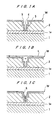
- FIGS. 1A through 1C show successive steps of a method of forming an interconnection according to the present invention.
- a semiconductor substrate W includes a semiconductor base 1 with a semiconductor device formed thereon, an electrically conductive layer 1a disposed on the semiconductor base 1, an insulating film 2 of SiO 2 deposited on the electrically conductive layer 1a and having a contact hole 3 and an interconnection trench 4 defined therein by lithography and etching, and a barrier layer 5 of TaN or the like deposited on the surface formed so far.
- An ultrafine particle dispersed liquid L (see FIG. 1B) is prepared which comprises, as shown in FIGS. 2A and 2B, ultrafine composite metal particles 14 each comprising a core 10 substantially made of a metal component and a covering layer 12 made of an organic compound and dispersed in a given solvent.
- the ultrafine composite metal particles 14 are stable because their cores 10 are covered with the covering layers 12 of an organic compound, and have a small tendency to agglomerate in the solvent.
- the ratio of the metal component in the ultrafine composite metal particles 14 usually ranges from 50 to 90 weight %.
- the ratio of the metal component in the ultrafine composite metal particles 14 is usually in the range from 60 to 90 weight %, and preferably in the range from 70 to 90 weight %.
- Each of the ultrafine composite metal particles 14 is composed of an organic compound and a metal component derived from a metal salt as a starting material, e.g., carbonate, formate, or acetate.
- Each of the ultrafine composite metal particles 14 has its central region made of the metal component and surrounded by the ionic organic compound. At this time, the organic compound and the metal component are chemically bonded partly or wholly to each other, and exist in integral unity.
- the ultrafine composite metal particles 14 have high stability and are stable at a higher metal concentration unlike conventional ultrafine metal particles which are stabilized by being coated with a surface active agent.
- the cores 10 of the ultrafine composite metal particles 14 have an average diameter which usually ranges from 1 to 20 nm and preferably from 1 to 10 nm.
- the ultrafine composite metal particles 14 can be manufactured by heating a metal salt, e.g., carbonate, formate, or acetate, in a nonaqueous solvent in the presence of an ionic organic substance at a temperature that is equal to or higher than the decomposition reducing temperature of the metal salt and also is equal to or lower than the decomposition temperature of the ionic organic substance.
- a metal salt e.g., carbonate, formate, or acetate
- the metal component comprises at least one of Cu, Ag, Au, Zn, In, Si, Sn, Pd, Fe, Co, Ni, Ru, Rh, Os, Ir, Pt, Cr, Mo, Ba, Bi, Al, W, Ta, Ti, and Pb.
- the ionic organic substance comprises a fatty acid having a carbon number of 5 or more, an alkylbenzene sulfonic acid, or an alkyl sulfonic acid.
- the heating temperature is equal to or higher than the decomposition reducing temperature of the metal salt, e.g., carbonate, formate, or acetate, and also is equal to or lower than the decomposition temperature of the ionic organic substance.
- the metal salt e.g., carbonate, formate, or acetate
- the metal salt since its decomposition starting temperature is 200°C, the metal salt may be kept at a temperature that is equal to or higher than 200°C and low enough to keep the ionic organic substance from being decomposed.
- the heating atmosphere should preferably be an inactive gas atmosphere.
- the metal salt may be heated in the atmosphere by selecting a nonaqueous solvent.
- alcohols may be added for accelerating the reaction.
- Such alcohols are not limited to any particular alcohols, but may be lauryl alcohol, glycerin, ethylene alcohol, or the like, for example, insofar as they can accelerate the reaction.
- the amount of the added alcohol may be determined depending on the type of the added alcohol. Usually, the alcohol is added in 5 through 20 parts by weight, preferably 5 through 10 parts by weight, with respect to 100 parts by weight of the metal salt.
- the ultrafine composite metal particles 14 are refined according to a known refining process.
- the refining process includes a centrifugal separation process, a film refining process, a solvent extracting process, or the like, for example.
- the ultrafine composite metal particles 14 thus produced are dispersed in a suitable solvent, producing the ultrafine particle dispersed liquid L. Since the ultrafine composite metal particles 14 as dispersed particles are very small, the ultrafine particle dispersed liquid L is substantially transparent when the ultrafine composite metal particles 14 are mixed and stirred. Properties of the ultrafine particle dispersed liquid L such as surface tension, viscosity, etc. may be adjusted by appropriately selecting the type of the solvent, the concentration of the ultrafine composite metal particles and temperature, etc.
- the ultrafine particle dispersed liquid L is dropped onto the substrate W at its center or a spot slightly off the center according to a spin coating process, i.e., while the substrate W is being rotated, for example.
- a spin coating process i.e., while the substrate W is being rotated, for example.
- the dropping of the ultrafine particle dispersed liquid L is stopped, thus uniformly coating the entire interconnection forming surface of the substrate W, as shown in FIG. 1B.
- a liquid film having a given thickness that is determined by the viscosity of the ultrafine particle dispersed liquid L and the surface tension acting between the substrate surface and the ultrafine particle dispersed liquid L is formed on the substrate surface.
- the substrate W is rotated in a spin drying process (air drying process) to evaporate the solvent in the ultrafine particle dispersed liquid L, thus forming an ultrafine composite metal particle layer 6, which comprises an agglomeration of ultrafine composite metal particles as a solid material, in the small recesses (the contact hole 3 and the interconnection trench 4) and on the substrate surface, as shown in FIG. 1C.
- a spin drying process air drying process
- a liquid film having a given thickness may be formed on the interconnection forming surface of the substrate W by immersing the substrate W in the ultrafine particle dispersed liquid L according to a dipping process.
- undesired areas of the substrate W may be masked, and the ultrafine particle dispersed liquid L may be stirred, or the ultrafine particle dispersed liquid L or the substrate W may be vibrated in order to fill the small recesses (the contact hole 3 and the interconnection trench 4) with the ultrafine particle dispersed liquid L.
- the process of applying the ultrafine particle dispersed liquid L to the interconnection forming surface of the substrate W and spin-drying the substrate W is repeated a plurality of times as required.
- the immersing and drying process is put to an end when the small recesses (the contact hole 3 and the interconnection trench 4) are filled to a certain level with the ultrafine composite metal particle layer 6.
- the ultrafine composite metal particle layer 6 is decomposed with heat in a controlled atmosphere by a heating furnace to melt and bond the ultrafine composite metal particles together, thus forming a metal interconnection 7, as shown in FIG. 3B.
- the ultrafine composite metal particle layer 6 is heated to 300°C in 5 minutes, held at 300°C for 5 minutes, and thereafter cooled to the room temperature in 10 minutes.
- This heating process is first carried out in an inactive gas atmosphere of N 2 or the like containing a small amount of oxygen or ozone, and thereafter carried out in a pure inactive gas atmosphere of only N 2 or the like.
- the oxygen or ozone acts as a catalyst to separate the organic substance and the metal from each other, thus promoting the decomposition of the ultrafine particles.
- An oil mist produced when the ultrafine particles are decomposed is removed from the substrate surface by the N 2 gas, for example. Therefore, the oil mist is prevented from fuming and becoming stagnant on the substrate surface to contaminate the substrate.
- the ultrafine composite metal particle layer be heated (baked) while a nitrogen gas containing a small amount of oxygen or ozone is flowing, and thereafter a nitrogen gas containing hydrogen is supplied to prevent the silver from being oxidized and reduce the silver to form interconnections of pure silver, after which the gas is changed to a nitrogen gas. In this manner, the interconnections can be formed efficiently.
- any thermal effect on the semiconductor substrate and circuits formed thereon can be reduced.
- the substrate is chemically and mechanically polished to remove the metal and the barrier layer that have been attached to the substrate surface.
- An insulating layer may be formed over the metal interconnection 7, and a structure as shown in FIG. 1A may be formed again on the insulating layer, after which the above steps may be repeated to produce a multilayer interconnection structure.
- ultrafine composite metal particles are used as ultrafine particles, and dispersed in a solvent to produce an ultrafine particle dispersed liquid.
- the ultrafine composite metal particles may be replaced with generally known ultrafine particles made of metal only, and those ultrafine particles made of metal only may be dispersed in a solvent to produce an ultrafine particle dispersed liquid.
- Such a modification is also applicable to an apparatus for forming an interconnection to be described below.
- FIG. 4 shows a rectangular indoor facility 20 which incorporates an apparatus for forming an interconnection therein.
- the indoor facility 20 has on its ceiling a discharge duct 22 for discharging exhaust gases in a dispersed liquid supply section 44 and a supplementary drying section 48, described below, a discharge duct 24 for discharging exhaust gases in a heat-treating section 52, and an air-conditioning unit 26 for air-conditioning a polishing section 56, etc.
- the indoor facility 20 also has an inlet/outlet port 30 defined in a side wall thereof for introducing and removing a cassette 28 with substrates W housed therein and a control panel 32 mounted on the side wall.
- the indoor facility 20 is disposed in a utility zone 34 in a clean room.
- the indoor facility 20 has an end positioned in an opening defined in a partition wall 38 which divides the utility zone 34 and a clean zone 36 from each other, with the inlet/outlet port 30 and the control panel 32 being exposed in the clean zone 36.
- the discharge ducts 22, 24 are connected to a common discharge duct 25 that extends out of the utility zone 34.
- the indoor facility 20 has its interior divided into a loading/unloading section 40 having the inlet/outlet port 30, a dispersed liquid supply section 44 housing a dispersed liquid supply device 42 therein, a supplementary drying section 48 housing a supplementary drying device 46 therein, a heat-treating section 52 housing a heat-treating device 50 therein, and a polishing section 56 housing a polishing device 54 therein.
- These devices 42, 46, 50, 54 are arranged in a sequence along the direction in which the substrate flows, so that a series of interconnection forming steps can successively be performed on the substrate.
- the dispersed liquid supply section 44 and the supplementary drying device 46 are of an explosion-proof structure in view of the explosiveness of an organic solvent.
- the indoor facility 20 has a single inlet/outlet port for storing one cassette therein.
- the indoor facility may have two inlet/outlet ports for storing respective cassettes therein.
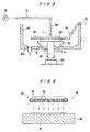
- FIGS. 7 and 8 show the dispersed liquid supply device 42 for supplying the ultrafine particle dispersed liquid L (see FIG. 1B) to the surface of the substrate W.
- the dispersed liquid supply device 42 comprises a substrate holder 60 for holding and rotating the substrate W with its interconnecting forming surface (face side) oriented upwardly, and a bottomed cup-shaped scattering prevention plate 62 surrounding the substrate W that is held by the substrate holder 60.
- the substrate holder 60 has a vacuum chuck on its upper surface for attracting and holding the substrate W, and is connected to the upper end of a rotatable shaft 66 that extends from a servomotor 64 for rotation upon energization of the servomotor 64.
- the scattering prevention plate 62 is made of a material resistant to organic solvents, e.g., stainless steel.
- a downwardly directed dispersed liquid supply nozzle 68 for dropping the ultrafine particle dispersed liquid L is positioned upwardly of either the center of the surface of the substrate W that is held by the substrate holder 60 or a spot slightly off the center of the surface of the substrate W.
- the dispersed liquid supply nozzle 68 is connected to the free end of an arm 70.
- the arm 70 accommodates therein a pipe for supplying a metered amount of ultrafine particle dispersed liquid.
- the pipe extends from a metered amount supply device 72 such as a syringe pump or the like and is communicated with the dispersed liquid supply nozzle 68.
- a bevel washing nozzle 74 which is inclined downwardly inwardly is positioned above the circumferential area of the substrate W held by the substrate holder 60, for supplying a washing liquid to the bevel of the substrate W.
- a plurality of reverse side washing nozzles 76 which are inclined upwardly outwardly are positioned below the substrate W held by the substrate holder 60, for supplying a gas or washing liquid to the reverse side of the substrate W.
- the scattering prevention plate 62 has a drain hole 62a defined in its bottom.
- the substrate W is held by the substrate holder 60, and the servomotor 64 is energized to rotate the substrate W at a speed ranging from 300 to 500 rpm, for example, more preferably from 400 to 500 rpm. While the substrate W is being thus rotated, the dispersed liquid supply nozzle 68 drops a metered amount of ultrafine particle dispersed liquid L onto the central area of the surface of the substrate W. When the surface of the substrate W is covered with the ultrafine particle dispersed liquid L, the dropping of the ultrafine particle dispersed liquid L is stopped so that uniformly coat the surface of the substrate W with the ultrafine particle dispersed liquid L.
- the bevel washing nozzle 74 supplies a hydrophilic organic solvent such as methanol, acetone, or the like, or a washing liquid such as ethanol, isopropyl alcohol, or the like, to the bevel of the substrate W to prevent the ultrafine particle dispersed liquid L from dropping from the edge of the substrate W or flowing across the edge of the substrate W to the reverse side of the substrate W.
- the reverse side washing nozzles 76 also supplies a gas such as an N 2 gas, air, or the like, or a washing liquid which is the same as the washing liquid supplied to the bevel of the substrate W, to the reverse side of the substrate W to prevent a contamination of the reverse side of the substrate W using the gas flow or the washing liquid.
- the servomotor 4 rotates the substrate W to dry the substrate W in a spin drying process (air drying process) to evaporate the solvent in the ultrafine particle dispersed liquid L coated on the substrate W.
- the process of applying the ultrafine particle dispersed liquid L to the interconnection forming surface of the substrate W and spin-drying the substrate W is repeated a plurality of times as required. This process is put to an end when the small recesses (the contact hole 3 and the interconnection trench 4) are filled with a certain level by the ultrafine composite metal particle layer 6, i.e., the ultrafine composite metal particle layer 6 reaches a certain thickness.
- the substrate may be rotated at a higher speed to quicken the drying of the solvent.
- An excessive amount of ultrafine particle dispersed liquid L and the washing liquid that has been used to wash the bevel and reverse side of the substrate are discharged out of the drain hole 62a.
- FIG. 9 shows the supplementary drying device 46.
- the supplementary drying device 46 has a substrate holding base 80 for holding the substrate W with its face side oriented upwardly and a heat-treating device 84 disposed above the substrate holding base 80, the heat-treating device 84 comprising lamp heaters 82, for example.
- the supplementary drying device 46 serves to dry up the solvent that has not been evaporated by the spin drying process carried out by the dispersed liquid supply device 42.
- the supplementary drying device 46 may not necessarily be required if the solvent is sufficiently dried up by the spin-drying process carried out by the dispersed liquid supply device 42 such as when the solvent is coated as a very thin film.
- the ultrafine composite metal particle layer 6 (see FIG. 3A) deposited on the surface of the substrate W is heated while the organic solvent remains in the ultrafine composite metal particle layer 6, voids may possibly be produced at the bottoms of the trenches. Such voids are prevented from occurring by completely drying up the solvent with the supplementary drying device 46.
- the temperature to be achieved by the supplementary drying device 46 is preferably a temperature at which the ultrafine particles are not decomposed, e.g., about 100°C, for thereby preventing a contamination of the supplementary drying device 46 which would otherwise be caused by the decomposition of the ultrafine particles.
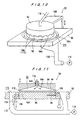
- FIGS. 10 through 13 show the heat-treating device 50 for heating the ultrafine composite metal particle layer 6 (see FIG. 3A) to melt and bond the metal together.
- the heat-treating device 50 has a heating plate 90 for holding and heating the substrate W with its face side directed upwardly, a housing 94 which surrounds a space above the substrate W that is held by the heating plate 90 to define a gas chamber 92 between the housing 94 and the heating plate 90, and a frame 96 which surrounds the heating plate 90.
- the heating plate 90 is made of aluminum or copper, for example, which has a high heat conductivity and can uniformly be heated at a high speed, and is in the form of a disk.
- the heating plate 90 houses therein a heater 78 and a temperature sensor 100 for detecting the temperature of the heating plate 90.
- the heating plate 90 also has a coolant flow passage 104 communicating with a coolant inlet passage 103 for introducing a coolant such as a cooling gas, air, or the like.
- the coolant flow passage 104 communicates with a coolant outlet passage 106.
- the housing 94 is made of ceramics, for example, and is fixed to the free end of a vertically movable arm 108.
- the housing 94 has a conical recess 94a defined in the reverse side thereof which provides the gas chamber 92 between itself and the substrate W placed on and held by the heating plate 90 when the housing 94 is displaced downwardly.
- the housing 94 has a gas supply port 94b defined centrally therein which is connected to a gas supply pipe 110.
- the housing 94 also has an alternately arranged succession of slits 94c and pressers 94d on its lower peripheral edge.
- the pressers 94d When the housing 94 is displaced downwardly, the pressers 94d are brought into abutment against the peripheral edge of the substrate W that is placed on and held by the heating plate 90, gripping and holing the peripheral edge of the substrate W between the heating plate 90 and the pressers 94d, and the slits 94c provide gas discharge ports 112.
- the frame 96 has a through hole 96a defined therein which provides a gas inlet port 114 with an inner surface thereof.
- a discharge duct 116 communicating with the gas inlet port 114 is fixed to the reverse side of the frame 96, and is connected to a discharge blower 118.
- the substrate W is placed on and held by the upper surface of the heating plate 90.
- the substrate W is heated to 300°C in 5 minutes, for example, held at 300°C for 5 minutes, and thereafter cooled to the room temperature in 10 minutes, thus melting and bonding the metal of ultrafine composite metal particles together.
- an inactive gas of N 2 or the like containing a small amount of oxygen or ozone is introduced from the gas supply pipe 110 into the gas chamber 92, and thereafter an inactive gas of only N 2 or the like is introduced from the gas supply pipe 110 into the gas chamber 92.
- the oxygen or ozone acts as a catalyst to separate the organic substance and the metal from each other, thus promoting the decomposition of the ultrafine composite metal particles.
- An oil mist produced when the ultrafine particles are decomposed is removed from the substrate surface by the N 2 gas, for example. Therefore, the oil mist is prevented from fuming and becoming stagnant on the substrate surface to contaminate the substrate.
- the oxygen or ozone may be added in a small quantity as it would undesirably oxidize the ultrafine particles if added in an excessive amount.
- the ultrafine composite metal particle layer be heated (baked) while a nitrogen gas containing a small amount of oxygen or ozone is flowing, and thereafter a nitrogen gas containing hydrogen is supplied to prevent the silver from being oxidized and reduce the silver to form interconnections of pure silver, after which the gas is changed to a nitrogen gas. In this manner, the interconnections can be formed efficiently.
- FIG. 14 shows the polishing device 54 which chemically and mechanically polishes the surface of the substrate W to remove excessively attached metal therefrom.
- the polishing device 54 comprises a polishing table 122 with a polishing cloth (polishing pad) 120 attached to its upper surface to provide a polishing surface, and a top ring 124 for holding the substrate W with its surface to be polished being directed toward the polishing table 122.
- the polishing table 122 and the top ring 124 are rotated about their respective own axes.
- the top ring 124 presses the substrate W under a constant pressure against the polishing cloth 120 on the polishing table 122, thereby polishing the surface of the substrate W.
- the abrasive liquid supplied from the abrasive liquid nozzle 126 comprises, for example, an alkaline solution containing a suspended abrasive grain which comprises fine particles of silica or the like. Therefore, the substrate W is polished to a flat and mirror finish by a chemical and mechanical polishing process based on a combination of a chemical polishing action of the alkali and a mechanical polishing action of the abrasive grain.
- the polishing power of the polishing surface of the polishing cloth 120 is lowered.
- a dresser 128 is provided.
- the polishing cloth 120 is dressed by the dresser 128, for example, when the substrate W is replaced with another substrate to be polished.
- a dressing surface (dressing member) of the dresser 128 is pressed against the polishing cloth 120 on the polishing table 122, and the dresser 128 and the polishing table 122 are rotated about their respective own axes to remove the abrasive liquid and abatement attached to the polishing surface, and also to planarize and dress the polishing surface for thereby regenerate the polishing surface.
- the apparatus for forming an interconnection operates as follows:
- the cassette 28 with substrates W housed therein is placed in the inlet/outlet port 30, and one substrate W is taken out of the cassette 28 and delivered to the dispersed liquid supply device 42 in the dispersed liquid supply section 44.
- the surface of the substrate W is supplied with the ultrafine particle dispersed liquid L and then spin-dried, and this process is repeated a plurality of times as required until the ultrafine composite metal particle layer 6 (see FIG. 3A) reaches a predetermined thickness.
- the substrate W is delivered to the supplementary drying device 46 in the supplementary drying section 48.
- the solvent in the ultrafine composite metal particle layer 6 is evaporated.
- the substrate W is delivered to the heat-treating device 46 in the heat-treating section 48.
- the ultrafine composite metal particle layer 6 (see FIG. 3A) is heated to melt and bond the metal together, thus forming the metal interconnection 7 (see FIG. 3B).
- the substrate W with the metal interconnection 7 formed thereon is then delivered to the polishing device 54 in the polishing section 56.
- the surface of the substrate W is chemically and mechanically polished to remove excessive metal therefrom.
- the substrate W is then returned to the cassette 28.
- the apparatus for forming an interconnection is capable of successively performing the above steps in the sequence.
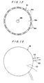
- FIG. 15 shows another example of an apparatus for forming an interconnection.
- the apparatus comprises a central transfer chamber 132 having a transfer robot 130 disposed therein, a dispersed liquid supply chamber 134 housing a dispersed liquid supply device 42 therein, a supplementary drying chamber 136 housing a supplementary drying device 46 therein, a heat-treating chamber 138 housing the heat-treating device 50 therein, a polishing chamber 140 housing the polishing device 54 therein, and plurality of stockyards (temporary placing chambers) 142 disposed in given positions between these chambers.
- the dispersed liquid supply chamber 134, the supplementary drying chamber 136, the heat-treating chamber 138, the polishing chamber 140, and the stockyards 142 are disposed radially around the central transfer chamber 132.
- the apparatus also has a second transfer chamber 148 having a mobile robot 146 disposed therein, the second transfer chamber 148 being positioned between a loading/unloading chamber 144 and the central transfer chamber 132.
- the dispersed liquid supply chamber 134 housing the dispersed liquid supply device 42 therein, the supplementary drying chamber 136 housing the supplementary drying device 46 therein, and the other chambers can be constructed as units. Furthermore, various processes including a dispersed liquid supply process, a supplementary drying process, etc. can be individually performed and can be combined to carry out a process of forming an interconnection.
- Oleic acid was used as an organic anionic substance, and silver acetate was used as a metal source.
- 0.5 L of a naphthene-based high boiling solvent having a distilling point of 250°C was placed into an eggplant-shaped flask having a volume of 1 L, and 10 g of silver acetate and 20 g of oleic acid were added to the solvent.
- the mixture was then heated at 240°C for 3 hours. As the mixture is heated, its color changed from colorless to light brown to purple. After the mixture was heated, acetone was added to the mixture, and the mixture was then refined by way of precipitation.
- the modified powder was observed by a transmissive electron microscope. The observation indicated that the powder was composed of ultrafine metal particles having a diameter of about 10 nm. An X-ray powder diffraction process conducted on the powder confirmed cores of metal silver.
- the powder composed of ultrafine metal particles was then dispersed in toluene and xylene. No precipitation was recognized in either of the solutions, which appeared to be transparent. In other words, the powder was dissolvable.
- the dispersion was used as an ultrafine particle dispersed liquid, and coated on a semiconductor substrate having fine recesses at a ratio of 0.05 g per 1 cm 2 . After the semiconductor substrate was dried, it was heated at about 250°C in a nitrogen atmosphere. The ultrafine composite metal particles in the fine recesses were easily melted and silver interconnections were formed. The silver interconnections were measured for their resistance, which was 1.8 ⁇ ⁇ ⁇ cm.
- the semiconductor substrate was chemically and mechanically polished using an abrasive grain of silica, well planarizing the silver interconnections in the recesses without peel-off.
- Stearic acid was used as an organic anionic substance, and copper carbonate was used as a metal source.
- 0.5 L of a paraffin-based high boiling solvent having a distilling point of 250°C was placed into an eggplant-shaped flask having a volume of 1 L, and 10 g of copper carbonate and 40 g of stearic acid were added to the solvent.
- the mixture was then heated at 300°C for 3 hours. As the mixture is heated, its color changed from light green to dark green to brown. After the mixture was heated, methanol was added to the mixture, and the mixture was then refined by way of precipitation.
- the powder composed of ultrafine metal particles was then applied to a substrate in the same manner as with Example 1. However, the substrate was heated at 300°C. The ultrafine composite metal particles in the fine recesses were easily melted into copper interconnections. When the substrate was chemically and mechanically polished, the copper interconnections were well planarized without peel-off.
- Sodium dodecylbenzenesulfonate was used as an organic anionic substance, and gold carbonate was used as a metal source.
- 0.5 L of xylene (isomer mixture) was placed into an eggplant-shaped flask having a volume of 1 L, and 5 of gold carbonate and 20 g of sodium dodecylbenzenesulfonate were added to the solvent.
- the mixture was then heated at 150°C for 3 hours. As the mixture is heated, its color changed from yellow to light brown to red. After the mixture was heated, acetone was added to the mixture, and the mixture was then refined by way of precipitation.
- the powder composed of ultrafine metal particles was then applied to a substrate in the same manner as with Example 1. However, the substrate was heated at 200°C. The ultrafine composite metal particles in the fine recesses were easily melted into copper interconnections. When the substrate was chemically and mechanically polished, the copper interconnections were well planarized without peel-off.
- the present invention as described above, it is possible to stably deposit an interconnection metal of good quality using ultrafine particles which contain the metal at least partly.
- the process can be used as a method of forming an interconnection to meet requirements for highly integrated semiconductor circuits, thus contributing the progress of a process of fabricating semiconductor devices.
- the present invention relates to a method of and an apparatus for forming an interconnection, and more particularly to a method of and an apparatus for forming a fine interconnection in a highly integrated circuit formed on a semiconductor substrate.
- the method can be used as a method of forming an interconnection to meet requirements for highly integrated semiconductor circuits, thus contributing the progress of a process of fabricating semiconductor devices.
Landscapes
- Chemical & Material Sciences (AREA)
- Engineering & Computer Science (AREA)
- Materials Engineering (AREA)
- General Chemical & Material Sciences (AREA)
- Chemical Kinetics & Catalysis (AREA)
- Thermal Sciences (AREA)
- Physics & Mathematics (AREA)
- Mechanical Engineering (AREA)
- Metallurgy (AREA)
- Organic Chemistry (AREA)
- Inorganic Chemistry (AREA)
- Manufacturing & Machinery (AREA)
- Microelectronics & Electronic Packaging (AREA)
- Internal Circuitry In Semiconductor Integrated Circuit Devices (AREA)
- Manufacturing Of Printed Wiring (AREA)
Abstract
The present invention relates particularly to a
method of and an apparatus for forming a fine
interconnection in a highly integrated circuit formed on a
semiconductor substrate. The method has the steps of
preparing a substrate having fine recesses formed in a
surface thereof, dispersing ultrafine particles made at
least partly of a metal in a predetermined solvent,
producing an ultrafine particle dispersed liquid, supplying
the ultrafine particle dispersed liquid to the fine recesses
of the substrate, heating the substrate to melt and bond the
metal, and chemical mechanical polishing the surface of the
substrate to remove an excessively attached metal therefrom.
According to the present invention, it is possible to stably
deposit an interconnection metal of good quality using an
inexpensive material.
Description
The present invention relates to a method of and
an apparatus for forming an interconnection, and more
particularly to a method of and an apparatus for forming a
fine interconnection in a highly integrated circuit formed
on a semiconductor substrate such as a semiconductor wafer
or the like.
Aluminum or aluminum alloy has generally been
used as a material for forming interconnection circuits on
semiconductor substrates. It has been customary to grow a
film of the material according to a process such as
sputtering, CVD, or the like and then produce a pattern in
the film according to etching or the like. As the level of
circuit integration increases in recent years, there is a
demand for the usage of silver, copper or its alloy, which
has a higher conductivity, as an interconnection material.
Since it is difficult to etch these materials, it has been
proposed to immerse a substrate having interconnection
pattern trenches therein in a plating liquid and perform
electrolytic or electroless plating on the substrate to
embed the trenches with silver, copper or its alloy.
However, while the plating processes are an
inexpensive and highly technically accomplished technology,
the electrolytic plating process is capable of growing a
film only on an electrically conductive material, whereas
the electroless plating process suffers a problem in that
substances contained in the plating liquid affect the
natural environment and the working environment.
Accordingly, there has been a strong need for the
development of a metal interconnection technology as a
substitute for the plating processes.
The present invention has been made in view of
the foregoing problems and demand. It is an object of the
present invention to provide a method of and an apparatus
for forming an interconnection by stably depositing an
interconnection metal of good quality as a substitute for
the conventional plating processes.
According to an invention described in claim 1,
there is provided a method of forming an interconnection,
comprising the steps of preparing a substrate having fine
recesses formed in a surface thereof, dispersing ultrafine
particles made at least partly of a metal in a predetermined
solvent, producing an ultrafine particle dispersed liquid,
supplying the ultrafine particle dispersed liquid to the
fine recesses of the substrate, heating the substrate to
melt and bond the metal, and chemical mechanical polishing
the surface of the substrate to remove an excessively
attached metal therefrom.
With the above arrangement, it is possible to
easily form interconnections according to so-called single
and dual damascene processes.
The ultrafine particle dispersed liquid may be
placed in a container, providing a liquid reservoir, and the
substrate may be immersed in the liquid reservoir to supply
the ultrafine particle dispersed liquid to only the fine
recesses of the substrate. Alternatively, the ultrafine
particle dispersed liquid may be supplied to the fine
recesses of the substrate by being coated or sprayed in the
fine recesses of the substrate and/or on areas surrounding
the fine recesses. Furthermore, the ultrafine particle
dispersed liquid may be coated by a spin coating process.
According to an invention described in claim 2,
the method according to claim 1 comprises the step of
evaporating the solvent between the step of supplying the
ultrafine particle dispersed liquid to the fine recesses of
the substrate and the step of heating the substrate to melt
and bond the metal.
According to an invention described in claim 3,
in the method according to claim 1 or 2, each of the
ultrafine particles comprises an ultrafine composite metal
particle comprising a core made substantially of a metal
component and a covering layer made of an organic substance
chemically bonded to the core.
For manufacturing ultrafine particles made at
least partly of a metal, there has been proposed a process
of evaporating the metal in a vacuum in the presence of a
small amount of a gas to agglomerate ultrafine particles
made of only the metal from the gas phase, producing
ultrafine metal particles. Such a physical process,
however, does not lend itself to mass production as the
amount of generated ultrafine metal particles is small, and
is costly because a device for generating an electron beam,
a plasma, or a laser beam, etc. or a device for performing
inductive heating is necessary to evaporate the metal. In
addition, since the particle diameters range in a wide
distribution, some of the metal particles remain unmelted
when heated, failing to obtain a uniform metal film of low
resistance.
When ultrafine particles made of only the metal
is used, the ultrafine particles tend to agglomerate in a
dispersed liquid, the ultrafine particle dispersed liquid is
liable to provide an irregular covering layer. One solution
would be to add a suitable surface active agent to the
ultrafine particle dispersed liquid to turn them into a
protective colloid. However, such a protective colloid
fails to provide sufficient dispersion stability.
The bonded structure of ultrafine composite metal
particles according to the present invention appears to be
such that a core made of a metal component and an organic
compound making up a covering layer share metal molecules,
or an organic compound and a core form a complex-analogous
structure by way of an ionic bond, through the details of
the bonded structure are not clear. Since such ultrafine
composite metal particles can be produced by a chemical
process in a liquid phase, they can be mass-produced at a
reduced cost in an ordinary atmospheric environment with a
simple apparatus without the need for a large vacuum device.
Since the ultrafine composite metal particles have a uniform
diameter, all the ultrafine composite metal particles are
fused together at a constant temperature. Inasmuch as the
ultrafine composite metal particles are covered with an
organic metal compound therearound, their ability to
agglomerate in a solvent is small, and hence they can easily
be scattered uniformly over the surface of the substrate.
The ultrafine composite metal particles are stable and hence
can easily be handled. Even after the solvent is
evaporated, the ultrafine composite metal particles remain
chemically stable until they are decomposed with heat and
can be handled for easy process management.
According to a method described in claim 4, in
the claim according to any one of claims 1 through 3, the
ultrafine particles have an average diameter ranging from 1
to 20 nm.
It is known that the melting point of a metal
particle is lowered as the diameter thereof is reduced.
This effect starts to manifest itself when the diameter of
the metal particle is 20 nm or less, and becomes distinctive
when the diameter of the metal particle is 10 nm or less.
Therefore, the average diameter of the ultrafine particles
are preferably in the range from 1 to 20 nm, and preferably
in the range from 1 to 10 nm depending on the shape and
dimensions of the fine recesses and the structure of the
semiconductor device.
According to a method described in claim 5, in
the method according to any one of claims 1 through 4, the
ultrafine particle dispersed liquid has a predetermined
surface tension to increase adhesiveness of the ultrafine
particle dispersed liquid to the fine recesses of the
substrate and/or areas surrounding the fine recesses.
With the ultrafine particle dispersed liquid
having a predetermined surface tension, the applicability of
the ultrafine particle dispersed liquid in the fine recesses
of the substrate and on areas surrounding the fine recesses
is increased. Thus, the substrate with a large amount of
liquid held thereon can be dried, so that a sufficient
amount of ultrafine particles can be supplied to the
recesses and the areas surrounding the fine recesses.
Consequently, it is not necessary to repeat the applying and
drying steps, and the fine recesses can be filled with the
metal according to a simple process.
According to an invention described in claim 6,
in the method according to any one of claims 1 through 5,
the step of heating the ultrafine particles is carried out
under the control of an atmosphere. With this arrangement,
an oil mist produced when the ultrafine particles are
decomposed is removed from the substrate surface by a
nitrogen gas, for example. Therefore, the oil mist is
prevented from fuming and becoming stagnant on the substrate
surface to contaminate the substrate.
According to an invention described in claim 7,
in the method according to claim 6, the step of heating the
substrate is carried out in an inactive gas atmosphere
containing a small amount of oxygen or ozone, and thereafter
in a pure inactive gas atmosphere. The oxygen or ozone acts
as a catalyst to separate the organic substance and the
metal from each other, thus promoting the decomposition of
the ultrafine particles. For example, when interconnections
are to be formed using ultrafine particles of silver, the
ultrafine composite metal particle layer is heated (baked)
while a nitrogen gas containing a small amount of oxygen or
ozone is flowing, and thereafter a nitrogen gas containing
hydrogen is supplied to reduce the silver to form
interconnections of pure copper, after which the gas is
changed to a nitrogen gas. In this manner, the
interconnections can be formed efficiently.
According to an invention described in claim 8,
in the method according to claim 6 or 7, the step of heating
the substrate is carried out at a temperature of 450°C or
lower. In this manner, any thermal effect on the
semiconductor substrate and circuits formed thereon can be
reduced.
According to an invention described in claim 9,
there is provided a method of fabricating a semiconductor
wafer by forming an interconnection on a surface of a
substrate using the method according to any one of claims 1
through 8.
According to an invention described in claim 10,
there is provided an apparatus for forming an
interconnection, comprising a dispersed liquid supply device
for supplying an ultrafine particle dispersed liquid
produced by dispersing ultrafine particles made at least
partly of a metal in a predetermined solvent, to a surface
of a substrate having fine recesses formed therein; and a
heat-treating device for heating the substrate to melt and
bond the metal.
According to an invention described in claim 11,
the apparatus according to claim 10 further comprises a
polishing device for chemical mechanical polishing the
surface of the substrate to remove an excessively attached
metal therefrom.
According to an invention described in claim 12,
in the apparatus according to claim 10 or 11, the dispersed
liquid supply device also evaporates the solvent in the
ultrafine particle dispersed liquid supplied to the surface
of the substrate.
According to an invention described in claim 13,
the apparatus according to any one of claims 10 through 12
further comprises a supplementary drying device for
supplementarily drying the solvent in the ultrafine particle
dispersed liquid supplied to the surface of the substrate.
With this arrangement, it is possible to completely dry up
an organic solvent which cannot be fully dried up by a spin
drying process (air drying process) using a spin coater or
the like, thus preventing voids from being produced in a
heating process.
According to an invention described in claim 14,
in the apparatus according to any one of claims 10 through
13, the heat-treating device is arranged to heat the
substrate under the control of an atmosphere.
According to an invention described in claim 15,
in the apparatus according to any one of claims 10 through
14, the heat-treating device has a heating plate which
houses a heater for heating the substrate at a temperature
of 450°C or lower and a cooling mechanism.
According to an invention described in claim 16,
in the apparatus according to any one of claims 10 through
15, the respective devices are sequentially arranged in an
indoor facility along a direction in which the substrate
moves. With this arrangement, corresponding steps can
successively be performed by the devices in the sequence.
According to an invention described in claim 17,
in the apparatus according to any one of claims 10 through
15, the respective devices are accommodated individually in
respective chambers disposed radially around a central
transfer chamber with a transfer robot disposed therein.
With this arrangement, corresponding steps can be
individually performed and can be combined with each other.
According to an invention described in claim 18,
in the apparatus according to any one of claims 10 through
17, each of the ultrafine particles comprises an ultrafine
composite metal particle comprising a core made
substantially of a metal component and a covering layer made
of an organic substance chemically bonded to the core.
According to an invention described in claim 19,
in the apparatus according to any one of claims 10 through
18, the ultrafine particles have an average diameter ranging
from 1 to 20 nm.
According to an invention described in claim 20,
there is provided a dispersed liquid supply device for
supplying an ultrafine particle dispersed liquid produced by
dispersing ultrafine particles made at least partly of a
metal in a predetermined solvent, to a surface of a
substrate, comprising: a substrate holder for holding and
rotating the substrate; a dispersed liquid supply nozzle for
dropping the ultrafine particle dispersed liquid to the
surface of the substrate held by the substrate holder at a
central portion thereof or an area surrounding the central
portion; a bevel washing nozzle for supplying a washing
liquid to a bevel of the substrate held by the substrate
holder; and a reverse side washing nozzle for supplying a
gas or a washing liquid to the reverse side of the substrate
held by the substrate holder.
While the substrate is being rotated, the
ultrafine particle dispersed liquid is dropped onto the
center of the surface of the substrate to uniformly coat the
surface of the substrate with the ultrafine particle
dispersed liquid. At the same time, the bevel washing
nozzle supplies the washing liquid to the bevel of the
substrate to prevent the ultrafine particle dispersed liquid
from dropping from the edge of the substrate and flowing
across the edge of the substrate to the reverse side of the
substrate. The reverse side washing nozzles also supplies
the gas or the washing liquid to the reverse side of the
substrate to prevent the reverse side of the substrate from
being contaminated.
According to an invention described in claim 21,
there is provided a heat-treating device for heating
ultrafine particles made at least partly of a metal to melt
and bond the metal, comprising a heating plate for holding
and heating the substrate, and a housing having a gas supply
port and a gas discharge port and surrounding a space above
the substrate held by the heating plate to form a gas
chamber between the housing and the heating plate.
By supplying a predetermined gas into and
discharging same from the gas chamber defined between the
heating plate and the housing, the ultrafine particles are
heated under the control of an atmosphere so that an oil
mist produced when the ultrafine particles are decomposed is
removed from the substrate surface, and prevented from
fuming and becoming stagnant on the substrate surface to
contaminate the substrate.
An embodiment according to the present invention
will be described below with reference to the drawings. The
embodiment will be used as one type of a so-called dual-damascene
process for forming interconnections of copper or
silver layers in fine recesses such as interconnection
trenches defined in the surface of a semiconductor substrate
and vertical holes, referred to as contact holes, that
interconnect layers.
FIGS. 1A through 1C show successive steps of a
method of forming an interconnection according to the
present invention. As shown in FIG. 1A, a semiconductor
substrate W includes a semiconductor base 1 with a
semiconductor device formed thereon, an electrically
conductive layer 1a disposed on the semiconductor base 1, an
insulating film 2 of SiO2 deposited on the electrically
conductive layer 1a and having a contact hole 3 and an
interconnection trench 4 defined therein by lithography and
etching, and a barrier layer 5 of TaN or the like deposited
on the surface formed so far.
An ultrafine particle dispersed liquid L (see
FIG. 1B) is prepared which comprises, as shown in FIGS. 2A
and 2B, ultrafine composite metal particles 14 each
comprising a core 10 substantially made of a metal component
and a covering layer 12 made of an organic compound and
dispersed in a given solvent. The ultrafine composite metal
particles 14 are stable because their cores 10 are covered
with the covering layers 12 of an organic compound, and have
a small tendency to agglomerate in the solvent.
The ratio of the metal component in the ultrafine
composite metal particles 14 usually ranges from 50 to 90
weight %. For use in interconnection trenches, the ratio of
the metal component in the ultrafine composite metal
particles 14 is usually in the range from 60 to 90 weight %,
and preferably in the range from 70 to 90 weight %.
Each of the ultrafine composite metal particles
14 is composed of an organic compound and a metal component
derived from a metal salt as a starting material, e.g.,
carbonate, formate, or acetate. Each of the ultrafine
composite metal particles 14 has its central region made of
the metal component and surrounded by the ionic organic
compound. At this time, the organic compound and the metal
component are chemically bonded partly or wholly to each
other, and exist in integral unity. The ultrafine composite
metal particles 14 have high stability and are stable at a
higher metal concentration unlike conventional ultrafine
metal particles which are stabilized by being coated with a
surface active agent.
The cores 10 of the ultrafine composite metal
particles 14 have an average diameter which usually ranges
from 1 to 20 nm and preferably from 1 to 10 nm.
The ultrafine composite metal particles 14 can be
manufactured by heating a metal salt, e.g., carbonate,
formate, or acetate, in a nonaqueous solvent in the presence
of an ionic organic substance at a temperature that is equal
to or higher than the decomposition reducing temperature of
the metal salt and also is equal to or lower than the
decomposition temperature of the ionic organic substance.
The metal component comprises at least one of Cu,
Ag, Au, Zn, In, Si, Sn, Pd, Fe, Co, Ni, Ru, Rh, Os, Ir, Pt,
Cr, Mo, Ba, Bi, Al, W, Ta, Ti, and Pb. The ionic organic
substance comprises a fatty acid having a carbon number of 5
or more, an alkylbenzene sulfonic acid, or an alkyl sulfonic
acid.
The heating temperature is equal to or higher
than the decomposition reducing temperature of the metal
salt, e.g., carbonate, formate, or acetate, and also is
equal to or lower than the decomposition temperature of the
ionic organic substance. For example, if acetate is used as
the metal salt, then since its decomposition starting
temperature is 200°C, the metal salt may be kept at a
temperature that is equal to or higher than 200°C and low
enough to keep the ionic organic substance from being
decomposed. To prevent the ionic organic substance from
being decomposed, the heating atmosphere should preferably
be an inactive gas atmosphere. However, the metal salt may
be heated in the atmosphere by selecting a nonaqueous
solvent.
For heating, various alcohols may be added for
accelerating the reaction. Such alcohols are not limited to
any particular alcohols, but may be lauryl alcohol,
glycerin, ethylene alcohol, or the like, for example,
insofar as they can accelerate the reaction. The amount of
the added alcohol may be determined depending on the type of
the added alcohol. Usually, the alcohol is added in 5
through 20 parts by weight, preferably 5 through 10 parts by
weight, with respect to 100 parts by weight of the metal
salt.
After the heating, the ultrafine composite metal
particles 14 are refined according to a known refining
process. The refining process includes a centrifugal
separation process, a film refining process, a solvent
extracting process, or the like, for example.
The ultrafine composite metal particles 14 thus
produced are dispersed in a suitable solvent, producing the
ultrafine particle dispersed liquid L. Since the ultrafine
composite metal particles 14 as dispersed particles are very
small, the ultrafine particle dispersed liquid L is
substantially transparent when the ultrafine composite metal
particles 14 are mixed and stirred. Properties of the
ultrafine particle dispersed liquid L such as surface
tension, viscosity, etc. may be adjusted by appropriately
selecting the type of the solvent, the concentration of the
ultrafine composite metal particles and temperature, etc.
The ultrafine particle dispersed liquid L is
dropped onto the substrate W at its center or a spot
slightly off the center according to a spin coating process,
i.e., while the substrate W is being rotated, for example.
When the ultrafine particle dispersed liquid L has covered
the surface of the substrate W, the dropping of the
ultrafine particle dispersed liquid L is stopped, thus
uniformly coating the entire interconnection forming surface
of the substrate W, as shown in FIG. 1B. In this manner, a
liquid film having a given thickness that is determined by
the viscosity of the ultrafine particle dispersed liquid L
and the surface tension acting between the substrate surface
and the ultrafine particle dispersed liquid L is formed on
the substrate surface.
While the ultrafine particle dispersed liquid L
is being kept from dropping, the substrate W is rotated in a
spin drying process (air drying process) to evaporate the
solvent in the ultrafine particle dispersed liquid L, thus
forming an ultrafine composite metal particle layer 6, which
comprises an agglomeration of ultrafine composite metal
particles as a solid material, in the small recesses (the
contact hole 3 and the interconnection trench 4) and on the
substrate surface, as shown in FIG. 1C.
Alternatively, a liquid film having a given
thickness may be formed on the interconnection forming
surface of the substrate W by immersing the substrate W in
the ultrafine particle dispersed liquid L according to a
dipping process. In this process, undesired areas of the
substrate W may be masked, and the ultrafine particle
dispersed liquid L may be stirred, or the ultrafine particle
dispersed liquid L or the substrate W may be vibrated in
order to fill the small recesses (the contact hole 3 and the
interconnection trench 4) with the ultrafine particle
dispersed liquid L.
The process of applying the ultrafine particle
dispersed liquid L to the interconnection forming surface of
the substrate W and spin-drying the substrate W is repeated
a plurality of times as required. The immersing and drying
process is put to an end when the small recesses (the
contact hole 3 and the interconnection trench 4) are filled
to a certain level with the ultrafine composite metal
particle layer 6. Thereafter, the ultrafine composite metal
particle layer 6 is decomposed with heat in a controlled
atmosphere by a heating furnace to melt and bond the
ultrafine composite metal particles together, thus forming a
metal interconnection 7, as shown in FIG. 3B.
Specifically, the ultrafine composite metal
particle layer 6 is heated to 300°C in 5 minutes, held at
300°C for 5 minutes, and thereafter cooled to the room
temperature in 10 minutes. This heating process is first
carried out in an inactive gas atmosphere of N2 or the like
containing a small amount of oxygen or ozone, and thereafter
carried out in a pure inactive gas atmosphere of only N2 or
the like. The oxygen or ozone acts as a catalyst to
separate the organic substance and the metal from each
other, thus promoting the decomposition of the ultrafine
particles. An oil mist produced when the ultrafine
particles are decomposed is removed from the substrate
surface by the N2 gas, for example. Therefore, the oil mist
is prevented from fuming and becoming stagnant on the
substrate surface to contaminate the substrate.
When interconnections are to be formed using
ultrafine particles of silver, it is preferable that the
ultrafine composite metal particle layer be heated (baked)
while a nitrogen gas containing a small amount of oxygen or
ozone is flowing, and thereafter a nitrogen gas containing
hydrogen is supplied to prevent the silver from being
oxidized and reduce the silver to form interconnections of
pure silver, after which the gas is changed to a nitrogen
gas. In this manner, the interconnections can be formed
efficiently.
By decomposing the ultrafine composite metal
particle layer with heat at a temperature of 450°C or lower,
any thermal effect on the semiconductor substrate and
circuits formed thereon can be reduced.
Then, as shown in FIG. 3C, the substrate is
chemically and mechanically polished to remove the metal and
the barrier layer that have been attached to the substrate
surface. Thus, excessive interconnection fractions are
removed. An insulating layer may be formed over the metal
interconnection 7, and a structure as shown in FIG. 1A may
be formed again on the insulating layer, after which the
above steps may be repeated to produce a multilayer
interconnection structure.
In the above embodiment, ultrafine composite
metal particles are used as ultrafine particles, and
dispersed in a solvent to produce an ultrafine particle
dispersed liquid. However, the ultrafine composite metal
particles may be replaced with generally known ultrafine
particles made of metal only, and those ultrafine particles
made of metal only may be dispersed in a solvent to produce
an ultrafine particle dispersed liquid. Such a modification
is also applicable to an apparatus for forming an
interconnection to be described below.
An apparatus for forming an interconnection
according to the present invention, which is used to carry
out the above method of forming an interconnection, will be
described below with reference to FIGS. 4 through 15.
FIG. 4 shows a rectangular indoor facility 20
which incorporates an apparatus for forming an
interconnection therein. The indoor facility 20 has on its
ceiling a discharge duct 22 for discharging exhaust gases in
a dispersed liquid supply section 44 and a supplementary
drying section 48, described below, a discharge duct 24 for
discharging exhaust gases in a heat-treating section 52, and
an air-conditioning unit 26 for air-conditioning a polishing
section 56, etc. The indoor facility 20 also has an
inlet/outlet port 30 defined in a side wall thereof for
introducing and removing a cassette 28 with substrates W
housed therein and a control panel 32 mounted on the side
wall.
As shown in FIG. 5, for example, the indoor
facility 20 is disposed in a utility zone 34 in a clean
room. The indoor facility 20 has an end positioned in an
opening defined in a partition wall 38 which divides the
utility zone 34 and a clean zone 36 from each other, with
the inlet/outlet port 30 and the control panel 32 being
exposed in the clean zone 36. The discharge ducts 22, 24
are connected to a common discharge duct 25 that extends out
of the utility zone 34.
As shown in FIG. 6, the indoor facility 20 has
its interior divided into a loading/unloading section 40
having the inlet/outlet port 30, a dispersed liquid supply
section 44 housing a dispersed liquid supply device 42
therein, a supplementary drying section 48 housing a
supplementary drying device 46 therein, a heat-treating
section 52 housing a heat-treating device 50 therein, and a
polishing section 56 housing a polishing device 54 therein.
These devices 42, 46, 50, 54 are arranged in a sequence
along the direction in which the substrate flows, so that a
series of interconnection forming steps can successively be
performed on the substrate. The dispersed liquid supply
section 44 and the supplementary drying device 46 are of an
explosion-proof structure in view of the explosiveness of an
organic solvent.
In the present embodiment, the indoor facility 20
has a single inlet/outlet port for storing one cassette
therein. However, the indoor facility may have two
inlet/outlet ports for storing respective cassettes therein.
FIGS. 7 and 8 show the dispersed liquid supply
device 42 for supplying the ultrafine particle dispersed
liquid L (see FIG. 1B) to the surface of the substrate W.
The dispersed liquid supply device 42 comprises a substrate
holder 60 for holding and rotating the substrate W with its
interconnecting forming surface (face side) oriented
upwardly, and a bottomed cup-shaped scattering prevention
plate 62 surrounding the substrate W that is held by the
substrate holder 60. The substrate holder 60 has a vacuum
chuck on its upper surface for attracting and holding the
substrate W, and is connected to the upper end of a
rotatable shaft 66 that extends from a servomotor 64 for
rotation upon energization of the servomotor 64. The
scattering prevention plate 62 is made of a material
resistant to organic solvents, e.g., stainless steel.
A downwardly directed dispersed liquid supply
nozzle 68 for dropping the ultrafine particle dispersed
liquid L is positioned upwardly of either the center of the
surface of the substrate W that is held by the substrate
holder 60 or a spot slightly off the center of the surface
of the substrate W. The dispersed liquid supply nozzle 68
is connected to the free end of an arm 70. The arm 70
accommodates therein a pipe for supplying a metered amount
of ultrafine particle dispersed liquid. The pipe extends
from a metered amount supply device 72 such as a syringe
pump or the like and is communicated with the dispersed
liquid supply nozzle 68.
A bevel washing nozzle 74 which is inclined
downwardly inwardly is positioned above the circumferential
area of the substrate W held by the substrate holder 60, for
supplying a washing liquid to the bevel of the substrate W.
A plurality of reverse side washing nozzles 76 which are
inclined upwardly outwardly are positioned below the
substrate W held by the substrate holder 60, for supplying a
gas or washing liquid to the reverse side of the substrate
W. The scattering prevention plate 62 has a drain hole 62a
defined in its bottom.
Therefore, the substrate W is held by the
substrate holder 60, and the servomotor 64 is energized to
rotate the substrate W at a speed ranging from 300 to 500
rpm, for example, more preferably from 400 to 500 rpm.
While the substrate W is being thus rotated, the dispersed
liquid supply nozzle 68 drops a metered amount of ultrafine
particle dispersed liquid L onto the central area of the
surface of the substrate W. When the surface of the
substrate W is covered with the ultrafine particle dispersed
liquid L, the dropping of the ultrafine particle dispersed
liquid L is stopped so that uniformly coat the surface of
the substrate W with the ultrafine particle dispersed liquid
L. At the same time, the bevel washing nozzle 74 supplies a
hydrophilic organic solvent such as methanol, acetone, or
the like, or a washing liquid such as ethanol, isopropyl
alcohol, or the like, to the bevel of the substrate W to
prevent the ultrafine particle dispersed liquid L from
dropping from the edge of the substrate W or flowing across
the edge of the substrate W to the reverse side of the
substrate W. The reverse side washing nozzles 76 also
supplies a gas such as an N2 gas, air, or the like, or a
washing liquid which is the same as the washing liquid
supplied to the bevel of the substrate W, to the reverse
side of the substrate W to prevent a contamination of the
reverse side of the substrate W using the gas flow or the
washing liquid.
With the dropping of the ultrafine particle
dispersed liquid L being stopped, the servomotor 4 rotates
the substrate W to dry the substrate W in a spin drying
process (air drying process) to evaporate the solvent in the
ultrafine particle dispersed liquid L coated on the
substrate W.
The process of applying the ultrafine particle
dispersed liquid L to the interconnection forming surface of
the substrate W and spin-drying the substrate W is repeated
a plurality of times as required. This process is put to an
end when the small recesses (the contact hole 3 and the
interconnection trench 4) are filled with a certain level by
the ultrafine composite metal particle layer 6, i.e., the
ultrafine composite metal particle layer 6 reaches a certain
thickness.
Finally, the substrate may be rotated at a higher
speed to quicken the drying of the solvent. An excessive
amount of ultrafine particle dispersed liquid L and the
washing liquid that has been used to wash the bevel and
reverse side of the substrate are discharged out of the
drain hole 62a.
FIG. 9 shows the supplementary drying device 46.
The supplementary drying device 46 has a substrate holding
base 80 for holding the substrate W with its face side
oriented upwardly and a heat-treating device 84 disposed
above the substrate holding base 80, the heat-treating
device 84 comprising lamp heaters 82, for example.
The supplementary drying device 46 serves to dry
up the solvent that has not been evaporated by the spin
drying process carried out by the dispersed liquid supply
device 42. The supplementary drying device 46 may not
necessarily be required if the solvent is sufficiently dried
up by the spin-drying process carried out by the dispersed
liquid supply device 42 such as when the solvent is coated
as a very thin film.
Specifically, if the ultrafine composite metal
particle layer 6 (see FIG. 3A) deposited on the surface of
the substrate W is heated while the organic solvent remains
in the ultrafine composite metal particle layer 6, voids may
possibly be produced at the bottoms of the trenches. Such
voids are prevented from occurring by completely drying up
the solvent with the supplementary drying device 46. The
temperature to be achieved by the supplementary drying
device 46 is preferably a temperature at which the ultrafine
particles are not decomposed, e.g., about 100°C, for thereby
preventing a contamination of the supplementary drying
device 46 which would otherwise be caused by the
decomposition of the ultrafine particles.
FIGS. 10 through 13 show the heat-treating device
50 for heating the ultrafine composite metal particle layer
6 (see FIG. 3A) to melt and bond the metal together. The
heat-treating device 50 has a heating plate 90 for holding
and heating the substrate W with its face side directed
upwardly, a housing 94 which surrounds a space above the
substrate W that is held by the heating plate 90 to define a
gas chamber 92 between the housing 94 and the heating plate
90, and a frame 96 which surrounds the heating plate 90.
The heating plate 90 is made of aluminum or
copper, for example, which has a high heat conductivity and
can uniformly be heated at a high speed, and is in the form
of a disk. The heating plate 90 houses therein a heater 78
and a temperature sensor 100 for detecting the temperature
of the heating plate 90. The heating plate 90 also has a
coolant flow passage 104 communicating with a coolant inlet
passage 103 for introducing a coolant such as a cooling gas,
air, or the like. The coolant flow passage 104 communicates
with a coolant outlet passage 106.
The housing 94 is made of ceramics, for example,
and is fixed to the free end of a vertically movable arm
108. The housing 94 has a conical recess 94a defined in the
reverse side thereof which provides the gas chamber 92
between itself and the substrate W placed on and held by the
heating plate 90 when the housing 94 is displaced
downwardly. Furthermore, the housing 94 has a gas supply
port 94b defined centrally therein which is connected to a
gas supply pipe 110. The housing 94 also has an alternately
arranged succession of slits 94c and pressers 94d on its
lower peripheral edge. When the housing 94 is displaced
downwardly, the pressers 94d are brought into abutment
against the peripheral edge of the substrate W that is
placed on and held by the heating plate 90, gripping and
holing the peripheral edge of the substrate W between the
heating plate 90 and the pressers 94d, and the slits 94c
provide gas discharge ports 112.
The frame 96 has a through hole 96a defined
therein which provides a gas inlet port 114 with an inner
surface thereof. A discharge duct 116 communicating with
the gas inlet port 114 is fixed to the reverse side of the
frame 96, and is connected to a discharge blower 118.
Therefore, the substrate W is placed on and held
by the upper surface of the heating plate 90. The substrate
W is heated to 300°C in 5 minutes, for example, held at
300°C for 5 minutes, and thereafter cooled to the room
temperature in 10 minutes, thus melting and bonding the
metal of ultrafine composite metal particles together. At
this time, an inactive gas of N2 or the like containing a
small amount of oxygen or ozone is introduced from the gas
supply pipe 110 into the gas chamber 92, and thereafter an
inactive gas of only N2 or the like is introduced from the
gas supply pipe 110 into the gas chamber 92. The oxygen or
ozone acts as a catalyst to separate the organic substance
and the metal from each other, thus promoting the
decomposition of the ultrafine composite metal particles.
An oil mist produced when the ultrafine particles are
decomposed is removed from the substrate surface by the N2
gas, for example. Therefore, the oil mist is prevented from
fuming and becoming stagnant on the substrate surface to
contaminate the substrate.
The oxygen or ozone may be added in a small
quantity as it would undesirably oxidize the ultrafine
particles if added in an excessive amount.
When interconnections are to be formed using
ultrafine particles of silver, it is preferable that the
ultrafine composite metal particle layer be heated (baked)
while a nitrogen gas containing a small amount of oxygen or
ozone is flowing, and thereafter a nitrogen gas containing
hydrogen is supplied to prevent the silver from being
oxidized and reduce the silver to form interconnections of
pure silver, after which the gas is changed to a nitrogen
gas. In this manner, the interconnections can be formed
efficiently.
FIG. 14 shows the polishing device 54 which
chemically and mechanically polishes the surface of the
substrate W to remove excessively attached metal therefrom.
The polishing device 54 comprises a polishing table 122 with
a polishing cloth (polishing pad) 120 attached to its upper
surface to provide a polishing surface, and a top ring 124
for holding the substrate W with its surface to be polished
being directed toward the polishing table 122. The
polishing table 122 and the top ring 124 are rotated about
their respective own axes. While the polishing cloth 120 is
being supplied with an abrasive liquid from an abrasive
liquid nozzle 126 disposed above the polishing table 122,
the top ring 124 presses the substrate W under a constant
pressure against the polishing cloth 120 on the polishing
table 122, thereby polishing the surface of the substrate W.
The abrasive liquid supplied from the abrasive liquid nozzle
126 comprises, for example, an alkaline solution containing
a suspended abrasive grain which comprises fine particles of
silica or the like. Therefore, the substrate W is polished
to a flat and mirror finish by a chemical and mechanical
polishing process based on a combination of a chemical
polishing action of the alkali and a mechanical polishing
action of the abrasive grain.
When the polishing device 54 continuously
performs the polishing process, the polishing power of the
polishing surface of the polishing cloth 120 is lowered. To
recover the polishing power, a dresser 128 is provided. The
polishing cloth 120 is dressed by the dresser 128, for
example, when the substrate W is replaced with another
substrate to be polished. In the dressing process, a
dressing surface (dressing member) of the dresser 128 is
pressed against the polishing cloth 120 on the polishing
table 122, and the dresser 128 and the polishing table 122
are rotated about their respective own axes to remove the
abrasive liquid and abatement attached to the polishing
surface, and also to planarize and dress the polishing
surface for thereby regenerate the polishing surface.
The apparatus for forming an interconnection,
thus constructed, operates as follows: The cassette 28 with
substrates W housed therein is placed in the inlet/outlet
port 30, and one substrate W is taken out of the cassette 28
and delivered to the dispersed liquid supply device 42 in
the dispersed liquid supply section 44. In the dispersed
liquid supply device 42, the surface of the substrate W is
supplied with the ultrafine particle dispersed liquid L and
then spin-dried, and this process is repeated a plurality of
times as required until the ultrafine composite metal
particle layer 6 (see FIG. 3A) reaches a predetermined
thickness. Then, the substrate W is delivered to the
supplementary drying device 46 in the supplementary drying
section 48. In the supplementary drying device 46, the
solvent in the ultrafine composite metal particle layer 6 is
evaporated. Then, the substrate W is delivered to the heat-treating
device 46 in the heat-treating section 48. In the
heat-treating device 46, the ultrafine composite metal
particle layer 6 (see FIG. 3A) is heated to melt and bond
the metal together, thus forming the metal interconnection 7
(see FIG. 3B).
The substrate W with the metal interconnection 7
formed thereon is then delivered to the polishing device 54
in the polishing section 56. In the polishing device 54,
the surface of the substrate W is chemically and
mechanically polished to remove excessive metal therefrom.
The substrate W is then returned to the cassette 28. The
apparatus for forming an interconnection is capable of
successively performing the above steps in the sequence.
FIG. 15 shows another example of an apparatus for
forming an interconnection. The apparatus comprises a
central transfer chamber 132 having a transfer robot 130
disposed therein, a dispersed liquid supply chamber 134
housing a dispersed liquid supply device 42 therein, a
supplementary drying chamber 136 housing a supplementary
drying device 46 therein, a heat-treating chamber 138
housing the heat-treating device 50 therein, a polishing
chamber 140 housing the polishing device 54 therein, and
plurality of stockyards (temporary placing chambers) 142
disposed in given positions between these chambers. The
dispersed liquid supply chamber 134, the supplementary
drying chamber 136, the heat-treating chamber 138, the
polishing chamber 140, and the stockyards 142 are disposed
radially around the central transfer chamber 132. The
apparatus also has a second transfer chamber 148 having a
mobile robot 146 disposed therein, the second transfer
chamber 148 being positioned between a loading/unloading
chamber 144 and the central transfer chamber 132.
With the above apparatus for forming an
interconnection, the dispersed liquid supply chamber 134
housing the dispersed liquid supply device 42 therein, the
supplementary drying chamber 136 housing the supplementary
drying device 46 therein, and the other chambers can be
constructed as units. Furthermore, various processes
including a dispersed liquid supply process, a supplementary
drying process, etc. can be individually performed and can
be combined to carry out a process of forming an
interconnection.
Oleic acid was used as an organic anionic
substance, and silver acetate was used as a metal source.
0.5 L of a naphthene-based high boiling solvent having a
distilling point of 250°C was placed into an eggplant-shaped
flask having a volume of 1 L, and 10 g of silver acetate and
20 g of oleic acid were added to the solvent. The mixture
was then heated at 240°C for 3 hours. As the mixture is
heated, its color changed from colorless to light brown to
purple. After the mixture was heated, acetone was added to
the mixture, and the mixture was then refined by way of
precipitation.
The modified powder was observed by a
transmissive electron microscope. The observation indicated
that the powder was composed of ultrafine metal particles
having a diameter of about 10 nm. An X-ray powder
diffraction process conducted on the powder confirmed cores
of metal silver.
The powder composed of ultrafine metal particles
(ultrafine composite metal particles) was then dispersed in
toluene and xylene. No precipitation was recognized in
either of the solutions, which appeared to be transparent.
In other words, the powder was dissolvable.
The dispersion was used as an ultrafine particle
dispersed liquid, and coated on a semiconductor substrate
having fine recesses at a ratio of 0.05 g per 1 cm2. After
the semiconductor substrate was dried, it was heated at
about 250°C in a nitrogen atmosphere. The ultrafine
composite metal particles in the fine recesses were easily
melted and silver interconnections were formed. The silver
interconnections were measured for their resistance, which
was 1.8 µ Ω · cm. The semiconductor substrate was chemically
and mechanically polished using an abrasive grain of silica,
well planarizing the silver interconnections in the recesses
without peel-off.
Stearic acid was used as an organic anionic
substance, and copper carbonate was used as a metal source.
0.5 L of a paraffin-based high boiling solvent having a
distilling point of 250°C was placed into an eggplant-shaped
flask having a volume of 1 L, and 10 g of copper carbonate
and 40 g of stearic acid were added to the solvent. The
mixture was then heated at 300°C for 3 hours. As the
mixture is heated, its color changed from light green to
dark green to brown. After the mixture was heated, methanol
was added to the mixture, and the mixture was then refined
by way of precipitation.
The powder composed of ultrafine metal particles
(ultrafine composite metal particles) was then applied to a
substrate in the same manner as with Example 1. However,
the substrate was heated at 300°C. The ultrafine composite
metal particles in the fine recesses were easily melted into
copper interconnections. When the substrate was chemically
and mechanically polished, the copper interconnections were
well planarized without peel-off.
Sodium dodecylbenzenesulfonate was used as an
organic anionic substance, and gold carbonate was used as a
metal source. 0.5 L of xylene (isomer mixture) was placed
into an eggplant-shaped flask having a volume of 1 L, and 5
of gold carbonate and 20 g of sodium dodecylbenzenesulfonate
were added to the solvent. The mixture was then heated at
150°C for 3 hours. As the mixture is heated, its color
changed from yellow to light brown to red. After the
mixture was heated, acetone was added to the mixture, and
the mixture was then refined by way of precipitation.
The powder composed of ultrafine metal particles
(ultrafine composite metal particles) was then applied to a
substrate in the same manner as with Example 1. However,
the substrate was heated at 200°C. The ultrafine composite
metal particles in the fine recesses were easily melted into
copper interconnections. When the substrate was chemically
and mechanically polished, the copper interconnections were
well planarized without peel-off.
According to the present invention, as described
above, it is possible to stably deposit an interconnection
metal of good quality using ultrafine particles which
contain the metal at least partly. The process can be used
as a method of forming an interconnection to meet
requirements for highly integrated semiconductor circuits,
thus contributing the progress of a process of fabricating
semiconductor devices.
The present invention relates to a method of and
an apparatus for forming an interconnection, and more
particularly to a method of and an apparatus for forming a
fine interconnection in a highly integrated circuit formed
on a semiconductor substrate. According to the present
invention, the method can be used as a method of forming an
interconnection to meet requirements for highly integrated
semiconductor circuits, thus contributing the progress of a
process of fabricating semiconductor devices.
Claims (21)
- A method of forming an interconnection, comprising the steps of:preparing a substrate having fine recesses formed in a surface thereof;dispersing ultrafine particles made at least partly of a metal in a predetermined solvent, producing an ultrafine particle dispersed liquid;supplying said ultrafine particle dispersed liquid to said fine recesses of said substrate;heating said substrate to melt and bond the metal; andchemical mechanical polishing the surface of the substrate to remove an excessively attached metal therefrom.
- A method according to claim 1, comprising the step of:
evaporating said solvent between said step of supplying said ultrafine particle dispersed liquid to said fine recesses of said substrate and said step of heating said substrate to melt and bond the metal. - A method according to claim 1 or 2, wherein each of said ultrafine particles comprises an ultrafine composite metal particle comprising a core made substantially of a metal component and a covering layer made of an organic substance chemically bonded to said core.
- A method according to any one of claims 1 through 3, wherein said ultrafine particles have an average diameter ranging from 1 to 20 nm.
- A method according to any one of claims 1 through 4, wherein said ultrafine particle dispersed liquid has a predetermined surface tension to increase adhesiveness of said ultrafine particle dispersed liquid to said fine recesses of said substrate and/or areas surrounding said fine recesses.
- A method according to any one of claims 1 through 5, wherein said step of heating said ultrafine particles is carried out under the control of an atmosphere.
- A method according to claim 6, wherein said step of heating said substrate is carried out in an inactive gas atmosphere containing a small amount of oxygen or ozone, and thereafter in a pure inactive gas atmosphere.
- A method according to claim 6 or 7, wherein said step of heating said substrate is carried out at a temperature of 450°C or lower.
- A method of fabricating a semiconductor wafer by forming an interconnection on a surface of a substrate using a method according to any one of claims 1 through 8.
- An apparatus for forming an interconnection, comprising:a dispersed liquid supply device for supplying an ultrafine particle dispersed liquid produced by dispersing ultrafine particles made at least partly of a metal in a predetermined solvent, to a surface of a substrate having fine recesses formed therein; anda heat-treating device for heating said substrate to melt and bond the metal.
- An apparatus according to claim 10, further comprising:
a polishing device for chemical mechanical polishing the surface of the substrate to remove an excessively attached metal therefrom. - An apparatus according to claim 10 or 11, wherein said dispersed liquid supply device also evaporates the solvent in said ultrafine particle dispersed liquid supplied to the surface of said substrate.
- An apparatus according to any one of claims 10 through 12, further comprising:
a supplementary drying device for supplementarily drying the solvent in said ultrafine particle dispersed liquid supplied to the surface of said substrate. - An apparatus according to any one of claims 10 through 13, wherein said heat-treating device is arranged to heat the substrate under the control of an atmosphere.
- An apparatus according to any one of claims 10 through 14, wherein said heat-treating device has a heating plate which houses a heater for heating the substrate at a temperature of 450°C or lower and a cooling mechanism.
- An apparatus according to any one of claims 10 through 15, wherein said respective devices are sequentially arranged in an indoor facility along a direction in which the substrate moves.
- An apparatus according to any one of claims 10 through 15, wherein said respective devices are accommodated individually in respective chambers disposed radially around a central transfer chamber with a transfer robot disposed therein.
- An apparatus according to any one of claims 10 through 17, wherein each of said ultrafine particles comprises an ultrafine composite metal particle comprising a core made substantially of a metal component and a covering layer made of an organic substance chemically bonded to said core.
- An apparatus according to any one of claims 10 through 18, wherein said ultrafine particles have an average diameter ranging from 1 to 20 nm.
- A dispersed liquid supply device for supplying an ultrafine particle dispersed liquid produced by dispersing ultrafine particles made at least partly of a metal in a predetermined solvent, to a surface of a substrate, comprising:a substrate holder for holding and rotating the substrate;a dispersed liquid supply nozzle for dropping the ultrafine particle dispersed liquid to the surface of the substrate held by said substrate holder at a central portion thereof or an area surrounding said central portion;a bevel washing nozzle for supplying a washing liquid to a bevel of the substrate held by said substrate holder; anda reverse side washing nozzle for supplying a gas or a washing liquid to the reverse side of the substrate held by said substrate holder.
- A heat-treating device for heating ultrafine particles made at least partly of a metal to melt and bond the metal, comprising:a heating plate for holding and heating the substrate; anda housing having a gas supply port and a gas discharge port, and surrounding a space above the substrate held by said heating plate to form a gas chamber between said housing and said heating plate.
Applications Claiming Priority (3)
| Application Number | Priority Date | Filing Date | Title |
|---|---|---|---|
| JP29450199 | 1999-10-15 | ||
| JP29450199 | 1999-10-15 | ||
| PCT/JP2000/007110 WO2001027983A1 (en) | 1999-10-15 | 2000-10-13 | Method and apparatus for forming interconnection |
Publications (2)
| Publication Number | Publication Date |
|---|---|
| EP1158573A1 true EP1158573A1 (en) | 2001-11-28 |
| EP1158573A4 EP1158573A4 (en) | 2008-09-24 |
Family
ID=17808599
Family Applications (1)
| Application Number | Title | Priority Date | Filing Date |
|---|---|---|---|
| EP00966463A Withdrawn EP1158573A4 (en) | 1999-10-15 | 2000-10-13 | METHOD AND APPARATUS FOR FORMING INTERCONNECTION |
Country Status (5)
| Country | Link |
|---|---|
| US (1) | US6730596B1 (en) |
| EP (1) | EP1158573A4 (en) |
| KR (1) | KR100741040B1 (en) |
| TW (1) | TW475199B (en) |
| WO (1) | WO2001027983A1 (en) |
Cited By (1)
| Publication number | Priority date | Publication date | Assignee | Title |
|---|---|---|---|---|
| TWI694492B (en) * | 2017-12-21 | 2020-05-21 | 南亞科技股份有限公司 | Method of forming fine interconnection for semiconductor devices |
Families Citing this family (16)
| Publication number | Priority date | Publication date | Assignee | Title |
|---|---|---|---|---|
| JP2002141351A (en) * | 2000-10-31 | 2002-05-17 | Japan Science & Technology Corp | Circuit board and its metal wiring forming method |
| JP2003093957A (en) * | 2001-09-25 | 2003-04-02 | Ulvac Japan Ltd | Method and apparatus for forming metallic thin film |
| JP3951750B2 (en) * | 2002-03-07 | 2007-08-01 | セイコーエプソン株式会社 | Substance filling method, film forming method, device and device manufacturing method |
| JP4081666B2 (en) * | 2002-09-24 | 2008-04-30 | セイコーエプソン株式会社 | Semiconductor device and manufacturing method thereof, circuit board, and electronic apparatus |
| JP4115306B2 (en) * | 2003-03-13 | 2008-07-09 | 富士通株式会社 | Manufacturing method of semiconductor device |
| US7854959B2 (en) * | 2003-03-31 | 2010-12-21 | Eidgenossische Technische Hochschule Zurich | Controlled surface chemical gradients |
| US20040248403A1 (en) * | 2003-06-09 | 2004-12-09 | Dubin Valery M. | Method for forming electroless metal low resistivity interconnects |
| JP4273871B2 (en) * | 2003-08-12 | 2009-06-03 | セイコーエプソン株式会社 | Wiring pattern forming method, semiconductor device manufacturing method, electro-optical device, and electronic apparatus |
| US20050048768A1 (en) * | 2003-08-26 | 2005-03-03 | Hiroaki Inoue | Apparatus and method for forming interconnects |
| US7253104B2 (en) * | 2003-12-01 | 2007-08-07 | Micron Technology, Inc. | Methods of forming particle-containing materials |
| JP2005203396A (en) * | 2004-01-13 | 2005-07-28 | Toshiba Corp | Electronic component manufacturing apparatus, electronic component manufacturing method, and electronic component |
| JP2007281416A (en) * | 2006-03-17 | 2007-10-25 | Seiko Epson Corp | Metal wiring forming method and active matrix substrate manufacturing method |
| JP5459896B2 (en) * | 2007-03-05 | 2014-04-02 | 株式会社半導体エネルギー研究所 | Wiring and memory element manufacturing method |
| KR101174881B1 (en) | 2010-06-11 | 2012-08-17 | 삼성디스플레이 주식회사 | Organic light emitting display and manufacturing method thereof |
| CN111013952A (en) * | 2018-10-10 | 2020-04-17 | 东莞市中图半导体科技有限公司 | Automatic glue homogenizing equipment and glue homogenizing method |
| CN116169096B (en) * | 2022-08-12 | 2024-08-13 | 本源量子计算科技(合肥)股份有限公司 | Method for preparing superconducting interconnect structure and method for preparing superconducting quantum circuit |
Family Cites Families (30)
| Publication number | Priority date | Publication date | Assignee | Title |
|---|---|---|---|---|
| JPS593952A (en) | 1982-06-30 | 1984-01-10 | Fujitsu Ltd | Formation of aluminum wiring layer |
| US4877647A (en) * | 1986-04-17 | 1989-10-31 | Kansas State University Research Foundation | Method of coating substrates with solvated clusters of metal particles |
| US5292393A (en) * | 1986-12-19 | 1994-03-08 | Applied Materials, Inc. | Multichamber integrated process system |
| JP2561537B2 (en) * | 1989-03-30 | 1996-12-11 | 真空冶金株式会社 | Metal paste and manufacturing method thereof |
| JPH03281783A (en) * | 1990-03-29 | 1991-12-12 | Vacuum Metallurgical Co Ltd | Formation of thin metallic film |
| JP3724592B2 (en) * | 1993-07-26 | 2005-12-07 | ハイニックス セミコンダクター アメリカ インコーポレイテッド | Method for planarizing a semiconductor substrate |
| US5559057A (en) * | 1994-03-24 | 1996-09-24 | Starfire Electgronic Development & Marketing Ltd. | Method for depositing and patterning thin films formed by fusing nanocrystalline precursors |
| US5560543A (en) * | 1994-09-19 | 1996-10-01 | Board Of Regents, The University Of Texas System | Heat-resistant broad-bandwidth liquid droplet generators |
| US5511608A (en) * | 1995-01-04 | 1996-04-30 | Boyd; Trace L. | Clampless vacuum heat transfer station |
| US5953629A (en) * | 1995-06-09 | 1999-09-14 | Vacuum Metallurgical Co., Ltd. | Method of thin film forming on semiconductor substrate |
| JPH09134891A (en) * | 1995-09-06 | 1997-05-20 | Vacuum Metallurgical Co Ltd | Formation of thin film of semiconductor substrate |
| JP3740207B2 (en) * | 1996-02-13 | 2006-02-01 | 大日本スクリーン製造株式会社 | Method for dissolving silica-based coating film formed on substrate surface |
| US5861066A (en) * | 1996-05-01 | 1999-01-19 | Ontrak Systems, Inc. | Method and apparatus for cleaning edges of contaminated substrates |
| KR100282160B1 (en) * | 1996-05-07 | 2001-03-02 | 가야시마 고조 | Substrate treatment device and processing method |
| JP2967734B2 (en) * | 1996-10-18 | 1999-10-25 | 日本電気株式会社 | Thin film formation method |
| JP3205793B2 (en) | 1996-12-19 | 2001-09-04 | 株式会社巴製作所 | Ultrafine particles and method for producing the same |
| TW347570B (en) * | 1996-12-24 | 1998-12-11 | Toshiba Co Ltd | Semiconductor device and method for manufacturing the same |
| JPH11152597A (en) | 1997-11-19 | 1999-06-08 | Ebara Corp | Plating pretreatment |
| US6544585B1 (en) | 1997-09-02 | 2003-04-08 | Ebara Corporation | Method and apparatus for plating a substrate |
| JPH1197392A (en) | 1997-09-16 | 1999-04-09 | Ebara Corp | Method and system for filling fine recess |
| TW405158B (en) * | 1997-09-17 | 2000-09-11 | Ebara Corp | Plating apparatus for semiconductor wafer processing |
| JPH11154653A (en) | 1997-09-17 | 1999-06-08 | Ebara Corp | Apparatus for plating substrates |
| US6328804B1 (en) * | 1998-07-10 | 2001-12-11 | Ball Semiconductor, Inc. | Chemical vapor deposition of metals on a spherical shaped semiconductor substrate |
| JP2002530520A (en) * | 1998-08-03 | 2002-09-17 | アドバンスド.テクノロジー.マテリアルズ.インコーポレイテッド | Copper precursor composition for the production of microelectronic device structures and its forming process |
| US6214259B1 (en) * | 1998-08-10 | 2001-04-10 | Vacuum Metallurgical Co., Ltd. | Dispersion containing Cu ultrafine particles individually dispersed therein |
| US6277740B1 (en) * | 1998-08-14 | 2001-08-21 | Avery N. Goldstein | Integrated circuit trenched features and method of producing same |
| US6294401B1 (en) * | 1998-08-19 | 2001-09-25 | Massachusetts Institute Of Technology | Nanoparticle-based electrical, chemical, and mechanical structures and methods of making same |
| JP2000173948A (en) | 1998-12-02 | 2000-06-23 | Ulvac Japan Ltd | Method and device for forming coat film |
| US6248658B1 (en) * | 1999-01-13 | 2001-06-19 | Advanced Micro Devices, Inc. | Method of forming submicron-dimensioned metal patterns |
| KR100358045B1 (en) * | 1999-12-22 | 2002-10-25 | 주식회사 하이닉스반도체 | Method of forming a copper wiring in a semiconductor device |
-
2000
- 2000-10-13 WO PCT/JP2000/007110 patent/WO2001027983A1/en not_active Ceased
- 2000-10-13 EP EP00966463A patent/EP1158573A4/en not_active Withdrawn
- 2000-10-13 US US09/868,140 patent/US6730596B1/en not_active Expired - Fee Related
- 2000-10-13 TW TW089121417A patent/TW475199B/en active
- 2000-10-13 KR KR1020017007338A patent/KR100741040B1/en not_active Expired - Fee Related
Cited By (1)
| Publication number | Priority date | Publication date | Assignee | Title |
|---|---|---|---|---|
| TWI694492B (en) * | 2017-12-21 | 2020-05-21 | 南亞科技股份有限公司 | Method of forming fine interconnection for semiconductor devices |
Also Published As
| Publication number | Publication date |
|---|---|
| WO2001027983A1 (en) | 2001-04-19 |
| KR20010093821A (en) | 2001-10-29 |
| US6730596B1 (en) | 2004-05-04 |
| KR100741040B1 (en) | 2007-07-20 |
| EP1158573A4 (en) | 2008-09-24 |
| TW475199B (en) | 2002-02-01 |
Similar Documents
| Publication | Publication Date | Title |
|---|---|---|
| US6972256B2 (en) | Method and apparatus for forming thin film of metal | |
| US6730596B1 (en) | Method of and apparatus for forming interconnection | |
| US7179503B2 (en) | Method of forming thin metal films on substrates | |
| US6743395B2 (en) | Composite metallic ultrafine particles and process for producing the same | |
| US7827930B2 (en) | Apparatus for electroless deposition of metals onto semiconductor substrates | |
| US6824612B2 (en) | Electroless plating system | |
| US7172979B2 (en) | Substrate processing apparatus and method | |
| US7654221B2 (en) | Apparatus for electroless deposition of metals onto semiconductor substrates | |
| KR100637890B1 (en) | Plating apparatus, plating method, plating process equipment | |
| TW200523391A (en) | Apparatus for electroless deposition | |
| CN1981070A (en) | Apparatus for electroless deposition of metals onto semiconductor substrates | |
| TW200800412A (en) | Apparatus for electroless deposition of metals onto semiconductor substrates | |
| US6709555B1 (en) | Plating method, interconnection forming method, and apparatus for carrying out those methods | |
| JP3812891B2 (en) | Wiring formation method | |
| TW200533424A (en) | Apparatus for electroless deposition of metals onto semiconductor substrates | |
| JPWO2001027983A1 (en) | Wiring forming method and apparatus | |
| JPWO2001041204A1 (en) | Metal thin film deposition method and device | |
| KR20060129410A (en) | Metal Electroless Deposition Apparatus on Semiconductor Substrate | |
| JPWO2001070435A1 (en) | Ultrafine composite metal particles and method for producing the same | |
| JP2000188266A (en) | Metal film forming apparatus and film forming method |
Legal Events
| Date | Code | Title | Description |
|---|---|---|---|
| PUAI | Public reference made under article 153(3) epc to a published international application that has entered the european phase |
Free format text: ORIGINAL CODE: 0009012 |
|
| 17P | Request for examination filed |
Effective date: 20010615 |
|
| AK | Designated contracting states |
Kind code of ref document: A1 Designated state(s): AT BE CH CY DE DK ES FI FR GB GR IE IT LI LU MC NL PT SE |
|
| RBV | Designated contracting states (corrected) |
Designated state(s): DE FR GB |
|
| A4 | Supplementary search report drawn up and despatched |
Effective date: 20080822 |
|
| 17Q | First examination report despatched |
Effective date: 20090225 |
|
| STAA | Information on the status of an ep patent application or granted ep patent |
Free format text: STATUS: THE APPLICATION IS DEEMED TO BE WITHDRAWN |
|
| 18D | Application deemed to be withdrawn |
Effective date: 20090708 |