EP1158508A2 - Magneto-optical recording medium and manufacturing method therefor - Google Patents
Magneto-optical recording medium and manufacturing method therefor Download PDFInfo
- Publication number
- EP1158508A2 EP1158508A2 EP00311787A EP00311787A EP1158508A2 EP 1158508 A2 EP1158508 A2 EP 1158508A2 EP 00311787 A EP00311787 A EP 00311787A EP 00311787 A EP00311787 A EP 00311787A EP 1158508 A2 EP1158508 A2 EP 1158508A2
- Authority
- EP
- European Patent Office
- Prior art keywords
- layer
- reproducing
- intermediate layer
- magnetic
- magneto
- Prior art date
- Legal status (The legal status is an assumption and is not a legal conclusion. Google has not performed a legal analysis and makes no representation as to the accuracy of the status listed.)
- Withdrawn
Links
Images



Classifications
-
- G—PHYSICS
- G11—INFORMATION STORAGE
- G11B—INFORMATION STORAGE BASED ON RELATIVE MOVEMENT BETWEEN RECORD CARRIER AND TRANSDUCER
- G11B11/00—Recording on or reproducing from the same record carrier wherein for these two operations the methods are covered by different main groups of groups G11B3/00 - G11B7/00 or by different subgroups of group G11B9/00; Record carriers therefor
- G11B11/10—Recording on or reproducing from the same record carrier wherein for these two operations the methods are covered by different main groups of groups G11B3/00 - G11B7/00 or by different subgroups of group G11B9/00; Record carriers therefor using recording by magnetic means or other means for magnetisation or demagnetisation of a record carrier, e.g. light induced spin magnetisation; Demagnetisation by thermal or stress means in the presence or not of an orienting magnetic field
- G11B11/105—Recording on or reproducing from the same record carrier wherein for these two operations the methods are covered by different main groups of groups G11B3/00 - G11B7/00 or by different subgroups of group G11B9/00; Record carriers therefor using recording by magnetic means or other means for magnetisation or demagnetisation of a record carrier, e.g. light induced spin magnetisation; Demagnetisation by thermal or stress means in the presence or not of an orienting magnetic field using a beam of light or a magnetic field for recording by change of magnetisation and a beam of light for reproducing, i.e. magneto-optical, e.g. light-induced thermomagnetic recording, spin magnetisation recording, Kerr or Faraday effect reproducing
- G11B11/10582—Record carriers characterised by the selection of the material or by the structure or form
- G11B11/10586—Record carriers characterised by the selection of the material or by the structure or form characterised by the selection of the material
-
- G—PHYSICS
- G11—INFORMATION STORAGE
- G11B—INFORMATION STORAGE BASED ON RELATIVE MOVEMENT BETWEEN RECORD CARRIER AND TRANSDUCER
- G11B11/00—Recording on or reproducing from the same record carrier wherein for these two operations the methods are covered by different main groups of groups G11B3/00 - G11B7/00 or by different subgroups of group G11B9/00; Record carriers therefor
- G11B11/10—Recording on or reproducing from the same record carrier wherein for these two operations the methods are covered by different main groups of groups G11B3/00 - G11B7/00 or by different subgroups of group G11B9/00; Record carriers therefor using recording by magnetic means or other means for magnetisation or demagnetisation of a record carrier, e.g. light induced spin magnetisation; Demagnetisation by thermal or stress means in the presence or not of an orienting magnetic field
- G11B11/105—Recording on or reproducing from the same record carrier wherein for these two operations the methods are covered by different main groups of groups G11B3/00 - G11B7/00 or by different subgroups of group G11B9/00; Record carriers therefor using recording by magnetic means or other means for magnetisation or demagnetisation of a record carrier, e.g. light induced spin magnetisation; Demagnetisation by thermal or stress means in the presence or not of an orienting magnetic field using a beam of light or a magnetic field for recording by change of magnetisation and a beam of light for reproducing, i.e. magneto-optical, e.g. light-induced thermomagnetic recording, spin magnetisation recording, Kerr or Faraday effect reproducing
- G11B11/10582—Record carriers characterised by the selection of the material or by the structure or form
-
- G—PHYSICS
- G11—INFORMATION STORAGE
- G11B—INFORMATION STORAGE BASED ON RELATIVE MOVEMENT BETWEEN RECORD CARRIER AND TRANSDUCER
- G11B11/00—Recording on or reproducing from the same record carrier wherein for these two operations the methods are covered by different main groups of groups G11B3/00 - G11B7/00 or by different subgroups of group G11B9/00; Record carriers therefor
- G11B11/10—Recording on or reproducing from the same record carrier wherein for these two operations the methods are covered by different main groups of groups G11B3/00 - G11B7/00 or by different subgroups of group G11B9/00; Record carriers therefor using recording by magnetic means or other means for magnetisation or demagnetisation of a record carrier, e.g. light induced spin magnetisation; Demagnetisation by thermal or stress means in the presence or not of an orienting magnetic field
- G11B11/105—Recording on or reproducing from the same record carrier wherein for these two operations the methods are covered by different main groups of groups G11B3/00 - G11B7/00 or by different subgroups of group G11B9/00; Record carriers therefor using recording by magnetic means or other means for magnetisation or demagnetisation of a record carrier, e.g. light induced spin magnetisation; Demagnetisation by thermal or stress means in the presence or not of an orienting magnetic field using a beam of light or a magnetic field for recording by change of magnetisation and a beam of light for reproducing, i.e. magneto-optical, e.g. light-induced thermomagnetic recording, spin magnetisation recording, Kerr or Faraday effect reproducing
- G11B11/10582—Record carriers characterised by the selection of the material or by the structure or form
- G11B11/10584—Record carriers characterised by the selection of the material or by the structure or form characterised by the form, e.g. comprising mechanical protection elements
-
- Y—GENERAL TAGGING OF NEW TECHNOLOGICAL DEVELOPMENTS; GENERAL TAGGING OF CROSS-SECTIONAL TECHNOLOGIES SPANNING OVER SEVERAL SECTIONS OF THE IPC; TECHNICAL SUBJECTS COVERED BY FORMER USPC CROSS-REFERENCE ART COLLECTIONS [XRACs] AND DIGESTS
- Y10—TECHNICAL SUBJECTS COVERED BY FORMER USPC
- Y10S—TECHNICAL SUBJECTS COVERED BY FORMER USPC CROSS-REFERENCE ART COLLECTIONS [XRACs] AND DIGESTS
- Y10S428/00—Stock material or miscellaneous articles
- Y10S428/90—Magnetic feature
Definitions
- the present invention relates to a magneto-optical recording medium allowing high-density recording and reproduction of information.
- a magneto-optical disk is known as a high-density recording medium. It is necessary to increase its recording density along with an increase in the quantity of the stored information. Increasing the recording density of the medium can be realized by shortening the space between adjacent recording marks. However, the reproduction of each recording mark is limited by the size of a light beam (beam spot) on the medium. In the case that the density of the recording marks is set so that only one recording mark is present inside the beam spot, an output waveform corresponding to "1" or "0" can be observed as a reproduced signal according to whether or not the recording mark is present inside the beam spot.
- the reproduced output does not change irrespective of movement of the beam spot on the medium, so that the output waveform becomes linear and the presence or absence of recording marks cannot be distinguished.
- the reproduction of such small recording marks having a period shorter than the size of the beam spot may be effected by reducing the size of the beam spot.
- the size of the beam spot is limited by the wavelength ⁇ of light output from a light source and the numerical aperture NA of an objective lens, so that the spot size cannot be sufficiently reduced.
- a commercially available magneto-optical disk drive adopts a reproducing method using a magnetically induced super-resolution (MSR) technique for reproducing a recording mark smaller than the size of the beam spot by the use of an existing optical system.
- the MSR is a reproducing method such that while one mark present inside the beam spot is being reproduced, another mark is masked to thereby increase a reproductive resolution. Accordingly, such an MSR disk medium requires at least a mask layer or reproducing layer for masking the other mark so that one mark is reproduced during signal reproduction, in addition to a recording layer for recording marks.
- a magneto-optical recording medium using a perpendicularly magnetized film as the reproducing layer is proposed in Japanese Patent Laid-open No. 3-88156, for example.
- an initial magnetic field of several kiloOersteds is required for initialization of the reproducing layer. Accordingly, the disk drive using this magneto-optical recording medium cannot be reduced in size.
- a magneto-optical recording medium using a magnetic film as the reproducing layer which has an axis of easy magnetization in a plane at room temperature and an axis of easy magnetization in a perpendicular direction at a predetermined temperature or higher, is proposed in Japanese Patent Laid-open No. 5-81717, for example.
- an MSR medium having a reproducing layer, a recording layer, and an intermediate layer interposed between the reproducing layer and the recording layer is described in U.S. Patent No. 6,020,079.
- a reproducing laser beam is directed onto the medium to form a temperature distribution composed of a low-temperature region, an intermediate-temperature region, and a high-temperature region inside the beam spot.
- the low-temperature region and the high-temperature region form a double mask, and a recorded mark is read from only the intermediate-temperature region. Since the double mask is formed by the low-temperature region and the high-temperature region, the intermediate-temperature region for reading a recorded mark can be greatly reduced in size, thereby allowing high-density recording and reproduction.
- An MSR magneto-optical recording medium commercially available at present is either of a land recording type such that data is recorded on lands only or of a groove recording type such that data is recorded on grooves only. Attention has recently been given to a land/groove recording type such that data is recorded on both lands and grooves, so as to achieve higher-density recording and reproduction.
- a magneto-optical recording medium adopting this land/groove recording type a transparent substrate having a plurality of lands and a plurality of grooves alternately formed is used.
- a large magnet must be installed in the magneto-optical disk drive, so that it is difficult to reduce the size of the magneto-optical disk drive. Further, the power consumption of the magneto-optical disk drive also becomes large. Also in the normal magneto-optical recording medium for recording data on only the lands or only the grooves, it is important to reduce the erasing magnetic field, thereby reducing the size of the magnet in the magneto-optical disk drive and reducing the power consumption of the magneto-optical disk drive.
- Embodiments of the present invention provide a magneto-optical recording medium which can reduce not only the erasing magnetic field, but also the reproducing magnetic field.
- Embodiments of the present invention provide a land/groove recording type magneto-optical recording medium which can suppress an increase in the erasing magnetic field with a decrease in the track pitch.
- a magneto-optical recording medium comprising a magnetic reproducing layer having an axis of easy magnetization in a direction perpendicular to its layer surface; a magnetic intermediate layer formed on said magnetic reproducing layer and having an axis of easy magnetization in a plane at a room temperature; and a magnetic recording layer formed on said magnetic intermediate layer and having an axis of easy magnetization in a direction perpendicular to its layer surface; said magnetic reproducing layer having a composition of Gd x FeCo y where 22 at% ⁇ x ⁇ 25 at% and 16 at% ⁇ y ⁇ 23 at%.
- said magnetic reproducing layer is formed from a rare earth-transition metal amorphous alloy film, and is transition metal-dominant such that the magnetic moment of transition metal is dominating over (stronger than) the magnetic moment of rare earth.
- said magnetic intermediate layer has a Curie temperature of 200°C or less, and a temperature at which the magnetization in said magnetic intermediate layer in the case of a single layer changes to perpendicular magnetization is 130°C or more. It is also preferred that the magnetic intermediate layer is deposited by sputtering at a sputter rate of 7 nm/sec to 9 nm/sec under an Ar gas pressure of 2 Pa to 4 Pa.
- a magneto-optical recording medium comprising a GdFeCo reproducing layer having an axis of easy magnetization in a direction perpendicular to its layer surface, said reproducing layer having a thickness of 40 to 57 nm; a GdFeCoSi intermediate layer formed on said reproducing layer and having an axis of easy magnetization in a plane at a room temperature, said intermediate layer having a thickness of 38 to 50 nm; and a TbFeCo recording layer formed on said intermediate layer and having an axis of easy magnetization in a direction perpendicular to its layer surface.
- said reproducing layer has a composition of Gd x FeCo y where 22 at% ⁇ x ⁇ 25 at% and 16 at% ⁇ y ⁇ 23 at%. Further, said reproducing layer has a thickness of 45 to 50 nm, and said intermediate layer has a thickness of 43 to 48 nm.
- a magneto-optical recording medium for land and groove recording comprising a transparent substrate having a plurality of lands and a plurality of grooves alternately formed; a magnetic reproducing layer formed on said transparent substrate and having an axis of easy magnetization in a direction perpendicular to its layer surface; a magnetic intermediate layer formed on said magnetic reproducing layer and having an axis of easy magnetization in a plane at a room temperature; and a magnetic recording layer formed on said magnetic intermediate layer and having an axis of easy magnetization in a direction perpendicular to its layer surface; said magnetic reproducing layer having a composition of Gd x FeCo y where 22 at% ⁇ x ⁇ 25 at% and 16 at% ⁇ y ⁇ 23 at%.
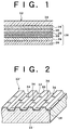
- the magneto-optical recording medium 12 usually has the form of a disk.
- a dielectric layer 16 of SiN or the like is formed on a transparent substrate 14 of glass or the like by sputtering, for example.
- the dielectric layer 16 prevents oxidation and corrosion of magnetic layers formed thereon.
- Resins such as polycarbonate, polymethylmethacrylate, and amorphous polyolefin may also be adopted as the transparent substrate 14.
- metal nitrides such as AlN, metal oxides such as SiO 2 and Al 2 O 3 , and metal sulfides such as ZnS may also be adopted as the dielectric layer 16.
- a magnetic reproducing layer 18 of GdFeCo is formed on the dielectric layer 16.
- the magnetic reproducing layer 18 has an axis of easy magnetization in a direction perpendicular to its layer surface.
- the magnetic reproducing layer 18 is transition metal-dominant, or transition metal-rich such that the magnetic moment of the transition metal is stronger than the magnetic moment of the rare earth.
- the Curie temperature of the magnetic reproducing layer 18 is about 250°C to about 300°C.
- a magnetic intermediate layer 20 of GdFeCoSi is formed on the magnetic reproducing layer 18.
- the magnetic intermediate layer 20 has an axis of easy magnetization in a plane at a room temperature.
- the axis (direction) of easy magnetization of the magnetic intermediate layer 20 changes from the in-plane to the perpendicular direction at a temperature higher than or equal to a predetermined temperature at which this layer 20 is heated by a reproducing beam.
- this predetermined temperature is preferably about 130°C or more.
- the Curie temperature of the magnetic intermediate layer 20 is about 200°C or less.
- a magnetic recording layer 22 of TbFeCo is formed on the magnetic intermediate layer 20.
- the magnetic recording layer 22 has an axis of easy magnetization in a direction perpendicular to its layer surface.
- the Curie temperature of the magnetic recording layer 22 is about 250°C to about 270°C.
- a protective layer 24 of SiN is formed on the magnetic recording layer 22.
- the protective layer 24 is provided for the purpose of preventing the entry of water or oxygen in the air or other substances such as a halogen to protect the magnetic recording layer 22.
- Metal nitrides such as SIN, AlN, metal oxides such as SiO 2 and Al 2 O 3 , and metal sulfides such as ZnS may also be adopted as the protective layer 24.
- a recording sensitivity adjusting layer (reflective layer) 26 of aluminum (Al) is formed on the protective layer 24, thus completing the magneto-optical recording medium 12.
- the magneto-optical recording medium 12 is configured by forming on the transparent substrate 14 a multilayer film 28 including the dielectric layer 16, the magnetic reproducing layer 18, the magnetic intermediate layer 20, the magnetic recording layer 22, the protective layer 24, and the recording sensitivity adjusting layer 26.
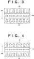
- FIG. 2 there is shown a magneto-optical recording medium 12' for land and groove recording.
- the multilayer film 28 is formed on a land/groove substrate 14' having a plurality of lands 30 and a plurality of grooves 32 alternately formed.
- the center distance (track pitch) between any adjacent ones of the lands 30 and the grooves 32 is 0.65 ⁇ m.
- the level difference between the lands 30 and the grooves 32 is 35 nm.
- the magneto-optical recording medium 12' is of a land/groove recording type, marks 34 are recorded on both the lands 30 and the grooves 32.
- Such a land/groove recording type magneto-optical recording medium having a small track pitch is of particular relevance to the present invention.
- a laser beam is directed onto the recording medium as applying a bias magnetic field Hb in the downward direction to heat the recording layer 22 to a temperature higher than or equal to the Curie temperature of the recording layer 22, thereby ordering the magnetization in the recording layer 22 in the downward direction.
- Hb bias magnetic field
- the intermediate layer 20 becomes a in-plane magnetized film, so that the reproducing layer 18 and the recording layer 22 become a magnetically uncoupled state. Accordingly, the magnetization in the reproducing layer 18 is ordered in the downward direction by the bias magnetic field Hb.
- the data double-mask reproducing method in the present invention will now be described with reference to FIGS. 5A and 5B.
- a sufficiently intense reproducing laser beam is directed onto the recording medium, there is formed in a beam spot 38 a low-temperature region where the magnetization in the reproducing layer 18 is oriented in the direction of a reproducing bias magnetic field Hr, an intermediate-temperature region where the magnetization in the recording layer 22 is transferred to the intermediate layer 20 and the reproducing layer 18 by exchange coupling, and a high-temperature region where the temperature in this region is not less than the Curie temperature Tc of the intermediate layer 20 as shown in FIGS. 5A and 5B.
- a plurality of marks 46 shown by the broken lines are formed in a track 44.
- up-spin masks 40 and 48 respectively where the direction of the magnetization in the reproducing layer 18 coincides with the direction of the bias magnetic field Hr.
- An opening 42 is formed in the intermediate-temperature region between the two up-spin masks 40 and 48.
- the recording medium is heated to a temperature not less than the Curie temperature Tc of the intermediate layer 20, so that the magnetization in the intermediate layer 20 disappears and the reproducing layer 18 and the recording layer 22 are not magnetically coupled with each other. Accordingly, the magnetization in the reproducing layer 18 at the up-spin mask 48 is oriented in the direction of the reproducing bias magnetic field Hr because the reproducing layer 18 has a small coercive force at room temperature. That is, the direction of the magnetization in the reproducing layer 18 is always upward at a temperature not less than the Curie temperature Tc of the intermediate layer 20, and the reproducing layer 18 at the up-spin mask 48 functions as a kind of mask through which no magneto-optical signal is output.
- the very small opening 42 through which data recorded in the recording layer 22 is read can be formed. Further, part of the opening 42 is formed at a central portion of the beam spot 38 where the laser intensity is higher than that at an edge portion of the beam spot 38, so that a large magneto-optical signal can be obtained.
- a land/groove substrate with the center distance (track pitch) between adjacent land and groove set to 0.65 ⁇ m was prepared.
- the level difference between the lands and the grooves of this substrate was 35 nm.
- a stationary opposed type sputtering device having a plurality of deposition chambers (sputter chambers) each capable of achieving an ultimate vacuum of 5 x 10 -5 Pa or less was prepared.
- the substrate was carried into the first chamber in which an Si target was mounted, and Ar gas and N 2 gas were introduced into the first chamber to deposit an SiN layer having a thickness of 90 nm on the substrate by reactive sputtering.
- the substrate was next moved into the second chamber in which a GdFeCo alloy target was mounted, and Ar gas was introduced into the second chamber to deposit a reproducing layer having a thickness of 50 nm by DC sputtering.
- the deposition conditions for the reproducing layer were 5.0 Pa for Ar pressure and 5.5 nm/sec for sputter rate.
- a plurality of targets for the reproducing layer were prepared by changing the compositions of Gd and Co to deposit a plurality of GdFeCo reproducing layers with different compositions of Gd and Co.
- the substrate was next moved into the third chamber in which a Gd 28 Fe 61 Co 3 Si 8 alloy target was mounted, and Ar gas was introduced into the third chamber to deposit an intermediate layer having a thickness of 40 nm. In depositing the intermediate layer, the sputter rate (power) and the Ar pressure were changed to deposit a plurality of intermediate layers.
- the substrate was next moved into the fourth chamber in which a Tb 22 Fe 61 Co 17 alloy target was mounted, and Ar gas was introduced into the fourth chamber to deposit a recording layer having a thickness of 50 nm under the deposition conditions where the sputter rate was fixed to 7 nm/sec and the Ar pressure was fixed to 7 Pa.
- the substrate was next moved into the fifth chamber in which an Si target was mounted to deposit an SiN layer having a thickness of 25 nm on the recording layer under the same deposition conditions as those in the first chamber. Further, the substrate was next moved into the sixth chamber in which an Al target was mounted to deposit an Al layer having a thickness of 20 nm. Finally, a resin protective layer was formed on the multilayer film deposited on the substrate as above by spin coating to complete the magneto-optical disk.
- a disk tester was used for evaluation and measurement on the magneto-optical disk prepared above.
- the disk tester included an optical pickup having a laser light source for outputting a laser beam having a wavelength of 650 nm and an objective lens having a numerical aperture NA of 0.55.
- the measurement was made by setting the linear velocity of the magneto-optical disk in the disk tester to 7.5 m/sec.
- a laser beam of a power suitable for recording is directed onto the medium at the same time as applying a magnetic field having a positive direction (upward direction) to form recording marks magnetized upward.
- a magnetic field having a negative direction is applied in recording data, upward magnetization may appear in some proportion if the magnitude of the magnetic field having the negative direction is small. That is, data may be recorded. Accordingly, Hwth is usually negative.
- the medium is erasable more easily, that is, the erasing magnetic field becomes smaller as Hwth becomes closer to 0.
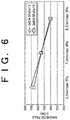
- FIG. 6 shows the results of measurement of Hwth in the case that the composition of the reproducing layer was set to Gd 24.5 Fe 62.5 Co 13 and Gd 24.5 Fe 56.5 Co 19 . That is, FIG. 6 shows the dependence of Hwth on the sputter conditions for the intermediate layer. For each composition of the reproducing layer, the sputter rate and the Ar pressure for the deposition of the intermediate layer were changed in three steps to form three kinds of intermediate layers. By using these intermediate layers, Hwth was measured.
- Hwth becomes weaker than or equal to -500 Oersteds (Oe) as a practical level by setting the sputter rate to a value greater than or equal to 7 nm/sec and the Ar pressure to a value less than or equal to 4 Pa in depositing the intermediate layer.
- This tendency is shown similarly both in the case of the Gd 24.5 Fe 62.5 Co 13 reproducing layer and in the case of the Gd 24.5 Fe 56.5 Co 19 reproducing layer. Accordingly, to sufficiently reduce the erasing magnetic field, the intermediate layer must be deposited at the Ar pressure less than or equal to 4 Pa and the sputter rate greater than or equal to 7 nm/sec.
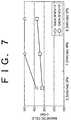
- FIG. 7 shows the dependence of the reproducing magnetic field on the sputter conditions for the intermediate layer. That is, FIG. 7 shows the results of measurement of the magnetic field Hr required for reproduction in the case that the sputter conditions for the intermediate layer were changed in three steps.
- the reproducing magnetic field Hr is a minimum magnetic field required for a sufficient reduction in bit error rate in the environment at 65°C.
- the reproducing magnetic field Hr hardly increases even though the sputter rate is increased and the Ar pressure is decreased in depositing the intermediate layer.
- the sputter rate is adjusted by changing an applied power for sputtering.
- the sputter rate of 7 nm/sec in the sputtering device used herein corresponds to an applied power of 1.25 kW.
- the reproducing magnetic field Hr remarkably increases with an increase in the sputter rate and a decrease in the Ar pressure in depositing the intermediate layer. That is, the reproducing magnetic field Hr increases under the conditions required for a reduction in Hwth shown in FIG. 6.
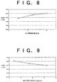
- FIG. 8 shows the dependence of Hwth on the Ar pressure for the intermediate layer in the case of the Gd 24.5 Fe 56.5 Co 19 reproducing layer.
- FIG. 9 shows the dependence of Hwth on the sputter rate for the intermediate layer in the case of the same reproducing layer as that in FIG. 8.
- Hwth can be reduced by decreasing the Ar pressure and increasing the sputter rate in depositing the intermediate layer.
- the above-mentioned results show that the magnitude of the erasing magnetic field depends on the sputter conditions for the intermediate layer and that the erasing magnetic field can be reduced to 500 Oe or less by setting the sputter rate to 7 nm/sec or more and the Ar pressure to 4 Pa or less in depositing the intermediate layer.
- the sputter rate of 7 to 10 nm/sec may be considered good in terms of the data
- the sputter rate is preferably included in such a range as to reduce the magnitude of the erasing magnetic field to 500 Oe or less.
- an Ar pressure of 2 to 4 Pa may be considered good in terms of the data
- the Ar pressure is preferably included in such a range as to reduce the erasing magnetic field to -500 Oe or weaker.
- the erasing magnetic field can be reduced with the rise in the reproducing magnetic field being suppressed, by increasing the Co composition in the GdFeCo reproducing layer to 16 at% or more.
- FIG. 10 shows the dependence of a temperature at which the magnetization in the intermediate layer changes from in-plane magnetization to perpendicular magnetization, on the sputter rate for the intermediate layer.
- FIG. 11 shows the dependence of this in-plane-to-perpendicular magnetization changing temperature on the Ar pressure for the intermediate layer.
- the in-plane-to-perpendicular magnetization changing temperature rises with an increase in the sputter rate for the intermediate layer.
- the in-plane-to-perpendicular magnetization changing temperature rises with a decrease in the Ar pressure for the intermediate layer.
- the in-plane-to-perpendicular magnetization changing temperature at which the erasing magnetic field can be reduced is preferably set to 130°C or more. Therefore, the in-plane-to-perpendicular magnetization changing temperature can be set to 130°C or more by setting the sputter rate to a value greater than 4 nm/sec and the Ar pressure to a value less than 5 Pa.
- the Curie temperature Tc of the intermediate layer is preferably set to 200°C or less. If the Curie temperature Tc of the intermediate layer is higher than 200°C, the magnetic field strength and reproducing power required for formation of the rear mask become high, causing a problem that an operation margin becomes narrow.
- FIG. 12 shows the dependence of magnetic field strength (producing a coercive force) (Hc) on temperature for the reproducing layer with a single layer, for different Gd compositions.
- Hc magnetic field strength
- the reproducing layer having a Gd composition of 25.5 at% shows a large coercive force Hc in the temperature range of room temperature to 200°C.
- Such a large coercive force Hc causes an increase in reproducing magnetic field required for formation of the rear mask.
- the magnetic field required for formation of the rear mask is 450 Oersteds (Oe), which is greater than a practical level of 350 Oersteds.
- the reproducing layer having a Gd composition of 24.8 at% its coercive force Hc is about 180 Oersteds at room temperature. This value for Hc is less than the practical level of 350 Oersteds.
- the Gd composition in the reproducing layer must be set to 25 at% or less.
- FIG. 13 shows the dependence of a reproducing magnetic field Hr on the Co composition in the reproducing layer.
- the reproducing magnetic field Hr was measured at 25°C and at 55°C.
- the Gd composition in the reproducing layer was fixed at 24.5 at%.
- the intermediate layer was deposited with the sputter rate set to 7 nm/sec and the Ar pressure set to 4 Pa.
- the reproducing magnetic field can be reduced to the practical level of 350 Oersteds (Oe) by setting the Co composition in the reproducing layer to 16 at% or more. If the Co composition is less than 16 at%, the reproducing magnetic field is greatly increased undesirably, especially at high temperatures.
- FIG. 14 shows the dependence of the carrier-to-noise ratio (C/N) on the Co composition in the reproducing layer.
- the Gd composition in the reproducing layer and the sputter conditions for the intermediate layer are similar to those in the case of FIG. 13.
- the Co composition in the reproducing layer is greater than 23 at%, the C/N undesirably becomes less than or equal to 45 dB.
- the Co composition in the reproducing layer is preferably set in the range of 16 to 23 at% providing the reproducing magnetic field of 400 Oe or less. More preferably, the Co composition in the reproducing layer is set in the range of 18 to 20 at% providing a minimum value of the reproducing magnetic field.
- FIG. 15 shows the dependence of a reproducing magnetic field Hr on the Gd composition in the reproducing layer.
- the Co composition in the reproducing layer was fixed at 19 at%. Further, the intermediate layer was deposited when the sputter rate was set to 7 nm/sec and the Ar pressure was set to 4 Pa. As apparent from FIG. 15, when the Gd composition in the reproducing layer is greater than 25 at%, the magnetic field required for formation of the rear mask is increased thereby increasing the reproducing magnetic field Hr.
- FIG. 16 shows the dependence of a C/N on the Gd composition in the reproducing layer.
- the Co composition in the reproducing layer and the sputter conditions for the intermediate layer are similar to those in the case of FIG. 15.
- the Gd composition in the reproducing layer is less than 22 at%, the C/N undesirably becomes less than or equal to 45 dB. It is concluded from the results shown in FIGS. 15 and 16 that the Gd composition in the reproducing layer is preferably set in the range of 22 to 25 at%.
- FIG. 17 shows the dependence of Hwth on the sputter rate for the intermediate layer.
- the Ar pressure for the intermediate layer was fixed at 5.0 Pa. Further, the composition of the reproducing layer was set to Gd 24.5 Fe 56.5 Co 19 .
- Hwth can be reduced to a practical level of 500 Oersteds (Oe) or weaker by setting the sputter rate for the intermediate layer to 7 nm/sec or more.
- FIG. 18 shows the dependence of a reproducing magnetic field Hr on the sputter rate for the intermediate layer.
- the composition of the reproducing layer and the Ar pressure for the intermediate layer are similar to those in the case of FIG. 17.
- the reproducing magnetic field Hr undesirably becomes greater than a practical level of 350 Oersteds (Oe). It is concluded from the results shown in FIGS. 17 and 18 that the sputter rate for the intermediate layer is preferably set in the range of 7 to 9 nm/sec.
- FIG. 19 shows the dependence of Hwth on the Ar pressure for the intermediate layer.
- the sputter rate for the intermediate layer was fixed at 5.5 nm/sec.
- the composition of the reproducing layer was set to Gd 24.5 Fe 56.5 Co 19 .
- Hwth can be reduced to -500 Oersteds (Oe) or weaker by setting the Ar pressure to 4 Pa or less in depositing the intermediate layer.
- FIG. 20 shows the dependence of a reproducing magnetic field Hr on the Ar pressure for the intermediate layer.
- the sputter rate for the intermediate layer and the composition of the reproducing layer are similar to those in the case of FIG. 19.
- the reproducing magnetic field Hr undesirably becomes greater than the practical level of 350 Oersteds (Oe). It is concluded from the results shown in FIGS. 19 and 20 that the Ar pressure for the intermediate layer is preferably set in the range of 2 to 4 Pa.
- compositions of the reproducing layer, the intermediate layer, and the recording layer are GdFeCo, GdFeCoSi, and TbFeCo, respectively.
- FIG. 21 shows the dependence of the required reproducing magnetic field on the thickness of the intermediate layer.
- FIG. 22 shows the dependence of the C/N on the thickness of the intermediate layer.
- the thickness of the intermediate layer is preferably set in the range where the reproducing magnetic field and the C/N are consistent with each other, i.e., in the range of 38 to 50 nm. More preferably, the thickness of the intermediate layer is set in the range of 43 to 48 nm where the C/N is satisfactory and the reproducing magnetic field is at a minimum.
- FIG. 23 shows the dependence of the required reproducing magnetic field on the thickness of the reproducing layer.
- FIG. 24 shows the dependence of the C/N on the thickness of the reproducing layer.
- the thickness of the reproducing layer is preferably set in the range where the reproducing magnetic field and the C/N are consistent with each other, i.e., in the range of 40 to 57 nm. More preferably, the thickness of the reproducing layer is set in the range of 45 to 50 nm.
- the material of the reproducing layer and the deposition conditions for the intermediate layer are related to each other. Further, it is also considered that the C/N and the magnetic field strength are influenced by the interaction between the reproducing layer and the intermediate layer, and it is therefore possible to improve the C/N and the magnetic field strength according to the material of the reproducing layer and the deposition conditions for the intermediate layer solely or in combination.
- Embodiments of the present invention thus provide a high-density magneto-optical recording medium which can reduce the erasing magnetic field without much increase in reproducing magnetic field, by defining the composition ranges of Gd and Co in the magnetic reproducing layer. Accordingly, a magneto-optical disk drive using this recording medium can be reduced in size and a reduction in its power consumption can be attained.
Abstract
Description
The reproduction of such small recording marks having a period shorter than the size of the beam spot may be effected by reducing the size of the beam spot. However, the size of the beam spot is limited by the wavelength λ of light output from a light source and the numerical aperture NA of an objective lens, so that the spot size cannot be sufficiently reduced.
Also in the normal magneto-optical recording medium for recording data on only the lands or only the grooves, it is important to reduce the erasing magnetic field, thereby reducing the size of the magnet in the magneto-optical disk drive and reducing the power consumption of the magneto-optical disk drive.
The reproducing magnetic field Hr is a minimum magnetic field required for a sufficient reduction in bit error rate in the environment at 65°C. As apparent from FIG. 7, in the case of the Gd24.5Fe56.5Co19 reproducing layer, the reproducing magnetic field Hr hardly increases even though the sputter rate is increased and the Ar pressure is decreased in depositing the intermediate layer.
However, if the Gd composition is greater than 25 at%, the magnetic field required for formation of the rear mask becomes so large that it exceeds the magnitude of the magnetic field that can be practically generated in a magneto-optical disk drive. Therefore, the Gd composition in the reproducing layer must be set to 25 at% or less.
It is concluded from the results shown in FIGS. 17 and 18 that the sputter rate for the intermediate layer is preferably set in the range of 7 to 9 nm/sec.
The composition of the reproducing layer was set to Gd24.5Fe56.5Co19. As apparent from FIG. 19, Hwth can be reduced to -500 Oersteds (Oe) or weaker by setting the Ar pressure to 4 Pa or less in depositing the intermediate layer.
Claims (10)
- A magneto-optical recording medium (12) comprising:a magnetic reproducing layer (18) having an axis of easy magnetization in a direction perpendicular to its layer surface;a magnetic intermediate layer (20) formed on said magnetic reproducing layer (18) and having an axis of easy magnetization in a plane at room temperature; anda magnetic recording layer (22) formed on said magnetic intermediate layer (20) and having an axis of easy magnetization in a direction perpendicular to its layer surface;
wherein said magnetic reproducing layer (18) has a composition of GdxFeCoy where 22 at% ≤ x ≤ 25 at% and 16 at% ≤ y ≤ 23 at%. - A magneto-optical recording medium (12) according to claim 1, wherein said magnetic reproducing layer (18) is formed from a rare earth-transition metal amorphous alloy film, and is transition metal-dominant such that the magnetic moment of the transition metal is dominating over the magnetic moment of the rare earth.
- A magneto-optical recording medium (12) according to claims 1 or 2, wherein said magnetic intermediate layer (20) has a Curie temperature of 200°C or less, and a temperature at which the magnetization in said magnetic intermediate layer (20) in the case of a single layer changes to perpendicular magnetization is 130°C or more.
- A magneto-optical recording medium (12) according to any of claims 1 to 3, further comprising:
a transparent substrate (14) having a plurality of lands (30) and a plurality of grooves (32) alternately formed;
wherein said magnetic reproducing layer (18) is formed on said transparent substrate. - A manufacturing method for a magneto-optical recording medium (12) comprising a magnetic reproducing layer (18) having an axis of easy magnetization in a direction perpendicular to its layer surface; a magnetic intermediate layer (20) formed on said magnetic reproducing layer (18) and having an axis of easy magnetization in a plane at room temperature; and a magnetic recording layer (22) formed on said magnetic intermediate layer (20) and having an axis of easy magnetization in a direction perpendicular to its layer surface; said magnetic reproducing layer (18) having a composition of GdxFeCoy where 22 at% ≤ x ≤ 25 at% and 16 at% ≤ y ≤ 23 at%, said manufacturing method comprising the step of:
depositing said magnetic intermediate layer (20) by sputtering at a sputter rate of 7 nm/sec to 9 nm/sec under an Ar gas pressure of 2 Pa to 4 Pa. - A magneto-optical recording medium (12) comprising:a GdFeCo reproducing layer (18) having an axis of easy magnetization in a direction perpendicular to its layer surface, said reproducing layer (18) having a thickness of 40 to 57 nm;a GdFeCoSi intermediate layer (20) formed on said reproducing layer (18) and having an axis of easy magnetization in a plane at a room temperature, said intermediate layer (20) having a thickness of 38 to 50 nm; anda TbFeCo recording layer (22) formed on said intermediate layer (20) and having an axis of easy magnetization in a direction perpendicular to its layer surface.
- A magneto-optical recording medium (12) according to claim 6, wherein said reproducing layer (18) has a composition of GdxFeCoy where 22 at% ≤ x ≤ 25 at% and 16 at% ≤ y ≤ 23 at%.
- A magneto-optical recording medium (12) according to claim 6 or 7, wherein said reproducing layer (18) has a thickness of 45 to 50 nm, and said intermediate layer (20) has a thickness of 43 to 48 nm.
- A magneto-optical recording medium (12) according to any of claims 6 to 8, wherein said intermediate layer (20) has a Curie temperature of 200°C or less, and a temperature at which the magnetization in said intermediate layer in the case of a single layer changes to perpendicular magnetization is 130°C or more.
- A manufacturing method for a magneto-optical recording medium (12) comprising a GdFeCo reproducing layer (18) having an axis of easy magnetization in a direction perpendicular to its layer surface, said reproducing layer (18) having a thickness of 40 to 57 nm; a GdFeCoSi intermediate layer (20) formed on said reproducing layer (18) and having an axis of easy magnetization in a plane at a room temperature, said intermediate layer (20) having a thickness of 38 to 50 nm; and a TbFeCo recording layer formed on said intermediate layer (20) and having an axis of easy magnetization in a direction perpendicular to its layer surface; said reproducing layer (18) having a composition of GdxFeCoy where 22 at% ≤ x ≤ 25 at% and 16 at% ≤ y ≤ 23 at%, said manufacturing method comprising the step of:
depositing said intermediate layer (20) by sputtering at a sputter rate of 7 nm/sec to 9 nm/sec under an Ar gas pressure of 2 Pa to 4 Pa.
Applications Claiming Priority (2)
| Application Number | Priority Date | Filing Date | Title |
|---|---|---|---|
| JP2000151717A JP2001331985A (en) | 2000-05-23 | 2000-05-23 | Magneto-optical recording medium and method of manufacturing the same |
| JP2000151717 | 2000-05-23 |
Publications (2)
| Publication Number | Publication Date |
|---|---|
| EP1158508A2 true EP1158508A2 (en) | 2001-11-28 |
| EP1158508A3 EP1158508A3 (en) | 2005-09-14 |
Family
ID=18657227
Family Applications (1)
| Application Number | Title | Priority Date | Filing Date |
|---|---|---|---|
| EP00311787A Withdrawn EP1158508A3 (en) | 2000-05-23 | 2000-12-29 | Magneto-optical recording medium and manufacturing method therefor |
Country Status (3)
| Country | Link |
|---|---|
| US (1) | US6649285B2 (en) |
| EP (1) | EP1158508A3 (en) |
| JP (1) | JP2001331985A (en) |
Families Citing this family (3)
| Publication number | Priority date | Publication date | Assignee | Title |
|---|---|---|---|---|
| JP2003016704A (en) * | 2001-06-29 | 2003-01-17 | Sony Corp | Magneto-optical recording medium and method of manufacturing the same |
| JP4332832B2 (en) * | 2001-07-06 | 2009-09-16 | 富士電機デバイステクノロジー株式会社 | Perpendicular magnetic recording medium and manufacturing method thereof |
| US20050188397A1 (en) * | 2002-12-24 | 2005-08-25 | Fujitsu Limited | Magneto-optical recording medium and magneto-optical recording medium substrate manufacturing method |
Family Cites Families (11)
| Publication number | Priority date | Publication date | Assignee | Title |
|---|---|---|---|---|
| JP3092363B2 (en) * | 1992-12-01 | 2000-09-25 | 松下電器産業株式会社 | Magneto-optical recording medium |
| JP3088619B2 (en) * | 1994-01-17 | 2000-09-18 | 富士通株式会社 | Magneto-optical recording medium and method of reproducing information recorded on the medium |
| JPH09212927A (en) * | 1996-02-09 | 1997-08-15 | Hitachi Ltd | Magneto-optical recording medium and recording / reproducing method using the same |
| KR20000022390A (en) * | 1996-07-12 | 2000-04-25 | 다카노 야스아키 | Mgneto-optical recording medium, its reproducing method and reproducer |
| JP3245704B2 (en) | 1996-10-18 | 2002-01-15 | 富士通株式会社 | Magneto-optical recording medium and method of manufacturing the same |
| JPH10188379A (en) | 1996-10-24 | 1998-07-21 | Nikon Corp | Magneto-optical recording medium and reproducing method thereof |
| US6017620A (en) * | 1997-04-10 | 2000-01-25 | Tdk Corporation | Magneto-optical recording medium |
| JPH10293949A (en) | 1997-04-18 | 1998-11-04 | Nikon Corp | Magneto-optical recording medium |
| JPH10312594A (en) * | 1997-05-12 | 1998-11-24 | Tdk Corp | Magnetooptic recording medium |
| JP2000200448A (en) * | 1998-10-30 | 2000-07-18 | Fujitsu Ltd | Magneto-optical recording medium and method of manufacturing magneto-optical recording medium |
| JP2002050090A (en) * | 2000-05-25 | 2002-02-15 | Fujitsu Ltd | Optical recording medium |
-
2000
- 2000-05-23 JP JP2000151717A patent/JP2001331985A/en active Pending
- 2000-12-20 US US09/745,113 patent/US6649285B2/en not_active Expired - Fee Related
- 2000-12-29 EP EP00311787A patent/EP1158508A3/en not_active Withdrawn
Also Published As
| Publication number | Publication date |
|---|---|
| EP1158508A3 (en) | 2005-09-14 |
| US20020022153A1 (en) | 2002-02-21 |
| US6649285B2 (en) | 2003-11-18 |
| JP2001331985A (en) | 2001-11-30 |
Similar Documents
| Publication | Publication Date | Title |
|---|---|---|
| US6177175B1 (en) | Magneto-optical medium utilizing domain wall displacement | |
| US5862105A (en) | Information recording method capable of verifying recorded information simultaneously with recording, and magneto-optical recording medium used in the method | |
| JP2809991B2 (en) | Magneto-optical recording medium and method of reproducing information recorded on the medium | |
| US5754500A (en) | Magneto-optical recording medium and method of reading the same | |
| US6570826B2 (en) | Optical recording medium allowing high-density recording and reproduction of information | |
| US6826131B2 (en) | Magneto-optical recording medium having multiple magnetic layers | |
| EP0997894B1 (en) | Magneto-optical recording medium and method of manufacturing magneto-optical recording medium | |
| US6180268B1 (en) | Magneto-optical recording medium | |
| US6649285B2 (en) | Magneto-optical recording medium and manufacturing method therefor | |
| EP0668585B1 (en) | Information recording method and system using a magneto-optical medium | |
| JPH08180482A (en) | Magneto-optical recording medium and information reproducing method using the medium | |
| US6808823B2 (en) | Magneto-optical recording medium and manufacturing method therefor | |
| US6767656B2 (en) | Magneto-optical recording medium and method of reproducing the same | |
| US5831944A (en) | Magnetooptical recording medium and method for reproducing information from a magnetooptical recording medium having three layers | |
| US7173884B2 (en) | Magnetooptic recording medium and its manufacturing method | |
| JP3592399B2 (en) | Magneto-optical recording medium | |
| US20050028183A1 (en) | Magneto-optical recording medium having in-plane magnetizing layer | |
| JPH08106662A (en) | Magneto-optical recording medium | |
| EP0595639A2 (en) | Magnetooptical recording medium and method of recording data thereon | |
| JPH0896428A (en) | Magneto-optical recording medium | |
| JPH0817080A (en) | Magneto-optical recording / reproducing method and magneto-optical recording medium used therefor | |
| EP1045381A2 (en) | Magneto-optical disk | |
| EP1524658A1 (en) | Magneto-optical recording medium and magneto-optical storage device | |
| JP2003077192A (en) | Magneto-optical recording medium | |
| JPH08315435A (en) | Magneto-optical recording medium |
Legal Events
| Date | Code | Title | Description |
|---|---|---|---|
| PUAI | Public reference made under article 153(3) epc to a published international application that has entered the european phase |
Free format text: ORIGINAL CODE: 0009012 |
|
| AK | Designated contracting states |
Kind code of ref document: A2 Designated state(s): AT BE CH CY DE DK ES FI FR GB GR IE IT LI LU MC NL PT SE TR |
|
| AX | Request for extension of the european patent |
Free format text: AL;LT;LV;MK;RO;SI |
|
| PUAL | Search report despatched |
Free format text: ORIGINAL CODE: 0009013 |
|
| AK | Designated contracting states |
Kind code of ref document: A3 Designated state(s): AT BE CH CY DE DK ES FI FR GB GR IE IT LI LU MC NL PT SE TR |
|
| AX | Request for extension of the european patent |
Extension state: AL LT LV MK RO SI |
|
| AKX | Designation fees paid | ||
| REG | Reference to a national code |
Ref country code: DE Ref legal event code: 8566 |
|
| STAA | Information on the status of an ep patent application or granted ep patent |
Free format text: STATUS: THE APPLICATION IS DEEMED TO BE WITHDRAWN |
|
| 18D | Application deemed to be withdrawn |
Effective date: 20060315 |