EP1158487B1 - Microphone support in an active noise attenuation system - Google Patents
Microphone support in an active noise attenuation system Download PDFInfo
- Publication number
- EP1158487B1 EP1158487B1 EP01201623A EP01201623A EP1158487B1 EP 1158487 B1 EP1158487 B1 EP 1158487B1 EP 01201623 A EP01201623 A EP 01201623A EP 01201623 A EP01201623 A EP 01201623A EP 1158487 B1 EP1158487 B1 EP 1158487B1
- Authority
- EP
- European Patent Office
- Prior art keywords
- air induction
- microphone
- speaker
- rigid support
- mouth
- Prior art date
- Legal status (The legal status is an assumption and is not a legal conclusion. Google has not performed a legal analysis and makes no representation as to the accuracy of the status listed.)
- Expired - Lifetime
Links
Images



Classifications
-
- G—PHYSICS
- G10—MUSICAL INSTRUMENTS; ACOUSTICS
- G10K—SOUND-PRODUCING DEVICES; METHODS OR DEVICES FOR PROTECTING AGAINST, OR FOR DAMPING, NOISE OR OTHER ACOUSTIC WAVES IN GENERAL; ACOUSTICS NOT OTHERWISE PROVIDED FOR
- G10K11/00—Methods or devices for transmitting, conducting or directing sound in general; Methods or devices for protecting against, or for damping, noise or other acoustic waves in general
- G10K11/16—Methods or devices for protecting against, or for damping, noise or other acoustic waves in general
- G10K11/175—Methods or devices for protecting against, or for damping, noise or other acoustic waves in general using interference effects; Masking sound
- G10K11/178—Methods or devices for protecting against, or for damping, noise or other acoustic waves in general using interference effects; Masking sound by electro-acoustically regenerating the original acoustic waves in anti-phase
- G10K11/1785—Methods, e.g. algorithms; Devices
- G10K11/17857—Geometric disposition, e.g. placement of microphones
-
- G—PHYSICS
- G10—MUSICAL INSTRUMENTS; ACOUSTICS
- G10K—SOUND-PRODUCING DEVICES; METHODS OR DEVICES FOR PROTECTING AGAINST, OR FOR DAMPING, NOISE OR OTHER ACOUSTIC WAVES IN GENERAL; ACOUSTICS NOT OTHERWISE PROVIDED FOR
- G10K11/00—Methods or devices for transmitting, conducting or directing sound in general; Methods or devices for protecting against, or for damping, noise or other acoustic waves in general
- G10K11/16—Methods or devices for protecting against, or for damping, noise or other acoustic waves in general
- G10K11/175—Methods or devices for protecting against, or for damping, noise or other acoustic waves in general using interference effects; Masking sound
- G10K11/178—Methods or devices for protecting against, or for damping, noise or other acoustic waves in general using interference effects; Masking sound by electro-acoustically regenerating the original acoustic waves in anti-phase
- G10K11/1787—General system configurations
- G10K11/17879—General system configurations using both a reference signal and an error signal
- G10K11/17883—General system configurations using both a reference signal and an error signal the reference signal being derived from a machine operating condition, e.g. engine RPM or vehicle speed
Definitions
- This invention relates to an active method and system for controlling automotive induction noise.
- Active systems use a speaker to create a canceling sound that attenuates engine noise.
- the sound created is out of phase with the engine noise and combines with this noise to result in its reduction.
- this sound is generated in proximity to the mouth of the air induction system.
- a control unit such as a digital signal processor, obtains data from the vehicle engine, creates a predictive model of engine noise, and thereby generates the appropriate cancellation signal based on the results of this model. This signal is then transmitted to the speaker, which transforms this signal into a canceling sound. Because the control unit may not perfectly model engine noise, an error microphone is placed in proximity to the mouth of the air induction system to determine if engine noise need be further attenuated.
- the error microphone is placed on the fender of the vehicle while the speaker of the system is generally attached to the air induction system.
- road conditions may cause the error microphone to vibrate significantly.
- the speaker and error microphone may vibrate at different rates.
- the noise attenuation system may function less than optimally due to the relative movement between the speaker and error microphone.
- the noise attenuation system may even generate a howling sound or other undesirable noise as a consequence of this problem.
- Foam is not durable, serving as a less than optimal support for an error microphone over the operational life of the vehicle. In particular, foam is prone to damage caused by weathering, road salt, road wear, and other environmental conditions, which are encountered during the operation of a vehicle.
- the foam support covers the entire speaker face.
- the foam support creates acoustic interference for the noise attenuation system under certain frequencies and even restricts airflow around the air intake.
- the foam support is mounted to the speaker face, it may interfere with the speaker's operation.
- EPO 0,884,471 describes an active noise attenuation system in which a microphone is mounted within an open cell foam fairing piece.
- US 5,336,856 describes an active noise cancellation system used to quiet engine exhaust noise.
- an air induction system comprising: an air induction body having a mouth; a speaker operatively connected to said air induction body, wherein the speaker has a face; a microphone operatively connected to said air induction body; and a control unit in communication with said speaker and said microphone, characterised in that the microphone is connected to the air induction body by a rigid support, spaced a pre-determined distance from said face, wherein said predetermined distance relates to the location of the sound field emitted by said speaker and wherein said rigid support comprises a plurality of legs radially extending from said microphone and operatively connecting said microphone to said air induction body.
- a rigid support is used to connect the microphone to the air induction body, locking the microphone in place and providing a durable connection to the air induction body.
- the rigid support may be made of plastic.
- the microphone may be operatively connected to the mouth of the air induction body.
- a screen may span at least a portion of the mouth of the air induction system. This screen, which may be nylon, serves to protect the air induction system from large objects that may find their way in the path of the moving vehicle.
- the rigid support is designed to be as acoustically transparent as is reasonably possible.
- the design may also be vented by one or a plurality of openings that may skirt the mouth of the air induction system.
- FIG. 1 illustrates an embodiment of the invention. Shown are air induction body 10 with mouth 14. Speaker 18 with face 20 is operatively connected to air induction body 10 by a support as known. Microphone 22, an error microphone, is operatively connected by rigid support 26 to air induction body 10 instead of to a fender of a vehicle.
- the material used to construct rigid support 26 is not pliable like foam, allowing rigid support 26 to firmly lock microphone 22 into position. Plastic is one such material that may be used for rigid support 26. Rigid, as used in this application, should be interpreted relative to the non-rigid open cell foam of the prior art.
- Both microphone 22 and speaker 18 are in communication with control unit 30. Also in communication with control unit 30 are engine speed sensor 34 and throttle position sensor 38. These sensors 34 and 38 provide information on engine speed and position of throttle blade as taught by the prior art.
- engine noise 16A and 16B emanate from vehicle engine 12 through air induction 10 out of mouth 14.
- Speaker 18 generates sound field 17 with sound out of phase with engine noise 16A and 16B.
- a novel feature of the invention concerns the spacing away of support 26 from speaker 18 while still operatively connecting microphone 22 to air induction body 10 through support 26.
- this embodiment of the invention involves microphone 22 operatively connected to air induction body 10 by support 26, which is spaced a predetermined distance from face 20 of speaker 18 wherein the predetermined distance relates to the location of sound field 17 emitted by speaker 18. It is preferable to locate microphone 22 off the center of sound field 17 to ensure complete reception of sound.
- Support 26 is also preferably designed to place microphone 22 off center of sound field 17 as shown.
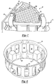
- FIG. 2 illustrates a perspective view of a portion of the embodiment pictured in Figure 1.
- Figure 2 shows microphone 22 set in rigid support 26.
- Rigid support 26 is operatively connected to mouth 14, which itself is part of air induction body 10.
- speaker 18 is disposed in mouth 14.
- Rigid support 26 extends over only a portion of face 20 and may comprise at least one leg such as 28A, 28B, 28C, and 28D operatively connecting microphone 22 to air induction body 10.
- An encircling ring 29 extends circumferentially to connect legs 28A-28D.
- the design of rigid support 26 is thus designed to be relatively acoustically transparent to avoid interference with low frequency sound waves. Acoustic transparency is accomplished by ensuring that rigid support 26 does not itself create a pressure barrier during operation of the system.
- FIG. 3 shows a side view of the embodiment of Figures 1 and 2. Microphone 22 is more clearly shown locked in rigid support 26. Rigid support 26 is operatively connected to mouth 14.
- Figure 4 shows a front view of the embodiment of Figures 1-3.
- Rigid support 26 and mouth 14 are shown.
- Figure 4 also illustrates a plurality of legs 28A, 28B, 28C, and 28D radially extending from the microphone and operatively connecting the microphone to air induction body 10, here at mouth 14.
- Rigid support 26 is also vented by at least one opening 32. This design is relatively acoustically transparent at low frequencies and creates only negligible air restriction around mouth 14. Not pictured is microphone 22.
- Figure 5 shows a side view of the embodiment of Figures 1-4. Rigid support 26, mouth 14, and microphone 22. Speaker 18 is hidden in this perspective.
- Figure 6 shows a side view of the embodiment of Figure 5 with speaker 18 shown. Also illustrated are air induction body 10, mouth 14, microphone 22, and a portion of rigid support 26. As known, air flows into air induction body 10 through inlets 42A and 42B.
- Figure 7 shows another side view of the embodiment of Figure 5 with another feature. Mouth 14, rigid support 26, and microphone 22 are illustrated. Also shown is conductor 46, which is operatively connected to rigid support 26 through microphone 22. Conductor 46 may be a flex cable. Moreover, screen 50, provides protection of the air induction system from debris that may otherwise enter system. Screen 50 may be a nylon mesh. Note that the legs 28A-28D and ring 29 preferably provide said positioning and draping for screen. However, other embodiments may use the screen.
- FIG 8 shows a perspective view of another embodiment of the invention. Shown is another rigid support 54. Microphone 56 is also shown. Here, support 54 is vented by a plurality of openings 64 skirting mouth 60. These openings 64 serve to prevent the creation of a pressure barrier around mouth 60 of air induction body 10. In this way, rigid support 54 becomes acoustically transparent. Mounts, such as mount 62, are also shown. Mount 62 is used to quickly connect rigid support 54 to air induction body 10. A side view of this embodiment is shown in Figure 9. Here, rigid support 54 is operatively connected to mouth 58.
- Figure 10 shows a front view of the embodiment, illustrating the location of microphone 56. Notably, microphone 56 is molded as part of rigid support 54 and located off center of rigid support 54. In this way, microphone 56 is in optimal position to receive sound field 17 (as seen in Figure 1).
Landscapes
- Physics & Mathematics (AREA)
- Engineering & Computer Science (AREA)
- Acoustics & Sound (AREA)
- Multimedia (AREA)
- Fittings On The Vehicle Exterior For Carrying Loads, And Devices For Holding Or Mounting Articles (AREA)
- Soundproofing, Sound Blocking, And Sound Damping (AREA)
- Exhaust Silencers (AREA)
- Circuit For Audible Band Transducer (AREA)
Description
- This invention relates to an active method and system for controlling automotive induction noise.
- Manufacturers have employed active and passive methods to reduce engine noise within the passenger compartment. Such noise frequently emanates from the engine, travels through the air induction system and emanates out of the mouth of the air intake into the passenger compartment. Efforts have been made to reduce the amount of engine noise traveling through the air induction system. These efforts include the use of both passive devices such as expansion chambers and Helmholtz resonators and active devices involving anti-noise generators.
- Active systems use a speaker to create a canceling sound that attenuates engine noise. The sound created is out of phase with the engine noise and combines with this noise to result in its reduction. Generally, this sound is generated in proximity to the mouth of the air induction system. In one such system, a control unit, such as a digital signal processor, obtains data from the vehicle engine, creates a predictive model of engine noise, and thereby generates the appropriate cancellation signal based on the results of this model. This signal is then transmitted to the speaker, which transforms this signal into a canceling sound. Because the control unit may not perfectly model engine noise, an error microphone is placed in proximity to the mouth of the air induction system to determine if engine noise need be further attenuated.
- Typically, the error microphone is placed on the fender of the vehicle while the speaker of the system is generally attached to the air induction system. During vehicle operation, road conditions may cause the error microphone to vibrate significantly. Because the speaker is located on the air induction system, the speaker and error microphone may vibrate at different rates. As a consequence, the noise attenuation system may function less than optimally due to the relative movement between the speaker and error microphone. The noise attenuation system may even generate a howling sound or other undesirable noise as a consequence of this problem.
- One proposed solution is the attachment of the error microphone to a piece of open cell foam, which is then connected to the housing of the speaker. The foam is mounted on the speaker. While foam permits the error microphone to vibrate with the speaker, it has several drawbacks. Foam is not durable, serving as a less than optimal support for an error microphone over the operational life of the vehicle. In particular, foam is prone to damage caused by weathering, road salt, road wear, and other environmental conditions, which are encountered during the operation of a vehicle.
- Moreover, the foam support covers the entire speaker face. As a consequence, the foam support creates acoustic interference for the noise attenuation system under certain frequencies and even restricts airflow around the air intake. Also, because the foam support is mounted to the speaker face, it may interfere with the speaker's operation.
- EPO 0,884,471 describes an active noise attenuation system in which a microphone is mounted within an open cell foam fairing piece.
- US 5,336,856 describes an active noise cancellation system used to quiet engine exhaust noise.
- A need therefore exists to provide for a support that permits the error microphone to vibrate with the speaker of the noise attenuation system without the drawbacks of a foam microphone support.
- According to the invention there is provided an air induction system comprising: an air induction body having a mouth; a speaker operatively connected to said air induction body, wherein the speaker has a face; a microphone operatively connected to said air induction body; and a control unit in communication with said speaker and said microphone, characterised in that the microphone is connected to the air induction body by a rigid support, spaced a pre-determined distance from said face, wherein said predetermined distance relates to the location of the sound field emitted by said speaker and wherein said rigid support comprises a plurality of legs radially extending from said microphone and operatively connecting said microphone to said air induction body.
- In embodiments of the invention, rather than a foam support, a rigid support is used to connect the microphone to the air induction body, locking the microphone in place and providing a durable connection to the air induction body. The rigid support may be made of plastic.
- The microphone may be operatively connected to the mouth of the air induction body. A screen may span at least a portion of the mouth of the air induction system. This screen, which may be nylon, serves to protect the air induction system from large objects that may find their way in the path of the moving vehicle.
- The rigid support is designed to be as acoustically transparent as is reasonably possible. The design may also be vented by one or a plurality of openings that may skirt the mouth of the air induction system.
- The various features and advantages of this invention will become apparent to those skilled in the art from the following detailed description of the currently preferred embodiment. The drawings that accompany the detailed description can be briefly described as follows:
- Figure 1 shows a schematic view of an embodiment of the invention, including speaker, microphone, and support.
- Figure 2 shows a perspective view of the embodiment of Figure 1, including speaker, microphone, support, and air induction body and mouth.
- Figure 3 shows a side view of the embodiment of Figures 1-2, illustrating speaker, microphone, support, and mouth.
- Figure 4 shows a front view of the support of the embodiment of Figures 1-3 without microphone.
- Figure 5 shows a side view of the embodiment of Figures 1-4.
- Figure 6 shows an internal view of the embodiment of Figures 1-5, including speaker and air inlet.
- Figure 7 shows the embodiment of Figures 1-6 with a screen.
- Figure 8 shows a perspective view of another embodiment of the invention.
- Figure 9 shows a side view of an embodiment of the invention, including microphone.
- Figure 10 shows a front view of the embodiment of Figure 9, including microphone.
- Figure 1 illustrates an embodiment of the invention. Shown are
air induction body 10 withmouth 14.Speaker 18 withface 20 is operatively connected toair induction body 10 by a support as known. Microphone 22, an error microphone, is operatively connected byrigid support 26 toair induction body 10 instead of to a fender of a vehicle. The material used to constructrigid support 26 is not pliable like foam, allowingrigid support 26 to firmly lockmicrophone 22 into position. Plastic is one such material that may be used forrigid support 26. Rigid, as used in this application, should be interpreted relative to the non-rigid open cell foam of the prior art. Bothmicrophone 22 andspeaker 18 are in communication withcontrol unit 30. Also in communication withcontrol unit 30 are engine speed sensor 34 andthrottle position sensor 38. Thesesensors 34 and 38 provide information on engine speed and position of throttle blade as taught by the prior art. - As known, engine noise 16A and 16B emanate from
vehicle engine 12 throughair induction 10 out ofmouth 14.Speaker 18 generatessound field 17 with sound out of phase with engine noise 16A and 16B. While it is known to placemicrophone 22 aboutsound field 17, a novel feature of the invention concerns the spacing away ofsupport 26 fromspeaker 18 while still operatively connectingmicrophone 22 toair induction body 10 throughsupport 26. Hence, this embodiment of the invention involvesmicrophone 22 operatively connected toair induction body 10 bysupport 26, which is spaced a predetermined distance fromface 20 ofspeaker 18 wherein the predetermined distance relates to the location ofsound field 17 emitted byspeaker 18. It is preferable to locatemicrophone 22 off the center ofsound field 17 to ensure complete reception of sound.Support 26 is also preferably designed to placemicrophone 22 off center ofsound field 17 as shown. - Figure 2 illustrates a perspective view of a portion of the embodiment pictured in Figure 1. Figure 2 shows
microphone 22 set inrigid support 26.Rigid support 26 is operatively connected tomouth 14, which itself is part ofair induction body 10. As known in the art,speaker 18 is disposed inmouth 14.Rigid support 26 extends over only a portion offace 20 and may comprise at least one leg such as 28A, 28B, 28C, and 28D operatively connectingmicrophone 22 toair induction body 10. Anencircling ring 29 extends circumferentially to connect legs 28A-28D. The design ofrigid support 26 is thus designed to be relatively acoustically transparent to avoid interference with low frequency sound waves. Acoustic transparency is accomplished by ensuring thatrigid support 26 does not itself create a pressure barrier during operation of the system. - Figure 3 shows a side view of the embodiment of Figures 1 and 2.
Microphone 22 is more clearly shown locked inrigid support 26.Rigid support 26 is operatively connected tomouth 14. - Figure 4 shows a front view of the embodiment of Figures 1-3.
Rigid support 26 andmouth 14 are shown. Figure 4 also illustrates a plurality of legs 28A, 28B, 28C, and 28D radially extending from the microphone and operatively connecting the microphone toair induction body 10, here atmouth 14.Rigid support 26 is also vented by at least oneopening 32. This design is relatively acoustically transparent at low frequencies and creates only negligible air restriction aroundmouth 14. Not pictured ismicrophone 22. - Figure 5 shows a side view of the embodiment of Figures 1-4.
Rigid support 26,mouth 14, andmicrophone 22.Speaker 18 is hidden in this perspective. - Figure 6 shows a side view of the embodiment of Figure 5 with
speaker 18 shown. Also illustrated areair induction body 10,mouth 14,microphone 22, and a portion ofrigid support 26. As known, air flows intoair induction body 10 through inlets 42A and 42B. - Figure 7 shows another side view of the embodiment of Figure 5 with another feature.
Mouth 14,rigid support 26, andmicrophone 22 are illustrated. Also shown isconductor 46, which is operatively connected torigid support 26 throughmicrophone 22.Conductor 46 may be a flex cable. Moreover,screen 50, provides protection of the air induction system from debris that may otherwise enter system.Screen 50 may be a nylon mesh. Note that the legs 28A-28D andring 29 preferably provide said positioning and draping for screen. However, other embodiments may use the screen. - Figure 8 shows a perspective view of another embodiment of the invention. Shown is another
rigid support 54.Microphone 56 is also shown. Here,support 54 is vented by a plurality ofopenings 64 skirtingmouth 60. Theseopenings 64 serve to prevent the creation of a pressure barrier aroundmouth 60 ofair induction body 10. In this way,rigid support 54 becomes acoustically transparent. Mounts, such asmount 62, are also shown.Mount 62 is used to quickly connectrigid support 54 toair induction body 10. A side view of this embodiment is shown in Figure 9. Here,rigid support 54 is operatively connected tomouth 58.
Figure 10 shows a front view of the embodiment, illustrating the location ofmicrophone 56. Notably,microphone 56 is molded as part ofrigid support 54 and located off center ofrigid support 54. In this way,microphone 56 is in optimal position to receive sound field 17 (as seen in Figure 1).
Claims (9)
- An air induction system comprising:an air induction body (10) having a mouth (14);a speaker (18) operatively connected to said air induction body (10), wherein the speaker has a face (20);a microphone (22, 56) operatively connected to said air induction body (10); anda control unit (30) in communication with said speaker (18) and said microphone (22, 56),wherein the microphone (22, 56) is connected to the air induction body (10) by a rigid support (26, 54), spaced a predetermined distance from said face (20);
wherein said predetermined distance relates to the location of the sound field emitted by said speaker (18),
characterised in that said rigid support (26) comprises a plurality of legs (28A-28D) radially extending from said microphone (22) and operatively connecting said microphone (22) to said air induction body (10). - The air induction system of claim 1, wherein said microphone (22, 56) is operatively connected to said mouth (14).
- The air induction system of claim 1, wherein a flex cable (46) communicates with said speaker (18).
- The air induction system of claim 1, wherein said rigid support (26, 54) is plastic.
- The air induction system of claim 1, including a screen spanning at least a portion of said mouth (14).
- The air induction system of claim 1, wherein a circumferentially extending ring (29) connects said plurality of legs (28A-28D).
- The air induction system of claim 6, wherein a screen is draped on said legs (28A-28D) and said ring (29).
- An air induction system according to any preceding claim, wherein the speaker (18) has a face (20); and the rigid support (26) extends over only a portion of said face (20).
- The air induction system of any preceding claim, wherein said support (26, 54) is designed to be acoustically transparent.
Applications Claiming Priority (8)
| Application Number | Priority Date | Filing Date | Title |
|---|---|---|---|
| US20378000P | 2000-05-12 | 2000-05-12 | |
| US20377700P | 2000-05-12 | 2000-05-12 | |
| US20377600P | 2000-05-12 | 2000-05-12 | |
| US20377900P | 2000-05-12 | 2000-05-12 | |
| US203780P | 2000-05-12 | ||
| US203779P | 2000-05-12 | ||
| US203777P | 2000-05-12 | ||
| US203776P | 2000-05-12 |
Publications (3)
| Publication Number | Publication Date |
|---|---|
| EP1158487A2 EP1158487A2 (en) | 2001-11-28 |
| EP1158487A3 EP1158487A3 (en) | 2003-03-26 |
| EP1158487B1 true EP1158487B1 (en) | 2006-06-14 |
Family
ID=27498510
Family Applications (1)
| Application Number | Title | Priority Date | Filing Date |
|---|---|---|---|
| EP01201623A Expired - Lifetime EP1158487B1 (en) | 2000-05-12 | 2001-05-04 | Microphone support in an active noise attenuation system |
Country Status (3)
| Country | Link |
|---|---|
| US (1) | US20010036282A1 (en) |
| EP (1) | EP1158487B1 (en) |
| DE (1) | DE60120558T2 (en) |
Families Citing this family (2)
| Publication number | Priority date | Publication date | Assignee | Title |
|---|---|---|---|---|
| DE10146121B4 (en) * | 2001-09-19 | 2004-01-08 | Ford Global Technologies, Inc., Dearborn | Method for determining the structure-borne and airborne noise component of an engine noise |
| EP2797075B1 (en) * | 2013-04-26 | 2018-09-12 | Eberspächer Exhaust Technology GmbH & Co. KG | System for influencing exhaust noise, engine noise and/or intake noise |
Family Cites Families (23)
| Publication number | Priority date | Publication date | Assignee | Title |
|---|---|---|---|---|
| US3936606A (en) * | 1971-12-07 | 1976-02-03 | Wanke Ronald L | Acoustic abatement method and apparatus |
| GB2076049B (en) * | 1980-05-17 | 1983-10-26 | Rolls Royce | Variable acoustic impedance lining |
| US4665549A (en) * | 1985-12-18 | 1987-05-12 | Nelson Industries Inc. | Hybrid active silencer |
| GB8603678D0 (en) * | 1986-02-14 | 1986-03-19 | Gen Electric Co Plc | Active noise control |
| JPH01245795A (en) * | 1988-03-28 | 1989-09-29 | Daikin Ind Ltd | Electronic silencer |
| US5446790A (en) * | 1989-11-24 | 1995-08-29 | Nippondenso Co., Ltd. | Intake sound control apparatus |
| US5457749A (en) * | 1990-04-09 | 1995-10-10 | Noise Cancellation Technologies, Inc. | Electronic muffler |
| US5229556A (en) * | 1990-04-25 | 1993-07-20 | Ford Motor Company | Internal ported band pass enclosure for sound cancellation |
| US5319165A (en) * | 1990-04-25 | 1994-06-07 | Ford Motor Company | Dual bandpass secondary source |
| JP3094517B2 (en) * | 1991-06-28 | 2000-10-03 | 日産自動車株式会社 | Active noise control device |
| US5170019A (en) * | 1991-07-25 | 1992-12-08 | Lee Jung W | Sound muffling device for internal combustion engines |
| US5550334A (en) * | 1991-10-30 | 1996-08-27 | Noise Cancellation Technologies, Inc. | Actively sound reduced muffler having a venturi effect configuration |
| US5336856A (en) * | 1992-07-07 | 1994-08-09 | Arvin Industries, Inc. | Electronic muffler assembly with exhaust bypass |
| JPH06149268A (en) * | 1992-11-02 | 1994-05-27 | Fuji Heavy Ind Ltd | Vehicle interior noise reduction device |
| US5587563A (en) * | 1993-06-04 | 1996-12-24 | Dipti Kr. Datta | Air handling structure for pan inlet and outlet |
| US5446249A (en) * | 1993-07-13 | 1995-08-29 | Digisonix, Inc. | Dry acoustic system preventing condensation |
| DE4342133A1 (en) * | 1993-12-10 | 1995-06-14 | Nokia Deutschland Gmbh | Arrangement for active noise reduction |
| US5513266A (en) * | 1994-04-29 | 1996-04-30 | Digisonix, Inc. | Integral active and passive silencer |
| US5541373A (en) * | 1994-09-06 | 1996-07-30 | Digisonix, Inc. | Active exhaust silencer |
| US5693918A (en) * | 1994-09-06 | 1997-12-02 | Digisonix, Inc. | Active exhaust silencer |
| US5828759A (en) * | 1995-11-30 | 1998-10-27 | Siemens Electric Limited | System and method for reducing engine noise |
| US6084971A (en) * | 1997-06-10 | 2000-07-04 | Siemens Electric Limited | Active noise attenuation system |
| US6072880A (en) * | 1998-02-27 | 2000-06-06 | Tenneco Automotive Inc. | Modular active silencer with port dish |
-
2001
- 2001-05-02 US US09/847,245 patent/US20010036282A1/en not_active Abandoned
- 2001-05-04 EP EP01201623A patent/EP1158487B1/en not_active Expired - Lifetime
- 2001-05-04 DE DE60120558T patent/DE60120558T2/en not_active Expired - Lifetime
Also Published As
| Publication number | Publication date |
|---|---|
| US20010036282A1 (en) | 2001-11-01 |
| DE60120558D1 (en) | 2006-07-27 |
| DE60120558T2 (en) | 2007-05-31 |
| EP1158487A3 (en) | 2003-03-26 |
| EP1158487A2 (en) | 2001-11-28 |
Similar Documents
| Publication | Publication Date | Title |
|---|---|---|
| US5097923A (en) | Active sound attenation system for engine exhaust systems and the like | |
| US5987144A (en) | Personal active noise cancellation method and device having invariant impulse response | |
| CA1329140C (en) | Active sound attenuation system for engine exhaust systems and the like | |
| KR19990071802A (en) | System and method for reducing engine noise | |
| CN110641260B (en) | Door module for a vehicle door with an integrated sound suppression and damping device | |
| EP0884471A3 (en) | Active noise attenuation system | |
| EP1158487A2 (en) | Microphone support in an active noise attenuation system | |
| JPH1039878A (en) | Noise reduction device for enclosed engine | |
| EP1293959B1 (en) | Speaker retention assembly for an active noise control system | |
| US6775384B2 (en) | Environmentally robust noise attenuation system | |
| US20030091198A1 (en) | Active noise control system with a helmholtz resonator | |
| US6702061B2 (en) | Environmentally protected microphone for an active noise control system | |
| US7016506B2 (en) | Modular active noise air filter speaker and microphone assembly | |
| US20030215101A1 (en) | Active noise control system with an elongated transmission member | |
| CN114514574A (en) | Noise eliminator for air conditioner | |
| US6996242B2 (en) | Integrated and active noise control inlet | |
| EP1162600B1 (en) | Active control of automotive induction noise | |
| EP1249829B1 (en) | Low frequency active noise control | |
| KR20220066145A (en) | Hybrid sensor assembly for use with active noise cancellation | |
| US6557665B2 (en) | Active dipole inlet using drone cone speaker driver | |
| JP2526800Y2 (en) | Engine intake system | |
| JPH05280437A (en) | Intake system multichamber | |
| JPH075199U (en) | Muffler that uses movable noise canceling speaker | |
| JP3323386B2 (en) | Noise reduction device for enclosed engine | |
| JPH08335087A (en) | Surrounding engine noise reduction device |
Legal Events
| Date | Code | Title | Description |
|---|---|---|---|
| PUAI | Public reference made under article 153(3) epc to a published international application that has entered the european phase |
Free format text: ORIGINAL CODE: 0009012 |
|
| AK | Designated contracting states |
Kind code of ref document: A2 Designated state(s): AT BE CH CY DE DK ES FI FR GB GR IE IT LI LU MC NL PT SE TR |
|
| AX | Request for extension of the european patent |
Free format text: AL;LT;LV;MK;RO;SI |
|
| PUAL | Search report despatched |
Free format text: ORIGINAL CODE: 0009013 |
|
| AK | Designated contracting states |
Kind code of ref document: A3 Designated state(s): AT BE CH CY DE DK ES FI FR GB GR IE IT LI LU MC NL PT SE TR |
|
| AX | Request for extension of the european patent |
Extension state: AL LT LV MK RO SI |
|
| RIC1 | Information provided on ipc code assigned before grant |
Ipc: 7G 10K 11/178 A Ipc: 7F 02M 35/12 B |
|
| RAP1 | Party data changed (applicant data changed or rights of an application transferred) |
Owner name: SIEMENS VDO AUTOMOTIVE INC. |
|
| 17P | Request for examination filed |
Effective date: 20030710 |
|
| AKX | Designation fees paid |
Designated state(s): DE FR GB |
|
| 17Q | First examination report despatched |
Effective date: 20040430 |
|
| GRAP | Despatch of communication of intention to grant a patent |
Free format text: ORIGINAL CODE: EPIDOSNIGR1 |
|
| GRAS | Grant fee paid |
Free format text: ORIGINAL CODE: EPIDOSNIGR3 |
|
| GRAA | (expected) grant |
Free format text: ORIGINAL CODE: 0009210 |
|
| AK | Designated contracting states |
Kind code of ref document: B1 Designated state(s): DE FR GB |
|
| REG | Reference to a national code |
Ref country code: GB Ref legal event code: FG4D |
|
| REF | Corresponds to: |
Ref document number: 60120558 Country of ref document: DE Date of ref document: 20060727 Kind code of ref document: P |
|
| PLBE | No opposition filed within time limit |
Free format text: ORIGINAL CODE: 0009261 |
|
| STAA | Information on the status of an ep patent application or granted ep patent |
Free format text: STATUS: NO OPPOSITION FILED WITHIN TIME LIMIT |
|
| EN | Fr: translation not filed | ||
| 26N | No opposition filed |
Effective date: 20070315 |
|
| PG25 | Lapsed in a contracting state [announced via postgrant information from national office to epo] |
Ref country code: FR Free format text: LAPSE BECAUSE OF FAILURE TO SUBMIT A TRANSLATION OF THE DESCRIPTION OR TO PAY THE FEE WITHIN THE PRESCRIBED TIME-LIMIT Effective date: 20070309 |
|
| PG25 | Lapsed in a contracting state [announced via postgrant information from national office to epo] |
Ref country code: FR Free format text: LAPSE BECAUSE OF FAILURE TO SUBMIT A TRANSLATION OF THE DESCRIPTION OR TO PAY THE FEE WITHIN THE PRESCRIBED TIME-LIMIT Effective date: 20060614 |
|
| REG | Reference to a national code |
Ref country code: DE Ref legal event code: R084 Ref document number: 60120558 Country of ref document: DE |
|
| PGFP | Annual fee paid to national office [announced via postgrant information from national office to epo] |
Ref country code: DE Payment date: 20180731 Year of fee payment: 18 Ref country code: GB Payment date: 20180530 Year of fee payment: 18 |
|
| REG | Reference to a national code |
Ref country code: DE Ref legal event code: R119 Ref document number: 60120558 Country of ref document: DE |
|
| GBPC | Gb: european patent ceased through non-payment of renewal fee |
Effective date: 20190504 |
|
| PG25 | Lapsed in a contracting state [announced via postgrant information from national office to epo] |
Ref country code: GB Free format text: LAPSE BECAUSE OF NON-PAYMENT OF DUE FEES Effective date: 20190504 Ref country code: DE Free format text: LAPSE BECAUSE OF NON-PAYMENT OF DUE FEES Effective date: 20191203 |