EP1158295A2 - Structure of electric connector of gas sensor - Google Patents
Structure of electric connector of gas sensor Download PDFInfo
- Publication number
- EP1158295A2 EP1158295A2 EP01112415A EP01112415A EP1158295A2 EP 1158295 A2 EP1158295 A2 EP 1158295A2 EP 01112415 A EP01112415 A EP 01112415A EP 01112415 A EP01112415 A EP 01112415A EP 1158295 A2 EP1158295 A2 EP 1158295A2
- Authority
- EP
- European Patent Office
- Prior art keywords
- leads
- insulating member
- connectors
- gas sensor
- end portion
- Prior art date
- Legal status (The legal status is an assumption and is not a legal conclusion. Google has not performed a legal analysis and makes no representation as to the accuracy of the status listed.)
- Granted
Links
Images






Classifications
-
- G—PHYSICS
- G01—MEASURING; TESTING
- G01N—INVESTIGATING OR ANALYSING MATERIALS BY DETERMINING THEIR CHEMICAL OR PHYSICAL PROPERTIES
- G01N27/00—Investigating or analysing materials by the use of electric, electrochemical, or magnetic means
- G01N27/26—Investigating or analysing materials by the use of electric, electrochemical, or magnetic means by investigating electrochemical variables; by using electrolysis or electrophoresis
- G01N27/403—Cells and electrode assemblies
- G01N27/406—Cells and probes with solid electrolytes
- G01N27/4062—Electrical connectors associated therewith
-
- G—PHYSICS
- G01—MEASURING; TESTING
- G01N—INVESTIGATING OR ANALYSING MATERIALS BY DETERMINING THEIR CHEMICAL OR PHYSICAL PROPERTIES
- G01N27/00—Investigating or analysing materials by the use of electric, electrochemical, or magnetic means
- G01N27/26—Investigating or analysing materials by the use of electric, electrochemical, or magnetic means by investigating electrochemical variables; by using electrolysis or electrophoresis
- G01N27/403—Cells and electrode assemblies
- G01N27/406—Cells and probes with solid electrolytes
- G01N27/407—Cells and probes with solid electrolytes for investigating or analysing gases
- G01N27/4071—Cells and probes with solid electrolytes for investigating or analysing gases using sensor elements of laminated structure
Definitions
- the present invention relates generally to a gas sensor which may be installed in an exhaust system of an internal combustion engine for air-fuel ratio control, and more particularly to an improved structure of an electric connector used in such a gas sensor.
- EP0506897 discloses a typical laminated gas sensor. This sensor has the disadvantage that a structure for providing a sensor signal to an external device is complex and results in instability of the sensor signal.
- the present invention is directed to an improved structure of a gas sensor which is capable of outputting a sensor signal accurately.
- An oxygen concentration measuring gas sensor may be proposed as being installed in an exhaust system of an internal combustion engine for air-fuel ratio control.
- the gas sensor includes a sensor element, a sensor element side insulation porcelain, an atmospheric side insulation porcelain, a hollow cylindrical housing, and an atmospheric cover.
- the sensor element side insulation porcelain is made of a cylindrical member and retains therein the sensor element.
- the atmospheric side insulation porcelain is disposed in alignment with the sensor element side insulation porcelain to cover a base portion of the sensor element.
- the housing retains therein the sensor element side insulation porcelain.
- the atmospheric cover is disposed on a base end of the housing to surround the atmospheric side insulation porcelain.
- the atmospheric side insulation porcelain has disposed therein a plurality of leads 16, as shown in Fig. 17, connected electrically with the sensor element.
- Each lead 16 is coupled through a hollow connector 92 electrically to a lead 17 extending outside of the gas sensor.
- Each lead 16 is, as clearly shown in Fig. 16(b), inserted into one of the connectors 92 from an end 920, while each lead 17 is, as shown in Fig. 17, inserted into the connector 92 from the other end in alignment with the lead 16.
- Each of the connectors 92 is, as clearly shown in Fig. 16(a), made of a flat plate bent to a rectangular shape in cross section which is smaller than holes 322 formed in the atmospheric side insulation porcelain 32.
- the connectors 92 may, as shown in Fig. 17, drop partly into the holes 322, which leads to a difficulty in pressing and welding desired portions of the connectors 92 to join them to the leads 16.
- This problem may be avoided by decreasing the diameter of the holes 322, but it will result in a difficulty in passing the leads 16 through the holes 322.
- the holes 322 also work as a reference gas induction passage for supplying a reference gas (i.e., air) into a reference gas chamber.
- the decrease in diameter of the holes 322 thus, also results in a decrease in amount of the reference gas admitted into the reference gas chamber.
- a gas sensor which comprises: (a) a hollow cylindrical housing; (b) a sensing element having a length which includes a sensing portion and a base portion, the sensing element being retained in the housing with the base portion projecting from the housing; (c) a hollow insulating member provided so as to surround the base portion of the sensing element, the insulating member having a wall in which holes are formed; (d) a cover covering the insulating member; (e) first leads each having a first end portion and a second end portion, each of the first end portions being in electric contact with the sensing element within the insulating member, each of the second end portions passing through one of the through holes and projecting outside the insulating member; (f) second leads each having a first end portion and a second end portion, the first end portion extending outside of the gas sensor for electric connection with an external device; and (g) connectors establishing electric connections between the first leads and the second leads, respectively, each of the connectors having a lead
- each of the stoppers is provided by an extension formed on an end of one of the connectors.
- Each of the stoppers may be provided by a portion of one of the connectors which extends outward.
- Each of the stoppers may have a tapered end wall for ease of insertion of the second end portion of one of the first leads.
- Each of the stoppers may have walls which define a rectangular shape in cross section and have ends expanding outward so that the ends are placed outside one of the holes of the insulating member in contact with the wall of the insulating member.
- Each of the connectors may have a longitudinal slit formed therein.
- the first leads and the second leads are joined to the connectors by pressing the lead-joint portions of the connector to plastically deform them or welding or soldering the lead-joint portions of the connectors and the first and second leads together.
- a gas sensor which comprises: (a) a hollow cylindrical housing; (b) a sensing element having a length which includes a sensing portion and a base portion, the sensing element being retained in the housing with the base portion projecting from the housing; (c) a hollow insulating member provided so as to surround the base portion of the sensing element, the insulating member having a wall in which holes are formed; (d) a cover covering the insulating member; (e) first leads each having a first end portion and a second end portion, each of the first end portions being in electric contact with the sensing element within the insulating member, each of the second end portions passing through one of the through holes and projecting outside the insulating member; (f) second leads each having a first end portion and a second end portion, the first end portion extending outside of the gas sensor for electric connection with an external device; (g) connectors establishing electric connections between the second end portions of the first leads and the second end portions of the second leads, respectively
- each of the connectors may have a longitudinal slit formed therein.
- the first leads and the second leads are joined to the connectors by pressing the lead-joint portions of the connector to plastically deform them or welding or soldering the lead-joint portions of the connectors and the first and second leads together.
- a gas sensor which comprises: (a) a hollow cylindrical housing; (b) a sensing element having a length which includes a sensing portion and a base portion, the sensing element being retained in the housing with the base portion projecting from the housing; (c) a hollow insulating member provided so as to surround the base portion of the sensing element, the insulating member having a wall in which holes are formed; (d) a cover covering the insulating member; (e) first leads each having a first end portion and a second end portion, each of the first end portions being in electric contact with the sensing element within the insulating member, each of the second end portions passing through one of the through holes and projecting outside the insulating member; (f) second leads each having a first end portion and a second end portion, the first end portion extending outside of the gas sensor for electric connection with an external device; (g) connectors establishing electric connections between the second end portions of the first leads and the second end portions of the second leads, respectively
- each of the connectors has a longitudinal slit formed therein.
- the first leads and the second leads are joined to the connectors by pressing the lead-joint portions of the connector to plastically deform them or welding or soldering the lead-joint portions of the connectors and the first and second leads together.
- a gas sensor which comprises: (a) a hollow cylindrical housing; (b) a sensing element having a length which includes a sensing portion and a base portion, the sensing element being retained in the housing with the base portion projecting from the housing; (c) a hollow insulating member provided so as to surround the base portion of the sensing element, the insulating member having a wall in which holes are formed; (d) a cover covering the insulating member; (e) first leads each having a first end portion and a second end portion, each of the first end portions having a shoulder and being in electric contact with the sensing element within the insulating member, each of the second end portions passing through one of the through holes and projecting outside the insulating member; (f) second leads each having a first end portion and a second end portion, the first end portion extending outside of the gas sensor for electric connection with an external device; (g) connectors establishing electric connections between the second end portions of the first leads and the second end portions of
- each of the connectors has a longitudinal slit formed therein.
- the first leads and the second leads are joined to the connectors by pressing the lead-joint portions of the connector to plastically deform them or welding or soldering the lead-joint portions of the connectors and the first and second leads together.
- a gas sensor 1 according to the first embodiment of the invention which may be employed in a burning control system for automotive vehicles to measure concentrations of components such as NOx, CO, HC, and O 2 contained in exhaust gasses of the engine.
- the gas sensor 1 generally includes a sensor element 159, a first insulation porcelain 31, a second insulation porcelain 32, a hollow cylindrical housing 10, and an air cover 11.
- the sensor element 159 is made of a laminated plate.
- U.S.P. No. 5,573,650, issued on November 12, 1996 to Fukaya et al. teaches a typical laminated sensor element, disclosure of which is incorporated herein by reference.
- the first insulation porcelain 31 is fitted within the housing 10 and holds therein the sensor element 159.
- the second insulation porcelain 32 is mounted on the first insulation porcelain 31 in alignment with each other and surrounds a base portion of the sensor element 159.
- the air cover 11 is installed at an end thereof on the housing 10 to cover the second insulation porcelain 32.
- the second insulation porcelain 32 is made of a hollow cylindrical insulating member and has disposed therein four leads 16 (only two are shown for the simplicity of illustration) each of which is made of a wire folded elastically to make an electric contact at one end with an electrode terminal (not shown) formed on the sensor element 159.
- the leads 16 extend at the other end through holes 322 formed in an end of the second insulation porcelain 32 and connect with four leads 17 through connectors 2, respectively, for transmission of sensor signals between the sensor element 159 and an external device and supply of electric power to a heater installed on the sensor element 159.
- each of the connectors 2 retains therein the end of one of the leads 6 projecting from the upper end of the second insulation porcelain 32, as viewed in Fig. 1, and the end of one of the leads 17 in alignment with each other to make an electric connection therebetween.
- each of the connectors 2 includes a lead-clamping portion for clamping one of the leads 16 and a connector-holding portion placed in contact with the upper end of the second insulation porcelain 32 to hold the connector 2 on the second insulation porcelain 32.
- the lead-clamping portion includes a press portion 201.
- the connector-holding portion is provided by a stopper 212.
- Each of the connectors 2 includes a hollow body 20 having the press portion 201 and a head portion 21 having an extension which expands outward to define the stopper 212.
- the gas sensor 1 also includes a protective cover assembly 15 consisting of an outer cover 151 and an inner cover 152.
- the protective cover assembly 15 is installed on a head of the housing 10 to define a gas chamber into which a gas to be measured is admitted through gas holes 150 formed in the outer and inner covers 151 and 152.
- the air cover 11 is, as described above, mounted on the base end of the housing 10.
- An outer cover 12 is provided around the air cover 11 and staked or crimped to retain a water-repellent filter 13 on the periphery of the air cover 11.
- the first insulation porcelain 31 is retained within the housing 10 hermetically through a metallic packing ring 101 placed on an annular shoulder 100 formed on an inner wall of the housing 10 and holds therein the sensor element 159 through a glass sealing member 310.
- the second insulation porcelain 32 is, as described above, mounted directly on the base end 311 of the first insulation porcelain 31 and surrounded by the air cover 11.
- the air cover 11 has an upper small-diameter portion, as viewed in the drawing, to form a shoulder 110.
- a disc spring 119 is disposed between the shoulder 110 and an end of the second insulation porcelain 32 to elastically urge the second insulation porcelain 32 into constant engagement with the first insulation porcelain 31.
- the second insulation porcelain 32 has formed therein a chamber 320 which communicates with the four through holes 322 formed in the base end thereof.
- the chamber 320 opens at the front end of the second insulation porcelain 32 and thus establishes communication between the holes 322 and the outside of the front end of the second insulation porcelain 32.
- ribs 325 are provided which work to fix locations of the leads 16 and insulate the leads 16 from each other.
- the sensor element 159 has a heater built therein which heats the sensor element 159 up to a temperature required for the sensor element 159 to be sensitive to a gas to be measured correctly.
- the sensor element 159 has formed thereon four electrode terminals two of which are used for outputting sensor signals and the others for supply of electric power to the heater.
- the electrode terminals are connected electrically with ends of the leads 16 in an illustrated manner, respectively.
- the leads 16 extend through the holes 322 and are inserted into the connectors 2, respectively.
- An insulating holder 14 made of rubber is, as clearly shown in Fig. 2, disposed inside the small-diameter portion of the air cover 11.
- An air chamber 140 is defined between the bottom of the insulating holder 14 and the base end of the second insulation porcelain 32.
- the insulating holder 14 has formed therein four through holes 141 into which the leads 17 are inserted.
- the holes 141 have defined therein large-diameter bores 142 in which the leads 17 are joined to the connectors 2, respectively.
- Each of the connectors 2 is, as can be seen from Fig. 3(a), made by folding a metallic plate longitudinally into side-to-side contact so as to have a rectangular shape in cross section and consists of the body 20, the head portion 21, and the base portion 23.
- the lead 17 is retained firmly in the base portion 21.
- the lead 16 is clamped tightly by the press portion 201 and an opposite inner wall of the body 20.
- the body 20 of the connector 2 has a window 22 formed between the press portion 201 and the base portion 23.
- the press portion 201 is, as clearly shown in Fig. 3(b), defined by a dimple which may be formed by a press.
- the head portion 21 has the stopper 212 and an extension 211.
- the stopper 212 is placed, as clearly shown in Fig. 2, in contact of an end thereof with an end wall 323 of the second insulation porcelain 32 to hold the connector 2 on the end wall 323 of the second insulation porcelain 32.
- the lead 17 i.e., a bundle of wires from which insulation is removed
- the base portion 23 of the connector 2 is clamped or pressed to hold the lead 17 firmly.
- the lead 16 is inserted into the second insulation porcelain 32 from the front end thereof (i.e., the lower end as viewed in Fig. 1) and drawn, as shown in Fig. 4(a), at an end thereof out of the hole 322.
- the connector 2 to which the lead 17 is joined is put on the end of the lead 16 projecting from the hole 322 of the second insulation porcelain 32 in contact of the stopper 212 and the extension 211 with the end wall 323 of the second insulation porcelain 21, so that the end of the lead 16 is, as shown in Fig. 3(b), inserted into the connector 2 over the press portion 201.
- the pressure is applied to the press portion 201 to deform it to hold the end of the lead 16 firmly in the connector 2.
- a laser beam is, as shown in Fig. 4(b), radiated to a given portion of the peripheral wall of the connector 2 using a laser welding device 4 to weld the connector 2 to the lead 16.
- the connector 2 and the lead 16 may alternatively be soldered together.
- the base of the sensor element 159 fitted in the first insulation porcelain 31 is inserted into the center of the chamber 320 of the second insulation porcelain 32 to make electric connections between the electrode terminals formed on the sensor element 159 and the leads 16.
- the stopper 212 extends outward from the head portion 21 of the connector 2 so that the end of the connector 2 may be kept in contact with the end wall 323 of the second insulation porcelain 32 when the lead 16 is coupled to the connector 2, thus avoiding an undesirable drop of the connector 2 into the through hole 322, which allows the connector 2 to be pressed and laser-welded to secure the lead 16 in a constant position.
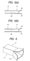
- Both the extension 211 and the stopper 212 of each of the connectors 2 may alternatively be, as shown in Fig. 5(a), expanded outward. This facilitates ease of insertion of the lead 16 into the connector 2.
- the extension 211 and the stopper 212 may also be, as shown in Fig. 5(b), chamfered or tapered. This provides for smooth insertion of the lead 16 into the connector 2.
- the head portion 21 may also, as shown in Fig. 6, have four extensions 213 expanding outward to work as stoppers. This absorbs shifts in location of the lead 16 from the end of the connector 2 in all directions and also facilitates ease of insertion of the lead 16 into the connector 2.
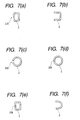
- the connectors 2 may be formed to various shapes in cross section, as shown in Figs. 7(a) to 7(f).
- the connector 2 of Fig. 7(a) has a longitudinally extending slit 209 formed in a side wall thereof.
- the connector of Fig. 7(b) is of C-shape in cross section defined by three side walls.
- the connector of Fig. 7(c) is of circular shape in cross section and has a longitudinally extending slit 209.
- the connector of Fig. 7(d) is, like Fig. 7(c), of circular shape in cross section, but has abutting ends 208 welded to each other.
- the connector of Fig. 7(e) is of rectangular shape in cross section and has abutting ends 208 welded to each other.
- the connector 2 of Fig. 7(f) is of U-shape in cross section.
- Fig. 8 shows a gas sensor 3 according to the second embodiment of the invention which is equipped with a cup-shaped sensing element 35.
- the sensing element 35 consists of a cup-shaped solid electrolyte body 358 and a bar-shaped heater 359.
- the solid electrolyte body 358 is retained in a hollow cylindrical housing 31.
- the heater 359 is disposed within the solid electrolyte body 358.
- the sensing element 35 and the housing 31 are hermetically sealed by a packing ring 311 placed on an annular shoulder formed on an inner wall of the housing 30, a sealing powder 312, and a ceramic cylinder 313.
- a metallic ring 314 is disposed on an end of the ceramic cylinder 313 and urged downward by a curved edge of the housing 31, as viewed in the drawing, to hold the sensing element 35 within the housing 31 firmly.
- a lead 361 is provided for electric connection between one of the connectors 2 and the sensing element 35.
- the lead 361 is made of a conductive strip which has formed at an end thereof a ring fitted on the base end of the sensing element 35 leading to a gas measuring electrode (not shown) formed on an outer wall of the solid electrolyte body 358.
- a lead 362 made of a conductive strip is provided for electric connection between the heater 359 and one of the connectors 2.
- the lead 362 has formed at an end thereof a cylindrical heater holder 365 which is fitted on the end of the heater 359 to hold it within the solid electrolyte body 358 and placed in electric contact with a reference gas electrode (not shown) formed on an inner wall of the solid electrolyte body 358.
- the gas measuring electrode and the reference gas electrode are known, for example, in European Patent Application EP 0918215 A2 assigned to the same assignee as that of this application, disclosure of which is incorporated herein by reference.
- the leads 361 and 362 extend through the holes 322 formed in an end surface of a hollow cylindrical insulation porcelain 32 and connect with the leads 17 through the connectors 2, respectively.
- the heater 359 is, like the solid electrolyte body 358, connected to the leads 17 through the connectors 2.
- Fig. 9 show a gas sensor according to the third embodiment of the invention which is different from the first embodiment only in that each of the connectors 2 has a stopper 41 formed on a side wall thereof.
- Other arrangements are identical, and explanation thereof in detail will be omitted here.
- Each of the connectors 2 is, as clearly shown in Fig. 10, made of a hollow rectangular conductive member which has a longitudinally extending slit 40 formed on one side wall thereof and a strip sheared out from an opposite side wall to define the stopper 41.
- Each of the connectors 2 is, as shown in Fig. 9, inserted partially into one of the holes 322 in contact of the stopper 41 with the end wall 323 of the second insulation porcelain 32, thereby avoiding an undesirable drop of the connector 2 into the hole 323.
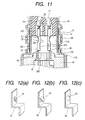
- Fig. 11 shows a gas sensor according to the fourth embodiment of the invention which is different from the first embodiment only in structure of the leads 16. Other arrangements are identical, and explanation thereof in detail will be omitted here.
- Each of the leads 16 is, as clearly shown in Fig. 12(a), made of a conductive plate which has a stopper 42 formed by shearing out a strip from a base portion of the conductive plate to be joined to the connector 2.
- the joining of the head 16 to the connector 2 is accomplished by inserting the base portion of the lead 16 into an end of the connector 2 as long as the stopper 42 advances and pressing the connector 2 in the same manner as described in the first embodiment.
- the stopper 42 extends out of the hole 322 of the second insulation porcelain 32, thereby avoiding an undesirable drop of the connector 2 into the hole 322.
- the stopper 42 may alternatively be, as shown in Fig. 12(b), made by shearing out half a width of the base portion of the lead 16 or pressing, as shown in Fig. 12(c), the base portion of the lead 16 to form a protrusion.
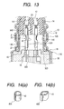
- Fig. 13 shows a gas sensor according to the fifth embodiment of the invention which is different from the first embodiment only in that a stopper 43 is provided independently from each of the connectors 2.
- Other arrangements are identical, and explanation thereof in detail will be omitted here.
- the stopper 43 is made of a material different from that of the lead 16 and formed by a hollow cylinder, as shown in Fig. 14(a), which has a slit 400 formed therein.
- the stopper 43 is disposed beneath each of the connectors 2 in partial contact with the end wall 323 of the second insulation porcelain 32, thereby avoiding an undesirable drop of the connector 2 into the hole 322 when the lead 16 is coupled to the connector 2.
- the stopper 43 may alternatively, as shown in Fig. 14(b), be made of a hollow member having a rectangular shape in cross section.
- Fig. 15 shows a gas sensor according to the sixth embodiment of the invention.
- Each of the connector 2 has a hollow cylindrical extension 219 which passes through the hole 322 and engages a shoulder 169 of the lead 16. Specifically, the extension 291 is placed in contact with the shoulder 169 of the lead 16, thereby keeping the press portion 201 at a constant level from the end wall 323 of the second insulation porcelain 32. This allows the connector 2 to be pressed and laser-welded to secure the lead 16 in a constant position.
Landscapes
- Chemical & Material Sciences (AREA)
- Life Sciences & Earth Sciences (AREA)
- Health & Medical Sciences (AREA)
- Physics & Mathematics (AREA)
- Chemical Kinetics & Catalysis (AREA)
- Electrochemistry (AREA)
- Molecular Biology (AREA)
- Analytical Chemistry (AREA)
- Biochemistry (AREA)
- General Health & Medical Sciences (AREA)
- General Physics & Mathematics (AREA)
- Immunology (AREA)
- Pathology (AREA)
- Measuring Oxygen Concentration In Cells (AREA)
Abstract
Description
Claims (16)
- A gas sensor comprising:a hollow cylindrical housing;a sensing element having a length which includes a sensing portion and a base portion, said sensing element being retained in said housing with the base portion projecting from said housing;a hollow insulating member provided so as to surround the base portion of said sensing element, said insulating member having a wall in which holes are formed;a cover covering said insulating member;first leads each having a first end portion and a second end portion, each of the first end portions being in electric contact with said sensing element within said insulating member, each of the second end portions passing through one of the through holes and projecting outside said insulating member;second leads each having a first end portion and a second end portion, the first end portion extending outside of the gas sensor for electric connection with an external device; andconnectors establishing electric connections between said first leads and said second leads, respectively, each of said connectors having a lead-joint portion and a stopper, each of the lead-joint portions electrically joining the second end portion of one of said first leads and the second end portion of a corresponding one of said second leads, each of the stoppers being placed in contact with the wall of said insulating member.
- A gas sensor as set forth in claim 1, wherein each of the stoppers is provided by an extension formed on an end of one of said connectors.
- A gas sensor as set forth in claim 1, wherein each of the stoppers is provided by a portion of one of the connectors which extends outward.
- A gas sensor as set forth in claim 1, wherein each of the stoppers has a tapered end wall for ease of insertion of the second end portion of one of said first leads.
- A gas sensor as set forth in claim 1, each of the stoppers has walls which define a rectangular shape in cross section and have ends expanding outward so that the ends are placed outside one of the holes of said insulating member in contact with the wall of said insulating member.
- A gas sensor as set forth in claim 1, wherein each of said connectors has a longitudinal slit formed therein.
- A gas sensor as set forth in claim 1, wherein said first leads and said second leads are joined to said connectors by pressing the lead-joint portions of said connector to plastically deform them or welding or soldering the lead-joint portions of said connectors and said first and second leads together.
- A gas sensor comprising:a hollow cylindrical housing;a sensing element having a length which includes a sensing portion and a base portion, said sensing element being retained in said housing with the base portion projecting from said housing;a hollow insulating member provided so as to surround the base portion of said sensing element, said insulating member having a wall in which holes are formed;a cover covering said insulating member;first leads each having a first end portion and a second end portion, each of the first end portions being in electric contact with said sensing element within said insulating member, each of the second end portions passing through one of the through holes and projecting outside said insulating member;second leads each having a first end portion and a second end portion, the first end portion extending outside of the gas sensor for electric connection with an external device;connectors establishing electric connections between the second end portions of said first leads and the second end portions of said second leads, respectively; andstoppers provided on one of the second end portions of said first leads in contact with the wall of said insulating member.
- A gas sensor as set forth in claim 8, wherein each of said connectors has a longitudinal slit formed therein.
- A gas sensor as set forth in claim 8, wherein said first leads and said second leads are joined to said connectors by pressing the lead-joint portions of said connector to plastically deform them or welding or soldering the lead-joint portions of said connectors and said first and second leads together.
- A gas sensor comprising:a hollow cylindrical housing;a sensing element having a length which includes a sensing portion and a base portion, said sensing element being retained in said housing with the base portion projecting from said housing;a hollow insulating member provided so as to surround the base portion of said sensing element, said insulating member having a wall in which holes are formed;a cover covering said insulating member;first leads each having a first end portion and a second end portion, each of the first end portions being in electric contact with said sensing element within said insulating member, each of the second end portions passing through one of the through holes and projecting outside said insulating member;second leads each having a first end portion and a second end portion, the first end portion extending outside of the gas sensor for electric connection with an external device;connectors establishing electric connections between the second end portions of said first leads and the second end portions of said second leads, respectively; andstoppers provided in contact with the wall of said insulating member to hold said connectors above the holes of said insulating member.
- A gas sensor as set forth in claim. 11, wherein each of said connectors has a longitudinal slit formed therein.
- A gas sensor as set forth in claim 11, wherein said first leads and said second leads are joined to said connectors by pressing the lead-joint portions of said connector to plastically deform them or welding or soldering the lead-joint portions of said connectors and said first and second leads together.
- A gas sensor comprising:a hollow cylindrical housing;a sensing element having a length which includes a sensing portion and a base portion, said sensing element being retained in said housing with the base portion projecting from said housing;a hollow insulating member provided so as to surround the base portion of said sensing element, said insulating member having a wall in which holes are formed;a cover covering said insulating member;first leads each having a first end portion and a second end portion, each of the first end portions having a shoulder and being in electric contact with said sensing element within said insulating member, each of the second end portions passing through one of the through holes and projecting outside said insulating member;second leads each having a first end portion and a second end portion, the first end portion extending outside of the gas sensor for electric connection with an external device;connectors establishing electric connections between the second end portions of said first leads and the second end portions of said second leads, respectively; andstoppers each provided by an extension formed on an end of one of said connectors, placed in contact with the shoulder of the first end portion of one of said first leads to hold the one of said connector.
- A gas sensor as set forth in claim 14, wherein each of said connectors has a longitudinal slit formed therein.
- A gas sensor as set forth in claim 14, wherein said first leads and said second leads are joined to said connectors by pressing the lead-joint portions of said connector to plastically deform them or welding or soldering the lead-joint portions of said connectors and said first and second leads together.
Applications Claiming Priority (4)
| Application Number | Priority Date | Filing Date | Title |
|---|---|---|---|
| JP2000150330 | 2000-05-22 | ||
| JP2000150330 | 2000-05-22 | ||
| JP2001051039A JP4479115B2 (en) | 2000-05-22 | 2001-02-26 | Gas sensor |
| JP2001051039 | 2001-02-26 |
Publications (3)
| Publication Number | Publication Date |
|---|---|
| EP1158295A2 true EP1158295A2 (en) | 2001-11-28 |
| EP1158295A3 EP1158295A3 (en) | 2005-03-16 |
| EP1158295B1 EP1158295B1 (en) | 2008-10-15 |
Family
ID=26592340
Family Applications (1)
| Application Number | Title | Priority Date | Filing Date |
|---|---|---|---|
| EP01112415A Expired - Lifetime EP1158295B1 (en) | 2000-05-22 | 2001-05-21 | Structure of electric connector of gas sensor |
Country Status (4)
| Country | Link |
|---|---|
| US (1) | US6463788B2 (en) |
| EP (1) | EP1158295B1 (en) |
| JP (1) | JP4479115B2 (en) |
| DE (1) | DE60136124D1 (en) |
Cited By (1)
| Publication number | Priority date | Publication date | Assignee | Title |
|---|---|---|---|---|
| CN103293206A (en) * | 2012-02-29 | 2013-09-11 | 日本特殊陶业株式会社 | Gas sensor |
Families Citing this family (30)
| Publication number | Priority date | Publication date | Assignee | Title |
|---|---|---|---|---|
| JP2002323475A (en) * | 2001-04-26 | 2002-11-08 | Ngk Spark Plug Co Ltd | Sensor |
| JP4578018B2 (en) * | 2001-04-26 | 2010-11-10 | 日本特殊陶業株式会社 | Sensor |
| JP2004093302A (en) * | 2002-08-30 | 2004-03-25 | Denso Corp | Gas sensor |
| US20040040370A1 (en) * | 2002-08-30 | 2004-03-04 | Takashi Kojima | Gas sensor having improved structure of electric connector |
| JP2004093303A (en) * | 2002-08-30 | 2004-03-25 | Denso Corp | Gas sensor |
| JP4172267B2 (en) * | 2002-12-20 | 2008-10-29 | 株式会社デンソー | Gas sensor |
| JP3894116B2 (en) * | 2002-12-20 | 2007-03-14 | 株式会社デンソー | Gas sensor |
| JP2004264262A (en) * | 2003-03-04 | 2004-09-24 | Denso Corp | Sliding contact structure between ceramic element and sliding terminal |
| JP2004296218A (en) * | 2003-03-26 | 2004-10-21 | Ngk Spark Plug Co Ltd | Sensor |
| DE10327186B4 (en) * | 2003-06-17 | 2006-11-30 | Robert Bosch Gmbh | probe |
| JP4728810B2 (en) * | 2003-11-04 | 2011-07-20 | テルモ株式会社 | Connector |
| AU2004285366B2 (en) * | 2003-11-04 | 2009-08-27 | Terumo Kabushiki Kaisha | Connector |
| US7178382B2 (en) * | 2003-12-24 | 2007-02-20 | Denso Corporation | Structure of gas sensor designed to reduce mechanical damage to sensor element |
| JP4631727B2 (en) * | 2006-01-30 | 2011-02-16 | 株式会社デンソー | Gas sensor |
| JP5099068B2 (en) * | 2009-04-23 | 2012-12-12 | 株式会社デンソー | Gas sensor and manufacturing method thereof |
| KR101281013B1 (en) * | 2010-07-27 | 2013-07-08 | 자동차부품연구원 | Gas sensor cap for vehicle |
| JP5529070B2 (en) * | 2011-05-02 | 2014-06-25 | 日本特殊陶業株式会社 | Gas sensor |
| JP5995765B2 (en) * | 2013-03-27 | 2016-09-21 | 日本特殊陶業株式会社 | Gas sensor |
| JP6331891B2 (en) * | 2014-08-29 | 2018-05-30 | 株式会社デンソー | Gas sensor |
| US10781062B2 (en) | 2015-11-24 | 2020-09-22 | Systems, LLC | Vehicle restraint system |
| JP6568009B2 (en) * | 2016-04-20 | 2019-08-28 | 日本特殊陶業株式会社 | Gas sensor |
| DE102017114083B4 (en) * | 2016-06-30 | 2026-02-05 | Niterra Co., Ltd. | Gas sensor and method for its manufacture |
| JP6875216B2 (en) * | 2016-07-07 | 2021-05-19 | 日本特殊陶業株式会社 | Gas sensor and manufacturing method of gas sensor |
| US10761048B2 (en) * | 2016-07-07 | 2020-09-01 | Ngk Spark Plug Co., Ltd. | Metal terminal for gas sensor, gas sensor and method for manufacturing gas sensor |
| US10745220B2 (en) | 2017-06-28 | 2020-08-18 | Systems, LLC | Vehicle Restraint System |
| US10906759B2 (en) | 2017-06-28 | 2021-02-02 | Systems, LLC | Loading dock vehicle restraint system |
| JP7265958B2 (en) * | 2019-08-07 | 2023-04-27 | 日本特殊陶業株式会社 | Sensor and its manufacturing method |
| JP7272923B2 (en) * | 2019-09-27 | 2023-05-12 | 日本碍子株式会社 | gas sensor |
| DE102020215863A1 (en) * | 2020-12-15 | 2022-06-15 | Robert Bosch Gesellschaft mit beschränkter Haftung | Device for connecting a sensor element of an exhaust gas sensor and exhaust gas sensor |
| JP7413989B2 (en) * | 2020-12-21 | 2024-01-16 | 株式会社デンソー | gas sensor |
Family Cites Families (25)
| Publication number | Priority date | Publication date | Assignee | Title |
|---|---|---|---|---|
| US4309897A (en) * | 1979-01-22 | 1982-01-12 | Ford Motor Company | Exhaust gas sensor seal and protection tube arrangement |
| US4214472A (en) * | 1979-01-22 | 1980-07-29 | Ford Motor Company | Exhaust gas oxygen sensor and electrical connector arrangement |
| JPS57178147A (en) * | 1981-04-27 | 1982-11-02 | Nippon Soken Inc | Detector for gaseous component |
| US4535316A (en) * | 1984-03-26 | 1985-08-13 | Allied Corporation | Heated titania oxygen sensor |
| JPH063429B2 (en) * | 1984-10-18 | 1994-01-12 | 日本碍子株式会社 | Oxygen sensor |
| JP2678084B2 (en) | 1990-08-31 | 1997-11-17 | シャープ株式会社 | Developing device and developer cartridge used therein |
| EP0506897B1 (en) | 1990-10-26 | 1995-12-06 | Robert Bosch Gmbh | Gas measurement probe, especially for determining the oxygen content in internal combustion engine exhaust gases |
| US5098548A (en) * | 1991-01-14 | 1992-03-24 | General Motors Corporation | Heated solid electrolyte oxygen sensor |
| DE4204850A1 (en) * | 1992-02-18 | 1993-08-19 | Roth Technik Gmbh | HOUSING FOR A GAS SENSOR |
| US5573650A (en) * | 1993-01-28 | 1996-11-12 | Nippondenso Co., Ltd. | Gas sensor |
| US5490412A (en) * | 1993-05-11 | 1996-02-13 | General Motors Corporation | Exhaust sensor with removable electrical connector |
| DE9401859U1 (en) * | 1994-02-04 | 1995-06-01 | Robert Bosch Gmbh, 70469 Stuttgart | Device for contacting a rod-shaped heating element of a sensor |
| US5593558A (en) * | 1994-06-09 | 1997-01-14 | Nippondenso Co., Ltd. | Oxygen concentration detector |
| EP0704697A1 (en) * | 1994-09-27 | 1996-04-03 | General Motors Corporation | Exhaust sensor including a ceramic tube in metal tube package |
| EP0704698A1 (en) * | 1994-09-27 | 1996-04-03 | General Motors Corporation | Exhaust sensor having flat plate ceramic sensing element and a sealing package |
| JP3539031B2 (en) * | 1996-01-18 | 2004-06-14 | 株式会社デンソー | Air-fuel ratio sensor |
| US5874664A (en) * | 1996-01-30 | 1999-02-23 | Denso Corporation | Air fuel ratio sensor and method for assembling the same |
| US5739414A (en) * | 1996-02-12 | 1998-04-14 | General Motors Corporation | Sensor with glass seal |
| DE19608543A1 (en) * | 1996-03-06 | 1997-09-11 | Bosch Gmbh Robert | Sensor |
| DE19638208C2 (en) * | 1996-09-19 | 2000-03-23 | Bosch Gmbh Robert | High temperature stable electrical contacting of a sensor element and method for their production |
| JP3322151B2 (en) * | 1997-02-19 | 2002-09-09 | トヨタ自動車株式会社 | Oxygen sensor |
| DE69822968T2 (en) * | 1997-11-21 | 2005-03-31 | Denso Corp., Kariya | gas sensor |
| DE29802115U1 (en) * | 1998-02-07 | 1999-06-02 | Robert Bosch Gmbh, 70469 Stuttgart | Connection plug for connecting the connections of a sensor |
| DE19850959A1 (en) * | 1998-11-05 | 2000-05-11 | Bosch Gmbh Robert | Sensor for determining the oxygen content in internal combustion engine exhaust gas has a one-part receiving molded part and an axial-symmetric cylindrical longitudinal bore and/or a gas-tight metal sleeve pressed around a sensor element |
| US6477887B1 (en) * | 1999-08-30 | 2002-11-12 | Masato Ozawa | Gas sensor having pre-stressed terminal for contact with inserted sensor element |
-
2001
- 2001-02-26 JP JP2001051039A patent/JP4479115B2/en not_active Expired - Fee Related
- 2001-05-21 DE DE60136124T patent/DE60136124D1/en not_active Expired - Lifetime
- 2001-05-21 US US09/860,781 patent/US6463788B2/en not_active Expired - Lifetime
- 2001-05-21 EP EP01112415A patent/EP1158295B1/en not_active Expired - Lifetime
Cited By (2)
| Publication number | Priority date | Publication date | Assignee | Title |
|---|---|---|---|---|
| CN103293206A (en) * | 2012-02-29 | 2013-09-11 | 日本特殊陶业株式会社 | Gas sensor |
| CN103293206B (en) * | 2012-02-29 | 2015-12-09 | 日本特殊陶业株式会社 | Gas sensor |
Also Published As
| Publication number | Publication date |
|---|---|
| JP2002048760A (en) | 2002-02-15 |
| JP4479115B2 (en) | 2010-06-09 |
| US6463788B2 (en) | 2002-10-15 |
| EP1158295B1 (en) | 2008-10-15 |
| DE60136124D1 (en) | 2008-11-27 |
| EP1158295A3 (en) | 2005-03-16 |
| US20020017127A1 (en) | 2002-02-14 |
Similar Documents
| Publication | Publication Date | Title |
|---|---|---|
| US6463788B2 (en) | Structure of electric connector of gas sensor | |
| US6898961B2 (en) | Compact structure of gas sensor and production method thereof | |
| EP1524518B1 (en) | Sensor, sensor producing method | |
| EP1081491B1 (en) | Gas sensor | |
| US6672136B2 (en) | Gas sensor having improved structure of electric connector | |
| EP0624790B1 (en) | Exhaust sensor with removable electrical connection | |
| US6708551B2 (en) | Insulator positioning structure of gas sensor | |
| US7424819B2 (en) | Gas sensor | |
| US7490404B2 (en) | Gas sensor manufacturing method | |
| EP0624791A1 (en) | Exhaust sensor with tubular shell | |
| US6222372B1 (en) | Structure of gas sensor | |
| EP0979996A2 (en) | Gas sensor | |
| US20060237315A1 (en) | Gas sensor | |
| US6817224B2 (en) | Structure of gas sensor | |
| US7138604B2 (en) | Ceramic device, sensor device, method of making the same, and method for sensing gas | |
| EP1394536A1 (en) | Gas sensor and structure of electric connector | |
| US4750256A (en) | Method of assembly of an O2 sensor | |
| KR100886333B1 (en) | Miniature coupler plug for flat broadband lambda probe | |
| JP3607817B2 (en) | Gas sensor | |
| JP2009210350A (en) | Gas sensor | |
| JP2004294220A (en) | Sensor terminal connection structure and sensor terminal connection method |
Legal Events
| Date | Code | Title | Description |
|---|---|---|---|
| PUAI | Public reference made under article 153(3) epc to a published international application that has entered the european phase |
Free format text: ORIGINAL CODE: 0009012 |
|
| AK | Designated contracting states |
Kind code of ref document: A2 Designated state(s): AT BE CH CY DE DK ES FI FR GB GR IE IT LI LU MC NL PT SE TR |
|
| AX | Request for extension of the european patent |
Free format text: AL;LT;LV;MK;RO;SI |
|
| PUAL | Search report despatched |
Free format text: ORIGINAL CODE: 0009013 |
|
| AK | Designated contracting states |
Kind code of ref document: A3 Designated state(s): AT BE CH CY DE DK ES FI FR GB GR IE IT LI LU MC NL PT SE TR |
|
| AX | Request for extension of the european patent |
Extension state: AL LT LV MK RO SI |
|
| 17P | Request for examination filed |
Effective date: 20050704 |
|
| AKX | Designation fees paid |
Designated state(s): DE FR GB |
|
| 17Q | First examination report despatched |
Effective date: 20051129 |
|
| GRAP | Despatch of communication of intention to grant a patent |
Free format text: ORIGINAL CODE: EPIDOSNIGR1 |
|
| GRAS | Grant fee paid |
Free format text: ORIGINAL CODE: EPIDOSNIGR3 |
|
| GRAA | (expected) grant |
Free format text: ORIGINAL CODE: 0009210 |
|
| AK | Designated contracting states |
Kind code of ref document: B1 Designated state(s): DE FR GB |
|
| REG | Reference to a national code |
Ref country code: GB Ref legal event code: FG4D |
|
| REF | Corresponds to: |
Ref document number: 60136124 Country of ref document: DE Date of ref document: 20081127 Kind code of ref document: P |
|
| REG | Reference to a national code |
Ref country code: GB Ref legal event code: 746 Effective date: 20090605 |
|
| PLBE | No opposition filed within time limit |
Free format text: ORIGINAL CODE: 0009261 |
|
| STAA | Information on the status of an ep patent application or granted ep patent |
Free format text: STATUS: NO OPPOSITION FILED WITHIN TIME LIMIT |
|
| 26N | No opposition filed |
Effective date: 20090716 |
|
| REG | Reference to a national code |
Ref country code: FR Ref legal event code: PLFP Year of fee payment: 15 |
|
| REG | Reference to a national code |
Ref country code: FR Ref legal event code: PLFP Year of fee payment: 16 |
|
| REG | Reference to a national code |
Ref country code: FR Ref legal event code: PLFP Year of fee payment: 17 |
|
| REG | Reference to a national code |
Ref country code: FR Ref legal event code: PLFP Year of fee payment: 18 |
|
| PGFP | Annual fee paid to national office [announced via postgrant information from national office to epo] |
Ref country code: DE Payment date: 20180522 Year of fee payment: 18 |
|
| PGFP | Annual fee paid to national office [announced via postgrant information from national office to epo] |
Ref country code: FR Payment date: 20180522 Year of fee payment: 18 |
|
| PGFP | Annual fee paid to national office [announced via postgrant information from national office to epo] |
Ref country code: GB Payment date: 20180518 Year of fee payment: 18 |
|
| REG | Reference to a national code |
Ref country code: DE Ref legal event code: R119 Ref document number: 60136124 Country of ref document: DE |
|
| GBPC | Gb: european patent ceased through non-payment of renewal fee |
Effective date: 20190521 |
|
| PG25 | Lapsed in a contracting state [announced via postgrant information from national office to epo] |
Ref country code: DE Free format text: LAPSE BECAUSE OF NON-PAYMENT OF DUE FEES Effective date: 20191203 Ref country code: GB Free format text: LAPSE BECAUSE OF NON-PAYMENT OF DUE FEES Effective date: 20190521 |
|
| PG25 | Lapsed in a contracting state [announced via postgrant information from national office to epo] |
Ref country code: FR Free format text: LAPSE BECAUSE OF NON-PAYMENT OF DUE FEES Effective date: 20190531 |