EP1158230A2 - Solenoid operated pressure control valve - Google Patents
Solenoid operated pressure control valve Download PDFInfo
- Publication number
- EP1158230A2 EP1158230A2 EP01111824A EP01111824A EP1158230A2 EP 1158230 A2 EP1158230 A2 EP 1158230A2 EP 01111824 A EP01111824 A EP 01111824A EP 01111824 A EP01111824 A EP 01111824A EP 1158230 A2 EP1158230 A2 EP 1158230A2
- Authority
- EP
- European Patent Office
- Prior art keywords
- armature
- flux
- air gap
- flux collector
- valve
- Prior art date
- Legal status (The legal status is an assumption and is not a legal conclusion. Google has not performed a legal analysis and makes no representation as to the accuracy of the status listed.)
- Granted
Links
- 230000004907 flux Effects 0.000 claims abstract description 58
- 239000012530 fluid Substances 0.000 claims description 7
- 230000000694 effects Effects 0.000 claims description 2
- 238000000034 method Methods 0.000 claims 4
- 238000004519 manufacturing process Methods 0.000 claims 1
- 230000000750 progressive effect Effects 0.000 claims 1
- 230000005540 biological transmission Effects 0.000 description 3
- 230000007423 decrease Effects 0.000 description 2
- 230000003247 decreasing effect Effects 0.000 description 2
- 230000000717 retained effect Effects 0.000 description 2
- 230000000740 bleeding effect Effects 0.000 description 1
- 230000005284 excitation Effects 0.000 description 1
- 230000004048 modification Effects 0.000 description 1
- 238000012986 modification Methods 0.000 description 1
- 125000006850 spacer group Chemical group 0.000 description 1
Images


Classifications
-
- F—MECHANICAL ENGINEERING; LIGHTING; HEATING; WEAPONS; BLASTING
- F16—ENGINEERING ELEMENTS AND UNITS; GENERAL MEASURES FOR PRODUCING AND MAINTAINING EFFECTIVE FUNCTIONING OF MACHINES OR INSTALLATIONS; THERMAL INSULATION IN GENERAL
- F16K—VALVES; TAPS; COCKS; ACTUATING-FLOATS; DEVICES FOR VENTING OR AERATING
- F16K31/00—Actuating devices; Operating means; Releasing devices
- F16K31/02—Actuating devices; Operating means; Releasing devices electric; magnetic
- F16K31/06—Actuating devices; Operating means; Releasing devices electric; magnetic using a magnet, e.g. diaphragm valves, cutting off by means of a liquid
- F16K31/0603—Multiple-way valves
- F16K31/061—Sliding valves
- F16K31/0613—Sliding valves with cylindrical slides
-
- G—PHYSICS
- G05—CONTROLLING; REGULATING
- G05D—SYSTEMS FOR CONTROLLING OR REGULATING NON-ELECTRIC VARIABLES
- G05D16/00—Control of fluid pressure
- G05D16/20—Control of fluid pressure characterised by the use of electric means
- G05D16/2006—Control of fluid pressure characterised by the use of electric means with direct action of electric energy on controlling means
- G05D16/2013—Control of fluid pressure characterised by the use of electric means with direct action of electric energy on controlling means using throttling means as controlling means
- G05D16/2024—Control of fluid pressure characterised by the use of electric means with direct action of electric energy on controlling means using throttling means as controlling means the throttling means being a multiple-way valve
-
- Y—GENERAL TAGGING OF NEW TECHNOLOGICAL DEVELOPMENTS; GENERAL TAGGING OF CROSS-SECTIONAL TECHNOLOGIES SPANNING OVER SEVERAL SECTIONS OF THE IPC; TECHNICAL SUBJECTS COVERED BY FORMER USPC CROSS-REFERENCE ART COLLECTIONS [XRACs] AND DIGESTS
- Y10—TECHNICAL SUBJECTS COVERED BY FORMER USPC
- Y10T—TECHNICAL SUBJECTS COVERED BY FORMER US CLASSIFICATION
- Y10T137/00—Fluid handling
- Y10T137/0318—Processes
- Y10T137/0402—Cleaning, repairing, or assembling
- Y10T137/0491—Valve or valve element assembling, disassembling, or replacing
- Y10T137/0502—Multi way valve
-
- Y—GENERAL TAGGING OF NEW TECHNOLOGICAL DEVELOPMENTS; GENERAL TAGGING OF CROSS-SECTIONAL TECHNOLOGIES SPANNING OVER SEVERAL SECTIONS OF THE IPC; TECHNICAL SUBJECTS COVERED BY FORMER USPC CROSS-REFERENCE ART COLLECTIONS [XRACs] AND DIGESTS
- Y10—TECHNICAL SUBJECTS COVERED BY FORMER USPC
- Y10T—TECHNICAL SUBJECTS COVERED BY FORMER US CLASSIFICATION
- Y10T137/00—Fluid handling
- Y10T137/8593—Systems
- Y10T137/86493—Multi-way valve unit
- Y10T137/86574—Supply and exhaust
- Y10T137/86622—Motor-operated
Definitions
- the present invention relates to solenoid operated valves employed for controlling flow of pressurized hydraulic fluid to actuators in an hydraulic system in response to an electrical control signal, such as provided by a microcomputer.
- Solenoid operated pressure control valves are employed in a variety of applications; one such application being for the control of shifting clutch actuators in an automatic transmissions for motor vehicles.
- electrically operated pressure control valves for controlling the shifting in an automatic transmission for a motor vehicle have employed a valving member configured as a spool with cylindrical valving lands provided thereon for controlling flow of hydraulic fluid between an inlet and a control or signal outlet port with pressure control provided by bleeding fluid through an exhaust outlet port which returns the flow to the source or sump.
- the magnetic force on a typical solenoid armature varies non-linearly with respect to armature movement.
- the magnetic force tends to increase exponentially thereby giving the resultant response of the valve spool connected to the armature undesirable valving characteristics.
- the exponential increase in the magnetic force causes prohibitively rapid opening and closing of the respective ports for given port and spool land configurations and thus renders proper control of the hydraulic pressure in the actuating circuit extremely difficult.
- the present invention addresses the above described problem and provides a solenoid operated pressure control valve of the type having a spool moveable in a valve body for controlling flow from an inlet to an control or signal outlet port and to a bleed port for maintaining pressure control.
- the spool of the valving member in the present invention has a pair of spaced lands for controlling flow respectively to the control and exhaust port in response to spool movement by the solenoid armature.
- the solenoid is constructed to provide reduced magnetic flux at one end of the armature as the working air gap on a remote end of the armature is closed by a given level at coil energization.
- the flux is decreased at the one end of the armature by a reduced area portion of the flux collector which surrounds the distal end of the armature forming an annular air gap therebetween.
- the decrease in flux at the remote end of the armature results in a substantially linear force versus stroke characteristics for the solenoid upon coil energization at a given level.
- the resultant pressure at the control pressure outlet is thus generally proportionally changed with respect to changing coil energization.
- valve assembly of the present invention is indicated generally at 10 and includes a valve body 12 attached to a base or mounting flux collector 14 which has received thereover and attached thereto one end of an outer flux member configured as cylindrical shell 16 and which is registered against shoulder 18 provided on the flux collector 14.
- Flux collector 14 has a reduced diameter annular portion 20 provided thereon and extending axially therefrom, the magnetic function of which will be hereinafter described.
- Valve body 12 has a valving bore 22 formed therein into which is slidably received in closely fitting arrangement a spool member 24 having a pair of spaced cylindrical valving lands 26, 28 formed thereon which may be lapped into bore 22, if desired to provide the desired close fit.
- Outer shell 16 has its opposite end connected to a second flux collector member 30 and registered against a shoulder 32 provided thereon.
- a coiled bobbin 34 is disposed within shell 16 and between the flux collectors 14, 30 and has an electrical coil 36 wound thereon as shown in FIG. 3.
- Each of the flux collectors 14, 30 has a bearing respectively 38, 40 disposed therein; and, an operating rod 42 is slidably disposed in the bearings 38, 40.
- Operating rod 42 has an armature 44 received thereover.
- Stop washer 46 acts as a magnetic spacer between armature 44 and pole piece 30.
- a spring retainer 48 is received over the end of rod 42 and a spring 50 has one end registered against the retainer 48 with the opposite end registered against the undersurface of an adjustment plug 52 which is threadedly engaged in the flux collector 30.
- Armature 44 has the end adjacent flux collector 30 tapered as indicated by reference numeral 54; and, flux collector 30 has a correspondingly configured tapered recess 56 formed therein which tapers 54, 56 define a working air gap between armature 44 and flux collector 30, a portion of which has an annular configuration.
- the inner periphery 54 of the reduced diameter portion 20 of flux collector 14 defines an annular air gap with the end of armature 44 distal the tapered end 54.
- the valve body 12 has an inlet port comprising apertures 60 formed adjacent the free end thereof in a collector ring 62; and, spaced along bore 22 is a control or signal pressure outlet comprising apertures 64 formed in a collector ring 66. Spaced further along bore 22 is an exhaust outlet comprising apertures 68.
- the inlet apertures 60 are located at a station along bore 22 such that valve land 28 is operable upon movement to control the flow through apertures 60 entering the valving bore 22 in the region intermediate lands 28, 26.
- Valving land 26 is operative to control the bleed flow through exhaust apertures 68 from bore 22.
- the exhaust port apertures 68 include a feathering notch denoted by reference numeral 72 to permit a small amount of hydraulic fluid to be exhausted upon initial opening of the exhaust port; and, conversely to prevent a sudden rapid close off of the exhaust port upon closing.
- valve spool 24 is retained in bore 22 by a spring 74 registering on one end thereof against a recess 76 formed in the end of land 28; and, at its opposite end the spring is retained by a cap 76 pressed in the end of valve body 12.
- a groove 78 is provided near the end of valve body 12 and has received therein a snap ring 80 which it will be understood is employed for retaining the valve body in a bore (not shown) in the hydraulic circuit of the device to be controlled.
- the spool 24 is shown in a low flow position where valving land 26 has only opened the feathering notch portion 72 of port 68; and, land 28 is positioned to permit only a small amount of flow through inlet port 60 to the bore 22; and, therefore the pressure in control port 64 is maintained at a low level.
- spool 24 is shown moved to a position where land 26 has closed the exhaust port 60; and, valving land 28 has substantially opened inlet port 60 allowing full flow to the control port 64.
- the pressure piece P c at the control outlet port 64 is plotted as a function of the coil excitation current I c ; and, it will be seen from FIG. 7 that the control pressure in port 64 increases generally proportional with respect to increasing coil current.
- the flux collector 30 has having a plurality of peripherally spaced cut-out formed therein which are disposed opposite corresponding cutouts 84 provided in cylindrical shell 16. Flux collector 30 is adjustably rotatable in shell 16 to vary the location of the slots 82, 84 with respect to each other for adjusting the flux nodes created thereby for calibrating armature movement with respect to a given level of coil energization.
- the tapered end of the armature may be alternatively reversed and attracted to the flux collector 14; and, if this alternate arrangement is employed, the tapered recess 56 will be provided in collector 14 if it is desired to reverse the movement of the armature with respect to coil energization for reverse valving movement of spool 24.
- portion 20 of flux collector 14 the effect of the decreased area of portion 20 of flux collector 14 is illustrated.
- the force characteristics of the solenoid as a function of armature stroke as shown in graphical representation; and, as illustrated are quite linear and have a sufficiently low slope as to be considered generally constant.
- the present invention thus permits a longer stroke of the armature for a given coil current and thereby provides for greater flexibility or higher resolution in controlling flow through the valve ports.
Landscapes
- Physics & Mathematics (AREA)
- Engineering & Computer Science (AREA)
- Fluid Mechanics (AREA)
- General Engineering & Computer Science (AREA)
- General Physics & Mathematics (AREA)
- Automation & Control Theory (AREA)
- Mechanical Engineering (AREA)
- Magnetically Actuated Valves (AREA)
- Control Of Fluid Pressure (AREA)
- Vehicle Body Suspensions (AREA)
- Fluid-Pressure Circuits (AREA)
- Valves And Accessory Devices For Braking Systems (AREA)
Abstract
The solenoid has a reduced area portion (20) of the flux collector (14) in magnetic loop forming an annular air gap remote from the working air gap. The reduced flux across the annular air gap compensates for the rapid flux increase as the working air gap closes.
Description
- Not Applicable
- Not Applicable
- Not Applicable
- The present invention relates to solenoid operated valves employed for controlling flow of pressurized hydraulic fluid to actuators in an hydraulic system in response to an electrical control signal, such as provided by a microcomputer. Solenoid operated pressure control valves are employed in a variety of applications; one such application being for the control of shifting clutch actuators in an automatic transmissions for motor vehicles.
- Heretofore, electrically operated pressure control valves for controlling the shifting in an automatic transmission for a motor vehicle have employed a valving member configured as a spool with cylindrical valving lands provided thereon for controlling flow of hydraulic fluid between an inlet and a control or signal outlet port with pressure control provided by bleeding fluid through an exhaust outlet port which returns the flow to the source or sump.
- In providing such an electrically operated pressure control valve for motor vehicle automatic transmission shift control, problems have been encountered in obtaining adequate pressure control over a wide range of flow required to provide the necessary shift actuator movement because of the magnetic characteristics of the actuating solenoid.
- For a given level of solenoid electrical energization, the magnetic force on a typical solenoid armature varies non-linearly with respect to armature movement. As the armature reduces the working air gap with the stationary pole piece or flux collector, the magnetic force tends to increase exponentially thereby giving the resultant response of the valve spool connected to the armature undesirable valving characteristics. The exponential increase in the magnetic force causes prohibitively rapid opening and closing of the respective ports for given port and spool land configurations and thus renders proper control of the hydraulic pressure in the actuating circuit extremely difficult.
- Accordingly, it has long been desired to provide a solenoid operated pressure control valve for controlling the flow of hydraulic fluid in an actuating circuit which provides a relatively long armature stroke with substantially linear response for a given level of solenoid energization and provides generally linear or proportional pressure control over the operating range of coil energization.
- The present invention addresses the above described problem and provides a solenoid operated pressure control valve of the type having a spool moveable in a valve body for controlling flow from an inlet to an control or signal outlet port and to a bleed port for maintaining pressure control. The spool of the valving member in the present invention has a pair of spaced lands for controlling flow respectively to the control and exhaust port in response to spool movement by the solenoid armature. The solenoid is constructed to provide reduced magnetic flux at one end of the armature as the working air gap on a remote end of the armature is closed by a given level at coil energization. The flux is decreased at the one end of the armature by a reduced area portion of the flux collector which surrounds the distal end of the armature forming an annular air gap therebetween. The decrease in flux at the remote end of the armature results in a substantially linear force versus stroke characteristics for the solenoid upon coil energization at a given level. The resultant pressure at the control pressure outlet is thus generally proportionally changed with respect to changing coil energization.
-
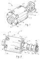
- FIG. 1 is a perspective view of the valve assembly of the present invention taken from the solenoid end;
- FIG. 2 is a view similar to FIG. 1 taken from the valve body end;
- FIG. 3 is a cross-section of the valve assembly of FIG. 1;
- FIG. 4 is an exploded view of valve assembly of FIG. 1;
- FIG. 5 is a portion of a cross-section similar to FIG. 3 showing the valve spool in a low flow position;
- FIG. 6 is a view similar to FIG. 5 showing the valve spoon in a high flow position;
- FIG. 7 is a graph of flow pressure at the control outlet plotted as a function of coil currents; and,
- FIG. 8 is a graph plotted of magnetic force on the armature as a function of armature stroke for a given level of coil current.
-
- Referring to FIGS. 1 through 4, the valve assembly of the present invention is indicated generally at 10 and includes a
valve body 12 attached to a base ormounting flux collector 14 which has received thereover and attached thereto one end of an outer flux member configured ascylindrical shell 16 and which is registered againstshoulder 18 provided on theflux collector 14.Flux collector 14 has a reduced diameterannular portion 20 provided thereon and extending axially therefrom, the magnetic function of which will be hereinafter described. -
Valve body 12 has avalving bore 22 formed therein into which is slidably received in closely fitting arrangement aspool member 24 having a pair of spacedcylindrical valving lands bore 22, if desired to provide the desired close fit. -
Outer shell 16 has its opposite end connected to a secondflux collector member 30 and registered against ashoulder 32 provided thereon. A coiledbobbin 34 is disposed withinshell 16 and between theflux collectors electrical coil 36 wound thereon as shown in FIG. 3. - Each of the
flux collectors operating rod 42 is slidably disposed in thebearings Operating rod 42 has anarmature 44 received thereover. Stopwasher 46 acts as a magnetic spacer betweenarmature 44 andpole piece 30. Aspring retainer 48 is received over the end ofrod 42 and aspring 50 has one end registered against theretainer 48 with the opposite end registered against the undersurface of anadjustment plug 52 which is threadedly engaged in theflux collector 30. -
Armature 44 has the endadjacent flux collector 30 tapered as indicated byreference numeral 54; and,flux collector 30 has a correspondingly configuredtapered recess 56 formed therein whichtapers armature 44 andflux collector 30, a portion of which has an annular configuration. - In the present practice of the invention, it has been found satisfactory to taper the
end 54 of the armature at an angle of twenty-two degrees (22°) to the coil axis. - Similarly, the
inner periphery 54 of the reduceddiameter portion 20 offlux collector 14 defines an annular air gap with the end ofarmature 44 distal thetapered end 54. - In the embodiment of FIGS. 1 through 4, the
valve body 12 has an inletport comprising apertures 60 formed adjacent the free end thereof in acollector ring 62; and, spaced alongbore 22 is a control or signal pressureoutlet comprising apertures 64 formed in a collector ring 66. Spaced further alongbore 22 is an exhaustoutlet comprising apertures 68. Theinlet apertures 60 are located at a station along bore 22 such thatvalve land 28 is operable upon movement to control the flow throughapertures 60 entering the valving bore 22 in the regionintermediate lands - Valving
land 26 is operative to control the bleed flow throughexhaust apertures 68 frombore 22. - As shown in dashed outline in FIG. 3, the
exhaust port apertures 68 include a feathering notch denoted byreference numeral 72 to permit a small amount of hydraulic fluid to be exhausted upon initial opening of the exhaust port; and, conversely to prevent a sudden rapid close off of the exhaust port upon closing. - The
valve spool 24 is retained inbore 22 by aspring 74 registering on one end thereof against arecess 76 formed in the end ofland 28; and, at its opposite end the spring is retained by acap 76 pressed in the end ofvalve body 12. - A
groove 78 is provided near the end ofvalve body 12 and has received therein asnap ring 80 which it will be understood is employed for retaining the valve body in a bore (not shown) in the hydraulic circuit of the device to be controlled. - Referring to FIG. 5, the
spool 24 is shown in a low flow position where valvingland 26 has only opened thefeathering notch portion 72 ofport 68; and,land 28 is positioned to permit only a small amount of flow throughinlet port 60 to thebore 22; and, therefore the pressure incontrol port 64 is maintained at a low level. - Referring to FIG. 6,
spool 24 is shown moved to a position whereland 26 has closed theexhaust port 60; and, valvingland 28 has substantially openedinlet port 60 allowing full flow to thecontrol port 64. - Referring to FIG. 7, the pressure piece Pc at the
control outlet port 64 is plotted as a function of the coil excitation current Ic; and, it will be seen from FIG. 7 that the control pressure inport 64 increases generally proportional with respect to increasing coil current. - Referring to FIGS. 1, 2 and 4, the
flux collector 30 is shown has having a plurality of peripherally spaced cut-out formed therein which are disposed oppositecorresponding cutouts 84 provided incylindrical shell 16.Flux collector 30 is adjustably rotatable inshell 16 to vary the location of theslots - It will be understood, that as the armature is attracted to
flux collector 30, and thetapered portion 54 ofarmature 44 closes against therecess 56, the magnetic flux across the tapered air gap increases generally exponentially. However, the reducedarea portion 20 offlux collector 14 decreases the flux across the annular air gap at the end ofarmature 44opposite taper 54 so as to compensate for the rapid increase in flux at the tapered end of the armature. - It will be understood that if so desired the tapered end of the armature may be alternatively reversed and attracted to the
flux collector 14; and, if this alternate arrangement is employed, thetapered recess 56 will be provided incollector 14 if it is desired to reverse the movement of the armature with respect to coil energization for reverse valving movement ofspool 24. - Referring to FIG. 8, the effect of the decreased area of
portion 20 offlux collector 14 is illustrated. The force characteristics of the solenoid as a function of armature stroke as shown in graphical representation; and, as illustrated are quite linear and have a sufficiently low slope as to be considered generally constant. The present invention thus permits a longer stroke of the armature for a given coil current and thereby provides for greater flexibility or higher resolution in controlling flow through the valve ports. - Although the invention has hereinabove been described with respect to the illustrated embodiments, it will be understood that the invention is capable of modification and variation and is limited only by the following claims.
Claims (15)
- A solenoid operated valve assembly comprising:(a) a valve body defining a valving chamber having an inlet port communicating with said chamber and at least one outlet port communicating with said chamber;(b) a valve member disposed in said chamber and moveable therein for, upon connection of a source of pressurized fluid to said inlet port, controlling fluid flow from said inlet port to said at least one outlet port;(c) a solenoid assembly including an armature guide attached to said valve body and an armature disposed for movement in said guide, wherein movement of said armature is operative for effecting said movement of said valve member;(d) a coil disposed about said armature guide and operative upon electrical energization to effect said movement of said armature; and,(e) a structure for completing a flux loop around said coil including an outer member and a first flux collector configured to form a working air gap with a first end portion of said armature, and a second flux collector forming an annular air gap with a second end portion of said armature distal said first end portion, said second flux collector having a reduced area portion such that, upon coil energization, and movement of said armature toward said first flux collector, the flux across said annular air gap is progressively reduced by said reduced area portion, thereby minimizing magnetic force increase caused by progressive reduction of said working air gap.
- The valve assembly defined in claim 1, wherein said reduced area portion of said second flux collector comprises an annular portion of reduced diameter.
- The valve assembly defined in claim 1, wherein said armature first end has a tapered configuration and said first flux collector includes a recess correspondingly tapered and said first air gap includes an annular tapered portion.
- The valve assembly defined in claim 1, wherein said outer member includes a plurality of surfaces defining a first set of flux nodes and said first flux collector includes a plurality of surfaces defining a second set of flux nodes, wherein said first flux collector is moveable for adjusting the flux between said first and second set of nodes.
- The valve assembly defined in claim 1, wherein said valve member comprises a spool and said at least one outlet port includes a first signal outlet port and a second bleed output port.
- The valve assembly defined in claim 1, wherein said at least one outlet port includes a pressure control outlet port and a bleed outlet port; and said valve member includes a spool having a first land controlling flow to said pressure control outlet and a second land controlling flow to said bleed outlet.
- The valve assembly defined in claim 1, wherein said outer member includes a generally cylindrical shell.
- The valve assembly defined in claim 1, wherein said outer member comprises a hollow cylindrical member having a set of flux nodes comprising a plurality of cut-outs on an end thereof.
- The valve assembly defined in claim 1, wherein said valve body is attached to said second flux collector.
- The valve assembly defined in claim 1, wherein upon coil energization the magnetic force on said armature varies as a function of armature movement substantially as shown in FIG. 8.
- A method of making a solenoid operated valve assembly comprising:(a) disposing a valve member in a valve body and moving said valve member and controlling flow from an inlet to at least one outlet;(b) disposing an armature in a valve guide and operatively connecting said armature for effecting said valve member moving;(c) disposing a coil over said armature and armature guide and completing a flux loop about said coil with an outer member and a first flux collector and forming a working air gap between said armature and the first flux collector and disposing a second flux collector spaced from said first flux collector and forming an annular air gap between said armature and said second flux collector;(d) forming a reduced area portion on said second flux collector and upon energization of said coil progressively reducing the flux across said second air gap and minimizing the increase in magnetic force as said working air gap is reduced.
- The method defined in claim 11, wherein said step of forming a reduced area portion includes forming a reduced diameter portion extending in a direction axially with respect to said coil.
- The method defined in claim 11, wherein said step of completing a flux loop includes forming a first set of flux nodes on said first flux collector and forming a second set of nodes on said outer member and rotating said first flux collector with respect to said outer member and calibrating movement of said armature.
- The method defined in claim 11, wherein said step of forming a working air gap includes tapering an end of said armature and forming a correspondingly tapered recess in said first flux collector.
- The method defined in claim 11, wherein said step of moving said valve member includes energizing said coil and applying a magnetic force to said armature which varies as a function of armature movement substantially as shown in FIG. 8.
Applications Claiming Priority (2)
| Application Number | Priority Date | Filing Date | Title |
|---|---|---|---|
| US575625 | 2000-05-22 | ||
| US09/575,625 US6386220B1 (en) | 2000-05-22 | 2000-05-22 | Solenoid operated pressure control valve |
Publications (3)
| Publication Number | Publication Date |
|---|---|
| EP1158230A2 true EP1158230A2 (en) | 2001-11-28 |
| EP1158230A3 EP1158230A3 (en) | 2003-01-22 |
| EP1158230B1 EP1158230B1 (en) | 2004-07-07 |
Family
ID=24301063
Family Applications (1)
| Application Number | Title | Priority Date | Filing Date |
|---|---|---|---|
| EP01111824A Expired - Lifetime EP1158230B1 (en) | 2000-05-22 | 2001-05-16 | Solenoid operated pressure control valve |
Country Status (10)
| Country | Link |
|---|---|
| US (1) | US6386220B1 (en) |
| EP (1) | EP1158230B1 (en) |
| JP (1) | JP2002013661A (en) |
| KR (1) | KR100828938B1 (en) |
| AT (1) | ATE270756T1 (en) |
| AU (1) | AU782844B2 (en) |
| BR (1) | BR0102818B1 (en) |
| CA (1) | CA2347610C (en) |
| DE (1) | DE60104168T2 (en) |
| ES (1) | ES2222290T3 (en) |
Cited By (6)
| Publication number | Priority date | Publication date | Assignee | Title |
|---|---|---|---|---|
| WO2004005678A1 (en) * | 2002-07-04 | 2004-01-15 | Ina-Schaeffler Kg | Electromagnetic hydraulic valve, in particular a proportional valve used for controlling an adjusting device for the angle of rotation of a camshaft with respect to the crankshaft of an internal combustion engine |
| WO2005124207A1 (en) * | 2004-06-21 | 2005-12-29 | Robertshaw Controls Company | Variable flow valve |
| EP1659321A1 (en) * | 2004-11-18 | 2006-05-24 | Eaton Corporation | Solenoid operated valve assembly and method of making the same |
| EP1752691A1 (en) * | 2005-08-09 | 2007-02-14 | Schaeffler KG | Control spool valve and its manufacturing process |
| US7806140B2 (en) | 2006-04-18 | 2010-10-05 | Robertshaw Controls Company | Power saving locking coil |
| ITMI20100350A1 (en) * | 2010-03-04 | 2011-09-05 | Bosch Gmbh Robert | SYSTEM FOR FUEL SUPPLY TO AN INTERNAL COMBUSTION ENGINE |
Families Citing this family (28)
| Publication number | Priority date | Publication date | Assignee | Title |
|---|---|---|---|---|
| US6435213B2 (en) * | 1999-04-23 | 2002-08-20 | Visteon Global Technologies, Inc. | Solenoid operated hydraulic control valve |
| US6959732B2 (en) * | 2003-02-21 | 2005-11-01 | Caterpillar Inc. | Hard coating on a stator for improving the durability of a solenoid actuator |
| DE10325178A1 (en) * | 2003-06-04 | 2005-01-05 | Hydac Fluidtechnik Gmbh | Proportional pressure control valve |
| JP4209281B2 (en) * | 2003-07-11 | 2009-01-14 | 日信工業株式会社 | Normally closed solenoid valve |
| US7051993B2 (en) * | 2004-03-10 | 2006-05-30 | Eaton Corporation | Solenoid operated valve and method of making same |
| US7325564B2 (en) * | 2004-03-24 | 2008-02-05 | Keihin Corporation | Linear solenoid valve |
| US7487798B2 (en) * | 2004-03-31 | 2009-02-10 | Keihin Corporation | Linear solenoid valve |
| US7458395B2 (en) * | 2004-06-07 | 2008-12-02 | Borgwarner Inc. | Low leak poppet solenoid |
| US20060197388A1 (en) * | 2005-03-02 | 2006-09-07 | Tae-Kyung Kim | Magnetic circuit apparatus and method |
| US20070056644A1 (en) * | 2005-09-13 | 2007-03-15 | Boddy Douglas E | Damper spool |
| US20070128756A1 (en) * | 2005-12-07 | 2007-06-07 | Bower Stephen P | Method and apparatus for determining density of metal-inclusive components |
| DE102006002638A1 (en) * | 2006-01-19 | 2007-07-26 | Robert Bosch Gmbh | magnetic valve |
| DE102007055054B4 (en) * | 2007-01-05 | 2014-03-20 | Hilite Germany Gmbh | Pressure valve with armature stroke limitation |
| DE102007009940B4 (en) * | 2007-03-01 | 2012-05-31 | Thomas Magnete Gmbh | Hydraulic way slide valve |
| US20080266038A1 (en) * | 2007-04-24 | 2008-10-30 | Eaton Corporation | Solenoid assembly |
| US8047503B2 (en) * | 2008-02-26 | 2011-11-01 | Eaton Corporation | Conical spring bushing |
| DE102009046186A1 (en) * | 2008-11-06 | 2010-05-20 | Kayaba Industry Co., Ltd. | Solenoid actuator |
| EP2536966A4 (en) * | 2010-02-18 | 2013-08-21 | Nt Consulting Int Pty Ltd | Solenoid spool valve |
| US8678033B2 (en) * | 2010-03-24 | 2014-03-25 | Eaton Corporation | Proportional valve employing simultaneous and hybrid actuation |
| JP5300822B2 (en) * | 2010-11-05 | 2013-09-25 | 日立オートモティブシステムズステアリング株式会社 | Pump device |
| JP2012151300A (en) * | 2011-01-19 | 2012-08-09 | Kawasaki Heavy Ind Ltd | Oil-immersed solenoid |
| JP5887170B2 (en) * | 2012-03-22 | 2016-03-16 | 日立オートモティブシステムズステアリング株式会社 | Solenoid valve and variable displacement pump |
| USD729346S1 (en) * | 2014-03-21 | 2015-05-12 | Fluid Automation Systems Sa | Valve |
| USD729347S1 (en) * | 2014-03-21 | 2015-05-12 | Fluid Automation Systems Sa | Valve |
| DE102015116464A1 (en) * | 2015-09-29 | 2017-03-30 | Voith Patent Gmbh | Electromagnetic actuator for performing a linear movement |
| KR101856967B1 (en) * | 2016-04-27 | 2018-06-28 | 주식회사 인팩 | Solenoid valve with spool |
| US10288190B2 (en) * | 2017-06-26 | 2019-05-14 | Schaeffler Technologies AG & Co. KG | Interlocking solenoid valve assembly and method |
| DE102019203028A1 (en) | 2019-03-06 | 2020-09-10 | Robert Bosch Gmbh | Electromagnetically operated actuator with progressive characteristic |
Family Cites Families (14)
| Publication number | Priority date | Publication date | Assignee | Title |
|---|---|---|---|---|
| JPS58156784A (en) * | 1982-03-12 | 1983-09-17 | Hitachi Ltd | Pulse-hydraulic converter |
| JPS60138080U (en) * | 1984-02-24 | 1985-09-12 | 三菱自動車工業株式会社 | Electromagnetic solenoid for hydraulic control |
| DE8626681U1 (en) * | 1986-10-08 | 1988-02-11 | Robert Bosch Gmbh, 70469 Stuttgart | Solenoid valve |
| JP2696235B2 (en) * | 1988-11-24 | 1998-01-14 | 株式会社不二越 | Hydraulic control valve |
| US5246033A (en) * | 1991-11-15 | 1993-09-21 | Robert Bosch Gmbh | Electromagnetically actuatable double seat valve |
| JPH0579154U (en) * | 1992-03-31 | 1993-10-26 | 豊田工機株式会社 | Solenoid spool valve |
| JP3155152B2 (en) * | 1994-05-24 | 2001-04-09 | 太平洋工業株式会社 | Proportional solenoid |
| US5607137A (en) | 1995-09-08 | 1997-03-04 | Eaton Corporation | Electrically operated flow control valve |
| JP3693080B2 (en) * | 1997-02-21 | 2005-09-07 | 株式会社デンソー | Linear solenoid |
| DE19716185A1 (en) * | 1997-04-18 | 1998-10-22 | Zahnradfabrik Friedrichshafen | Electromagnetic pressure control valve |
| US5853028A (en) | 1997-04-30 | 1998-12-29 | Eaton Corporation | Variable force solenoid operated valve assembly with dampener |
| JP3423581B2 (en) * | 1997-07-22 | 2003-07-07 | リンナイ株式会社 | Latch type solenoid valve |
| JP3577918B2 (en) * | 1997-10-27 | 2004-10-20 | 豊田工機株式会社 | solenoid valve |
| JPH11287348A (en) * | 1998-04-01 | 1999-10-19 | Tosok Corp | Proportional solenoid valve |
-
2000
- 2000-05-22 US US09/575,625 patent/US6386220B1/en not_active Expired - Lifetime
-
2001
- 2001-05-11 AU AU43840/01A patent/AU782844B2/en not_active Ceased
- 2001-05-16 AT AT01111824T patent/ATE270756T1/en not_active IP Right Cessation
- 2001-05-16 DE DE60104168T patent/DE60104168T2/en not_active Expired - Lifetime
- 2001-05-16 EP EP01111824A patent/EP1158230B1/en not_active Expired - Lifetime
- 2001-05-16 CA CA002347610A patent/CA2347610C/en not_active Expired - Fee Related
- 2001-05-16 ES ES01111824T patent/ES2222290T3/en not_active Expired - Lifetime
- 2001-05-18 KR KR1020010027232A patent/KR100828938B1/en not_active Expired - Fee Related
- 2001-05-22 BR BRPI0102818-9A patent/BR0102818B1/en not_active IP Right Cessation
- 2001-05-22 JP JP2001152557A patent/JP2002013661A/en active Pending
Non-Patent Citations (1)
| Title |
|---|
| None |
Cited By (7)
| Publication number | Priority date | Publication date | Assignee | Title |
|---|---|---|---|---|
| WO2004005678A1 (en) * | 2002-07-04 | 2004-01-15 | Ina-Schaeffler Kg | Electromagnetic hydraulic valve, in particular a proportional valve used for controlling an adjusting device for the angle of rotation of a camshaft with respect to the crankshaft of an internal combustion engine |
| WO2005124207A1 (en) * | 2004-06-21 | 2005-12-29 | Robertshaw Controls Company | Variable flow valve |
| US7455073B2 (en) | 2004-06-21 | 2008-11-25 | Robertshaw Controls Company | Variable flow valve |
| EP1659321A1 (en) * | 2004-11-18 | 2006-05-24 | Eaton Corporation | Solenoid operated valve assembly and method of making the same |
| EP1752691A1 (en) * | 2005-08-09 | 2007-02-14 | Schaeffler KG | Control spool valve and its manufacturing process |
| US7806140B2 (en) | 2006-04-18 | 2010-10-05 | Robertshaw Controls Company | Power saving locking coil |
| ITMI20100350A1 (en) * | 2010-03-04 | 2011-09-05 | Bosch Gmbh Robert | SYSTEM FOR FUEL SUPPLY TO AN INTERNAL COMBUSTION ENGINE |
Also Published As
| Publication number | Publication date |
|---|---|
| KR100828938B1 (en) | 2008-05-13 |
| JP2002013661A (en) | 2002-01-18 |
| DE60104168T2 (en) | 2005-08-04 |
| BR0102818B1 (en) | 2009-01-13 |
| US6386220B1 (en) | 2002-05-14 |
| CA2347610C (en) | 2006-07-18 |
| ATE270756T1 (en) | 2004-07-15 |
| DE60104168D1 (en) | 2004-08-12 |
| CA2347610A1 (en) | 2001-11-22 |
| ES2222290T3 (en) | 2005-02-01 |
| BR0102818A (en) | 2002-01-02 |
| KR20010107589A (en) | 2001-12-07 |
| AU782844B2 (en) | 2005-09-01 |
| EP1158230A3 (en) | 2003-01-22 |
| AU4384001A (en) | 2001-11-29 |
| EP1158230B1 (en) | 2004-07-07 |
Similar Documents
| Publication | Publication Date | Title |
|---|---|---|
| US6386220B1 (en) | Solenoid operated pressure control valve | |
| US5051631A (en) | Electromagnetic solenoid valve with variable force motor | |
| US6899313B2 (en) | Magnetic actuator and method | |
| US6918571B1 (en) | Solenoid operated valve assembly and method of making same | |
| US5607137A (en) | Electrically operated flow control valve | |
| US6343621B1 (en) | Variable force solenoid control valve | |
| JP3822667B2 (en) | Pressure switching valve | |
| US20060054852A1 (en) | Diaphragm and solenoid valve equipped with diaphragm | |
| JP4492649B2 (en) | Bleed valve device | |
| US5788213A (en) | Electrically operated pressure control valve | |
| EP1255067A1 (en) | Electrically operated pressure control valve | |
| US20090057594A1 (en) | Bleed valve apparatus | |
| EP1209327A2 (en) | Hydraulically damped low friction solenoid operated valve | |
| JPH10169822A (en) | solenoid valve | |
| JPH11280935A (en) | solenoid valve | |
| US20020117216A1 (en) | Solenoid operated valve with hydraulic dampening | |
| JPH0246384A (en) | Solenoid valve | |
| JP4129213B2 (en) | Electromagnetic actuator | |
| JP3767102B2 (en) | Solenoid valve | |
| JP4151335B2 (en) | solenoid valve | |
| EP0809057A1 (en) | Electromagnetically operated valve assembly | |
| JPH01316582A (en) | Electromagnetic working device | |
| JPH1038122A (en) | solenoid valve | |
| JPH0614649U (en) | Electromagnetic actuator | |
| JPH0557553U (en) | Electromagnetic actuator |
Legal Events
| Date | Code | Title | Description |
|---|---|---|---|
| PUAI | Public reference made under article 153(3) epc to a published international application that has entered the european phase |
Free format text: ORIGINAL CODE: 0009012 |
|
| AK | Designated contracting states |
Kind code of ref document: A2 Designated state(s): AT BE CH CY DE DK ES FI FR GB GR IE IT LI LU MC NL PT SE TR |
|
| AX | Request for extension of the european patent |
Free format text: AL;LT;LV;MK;RO;SI |
|
| PUAL | Search report despatched |
Free format text: ORIGINAL CODE: 0009013 |
|
| AK | Designated contracting states |
Kind code of ref document: A3 Designated state(s): AT BE CH CY DE DK ES FI FR GB GR IE IT LI LU MC NL PT SE TR |
|
| AX | Request for extension of the european patent |
Free format text: AL;LT;LV;MK;RO;SI |
|
| 17P | Request for examination filed |
Effective date: 20030408 |
|
| 17Q | First examination report despatched |
Effective date: 20030526 |
|
| AKX | Designation fees paid |
Designated state(s): AT BE CH CY DE DK ES FI FR GB GR IE IT LI LU MC NL PT SE TR |
|
| GRAP | Despatch of communication of intention to grant a patent |
Free format text: ORIGINAL CODE: EPIDOSNIGR1 |
|
| GRAS | Grant fee paid |
Free format text: ORIGINAL CODE: EPIDOSNIGR3 |
|
| GRAA | (expected) grant |
Free format text: ORIGINAL CODE: 0009210 |
|
| AK | Designated contracting states |
Kind code of ref document: B1 Designated state(s): AT BE CH CY DE DK ES FI FR GB GR IE IT LI LU MC NL PT SE TR |
|
| PG25 | Lapsed in a contracting state [announced via postgrant information from national office to epo] |
Ref country code: TR Free format text: LAPSE BECAUSE OF FAILURE TO SUBMIT A TRANSLATION OF THE DESCRIPTION OR TO PAY THE FEE WITHIN THE PRESCRIBED TIME-LIMIT Effective date: 20040707 Ref country code: FI Free format text: LAPSE BECAUSE OF FAILURE TO SUBMIT A TRANSLATION OF THE DESCRIPTION OR TO PAY THE FEE WITHIN THE PRESCRIBED TIME-LIMIT Effective date: 20040707 Ref country code: AT Free format text: LAPSE BECAUSE OF FAILURE TO SUBMIT A TRANSLATION OF THE DESCRIPTION OR TO PAY THE FEE WITHIN THE PRESCRIBED TIME-LIMIT Effective date: 20040707 Ref country code: LI Free format text: LAPSE BECAUSE OF FAILURE TO SUBMIT A TRANSLATION OF THE DESCRIPTION OR TO PAY THE FEE WITHIN THE PRESCRIBED TIME-LIMIT Effective date: 20040707 Ref country code: CH Free format text: LAPSE BECAUSE OF FAILURE TO SUBMIT A TRANSLATION OF THE DESCRIPTION OR TO PAY THE FEE WITHIN THE PRESCRIBED TIME-LIMIT Effective date: 20040707 Ref country code: BE Free format text: LAPSE BECAUSE OF FAILURE TO SUBMIT A TRANSLATION OF THE DESCRIPTION OR TO PAY THE FEE WITHIN THE PRESCRIBED TIME-LIMIT Effective date: 20040707 |
|
| REG | Reference to a national code |
Ref country code: GB Ref legal event code: FG4D |
|
| REG | Reference to a national code |
Ref country code: CH Ref legal event code: EP |
|
| REG | Reference to a national code |
Ref country code: IE Ref legal event code: FG4D |
|
| REF | Corresponds to: |
Ref document number: 60104168 Country of ref document: DE Date of ref document: 20040812 Kind code of ref document: P |
|
| REG | Reference to a national code |
Ref country code: SE Ref legal event code: TRGR |
|
| PG25 | Lapsed in a contracting state [announced via postgrant information from national office to epo] |
Ref country code: DK Free format text: LAPSE BECAUSE OF FAILURE TO SUBMIT A TRANSLATION OF THE DESCRIPTION OR TO PAY THE FEE WITHIN THE PRESCRIBED TIME-LIMIT Effective date: 20041007 Ref country code: GR Free format text: LAPSE BECAUSE OF FAILURE TO SUBMIT A TRANSLATION OF THE DESCRIPTION OR TO PAY THE FEE WITHIN THE PRESCRIBED TIME-LIMIT Effective date: 20041007 |
|
| REG | Reference to a national code |
Ref country code: CH Ref legal event code: PL |
|
| ET | Fr: translation filed | ||
| REG | Reference to a national code |
Ref country code: ES Ref legal event code: FG2A Ref document number: 2222290 Country of ref document: ES Kind code of ref document: T3 |
|
| PLBE | No opposition filed within time limit |
Free format text: ORIGINAL CODE: 0009261 |
|
| STAA | Information on the status of an ep patent application or granted ep patent |
Free format text: STATUS: NO OPPOSITION FILED WITHIN TIME LIMIT |
|
| PG25 | Lapsed in a contracting state [announced via postgrant information from national office to epo] |
Ref country code: CY Free format text: LAPSE BECAUSE OF FAILURE TO SUBMIT A TRANSLATION OF THE DESCRIPTION OR TO PAY THE FEE WITHIN THE PRESCRIBED TIME-LIMIT Effective date: 20050516 Ref country code: IE Free format text: LAPSE BECAUSE OF NON-PAYMENT OF DUE FEES Effective date: 20050516 Ref country code: LU Free format text: LAPSE BECAUSE OF NON-PAYMENT OF DUE FEES Effective date: 20050516 |
|
| PG25 | Lapsed in a contracting state [announced via postgrant information from national office to epo] |
Ref country code: MC Free format text: LAPSE BECAUSE OF NON-PAYMENT OF DUE FEES Effective date: 20050531 |
|
| 26N | No opposition filed |
Effective date: 20050408 |
|
| REG | Reference to a national code |
Ref country code: IE Ref legal event code: MM4A |
|
| PG25 | Lapsed in a contracting state [announced via postgrant information from national office to epo] |
Ref country code: PT Free format text: LAPSE BECAUSE OF NON-PAYMENT OF DUE FEES Effective date: 20041207 |
|
| PGFP | Annual fee paid to national office [announced via postgrant information from national office to epo] |
Ref country code: ES Payment date: 20080528 Year of fee payment: 8 |
|
| PGFP | Annual fee paid to national office [announced via postgrant information from national office to epo] |
Ref country code: IT Payment date: 20080521 Year of fee payment: 8 |
|
| PGFP | Annual fee paid to national office [announced via postgrant information from national office to epo] |
Ref country code: NL Payment date: 20080410 Year of fee payment: 8 |
|
| PGFP | Annual fee paid to national office [announced via postgrant information from national office to epo] |
Ref country code: GB Payment date: 20080407 Year of fee payment: 8 |
|
| GBPC | Gb: european patent ceased through non-payment of renewal fee |
Effective date: 20090516 |
|
| NLV4 | Nl: lapsed or anulled due to non-payment of the annual fee |
Effective date: 20091201 |
|
| PG25 | Lapsed in a contracting state [announced via postgrant information from national office to epo] |
Ref country code: NL Free format text: LAPSE BECAUSE OF NON-PAYMENT OF DUE FEES Effective date: 20091201 |
|
| REG | Reference to a national code |
Ref country code: FR Ref legal event code: ST Effective date: 20100129 |
|
| PG25 | Lapsed in a contracting state [announced via postgrant information from national office to epo] |
Ref country code: FR Free format text: LAPSE BECAUSE OF NON-PAYMENT OF DUE FEES Effective date: 20090602 |
|
| PGFP | Annual fee paid to national office [announced via postgrant information from national office to epo] |
Ref country code: FR Payment date: 20080424 Year of fee payment: 8 |
|
| PG25 | Lapsed in a contracting state [announced via postgrant information from national office to epo] |
Ref country code: GB Free format text: LAPSE BECAUSE OF NON-PAYMENT OF DUE FEES Effective date: 20090516 |
|
| REG | Reference to a national code |
Ref country code: ES Ref legal event code: FD2A Effective date: 20090518 |
|
| PG25 | Lapsed in a contracting state [announced via postgrant information from national office to epo] |
Ref country code: ES Free format text: LAPSE BECAUSE OF NON-PAYMENT OF DUE FEES Effective date: 20090518 |
|
| PG25 | Lapsed in a contracting state [announced via postgrant information from national office to epo] |
Ref country code: IT Free format text: LAPSE BECAUSE OF NON-PAYMENT OF DUE FEES Effective date: 20090516 |
|
| PGFP | Annual fee paid to national office [announced via postgrant information from national office to epo] |
Ref country code: SE Payment date: 20110506 Year of fee payment: 11 |
|
| REG | Reference to a national code |
Ref country code: SE Ref legal event code: EUG |
|
| PG25 | Lapsed in a contracting state [announced via postgrant information from national office to epo] |
Ref country code: SE Free format text: LAPSE BECAUSE OF NON-PAYMENT OF DUE FEES Effective date: 20120517 |
|
| REG | Reference to a national code |
Ref country code: DE Ref legal event code: R082 Ref document number: 60104168 Country of ref document: DE Ref country code: DE Ref legal event code: R081 Ref document number: 60104168 Country of ref document: DE Owner name: EATON INTELLIGENT POWER LIMITED, IE Free format text: FORMER OWNER: EATON CORP., CLEVELAND, OHIO, US |
|
| PGFP | Annual fee paid to national office [announced via postgrant information from national office to epo] |
Ref country code: DE Payment date: 20200421 Year of fee payment: 20 |
|
| REG | Reference to a national code |
Ref country code: DE Ref legal event code: R071 Ref document number: 60104168 Country of ref document: DE |