EP1158223A2 - Cylinder head gasket - Google Patents
Cylinder head gasket Download PDFInfo
- Publication number
- EP1158223A2 EP1158223A2 EP01110654A EP01110654A EP1158223A2 EP 1158223 A2 EP1158223 A2 EP 1158223A2 EP 01110654 A EP01110654 A EP 01110654A EP 01110654 A EP01110654 A EP 01110654A EP 1158223 A2 EP1158223 A2 EP 1158223A2
- Authority
- EP
- European Patent Office
- Prior art keywords
- cylinder head
- sealing plate
- chain case
- head gasket
- outer edge
- Prior art date
- Legal status (The legal status is an assumption and is not a legal conclusion. Google has not performed a legal analysis and makes no representation as to the accuracy of the status listed.)
- Granted
Links
Images


Classifications
-
- F—MECHANICAL ENGINEERING; LIGHTING; HEATING; WEAPONS; BLASTING
- F02—COMBUSTION ENGINES; HOT-GAS OR COMBUSTION-PRODUCT ENGINE PLANTS
- F02F—CYLINDERS, PISTONS OR CASINGS, FOR COMBUSTION ENGINES; ARRANGEMENTS OF SEALINGS IN COMBUSTION ENGINES
- F02F7/00—Casings, e.g. crankcases or frames
- F02F7/0065—Shape of casings for other machine parts and purposes, e.g. utilisation purposes, safety
- F02F7/0073—Adaptations for fitting the engine, e.g. front-plates or bell-housings
-
- F—MECHANICAL ENGINEERING; LIGHTING; HEATING; WEAPONS; BLASTING
- F16—ENGINEERING ELEMENTS AND UNITS; GENERAL MEASURES FOR PRODUCING AND MAINTAINING EFFECTIVE FUNCTIONING OF MACHINES OR INSTALLATIONS; THERMAL INSULATION IN GENERAL
- F16J—PISTONS; CYLINDERS; SEALINGS
- F16J15/00—Sealings
- F16J15/02—Sealings between relatively-stationary surfaces
- F16J15/06—Sealings between relatively-stationary surfaces with solid packing compressed between sealing surfaces
- F16J15/062—Sealings between relatively-stationary surfaces with solid packing compressed between sealing surfaces characterised by the geometry of the seat
-
- F—MECHANICAL ENGINEERING; LIGHTING; HEATING; WEAPONS; BLASTING
- F16—ENGINEERING ELEMENTS AND UNITS; GENERAL MEASURES FOR PRODUCING AND MAINTAINING EFFECTIVE FUNCTIONING OF MACHINES OR INSTALLATIONS; THERMAL INSULATION IN GENERAL
- F16J—PISTONS; CYLINDERS; SEALINGS
- F16J15/00—Sealings
- F16J15/02—Sealings between relatively-stationary surfaces
- F16J15/06—Sealings between relatively-stationary surfaces with solid packing compressed between sealing surfaces
- F16J15/08—Sealings between relatively-stationary surfaces with solid packing compressed between sealing surfaces with exclusively metal packing
- F16J15/0818—Flat gaskets
-
- F—MECHANICAL ENGINEERING; LIGHTING; HEATING; WEAPONS; BLASTING
- F16—ENGINEERING ELEMENTS AND UNITS; GENERAL MEASURES FOR PRODUCING AND MAINTAINING EFFECTIVE FUNCTIONING OF MACHINES OR INSTALLATIONS; THERMAL INSULATION IN GENERAL
- F16J—PISTONS; CYLINDERS; SEALINGS
- F16J15/00—Sealings
- F16J15/02—Sealings between relatively-stationary surfaces
- F16J15/14—Sealings between relatively-stationary surfaces by means of granular or plastic material, or fluid
-
- F—MECHANICAL ENGINEERING; LIGHTING; HEATING; WEAPONS; BLASTING
- F16—ENGINEERING ELEMENTS AND UNITS; GENERAL MEASURES FOR PRODUCING AND MAINTAINING EFFECTIVE FUNCTIONING OF MACHINES OR INSTALLATIONS; THERMAL INSULATION IN GENERAL
- F16J—PISTONS; CYLINDERS; SEALINGS
- F16J15/00—Sealings
- F16J15/02—Sealings between relatively-stationary surfaces
- F16J15/06—Sealings between relatively-stationary surfaces with solid packing compressed between sealing surfaces
- F16J15/08—Sealings between relatively-stationary surfaces with solid packing compressed between sealing surfaces with exclusively metal packing
- F16J15/0818—Flat gaskets
- F16J2015/0856—Flat gaskets with a non-metallic coating or strip
-
- F—MECHANICAL ENGINEERING; LIGHTING; HEATING; WEAPONS; BLASTING
- F16—ENGINEERING ELEMENTS AND UNITS; GENERAL MEASURES FOR PRODUCING AND MAINTAINING EFFECTIVE FUNCTIONING OF MACHINES OR INSTALLATIONS; THERMAL INSULATION IN GENERAL
- F16J—PISTONS; CYLINDERS; SEALINGS
- F16J15/00—Sealings
- F16J15/02—Sealings between relatively-stationary surfaces
- F16J15/06—Sealings between relatively-stationary surfaces with solid packing compressed between sealing surfaces
- F16J15/08—Sealings between relatively-stationary surfaces with solid packing compressed between sealing surfaces with exclusively metal packing
- F16J15/0818—Flat gaskets
- F16J2015/0862—Flat gaskets with a bore ring
-
- F—MECHANICAL ENGINEERING; LIGHTING; HEATING; WEAPONS; BLASTING
- F16—ENGINEERING ELEMENTS AND UNITS; GENERAL MEASURES FOR PRODUCING AND MAINTAINING EFFECTIVE FUNCTIONING OF MACHINES OR INSTALLATIONS; THERMAL INSULATION IN GENERAL
- F16J—PISTONS; CYLINDERS; SEALINGS
- F16J15/00—Sealings
- F16J15/02—Sealings between relatively-stationary surfaces
- F16J15/06—Sealings between relatively-stationary surfaces with solid packing compressed between sealing surfaces
- F16J15/08—Sealings between relatively-stationary surfaces with solid packing compressed between sealing surfaces with exclusively metal packing
- F16J15/0818—Flat gaskets
- F16J2015/0868—Aspects not related to the edges of the gasket
Definitions
- the invention relates to a cylinder head gasket for a a chain case multi-cylinder engine with a Engine block, a cylinder head and a chain case part, which occurs after that between the engine block and the cylinder head Clamping the sealing of the chain case serving cylinder head gasket is attached to the engine, the cylinder head gasket defining a plane has elongated sealing plate and the motor guide means through which the chain case part in the train its assembly in the longitudinal direction of the sealing plate parallel is guided to the sealing plate level; the Cylinder head gasket, with which the invention is concerned, has a group of combustion chamber openings, one between this group and a narrow side of the sealing plate Chain case opening, one between the latter and this narrow side of the sealing plate arranged sealing plate edge strips and the passage of cylinder head screws serving screw openings, and in particular the sealing plate is essentially of a or several sheet metal layers are formed.
- the chain case can be used for motors of the type defined above from a chain case upper part arranged next to the cylinder head and one next to the engine block or crankcase arranged chain box lower part are formed; but there are also constructions in which the upper part of the chain case is formed by the cylinder head, so that the latter overlaps the engine block and a chain case lower part, or where the lower part of the chain case from Engine block is formed over which the cylinder head and a Chain case upper part are arranged.
- Such an engine is used in the course of engine assembly usually first the chain box lower part with the Engine block screwed, which also the sealing of the Chain box-serving cylinder head gasket on engine block and the lower part of the chain case and then the cylinder head mounted with the cylinder head gasket between this and the engine block is clamped. Then will the chain case upper part from the side on the cylinder head Dowel pins provided and acting as guide means pushed on and through the cylinder head gasket with screwed to the lower part of the chain case and against the cylinder head gasket dressed.
- a cylinder head gasket whose sealing plate is only one Has sheet metal layer made of resilient material, can the bead is, for example, a cross-section act about U-shaped so-called full beads, whose Bead crest on one side of the cylinder head gasket forms the first such line and the two so-called Beading feet on the other side of the seal two such lines form; but there is also a so-called half bead Question, the cross section of an oblique step or a flat drawn Z corresponds and then on both sides of the Seal forms such a line.
- the beads are in those sheet metal layers formed which the two Form the main surfaces of the sealing plate.
- the chain case cavity has on average in the plane of the through the cylinder head gasket sealing gap to be sealed usually an approximate rectangular shape, the long sides of this rectangle approximately across the longitudinal direction of the elongate sealing plate the cylinder head gasket, and the Surrounding chain box cavity surrounds or beads or run between the chain case opening Cylinder head gasket and its screw openings for the Chain case cavity adjacent cylinder head bolts.
- the invention thus relates to a cylinder head gasket with the Features of the preamble of claim 1, and object of Invention was the such in such cylinder head gaskets Risk of damage from a side-to-side Eliminate chain box part or at least too minimize.
- the cylinder head gasket partially shown in Figure 1 has a sealing plate designated as a whole by 10, in of a plurality of through the sealing plate Openings are formed, for. B. combustion chamber openings 12, screw holes 14 for the passage of Cylinder head screws, and water or oil holes 16 or 18.
- the cylinder head gasket also includes a chain case opening 20, around the sealing surfaces of a chain case upper part and an adjacent cylinder head as well a chain case lower part and an adjacent engine block to seal against each other by the cylinder head gasket are.
- FIG. 2 shows, is the sealing plate 10 three-ply and includes two beaded outer or Cover layers 22 and 24 made of elastic properties Steel sheets and a metallic middle layer 26, which around the combustion chamber openings 12 folded back on themselves was and therefore usually as a flanged sheet layer referred to as.
- the edge of the sealing plate 10 adjacent locations are the three sheet metal layers 22, 24 and 26 connected by tubular rivets 28, such as this was shown in more detail in Figure 3.
- the height of the half bead 30 of the lower outer layer 24 formed "step” selects significantly larger (z. B. 0.45 mm) than the height of the half bead 30 of the upper outer layer 22 formed "step” (e.g. 0.25 mm).
- the sealing elements 50 are many times higher (according to FIG Figure 6 vertical dimension) as the outer layers 22 and 24 are thick - in a preferred embodiment it is Height of the sealing elements 50 0.7 to 0.9 mm, while the Sheet thickness of the outer layers 22 and 24 0.20 to 0.25 mm is.
- the sealing elements 50 that later form Sealing material on the middle layer 26 can be the sealing material enter the recess 56 of the middle layer, so as indicated in Figure 6.
- the sealing elements 50 can not yet in the unpressed seal Recesses 54 and 58 engage because at least the layers 24 and 26 of the sealing plate 10 are spaced apart can, as long as the seal is not clamped, d. H. is not yet pressed.
- the material of the sealing elements 50 occurs only when installing the seal and when clamping the Seal between the machine component sealing surfaces in the Recesses 54 and 58 in and through these recesses, so that it is over the two main surfaces of the sealing plate 10 protrudes and against the sealing surfaces 51 and 52 is pressed, especially in the area of the joints 42.
- the sealing material forms on the outside of the Sealing plate over the recess 54 an elongated, elastomeric rib, which is pressed against the sealing surface 52 will, thanks to the slight unevenness of the sealing surface 51 on the top (according to FIG. 6) of the seal a short, the elastomeric area of the Sealing elements 50 sufficient for reliable sealing is.
- sealing material beads for the production of the sealing elements to apply to the middle layer 26, with regard to the length, width and volume of these caterpillars controlled so that there are exactly the desired sealing elements 50 result.
- the sealing material beads applied to the sheet metal layer 26 before the layers 22, 24, 26 assembled to form the sealing plate 10 become.
- the chain case opening 20 extensive beads 30 in the immediate vicinity of screw holes 14 adjacent to the chain case opening; the same applies to beads 30 'which surround the group of combustion chamber openings 12 as well as the group of water and oil holes 16 or 18 run around.
- the beads 30 and / or the beads 30 ' now result in warpage of the sealing plate 10 if the cylinder head gasket when the upper part of the chain case is still missing 38 (by tightening cylinder head screws, not shown) between the engine block 36 and the cylinder head 34 is clamped; here tends due to the still missing Chain case upper part 38 an unsupported upward middle portion 100 of the gasket sheet edge strip shown in FIG. 1 102 to bulge up, d. H.
Abstract
Description
Die Erfindung betrifft eine Zylinderkopfdichtung für einen einen Kettenkasten aufweisenden Mehrzylindermotor mit einem Motorblock, einem Zylinderkopf sowie einem Kettenkastenteil, welches nach dem zwischen Motorblock und Zylinderkopf erfolgenden Einspannen der auch der Abdichtung des Kettenkastens dienenden Zylinderkopfdichtung am Motor angebracht wird, wobei die Zylinderkopfdichtung eine eine Ebene definierende längliche Dichtungsplatte aufweist und der Motor Führungsmittel besitzt, durch welche das Kettenkastenteil im Zuge seiner Montage in Längsrichtung der Dichtungsplatte parallel zur Dichtungsplattenebene verschiebbar geführt wird; die Zylinderkopfdichtung, mit welcher sich die Erfindung befaßt, weist eine Gruppe von Brennraumöffnungen, eine zwischen dieser Gruppe und einer Schmalseite der Dichtungsplatte angeordnete Kettenkastenöffnung, einen zwischen der letzteren und dieser Schmalseite der Dichtungsplatte angeordneten Dichtungsplatten-Randstreifen sowie dem Durchtritt von Zylinderkopfschrauben dienende Schraubenöffnungen auf, und insbesondere wird die Dichtungsplatte im wesentlichen von einer oder mehreren Metallblechlagen gebildet.The invention relates to a cylinder head gasket for a a chain case multi-cylinder engine with a Engine block, a cylinder head and a chain case part, which occurs after that between the engine block and the cylinder head Clamping the sealing of the chain case serving cylinder head gasket is attached to the engine, the cylinder head gasket defining a plane has elongated sealing plate and the motor guide means through which the chain case part in the train its assembly in the longitudinal direction of the sealing plate parallel is guided to the sealing plate level; the Cylinder head gasket, with which the invention is concerned, has a group of combustion chamber openings, one between this group and a narrow side of the sealing plate Chain case opening, one between the latter and this narrow side of the sealing plate arranged sealing plate edge strips and the passage of cylinder head screws serving screw openings, and in particular the sealing plate is essentially of a or several sheet metal layers are formed.
Bei Motoren der vorstehend definierten Art kann der Kettenkasten von einem neben dem Zylinderkopf angeordneten Kettenkasten-Oberteil und einem neben dem Motorblock bzw. Kurbelgehäuse angeordneten Kettenkasten-Unterteil gebildet werden; es gibt aber auch Konstruktionen, bei denen der obere Teil des Kettenkastens vom Zylinderkopf gebildet wird, so daß letzterer den Motorblock und ein Kettenkasten-Unterteil übergreift, oder bei denen der untere Teil des Kettenkastens vom Motorblock gebildet wird, über dem der Zylinderkopf und ein Kettenkasten-Oberteil angeordnet sind. In allen diesen Fällen ergibt sich in mindestens einer der Dichtflächen, zwischen denen die Zylinderkopfdichtung eingespannt wird und die vom Zylinderkopf sowie gegebenenfalls einem Kettenkasten-Oberteil bzw. vom Motorblock und gegebenenfalls einem Kettenkasten-Unterteil gebildet werden, eine Stoßstelle zwischen zwei gegeneinander anliegenden Motorbauteilen, welche aufgrund von Fertigungstoleranzen zu Abdichtproblemen führen kann, welche anhand einer Motorkonstruktion mit separatem Kettenkasten-Oberteil und separatem Kettenkasten-Unterteil erläutert werden sollen:The chain case can be used for motors of the type defined above from a chain case upper part arranged next to the cylinder head and one next to the engine block or crankcase arranged chain box lower part are formed; but there are also constructions in which the upper part of the chain case is formed by the cylinder head, so that the latter overlaps the engine block and a chain case lower part, or where the lower part of the chain case from Engine block is formed over which the cylinder head and a Chain case upper part are arranged. In all of these cases results in at least one of the sealing surfaces between which the cylinder head gasket is clamped and the Cylinder head and, if applicable, a chain case upper part or from the engine block and possibly a chain case lower part are formed, a joint between two mutually abutting engine components, which due to Manufacturing tolerances can lead to sealing problems, which based on a motor construction with a separate chain case upper part and separate chain case lower part explained should be:
Bei einem solchen Motor wird im Zuge der Motormontage üblicherweise zunächst das Kettenkasten-Unterteil mit dem Motorblock verschraubt, worauf die auch der Abdichtung des Kettenkastens dienende Zylinderkopfdichtung auf Motorblock und Kettenkasten-Unterteil aufgelegt und sodann der Zylinderkopf montiert und dabei die Zylinderkopfdichtung zwischen diesem und dem Motorblock eingespannt wird. Anschließend wird das Kettenkasten-Oberteil von der Seite her auf am Zylinderkopf vorgesehene und als Führungsmittel fungierende Paßstifte aufgeschoben und durch die Zylinderkopfdichtung hindurch mit dem Kettenkasten-Unterteil verschraubt sowie gegen die Zylinderkopfdichtung angezogen. Aufgrund von Fertigungs- und Montagetoleranzen kann sich in der gegen die eine Seite der Zylinderkopfdichtung anliegenden Dichtfläche im Bereich der Stoßstelle zwischen Motorblock und Kettenkasten-Unterteil eine Stufe ergeben, die dazu führt, daß der von der Oberseite des Kettenkasten-Unterteils gebildete Dichtflächenbereich um beispielsweise 0,2 ± 0,2 mm, d. h. bis zu 0,4 mm tiefer liegt als der von der Oberseite des Motorblocks gebildete Dichtflächenbereich; da die Montage des Kettenkasten-Oberteils auf Paßstiften und damit sehr genau erfolgt, ist das auf Fertigungstoleranzen zurückzuführende Risiko der Bildung einer nennenswerten Stufe in der anderen Dichtfläche sehr viel geringer, wenn auch nicht ausgeschlossen - auf jeden Fall ist jedoch die Höhe einer gegebenenfalls in der von Zylinderkopf und Kettenkasten-Oberteil gebildeten Dichtfläche vorhandenen Stufe deutlich geringer als die Höhe der in der anderen Dichtfläche gegebenenfalls vorhandenen Stufe.Such an engine is used in the course of engine assembly usually first the chain box lower part with the Engine block screwed, which also the sealing of the Chain box-serving cylinder head gasket on engine block and the lower part of the chain case and then the cylinder head mounted with the cylinder head gasket between this and the engine block is clamped. Then will the chain case upper part from the side on the cylinder head Dowel pins provided and acting as guide means pushed on and through the cylinder head gasket with screwed to the lower part of the chain case and against the cylinder head gasket dressed. Due to manufacturing and Assembly tolerances can differ in one side of the Cylinder head gasket in the area of the Joint between the engine block and the lower part of the chain case result in a level that leads to that of the top of the chain box lower part formed around the sealing surface for example 0.2 ± 0.2 mm, d. H. is up to 0.4 mm lower as the sealing surface area formed by the top of the engine block; because the assembly of the chain case upper part on Dowel pins and thus done very precisely, that is due to manufacturing tolerances risk due to the formation of a significant level in the other sealing surface very much lower, if not excluded - definitely however, the amount of one, if any, in that of cylinder head and chain case upper part formed sealing surface Level significantly lower than the level of the other Sealing surface of any existing step.
Um den Dichtspalt zwischen den beiden vorstehend erwähnten Dichtflächen auch im Falle des Vorhandenseins solcher Stufen zuverlässig abzudichten, und zwar auch um den Kettenkasten herum, dessen Hohlraum nicht ausschließlich im Kettenkasten-Oberteil und Kettenkasten-Unterteil ausgebildet ist, sondern teilweise auch von seitlichen Flächen des Motorblocks und des Zylinderkopfs begrenzt wird, so daß die von den beiden vorstehend beschriebenen Stoßstellen, welche in Richtung senkrecht zur Dichtspaltebene exakt übereinander liegen, definierte Teilungsebene den Kettenkasten-Hohlraum durchquert, ist es bei Zylinderkopfdichtungen, deren Dichtungsplatte von einer oder mehreren Metallblechlagen gebildet wird, üblich, um den Kettenkasten-Hohlraum herum mit mindestens einer federelastischen Sicke abzudichten, welche auf beiden Hauptoberflächen der Zylinderkopfdichtung um den Kettenkasten-Hohlraum herum mindestens eine in sich geschlossene Linie definiert, längs der sich eine erhöhte spezifische Flächenpressung zwischen der Zylinderkopfdichtung und den beiden den Dichtspalt begrenzenden Dichtflächen ergibt. Bei einer Zylinderkopfdichtung, deren Dichtungsplatte nur eine einzige Metallblechlage aus federelastischem Material aufweist, kann es sich bei der Sicke beispielsweise um eine im Querschnitt ungefähr U-förmige sogenannte Vollsicke handeln, deren Sickenkamm auf der einen Seite der Zylinderkopfdichtung eine erste derartige Linie bildet und deren beide sogenannten Sickenfüße auf der anderen Dichtungsseite zwei solche Linien bilden; es kommt aber auch eine sogenannte Halbsicke in Frage, deren Querschnitt einer schrägen Stufe oder einem flachgezogenen Z entspricht und die dann zu beiden Seiten der Dichtung eine solche Linie bildet. Bei Zylinderkopfdichtungen, deren Dichtungsplatte mehrere, aufeinandergeschichtete Metallblechlagen aufweist, sind die Sicken in denjenigen Metallblechlagen ausgebildet, welche die beiden Hauptoberflächen der Dichtungsplatte bilden.Around the sealing gap between the two mentioned above Sealing surfaces even in the presence of such steps seal reliably, even around the chain case around, whose cavity is not exclusively in the upper part of the chain case and chain case lower part is formed, but partly also from lateral surfaces of the engine block and the Cylinder head is limited so that of the two above described joints, which are perpendicular in the direction lie exactly one above the other to the sealing gap level Division level crosses the chain box cavity, it is with cylinder head gaskets, the gasket plate of one or more sheet metal layers is formed, usually around the chain case cavity with at least one to seal resilient beading, which on both main surfaces the cylinder head gasket around the chain case cavity around at least one self-contained line defined along which there is an increased specific surface pressure between the cylinder head gasket and the two the Sealing surfaces delimiting the sealing gap results. With a cylinder head gasket, whose sealing plate is only one Has sheet metal layer made of resilient material, can the bead is, for example, a cross-section act about U-shaped so-called full beads, whose Bead crest on one side of the cylinder head gasket forms the first such line and the two so-called Beading feet on the other side of the seal two such lines form; but there is also a so-called half bead Question, the cross section of an oblique step or a flat drawn Z corresponds and then on both sides of the Seal forms such a line. For cylinder head gaskets, whose sealing plate several, stacked Has sheet metal layers, the beads are in those sheet metal layers formed which the two Form the main surfaces of the sealing plate.
Zusätzlich zu solchen Sicken hat man Zylinderkopfdichtungen für derartige Motoren im Bereich der vorstehend beschriebenen Stufen bzw. Teilungsebene zu beiden Seiten des Kettenkasten-Hohlraums mit elastomeren Dichtelementen versehen, um die Stufen in den Dichtflächen zu überbrücken und im Bereich dieser Stufen zuverlässig abzudichten (siehe beispielsweise die DE-C-43 37 758 sowie die EP-B-0 701 051).In addition to such beads, you have cylinder head gaskets for such engines in the range described above Steps or division level on both sides of the chain box cavity provided with elastomeric sealing elements to the Bridging steps in the sealing surfaces and in the area seal these stages reliably (see for example DE-C-43 37 758 and EP-B-0 701 051).
Bei den in Rede stehenden, einen Kettenkasten aufweisenden Motoren wird die Zylinderkopfdichtung im Bereich von Motorblock und Zylinderkopf in der Nachbarschaft des Kettenkasten-Hohlraums von dem Einspannen der Zylinderkopfdichtung dienenden Zylinderkopfschrauben durchquert. Der Kettenkasten-Hohlraum hat im Schnitt in der Ebene des durch die Zylinderkopfdichtung abzudichtenden Dichtspalts üblicherweise eine ungefähr rechteckige Form, wobei die Längsseiten dieses Rechtecks ungefähr quer zur Längsrichtung der länglichen Dichtungsplatte der Zylinderkopfdichtung verlaufen, und die den Kettenkasten-Hohlraum umschließende Sicke bzw. Sicken verläuft bzw. verlaufen zwischen der Kettenkastenöffnung der Zylinderkopfdichtung und deren Schraubenöffnungen für die dem Kettenkasten-Hohlraum benachbarten Zylinderkopfschrauben. In the case of those in question that have a chain case Engines become the cylinder head gasket in the area of the engine block and cylinder head in the vicinity of the chain case cavity from clamping the cylinder head gasket Crossed cylinder head bolts. The chain case cavity has on average in the plane of the through the cylinder head gasket sealing gap to be sealed usually an approximate rectangular shape, the long sides of this rectangle approximately across the longitudinal direction of the elongate sealing plate the cylinder head gasket, and the Surrounding chain box cavity surrounds or beads or run between the chain case opening Cylinder head gasket and its screw openings for the Chain case cavity adjacent cylinder head bolts.
Wird nun nach der Montage des Kettenkasten-Unterteils (jedoch vor der Montage des Kettenkasten-Oberteils) die Zylinderkopfdichtung durch Anziehen der Zylinderkopfschrauben zwischen Motorblock und Zylinderkopf eingespannt, neigt infolge der elastischen Verformung der vorstehend beschriebenen Sicke bzw. Sicken die Dichtungsplatte der Zylinderkopfdichtung zu Verwerfungen mit der Folge, daß ein mittlerer Abschnitt eines zwischen der Kettenkastenöffnung und einem äußeren Schmalseitenrand der Dichtungsplatte liegenden Dichtungsplatten-Randstreifens zum Auswölben in Richtung auf den von dem noch zu montierenden Kettenkasten-Oberteil einzunehmenden Raum tendiert. Wird dann das Kettenkasten-Oberteil von der Seite her auf die am Zylinderkopf vorgesehenen Paßstifte aufgeschoben, besteht die Gefahr, daß der aufgewölbte Bereich des besagten Dichtungsplatten-Randstreifens beschädigt und dadurch das Abdichtvermögen der Zylinderkopfdichtung beeinträchtigt wird. Entsprechendes gilt für Zylinderkopfdichtungen für solche Motoren, welche nicht ein separates Kettenkasten-Oberteil und ein separates Kettenkasten-Unterteil, sondern nur ein separates Kettenkastenteil besitzen, welches dann nach dem Einspannen der Zylinderkopfdichtung von der Seite her auf Führungsmittel, wie auf Positionierstifte am Motorblock oder am Zylinderkopf, aufgeschoben wird.Is now after mounting the chain case lower part (however the cylinder head gasket before installing the upper part of the chain case) by tightening the cylinder head screws between Engine block and cylinder head clamped, tends as a result of elastic deformation of the bead described above or beads the sealing plate of the cylinder head gasket Faults with the result that a middle section of a between the chain case opening and an outer narrow side edge the sealing plate edge strip lying to bulge out towards the one from that space to be assembled in the upper part of the chain case tends. Then the chain case upper part from the side pushed onto the dowel pins provided on the cylinder head, there is a risk that the bulging area of the said sealing plate edge strip damaged and thereby the sealing ability of the cylinder head gasket is impaired becomes. The same applies to cylinder head gaskets for engines that do not have a separate chain case upper part and a separate chain case lower part, but only have a separate chain case part, which then after clamping the cylinder head gasket from the Side on guide means, as on positioning pins on Engine block or on the cylinder head.
Die Erfindung betrifft also eine Zylinderkopfdichtung mit den Merkmalen des Oberbegriffs des Anspruchs 1, und Aufgabe der Erfindung war es, bei solchen Zylinderkopfdichtungen die Gefahr einer Beschädigung durch ein von der Seite her einzuschiebendes Kettenkastenteil zu beseitigen oder mindestens zu minimieren.The invention thus relates to a cylinder head gasket with the Features of the preamble of claim 1, and object of Invention was the such in such cylinder head gaskets Risk of damage from a side-to-side Eliminate chain box part or at least too minimize.
Diese Aufgabe wird erfindungsgemäß dadurch gelöst, daß der äußere Randbereich des vorstehend beschriebenen mittleren Randstreifenabschnitts der Dichtungsplatte aus der Dichtungsplattenebene heraus in eine Richtung abgebogen wird, welche von dem nachträglich anzubringenden separaten Kettenkastenteil weg weist. Dadurch wird die Gefahr vermieden oder zumindest minimiert, daß es nach dem Einspannen der Zylinderkopfdichtung zwischen Motorblock und Zylinderkopf beim Einschieben des noch zu montierenden Kettenkastenteils zu einer eine Beschädigung der Zylinderkopfdichtung hervorrufenden Kollision zwischen dieser und diesem Kettenkastenteil kommt.This object is achieved in that the outer edge region of the middle described above Edge strip section of the sealing plate from the sealing plate plane is turned out in a direction which of the separate chain case part to be retrofitted points away. This avoids or at least avoids the danger minimized that after clamping the cylinder head gasket between engine block and cylinder head when inserting of the chain case part still to be assembled into one Damage to the cylinder head gasket causing collision comes between this and this chain case part.
Vorteilhafte Weiterbildungen der erfindungsgemäßen Zylinderkopfdichtung
ergeben sich aus den Ansprüchen 2 bis 4.Advantageous developments of the cylinder head gasket according to the invention
result from
Im folgenden wird die Erfindung anhand einer bevorzugten Ausführungsform einer erfindungsgemäßen Zylinderkopfdichtung noch näher erläutert, welche in den beigefügten Zeichnungen dargestellt ist; in diesen zeigen:
- Figur 1
- eine Draufsicht auf einen Teil der Zylinderkopfdichtung, welcher zwei Brennraum-Durchgangsöffnungen sowie eine Kettenkastenöffnung der Dichtung umfaßt;
- Figuren 2 - 4
- Schnitte nach den Linien 2-2, 3-3 und 4-4 in Figur 1;
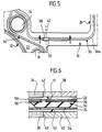
- Figur 5
- den in Figur 1 angedeuteten Ausschnitt "A" in größerem Maßstab, und
Figur 6- einen Schnitt nach der Linie 6-6 in Figur 5,
wobei in
Figur 6 auch Teile eines Motorblocks, eines Zylinderkopfs, eines Kettenkasten-Oberteils und eines Kettenkasten-Unterteils eines zu der Dichtung gehörenden Motors angedeutet wurden.
- Figure 1
- a plan view of a part of the cylinder head gasket, which comprises two combustion chamber through openings and a chain case opening of the gasket;
- Figures 2-4
- Cuts along lines 2-2, 3-3 and 4-4 in Figure 1;
- Figure 5
- the section "A" indicated in Figure 1 on a larger scale, and
- Figure 6
- a section along the line 6-6 in Figure 5, parts of an engine block, a cylinder head, a chain case upper part and a chain case lower part of an engine belonging to the seal were also indicated in Figure 6.
Die in Figur 1 teilweise dargestellte Zylinderkopfdichtung
hat eine als Ganzes mit 10 bezeichnete Dichtungsplatte, in
der eine Vielzahl von durch die Dichtungsplatte hindurchgehenden
Öffnungen ausgebildet sind, so z. B. Brennraumöffnungen
12, Schraubenlöcher 14 für den Durchtritt von
Zylinderkopfschrauben, und Wasser- bzw. Öllöcher 16 bzw. 18.
Außerdem beinhaltet die Zylinderkopfdichtung eine Kettenkastenöffnung
20, um die herum Dichtflächen eines Kettenkasten-Oberteils
und eines angrenzenden Zylinderkopfs sowie
eines Kettenkasten-Unterteils und eines angrenzenden Motorblocks
durch die Zylinderkopfdichtung gegeneinander abzudichten
sind.The cylinder head gasket partially shown in Figure 1
has a sealing plate designated as a whole by 10, in
of a plurality of through the sealing plate
Openings are formed, for. B.
Wie z. B. die Figur 2 erkennen läßt, ist die Dichtungsplatte
10 dreilagig und umfaßt zwei mit Sicken versehene Außen- oder
Decklagen 22 und 24 aus elastische Eigenschaften aufweisenden
Stahlblechen sowie eine metallische Mittellage 26, welche um
die Brennraumöffnungen 12 herum auf sich selbst zurückgefaltet
wurde und deshalb üblicherweise als Bördelblechlage
bezeichnet wird. An mehreren, dem Rand der Dichtungsplatte 10
benachbarten Stellen sind die drei Metallblechlagen 22, 24
und 26 durch Hohlniete 28 miteinander verbunden, so wie dies
in Figur 3 näher dargestellt wurde.Such as B. Figure 2 shows, is the
Um die Kettenkastenöffnung 20 herum verläuft sowohl in der
Außenlage 22, als auch in der Außenlage 24 jeweils eine Halbsicke
30 (siehe auch Figur 4), welche eine in sich geschlossene
Sickenlinie bildet und deren Kamm mit 30a bezeichnet
wurde. Around the chain case opening 20 runs both in the
In Figur 6 sind die für die vorliegende Erfindung relevanten
Motorbauteile angedeutet, wenn auch nur bereichsweise, nämlich
ein Zylinderkopf 34, ein Motorblock 36, ein Kettenkasten-Oberteil
38 und ein Kettenkasten-Unterteil 40; die
Stoßstellen, an denen der Zylinderkopf und das Kettenkasten-Oberteil
bzw. der Motorblock und das Kettenkasten-Unterteil
aneinandergrenzen (stumpf gegeneinander stoßen), wurden beide
mit 42 bezeichnet, da bei der dargestellten Ausführungsform
die beiden Stoß- oder Trennstellen exakt übereinanderliegen,
weshalb sie in Figur 5 auch nur durch eine einzige strichpunktierte
Linie angedeutet wurden.In Figure 6 are the relevant for the present invention
Engine components indicated, if only in certain areas, namely
a
Während im praktisch nur schwer realisierbaren Idealfall
Zylinderkopf und Kettenkasten-Oberteil bzw. Motorblock und
Kettenkasten-Unterteil durchgehende, ebene Dichtflächen
bilden, zwischen denen die Zylinderkopfdichtung eingespannt
wird, führen Fertigungs- und Montagetoleranzen oft dazu, daß
die in Figur 6 mit 51 bzw. 52 bezeichneten Dichtflächen an
den Stoßstellen 42 eine kleine Stufe bilden. Dabei ist die
Stufe in der Dichtfläche 52 in der Regel deutlich größer bzw.
höher als eine in der Dichtfläche 51 gegebenenfalls vorhandene
Stufe, da die Montage des Kettenkasten-Oberteils 38
oft auf Paßstiften und damit sehr genau erfolgt. So kann die
Dichtfläche 52 im Bereich des Kettenkasten-Unterteils 40 um
0,2 ± 0,2 mm, d. h. bis zu 0,4 mm, tiefer liegen als im Bereich
des Motorblocks 36, weshalb man erfindungsgemäß auch
die Höhe der von der Halbsicke 30 der unteren Außenlage 24
gebildeten "Stufe" deutlich größer wählt (z. B. 0,45 mm) als
die Höhe der von der Halbsicke 30 der oberen Außenlage 22
gebildete "Stufe" (z. B. 0,25 mm).While in the ideal case that is practically difficult to achieve
Cylinder head and chain case upper part or engine block and
Chain box lower part with continuous, flat sealing surfaces
form between which the cylinder head gasket is clamped
manufacturing and assembly tolerances often lead to the fact that
the sealing surfaces designated 51 and 52 in FIG. 6
the
Zu beiden Seiten der Kettenkastenöffnung 20 sind zwei im
wesentlichen strang- oder raupenförmige Dichtelemente 50
angeordnet, und zwar neben den Schmalseiten der Kettenkastenöffnung,
welche - in einer Draufsicht auf die Dichtung -
unterhalb und zwischen den Halbsicken 30 bzw. Sickenkämmen
30a liegen. Zur Erzeugung der Dichtelemente 50 werden auf die
Motorblock-seitige Oberfläche der Mittellage 26 zwei in ihrer
Länge der Länge der Dichtelemente 50 entsprechende Raupen aus
einem zunächst pastösen Dichtungsmaterial aufgetragen,
welches sich insbesondere durch Erwärmen so verfestigen läßt,
daß es zunächst außer elastischen auch noch plastische
Eigenschaften und sodann nur noch elastische Eigenschaften
aufweist. Wie sich der Figur 6 in Verbindung mit den Figuren
1 und 5 entnehmen läßt, weist die untere Außenlage 24 unter
jedem Dichtelement 50 eine fensterartige Aussparung 54 auf,
deren Gestalt einem Langloch bzw. einem langen, schmalen
Rechteck entspricht, welches sich in Längsrichtung des
benachbarten Dichtelements 50 erstreckt. Ferner haben die
Mittellage 26 und die obere Außenlage 22 über jedem
Dichtelement 50 jeweils eine weitere Aussparung 56 bzw. 58,
wobei diese beiden gleichfalls fensterartigen Aussparungen
vorzugsweise deckungsgleich übereinanderliegen und die Gestalt
eines deutlich kürzeren Langlochs (im Vergleich zur
Aussparung 54) besitzen. So haben bei einer bevorzugten Ausführungsform
die Aussparungen 54, 56 und 58 die folgenden
Abmessungen:
Die Dichtelemente 50 sind um ein Vielfaches höher (gemäß
Figur 6 vertikale Abmessung) als die Außenlagen 22 und 24
dick sind - bei einer bevorzugten Ausführungsform beträgt die
Höhe der Dichtelemente 50 0,7 bis 0,9 mm, während die
Blechstärke der Außenlagen 22 und 24 0,20 bis 0,25 mm
beträgt.The
Beim Auftragen des später die Dichtelemente 50 bildenden
Dichtungsmaterials auf die Mittellage 26 kann das Dichtungsmaterial
in die Aussparung 56 der Mittellage eintreten, so
wie dies in Figur 6 angedeutet wurde. Die Dichtelemente 50
können bei ungepreßter Dichtung jedoch auch noch nicht in die
Aussparungen 54 und 58 eingreifen, da zumindest die Lagen 24
und 26 der Dichtungsplatte 10 einen Abstand voneinander aufweisen
können, solange die Dichtung nicht eingespannt, d. h.
noch nicht gepreßt ist. Das Material der Dichtelemente 50
tritt erst beim Einbauen der Dichtung und beim Einspannen der
Dichtung zwischen den Maschinenbauteil-Dichtflächen in die
Aussparungen 54 und 58 ein und durch diese Aussparungen hindurch,
so daß es über die beiden Hauptoberflächen der Dichtungsplatte
10 übersteht und gegen die Dichtflächen 51 und 52
angepreßt wird, und zwar gerade im Bereich der Stoßstellen
42. Dabei bildet das Dichtungsmaterial auf der Außenseite der
Dichtungsplatte über der Aussparung 54 eine längliche,
elastomere Rippe, welche gegen die Dichtfläche 52 angepreßt
wird, während dank der geringen Unebenheiten der Dichtfläche
51 auf der Oberseite (gemäß Figur 6) der Dichtung ein kurzer,
aus der Aussparung 58 austretender elastomerer Bereich der
Dichtelemente 50 für eine zuverlässige Abdichtung ausreichend
ist.When applying the
Beim Herstellen der Flachdichtung ist es ohne weiteres möglich,
zur Herstellung der Dichtelemente 50 Dichtungsmaterial-Raupen
auf die Mittellage 26 aufzutragen, und zwar hinsichtlich
der Länge, der Breite und des Volumens dieser Raupen
derart gesteuert, daß sich exakt die gewünschten Dichtelemente
50 ergeben. Selbstverständlich werden die Dichtungsmaterial-Raupen
auf die Metallblechlage 26 aufgebracht, ehe
die Lagen 22, 24, 26 zu der Dichtungsplatte 10 zusammengesetzt
werden.When manufacturing the flat gasket, it is easily possible
50 sealing material beads for the production of the sealing elements
to apply to the
Wie die Fig. 1 zeigt, verlaufen die die Kettenkastenöffnung
20 umfassenden Sicken 30 in unmittelbarer Nachbarschaft von
der Kettenkastenöffnung benachbarten Schraubenlöchern 14;
gleiches gilt für Sicken 30', welche um die Gruppe von Brennraumöffnungen
12 sowie die Gruppe von Wasser- und Öllöchern
16 bzw. 18 herumlaufen. Die Sicken 30 und/oder die Sicken 30'
haben nun Verwerfungen der Dichtungsplatte 10 zur Folge, wenn
die Zylinderkopfdichtung bei noch fehlendem Kettenkasten-Oberteil
38 (durch Anziehen nicht gezeigter Zylinderkopfschrauben)
zwischen dem Motorblock 36 und dem Zylinderkopf 34
eingespannt wird; dabei neigt infolge des noch fehlenden
Kettenkasten-Oberteils 38 ein nach oben nicht abgestützter
mittlerer Abschnitt 100 des in Fig. 1 gezeigten Dichtungsplatten-Randstreifens
102 zum Aufwölben nach oben, d. h. in
Richtung auf den vom noch zu montierenden Kettenkasten-Oberteil
38 einzunehmenden Raum (siehe Fig. 6), was zur Folge
haben könnte, daß beim Aufschieben des Kettenkasten-Oberteils
38 gemäß den Figuren 1 und 6 von rechts die gemäß Fig. 1
rechte freie Kante des Randstreifenabschnitts 100 mit dem
Kettenkasten-Oberteil kollidiert und dabei die Zylinderkopfdichtung
beschädigt wird.As shown in Fig. 1, the chain case opening
20
Um dieses Risiko zu vermeiden, sind, wie in den Figuren 1 und
4 dargestellt, im Bereich des mittleren Randstreifenabschnitts
100 die äußeren Randbereiche der Außenlagen 22 und
24 längs einer Biegelinie 104 nach unten abgebogen - die
Mittellage 26 endet schon vor dieser Biegelinie, wie die Fig.
4 erkennen läßt. Um dieses Abbiegen zu erleichtern, bildet,
wie in Fig. 1 gezeigt, die Außenkante 106 der Dichtungsplatte
10 an beiden Enden des mittleren Randstreifenabschnitts 100
jeweils eine den äußeren Randbereich dieses Randstreifenabschnitts
freigebende Einbuchtung 108, welche bis über die
Biegelinie 104 hinaus in die Dichtungsplatte hineinragt.
Nachzutragen ist noch, daß bei der dargestellten bevorzugten
Ausführungsform die Biegelinie 104 ungefähr quer zur Längsrichtung
der Dichtungsplatte 10 verläuft (wie aus Fig. 1 geschlossen
werden kann, verläuft die Längsrichtung der Dichtungsplatte
10 gemäß Fig. 1 horizontal).To avoid this risk, as in FIGS
4, in the area of the central
Claims (4)
Applications Claiming Priority (4)
| Application Number | Priority Date | Filing Date | Title |
|---|---|---|---|
| DE10025400 | 2000-05-23 | ||
| DE10025400 | 2000-05-23 | ||
| DE10046502A DE10046502B4 (en) | 2000-05-23 | 2000-09-20 | Cylinder head gasket |
| DE10046502 | 2000-09-20 |
Publications (3)
| Publication Number | Publication Date |
|---|---|
| EP1158223A2 true EP1158223A2 (en) | 2001-11-28 |
| EP1158223A3 EP1158223A3 (en) | 2002-12-11 |
| EP1158223B1 EP1158223B1 (en) | 2004-03-24 |
Family
ID=26005788
Family Applications (1)
| Application Number | Title | Priority Date | Filing Date |
|---|---|---|---|
| EP01110654A Expired - Lifetime EP1158223B1 (en) | 2000-05-23 | 2001-05-02 | Cylinder head gasket |
Country Status (3)
| Country | Link |
|---|---|
| US (1) | US6641142B2 (en) |
| EP (1) | EP1158223B1 (en) |
| ES (1) | ES2215810T3 (en) |
Cited By (1)
| Publication number | Priority date | Publication date | Assignee | Title |
|---|---|---|---|---|
| EP1538326A1 (en) * | 2003-12-02 | 2005-06-08 | GE Jenbacher GmbH & Co. OHG | Arrangement for sealably and removably connecting two workpieces |
Families Citing this family (13)
| Publication number | Priority date | Publication date | Assignee | Title |
|---|---|---|---|---|
| JP2004308761A (en) * | 2003-04-07 | 2004-11-04 | Uchiyama Mfg Corp | Multifunction gasket |
| DE10328158B4 (en) * | 2003-06-24 | 2006-06-01 | Federal-Mogul Sealing Systems Gmbh | Cylinder head gasket |
| DE102006014386A1 (en) * | 2006-03-29 | 2007-10-11 | Elringklinger Ag | Flat gasket, in particular cylinder head gasket |
| ATE546674T1 (en) * | 2008-06-21 | 2012-03-15 | Federal Mogul Sealing Sys Spa | FLAT SEAL |
| GB0922625D0 (en) * | 2009-12-24 | 2010-02-10 | Flexitallic Ltd | A gasket |
| JP5061204B2 (en) * | 2010-01-07 | 2012-10-31 | 株式会社豊田自動織機 | Cylinder head gasket |
| US8500131B2 (en) * | 2010-12-02 | 2013-08-06 | Dana Automotive Systems Group, Llc | Exhaust manifold gasket |
| US20130106063A1 (en) * | 2011-11-02 | 2013-05-02 | Dana Automotive Systems Group, Llc | Multi-Layer Inserts for Gaskets |
| US20130106065A1 (en) * | 2011-11-02 | 2013-05-02 | Dana Automotive Systems Group, Llc | Multi-Layer Inserts for Gaskets |
| DE102012109646A1 (en) * | 2012-10-10 | 2014-04-10 | Elringklinger Ag | Cylinder head gasket |
| US9970548B2 (en) | 2013-03-14 | 2018-05-15 | Federal-Mogul Llc | Multi-layer gasket |
| AT515952B1 (en) | 2014-06-20 | 2016-08-15 | Engel Austria Gmbh | Melting and injection device for plastics |
| EP4091889A1 (en) * | 2021-05-19 | 2022-11-23 | ZF CV Systems Europe BV | Gasket device for a pneumatic valve system in particular of a commercial vehicle |
Citations (2)
| Publication number | Priority date | Publication date | Assignee | Title |
|---|---|---|---|---|
| DE4337758C1 (en) | 1993-11-05 | 1995-01-26 | Goetze Ag | Cylinder head gasket |
| EP0701051B1 (en) | 1994-09-06 | 1999-03-24 | Nippon Gasket Co., Ltd. | Metal gasket for chain casing engines |
Family Cites Families (10)
| Publication number | Priority date | Publication date | Assignee | Title |
|---|---|---|---|---|
| ATE19427T1 (en) | 1981-03-06 | 1986-05-15 | Lechler Elring Dichtungswerke | FLAT GASKET. |
| JPS58106264A (en) * | 1981-12-16 | 1983-06-24 | Nichias Corp | Heat-resisting sheet gasket |
| JPH0645095Y2 (en) * | 1988-05-28 | 1994-11-16 | 石川ガスケット株式会社 | Metal laminated gasket |
| JPH09177605A (en) * | 1995-12-22 | 1997-07-11 | Nippon Gasket Co Ltd | Sealing structure for gasket connection part |
| US5895056A (en) * | 1996-04-09 | 1999-04-20 | Nippon Gasket Co., Ltd. | Metal gasket with seal members at an area between a main seal portion and a sub-seal portion |
| JPH09280110A (en) * | 1996-04-09 | 1997-10-28 | Nippon Gasket Co Ltd | Gasket made of metal |
| JPH10292865A (en) * | 1997-04-18 | 1998-11-04 | Nippon Gasket Co Ltd | Metal gasket having three-face uniting seal structure |
| DE19809755B4 (en) * | 1998-03-06 | 2008-01-03 | Reinz-Dichtungs-Gmbh | Cylinder head gasket |
| JP2000240798A (en) * | 1999-02-22 | 2000-09-05 | Honda Motor Co Ltd | Seal structure |
| JP2002081543A (en) * | 2000-09-04 | 2002-03-22 | Nippon Gasket Co Ltd | Metal gasket |
-
2001
- 2001-05-02 ES ES01110654T patent/ES2215810T3/en not_active Expired - Lifetime
- 2001-05-02 EP EP01110654A patent/EP1158223B1/en not_active Expired - Lifetime
- 2001-05-07 US US09/850,215 patent/US6641142B2/en not_active Expired - Fee Related
Patent Citations (2)
| Publication number | Priority date | Publication date | Assignee | Title |
|---|---|---|---|---|
| DE4337758C1 (en) | 1993-11-05 | 1995-01-26 | Goetze Ag | Cylinder head gasket |
| EP0701051B1 (en) | 1994-09-06 | 1999-03-24 | Nippon Gasket Co., Ltd. | Metal gasket for chain casing engines |
Cited By (1)
| Publication number | Priority date | Publication date | Assignee | Title |
|---|---|---|---|---|
| EP1538326A1 (en) * | 2003-12-02 | 2005-06-08 | GE Jenbacher GmbH & Co. OHG | Arrangement for sealably and removably connecting two workpieces |
Also Published As
| Publication number | Publication date |
|---|---|
| ES2215810T3 (en) | 2004-10-16 |
| EP1158223A3 (en) | 2002-12-11 |
| EP1158223B1 (en) | 2004-03-24 |
| US20010048200A1 (en) | 2001-12-06 |
| US6641142B2 (en) | 2003-11-04 |
Similar Documents
| Publication | Publication Date | Title |
|---|---|---|
| EP1158223B1 (en) | Cylinder head gasket | |
| DE4309088A1 (en) | Window which can be installed such that it is fixed in place, for motor vehicles | |
| DE3943177C2 (en) | Cylinder head gasket | |
| EP1482218B1 (en) | Cylinder head gasket | |
| EP1389701B1 (en) | Multi-layered gasket and method for joining the layers of a multi-layered gasket | |
| DE19751293A1 (en) | Single-layer or multi-layer metal cylinder head gasket and process for its manufacture | |
| EP1158224B1 (en) | Flat gasket | |
| EP1158225B1 (en) | Flat gasket | |
| EP1628050B1 (en) | Metallic gasket with reduced sealing layer | |
| DE19630152C1 (en) | Positive connection for long seal in internal combustion engines | |
| EP1869278B1 (en) | Composite profile and method for making a composite profile for frames of wall elements, doors and windows | |
| DE10046502A1 (en) | Cylinder head gasket | |
| DE102006007270B4 (en) | gasket | |
| EP0926407B1 (en) | Cylinder head gasket | |
| EP0695867B1 (en) | Frame-shaped gasket especially for cover of an internal combustion engine | |
| DE102013227113A1 (en) | Heat exchanger with circumferential seal | |
| WO2004081424A1 (en) | Flat gasket, in particular cylinder-head gasket | |
| EP0950842B1 (en) | Metallic cylinder head gasket | |
| DE19844217C1 (en) | Cylinder head gasket for internal combustion engine has sealing layers with offset sealing planes defining recesses filled with adhesive | |
| DD296866A5 (en) | METHOD FOR PRODUCING A CONTACT ELEMENT FOR A FILM CONNECTOR AND A CONTACT ELEMENT FOR SUCH A FILM CONNECTOR | |
| DE10152797A1 (en) | Multi-layer seal | |
| DE10152796B4 (en) | Multi-layer seal | |
| EP0525661A1 (en) | Shuttering for concrete construction and method for the manufacturing of the shuttering | |
| CH675614A5 (en) | ||
| EP0616124A1 (en) | Multi-layered cylinderhead gasket for an internal combustion engine |
Legal Events
| Date | Code | Title | Description |
|---|---|---|---|
| PUAI | Public reference made under article 153(3) epc to a published international application that has entered the european phase |
Free format text: ORIGINAL CODE: 0009012 |
|
| AK | Designated contracting states |
Kind code of ref document: A2 Designated state(s): AT BE CH CY DE DK ES FI FR GB GR IE IT LI LU MC NL PT SE TR |
|
| AX | Request for extension of the european patent |
Free format text: AL;LT;LV;MK;RO;SI |
|
| PUAL | Search report despatched |
Free format text: ORIGINAL CODE: 0009013 |
|
| AK | Designated contracting states |
Kind code of ref document: A3 Designated state(s): AT BE CH CY DE DK ES FI FR GB GR IE IT LI LU MC NL PT SE TR |
|
| AX | Request for extension of the european patent |
Free format text: AL;LT;LV;MK;RO;SI |
|
| 17P | Request for examination filed |
Effective date: 20030114 |
|
| GRAP | Despatch of communication of intention to grant a patent |
Free format text: ORIGINAL CODE: EPIDOSNIGR1 |
|
| AKX | Designation fees paid |
Designated state(s): DE ES FR GB IT |
|
| GRAS | Grant fee paid |
Free format text: ORIGINAL CODE: EPIDOSNIGR3 |
|
| GRAA | (expected) grant |
Free format text: ORIGINAL CODE: 0009210 |
|
| AK | Designated contracting states |
Kind code of ref document: B1 Designated state(s): DE ES FR GB IT |
|
| REG | Reference to a national code |
Ref country code: GB Ref legal event code: FG4D Free format text: NOT ENGLISH |
|
| REG | Reference to a national code |
Ref country code: IE Ref legal event code: FG4D Free format text: GERMAN |
|
| REF | Corresponds to: |
Ref document number: 50101740 Country of ref document: DE Date of ref document: 20040429 Kind code of ref document: P |
|
| GBT | Gb: translation of ep patent filed (gb section 77(6)(a)/1977) |
Effective date: 20040511 |
|
| REG | Reference to a national code |
Ref country code: ES Ref legal event code: FG2A Ref document number: 2215810 Country of ref document: ES Kind code of ref document: T3 |
|
| REG | Reference to a national code |
Ref country code: IE Ref legal event code: FD4D |
|
| ET | Fr: translation filed | ||
| PLBE | No opposition filed within time limit |
Free format text: ORIGINAL CODE: 0009261 |
|
| STAA | Information on the status of an ep patent application or granted ep patent |
Free format text: STATUS: NO OPPOSITION FILED WITHIN TIME LIMIT |
|
| 26N | No opposition filed |
Effective date: 20041228 |
|
| PGFP | Annual fee paid to national office [announced via postgrant information from national office to epo] |
Ref country code: GB Payment date: 20090326 Year of fee payment: 9 |
|
| PGFP | Annual fee paid to national office [announced via postgrant information from national office to epo] |
Ref country code: ES Payment date: 20090407 Year of fee payment: 9 |
|
| PGFP | Annual fee paid to national office [announced via postgrant information from national office to epo] |
Ref country code: IT Payment date: 20090518 Year of fee payment: 9 |
|
| GBPC | Gb: european patent ceased through non-payment of renewal fee |
Effective date: 20100502 |
|
| PG25 | Lapsed in a contracting state [announced via postgrant information from national office to epo] |
Ref country code: IT Free format text: LAPSE BECAUSE OF NON-PAYMENT OF DUE FEES Effective date: 20100502 |
|
| REG | Reference to a national code |
Ref country code: ES Ref legal event code: FD2A Effective date: 20110714 |
|
| PG25 | Lapsed in a contracting state [announced via postgrant information from national office to epo] |
Ref country code: GB Free format text: LAPSE BECAUSE OF NON-PAYMENT OF DUE FEES Effective date: 20100502 Ref country code: ES Free format text: LAPSE BECAUSE OF NON-PAYMENT OF DUE FEES Effective date: 20110704 |
|
| PG25 | Lapsed in a contracting state [announced via postgrant information from national office to epo] |
Ref country code: ES Free format text: LAPSE BECAUSE OF NON-PAYMENT OF DUE FEES Effective date: 20100503 |
|
| PGFP | Annual fee paid to national office [announced via postgrant information from national office to epo] |
Ref country code: DE Payment date: 20110628 Year of fee payment: 11 |
|
| REG | Reference to a national code |
Ref country code: DE Ref legal event code: R231 Ref document number: 50101740 Country of ref document: DE |
|
| PG25 | Lapsed in a contracting state [announced via postgrant information from national office to epo] |
Ref country code: DE Free format text: LAPSE BECAUSE OF THE APPLICANT RENOUNCES Effective date: 20120522 |
|
| PGFP | Annual fee paid to national office [announced via postgrant information from national office to epo] |
Ref country code: FR Payment date: 20120608 Year of fee payment: 12 |
|
| REG | Reference to a national code |
Ref country code: FR Ref legal event code: ST Effective date: 20140131 |
|
| PG25 | Lapsed in a contracting state [announced via postgrant information from national office to epo] |
Ref country code: FR Free format text: LAPSE BECAUSE OF NON-PAYMENT OF DUE FEES Effective date: 20130531 |