EP1158138A2 - Downhole signal communication and measurement through a metal tubular - Google Patents
Downhole signal communication and measurement through a metal tubular Download PDFInfo
- Publication number
- EP1158138A2 EP1158138A2 EP01201810A EP01201810A EP1158138A2 EP 1158138 A2 EP1158138 A2 EP 1158138A2 EP 01201810 A EP01201810 A EP 01201810A EP 01201810 A EP01201810 A EP 01201810A EP 1158138 A2 EP1158138 A2 EP 1158138A2
- Authority
- EP
- European Patent Office
- Prior art keywords
- tool
- tubular
- sub
- run
- slot
- Prior art date
- Legal status (The legal status is an assumption and is not a legal conclusion. Google has not performed a legal analysis and makes no representation as to the accuracy of the status listed.)
- Granted
Links
- 238000005259 measurement Methods 0.000 title abstract description 31
- 238000004891 communication Methods 0.000 title abstract description 11
- 229910052751 metal Inorganic materials 0.000 title description 17
- 239000002184 metal Substances 0.000 title description 14
- 238000000034 method Methods 0.000 claims abstract description 62
- 230000015572 biosynthetic process Effects 0.000 claims abstract description 46
- 230000001939 inductive effect Effects 0.000 claims abstract description 37
- 230000004888 barrier function Effects 0.000 claims abstract description 28
- 238000007789 sealing Methods 0.000 claims abstract description 13
- 238000005553 drilling Methods 0.000 claims description 22
- 230000005251 gamma ray Effects 0.000 claims description 19
- 239000000463 material Substances 0.000 claims description 18
- 230000008878 coupling Effects 0.000 claims description 15
- 238000010168 coupling process Methods 0.000 claims description 15
- 238000005859 coupling reaction Methods 0.000 claims description 15
- 230000033001 locomotion Effects 0.000 claims description 11
- 230000000149 penetrating effect Effects 0.000 claims description 10
- 239000012530 fluid Substances 0.000 claims description 7
- 125000006850 spacer group Chemical group 0.000 claims description 6
- 238000006073 displacement reaction Methods 0.000 claims description 2
- 239000000945 filler Substances 0.000 claims description 2
- 239000000696 magnetic material Substances 0.000 claims 1
- 230000005540 biological transmission Effects 0.000 abstract description 3
- 238000012546 transfer Methods 0.000 abstract description 2
- 238000002955 isolation Methods 0.000 abstract 1
- 230000008054 signal transmission Effects 0.000 abstract 1
- 238000005755 formation reaction Methods 0.000 description 38
- 238000010586 diagram Methods 0.000 description 20
- 239000004593 Epoxy Substances 0.000 description 6
- 230000007246 mechanism Effects 0.000 description 6
- 229920001643 poly(ether ketone) Polymers 0.000 description 6
- 230000005855 radiation Effects 0.000 description 6
- 239000004696 Poly ether ether ketone Substances 0.000 description 5
- 230000008901 benefit Effects 0.000 description 5
- JUPQTSLXMOCDHR-UHFFFAOYSA-N benzene-1,4-diol;bis(4-fluorophenyl)methanone Chemical compound OC1=CC=C(O)C=C1.C1=CC(F)=CC=C1C(=O)C1=CC=C(F)C=C1 JUPQTSLXMOCDHR-UHFFFAOYSA-N 0.000 description 5
- 239000002131 composite material Substances 0.000 description 5
- 230000000694 effects Effects 0.000 description 5
- 229920002530 polyetherether ketone Polymers 0.000 description 5
- 230000010363 phase shift Effects 0.000 description 4
- 239000000523 sample Substances 0.000 description 4
- 230000035939 shock Effects 0.000 description 4
- 229910001220 stainless steel Inorganic materials 0.000 description 4
- 239000010935 stainless steel Substances 0.000 description 4
- 229910000859 α-Fe Inorganic materials 0.000 description 4
- 238000005481 NMR spectroscopy Methods 0.000 description 3
- 238000013459 approach Methods 0.000 description 3
- 238000005452 bending Methods 0.000 description 3
- 239000000919 ceramic Substances 0.000 description 3
- 230000005684 electric field Effects 0.000 description 3
- 238000001125 extrusion Methods 0.000 description 3
- 239000011152 fibreglass Substances 0.000 description 3
- 230000001965 increasing effect Effects 0.000 description 3
- 230000035699 permeability Effects 0.000 description 3
- OKTJSMMVPCPJKN-UHFFFAOYSA-N Carbon Chemical compound [C] OKTJSMMVPCPJKN-UHFFFAOYSA-N 0.000 description 2
- 239000004215 Carbon black (E152) Substances 0.000 description 2
- UFHFLCQGNIYNRP-UHFFFAOYSA-N Hydrogen Chemical compound [H][H] UFHFLCQGNIYNRP-UHFFFAOYSA-N 0.000 description 2
- 229920000271 Kevlar® Polymers 0.000 description 2
- MCMNRKCIXSYSNV-UHFFFAOYSA-N Zirconium dioxide Chemical compound O=[Zr]=O MCMNRKCIXSYSNV-UHFFFAOYSA-N 0.000 description 2
- 239000003990 capacitor Substances 0.000 description 2
- 229910052799 carbon Inorganic materials 0.000 description 2
- 150000001875 compounds Chemical class 0.000 description 2
- 239000004020 conductor Substances 0.000 description 2
- 230000000875 corresponding effect Effects 0.000 description 2
- 238000013461 design Methods 0.000 description 2
- 239000003989 dielectric material Substances 0.000 description 2
- 238000005516 engineering process Methods 0.000 description 2
- 239000011521 glass Substances 0.000 description 2
- 229930195733 hydrocarbon Natural products 0.000 description 2
- 125000001183 hydrocarbyl group Chemical group 0.000 description 2
- 229910052739 hydrogen Inorganic materials 0.000 description 2
- 239000001257 hydrogen Substances 0.000 description 2
- 230000003993 interaction Effects 0.000 description 2
- 238000011835 investigation Methods 0.000 description 2
- 239000004761 kevlar Substances 0.000 description 2
- 238000000465 moulding Methods 0.000 description 2
- 230000003071 parasitic effect Effects 0.000 description 2
- 230000008569 process Effects 0.000 description 2
- 230000009467 reduction Effects 0.000 description 2
- 230000002829 reductive effect Effects 0.000 description 2
- 239000007787 solid Substances 0.000 description 2
- 230000003068 static effect Effects 0.000 description 2
- 238000003860 storage Methods 0.000 description 2
- 238000004804 winding Methods 0.000 description 2
- 241000282472 Canis lupus familiaris Species 0.000 description 1
- 229910000831 Steel Inorganic materials 0.000 description 1
- 229920004695 VICTREX™ PEEK Polymers 0.000 description 1
- 239000006096 absorbing agent Substances 0.000 description 1
- 230000009471 action Effects 0.000 description 1
- 230000002238 attenuated effect Effects 0.000 description 1
- 230000000903 blocking effect Effects 0.000 description 1
- 230000015556 catabolic process Effects 0.000 description 1
- 230000008859 change Effects 0.000 description 1
- 230000003750 conditioning effect Effects 0.000 description 1
- RKTYLMNFRDHKIL-UHFFFAOYSA-N copper;5,10,15,20-tetraphenylporphyrin-22,24-diide Chemical compound [Cu+2].C1=CC(C(=C2C=CC([N-]2)=C(C=2C=CC=CC=2)C=2C=CC(N=2)=C(C=2C=CC=CC=2)C2=CC=C3[N-]2)C=2C=CC=CC=2)=NC1=C3C1=CC=CC=C1 RKTYLMNFRDHKIL-UHFFFAOYSA-N 0.000 description 1
- 230000002596 correlated effect Effects 0.000 description 1
- 238000005520 cutting process Methods 0.000 description 1
- 238000013500 data storage Methods 0.000 description 1
- 230000007423 decrease Effects 0.000 description 1
- 238000006731 degradation reaction Methods 0.000 description 1
- 230000001419 dependent effect Effects 0.000 description 1
- 238000011161 development Methods 0.000 description 1
- 230000003628 erosive effect Effects 0.000 description 1
- 238000011156 evaluation Methods 0.000 description 1
- 238000000605 extraction Methods 0.000 description 1
- 239000000835 fiber Substances 0.000 description 1
- 238000001914 filtration Methods 0.000 description 1
- 230000006870 function Effects 0.000 description 1
- 239000007789 gas Substances 0.000 description 1
- 239000003673 groundwater Substances 0.000 description 1
- 238000007689 inspection Methods 0.000 description 1
- 239000011810 insulating material Substances 0.000 description 1
- 230000005415 magnetization Effects 0.000 description 1
- 238000012423 maintenance Methods 0.000 description 1
- 238000004519 manufacturing process Methods 0.000 description 1
- 239000000203 mixture Substances 0.000 description 1
- 239000003208 petroleum Substances 0.000 description 1
- 238000004382 potting Methods 0.000 description 1
- 238000012545 processing Methods 0.000 description 1
- 230000001681 protective effect Effects 0.000 description 1
- 230000008439 repair process Effects 0.000 description 1
- 229920005989 resin Polymers 0.000 description 1
- 239000011347 resin Substances 0.000 description 1
- 239000010959 steel Substances 0.000 description 1
- 239000000126 substance Substances 0.000 description 1
- 229920005992 thermoplastic resin Polymers 0.000 description 1
Images


Classifications
-
- G—PHYSICS
- G01—MEASURING; TESTING
- G01V—GEOPHYSICS; GRAVITATIONAL MEASUREMENTS; DETECTING MASSES OR OBJECTS; TAGS
- G01V3/00—Electric or magnetic prospecting or detecting; Measuring magnetic field characteristics of the earth, e.g. declination, deviation
- G01V3/18—Electric or magnetic prospecting or detecting; Measuring magnetic field characteristics of the earth, e.g. declination, deviation specially adapted for well-logging
- G01V3/30—Electric or magnetic prospecting or detecting; Measuring magnetic field characteristics of the earth, e.g. declination, deviation specially adapted for well-logging operating with electromagnetic waves
-
- E—FIXED CONSTRUCTIONS
- E21—EARTH DRILLING; MINING
- E21B—EARTH DRILLING, e.g. DEEP DRILLING; OBTAINING OIL, GAS, WATER, SOLUBLE OR MELTABLE MATERIALS OR A SLURRY OF MINERALS FROM WELLS
- E21B47/00—Survey of boreholes or wells
- E21B47/01—Devices for supporting measuring instruments on drill bits, pipes, rods or wirelines; Protecting measuring instruments in boreholes against heat, shock, pressure or the like
- E21B47/017—Protecting measuring instruments
-
- E—FIXED CONSTRUCTIONS
- E21—EARTH DRILLING; MINING
- E21B—EARTH DRILLING, e.g. DEEP DRILLING; OBTAINING OIL, GAS, WATER, SOLUBLE OR MELTABLE MATERIALS OR A SLURRY OF MINERALS FROM WELLS
- E21B47/00—Survey of boreholes or wells
- E21B47/12—Means for transmitting measuring-signals or control signals from the well to the surface, or from the surface to the well, e.g. for logging while drilling
- E21B47/13—Means for transmitting measuring-signals or control signals from the well to the surface, or from the surface to the well, e.g. for logging while drilling by electromagnetic energy, e.g. radio frequency
-
- G—PHYSICS
- G01—MEASURING; TESTING
- G01V—GEOPHYSICS; GRAVITATIONAL MEASUREMENTS; DETECTING MASSES OR OBJECTS; TAGS
- G01V11/00—Prospecting or detecting by methods combining techniques covered by two or more of main groups G01V1/00 - G01V9/00
- G01V11/002—Details, e.g. power supply systems for logging instruments, transmitting or recording data, specially adapted for well logging, also if the prospecting method is irrelevant
-
- Y—GENERAL TAGGING OF NEW TECHNOLOGICAL DEVELOPMENTS; GENERAL TAGGING OF CROSS-SECTIONAL TECHNOLOGIES SPANNING OVER SEVERAL SECTIONS OF THE IPC; TECHNICAL SUBJECTS COVERED BY FORMER USPC CROSS-REFERENCE ART COLLECTIONS [XRACs] AND DIGESTS
- Y10—TECHNICAL SUBJECTS COVERED BY FORMER USPC
- Y10T—TECHNICAL SUBJECTS COVERED BY FORMER US CLASSIFICATION
- Y10T137/00—Fluid handling
- Y10T137/0318—Processes
- Y10T137/0396—Involving pressure control
-
- Y—GENERAL TAGGING OF NEW TECHNOLOGICAL DEVELOPMENTS; GENERAL TAGGING OF CROSS-SECTIONAL TECHNOLOGIES SPANNING OVER SEVERAL SECTIONS OF THE IPC; TECHNICAL SUBJECTS COVERED BY FORMER USPC CROSS-REFERENCE ART COLLECTIONS [XRACs] AND DIGESTS
- Y10—TECHNICAL SUBJECTS COVERED BY FORMER USPC
- Y10T—TECHNICAL SUBJECTS COVERED BY FORMER US CLASSIFICATION
- Y10T137/00—Fluid handling
- Y10T137/0318—Processes
- Y10T137/0402—Cleaning, repairing, or assembling
- Y10T137/0441—Repairing, securing, replacing, or servicing pipe joint, valve, or tank
- Y10T137/0452—Detecting or repairing leak
Definitions
- This invention relates generally to investigation of subsurface earth formations, systems and methods for transmitting and/or receiving a signal through a metallic tubular, and, more particularly, to a device for receiving a run-in tool.
- Resistivity and gamma-ray logging are the two formation evaluation measurements run most often in well logging. Such measurements are used to locate and evaluate the properties of potential hydrocarbon bearing zones in subsurface formations. In many wells, they are the only two measurements performed, particularly in low cost wells and in surface and intermediate sections of more expensive wells.
- a well tool comprising a number of transmitting and detecting devices for measuring various parameters, can be lowered into a borehole on the end of a cable, or wireline.
- the cable which is attached to some sort of mobile processing center at the surface, is the means by which parameter data is sent up to the surface.
- Some wells may not be logged because wireline logging is too expensive, when rig time is included in the total cost. Conditioning the well for wireline logging, rigging up the wireline tools, and the time to run the wireline tools in and out require rig time. Horizontal or deviated wells also present increased cost and difficulty for the use of wireline tools.
- wireline logging techniques An alternative to wireline logging techniques is the collection of data on downhole conditions during the drilling process. By collecting and processing such information during the drilling process, the driller can modify or correct key steps of the operation to optimize performance.
- Schemes for collecting data of downhole conditions and movement of the drilling assembly during the drilling operation are known as Measurement While Drilling (MWD) techniques. Similar techniques focusing more on measurement of formation parameters than on movement of the drilling assembly are know as Logging While Drilling (LWD).
- LWD Logging While Drilling
- the use of LWD and MWD tools may not be justified due to the cost of the equipment and the associated service since the tools are in the hole for the entire time it takes to drill the section.
- Logging While Tripping presents a cost-effective alternative to LWD and MWD techniques.
- LWT Logging While Tripping
- a small diameter "run-in" tool is sent downhole through the drill pipe, at the end of a bit run, just before the drill pipe is pulled.
- the run-in tool is used to measure the downhole physical quantities as the drill string is extracted or tripped out of the hole. Measured data is recorded into tool memory versus time during the trip out.
- a second set of equipment records bit depth versus time for the trip out, and this allows the measurements to be placed on depth.
- U.S. Pat. No. 5,589,825 describes a LWT technique incorporating a logging tool adapted for movement through a drillstring and into a drilling sub.
- the '825 patent describes a sub incorporating a window mechanism to permit signal communication between a housed logging tool and the wellbore.
- the window mechanism is operable between an open and closed position.
- a disadvantage of the proposed apparatus is that the open-window mechanism directly exposes the logging tool to the rugose and abrasive borehole environment, where formation cuttings are likely to damage the logging tool and jam the window mechanism. Downhole conditions progressively become more hostile at greater depths. At depths of 5,000 to 8,000 meters, bottom hole temperatures of 260°C and pressures of 170 Mpa are often encountered. This exacerbates degradation of external or exposed logging tool components.
- an open-window structure is impractical for use in a downhole environment.
- UK Patent Application GB 2337546A describes a composite structure incorporated within a drill collar to permit the passage of electromagnetic energy for use in measurements during the drilling operation.
- the '546 application describes a drill collar having voids or recesses with embedded composite covers.
- a disadvantage of the apparatus proposed by the '546 application is the use of composite materials as an integral part of the drill collar. Fatigue loading (i.e., the bending and rotating of the drill pipe) becomes an issue in drilling operations. When the drill pipe is subjected to bending or torsion, the shapes of the voids or recesses change, resulting in stress failure and poor sealing.
- U.S. Pats. Nos. 5,988,300 and 5,944,124 describe a composite tube structure adapted for use in a drillstring.
- the '300 and '124 patents describe a piecewise structure including a composite tube assembled with end-fittings and an outer wrapping connecting the tube with the end-fittings.
- another disadvantage of this structure is that the multi-part assembly is more prone to failure under the extreme stresses encountered during drilling operations.
- U.S. Pat. No. 5,939,885 describes a well logging apparatus including a mounting member equipped with coil antennas and housed within a slotted drill collar. However, the apparatus is not designed for LWT operations.
- U.S. Pats. Nos. 4,041,780 and 4,047,430 describe a logging instrument that is pumped down into a drill pipe for obtaining logging samples.
- the system proposed by the '780 and '430 patents requires the withdrawal of the entire drill string (for removal of the drill bit) before any logging may be commenced. Thus, implementation of the described system is impractical and not cost effective for many operations.
- U.S. Pat. No. 5,560,437 describes a telemetry method and apparatus for obtaining measurements of downhole parameters.
- the '437 patent describes a logging probe that is ejected into the drill string.
- the logging probe includes a sensor at one end that is positioned through an aperture in a special drill bit at the end of the drill string. As such, the sensor has direct access to the drill bore.
- a disadvantage of the apparatus proposed by the '437 patent is the sensor's direct exposure to the damaging conditions encountered downhole. The use of a small probe protruding through a small aperture is also impractical for resistivity logging.
- U.S. Pat. No. 4,914,637 describes a downhole tool adapted for deployment from the surface through the drill string to a desired location in the conduit. A modulator on the tool transmits gathered signal data to the surface.
- U.S. Pat. No. 5,050,675 (assigned to the present assignee) describes a perforating apparatus incorporating an inductive coupler configuration for signal communication between the surface and the downhole tool.
- U.S. Pat. No. 5,455,573 describes an inductive coupling device for coaxially arranged downhole tools.
- Downhole techniques have also been proposed utilizing slotted tubes.
- U.S. Pat. No. 5,372,208 describes the use of slotted tube sections as part of a drill string to sample ground water during drilling. However, none of these proposed systems relate to through-tubing measurement or signal transfer.
- Systems and methods are provided utilizing an improved downhole tubular having an elongated body with tubular walls and a central bore adapted to receive a run-in tool.
- the tubular has at least one slot formed in its wall to provide for continuous passage of a signal (e.g., electromagnetic energy) that is generated or received respectively by a source or sensor mounted on the run-in tool.
- the tubular also includes a pressure barrier within the central bore to maintain hydraulic integrity between the interior and exterior of the tubular at the slotted station.
- the tubular and run-in tool combinations provide systems and methods for downhole signal communication and formation measurement through a metallic tubular.
- a technique for measuring a formation characteristic utilizing a run-in tool adapted with a multi-mode end segment is provided. Techniques are also provided for effectively sealing openings on the surface of tubular members.
- the invention provides a downhole tubular comprising an elongated body with tubular walls and a central bore, the body including at least one slot formed therein such that the slot fully penetrates the tubular wall; and means to provide a pressure barrier between the interior and exterior of the tubular wall, the means located within the central bore in alignment with the at least one slot.
- the invention also provides a system for receiving a run-in tool.
- the system comprising a sub having an elongated body with tubular walls and a central bore, the sub being adapted to form a portion of a length of drill string.
- the sub including at least one station having at least one slot formed therein such that the slot fully penetrates the tubular wall to provide a continuous channel for the passage of a signal.
- the run-in tool being adapted for transit through the drill string and into the central bore of the sub.
- the system also including means for receiving the run-in tool within the sub.
- the invention also provides a system for receiving a run-in tool.
- the system comprising a sub having an elongated body with tubular walls and a central bore, the sub being adapted to form a portion of a length of drill string.
- the sub including at least one inductive coupling means disposed thereon.
- the sub including at least one signal source or sensor disposed thereon.
- the run-in tool including at least one inductive coupling means disposed thereon and being adapted for transit through the drill string and into the central bore of the sub.
- the system also including means for receiving the run-in tool within the sub.
- the invention also provides a method for transmitting and/or receiving a signal through an earth formation.
- the method comprising drilling a borehole through the earth formation with a drill string, the drill string including a sub having an elongated body with tubular walls and including at least one station having at least one slot formed therein, each at least one slot fully penetrating the tubular wall to provide a continuous channel for the passage of a signal; engaging a run-in tool within the sub, the run-in tool being adapted with signal transmitting means and/or signal receiving means; locating the run-in tool within the sub such that at least one signal transmitting or receiving means is aligned with at least one slotted station on the sub; and transmitting or receiving a signal through the formation, respectively via the transmitting or receiving means.
- the invention also provides a method for measuring a characteristic of an earth formation surrounding a borehole.
- the method comprising adapting a downhole tool with at least one signal transmitting means and at least one signal receiving means; adapting the downhole tool with end means capable of accepting a fishing head or a cable connection; and with the fishing head on the tool, engaging the tool within a drill string to measure the formation characteristic utilizing the transmitting and receiving means; or with the cable connection on the tool, connecting a cable to the tool and suspending the tool within the borehole to measure the formation characteristic utilizing the transmitting and receiving means.
- the invention also provides a method for sealing a fully penetrating opening on a tubular, the tubular having an elongated body with tubular walls and a central bore adapted for fluid passage.
- the method comprises placing an insert within the opening, the insert being formed in the shape of the opening; and applying a bonding material to the insert and/or opening to bond the insert within the opening.
- the invention also provides a method for sealing a fully penetrating opening on a tubular, the tubular having an elongated body with tubular walls and a central bore.
- the method comprising placing an insert within the opening, the insert being formed in the shape of the opening, and placing retainer means within the tubular to support the insert against the opening.
- the apparatus of the invention consists of two main assets, a run-in tool (RIT) and a drill collar. Henceforth, the drill collar will be referred to as the sub.
- RIT run-in tool
- drill collar will be referred to as the sub.
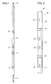
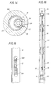
- FIG. 1 shows an embodiment of the RIT 10 of the invention.
- the RIT 10 is an elongated, small-diameter, metal mandrel that may contain one or more antennas 12, sources, sensors [sensor/detector are interchangeable terms as used herein], magnets, a gamma-ray detector/generator assembly, neutron-generating/detecting assembly, various electronics, batteries, a downhole processor, a clock, a read-out port, and recording memory (not shown).
- the RIT 10 does not have the mechanical requirements of a drill collar. Thus, its mechanical constraints are greatly reduced.
- the RIT 10 has a landing mechanism (stinger) 14 on the bottom end and a fishing head 16 on the top.
- the fishing head 16 allows for the RIT 10 to be captured and retrieved from within a sub with the use of a conventional extraction tool such as the one described in U.S. Pat. No. 5,278,550 (assigned to the present assignee).
- An advantage of the fishable RIT 10 assembly is a reduction of Lost-In-Hole costs.
- each antenna 12 on the RIT 10 consists of multi-turn wire loops encased in fiberglass-epoxy 18 mounted in a groove in the RIT 10 pressure housing and sealed with rubber over-molding 20.
- a feed-through 22 provides a passage for the antenna 12 wiring, leading to an inner bore 24 within the RIT 10.
- Each antenna 12 may be activated to receive or transmit an electromagnetic (EM) signal as known in the art.
- EM electromagnetic
- the antennas 12 radiate an azimuthal electric field.
- Each antenna 12 is preferably surrounded by a stainless-steel shield 26 (similar to those described in U.S. Pat. No. 4,949,045, assigned to the present assignee) that has one or more axial slots 28 arrayed around the shield 26 circumference.
- Figure 2b shows the axial slots 28 distributed around the circumference of the shield 26.
- the shields 26 are short-circuited at the axial ends into the metal mandrel body of the RIT 10. These shields 26 permit transverse electric (TE) radiation to propagate through while blocking transverse magnetic (TM) and transverse electromagnetic (TEM) radiation.
- the shields 26 also protect the antennas 12 from external damage.
- the RIT 10 electronics and sensor architecture resembles that described in U.S. Pat. No. 4,899,112 (assigned to the present assignee).
- Figure 3 shows an embodiment of a sub 30 of the invention.
- the sub 30 has an elongated body with tubular walls and a central bore 32.
- the sub 30 contains neither electronics nor sensors and is fully metallic, preferably formed from stainless steel. It is part of the normal bottom hole assembly (BHA), and it is in the hole with the drill string for the duration of the bit run.
- BHA bottom hole assembly
- the sub 30 has normal threaded oilfield connections (pin and box) at each end (not shown).
- the sub 30 includes one or more stations 36 with one or more axial slots 38 placed along the tubular wall.
- Each elongated axial slot 38 fully penetrates the tubular wall of the sub 30 and is preferably formed with fully rounded ends. Stress modeling has shown that rather long slots 38 may be formed in the sub 30 walls while still maintaining the structural integrity of the sub 30. Stress relief grooves 40 may be added to the OD of the sub 30, in regions away from the slot(s) 38, to minimize the bending moment on the slot(s) 38.
- Each slot 38 provides a continuous channel for electromagnetic energy to pass through the sub 30.
- the slots 38 block TM radiation but allow the passage of TE radiation, albeit with some attenuation.
- the degree of attenuation of TE fields by the sub 30 depends on factors such as frequency, the number of slots, slot width, slot length, collar OD and ID, and the location and dimensions of the RIT 10 antenna.
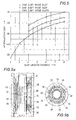
- Figure 5 shows the sub 10 attenuation measured at 400 kHz with a 25-turn 1.75-inch diameter coil centered in 3.55-inch ID, 6.75-inch OD subs 30 with one or two slots 38 of different lengths and widths.
- adding more slots 38 and making the slots longer or wider decreases the attenuation.
- the sub 30 attenuation is already ⁇ 15 dB, which is sufficiently low for many applications.
- the RIT 10 is pumped down and/or lowered through the drillstring on cable at the end of the bit run and engaged inside the sub 30.
- the RIT 10 is received by a landing "shoe" 42 within the central bore 32 of the sub 30, as shown in Figure 4a.
- Figure 4b shows how the RIT 10 is located in the sub 30 so that each antenna 12, source, or sensor is aligned with a slot 38 in the sub 30.
- the landing shoe 42 preferably also has a latching action to prevent any axial motion of the RIT 10 once it is engaged inside the sub 30.
- an embodiment of the invention includes a centralizer 44, which serves to keep the RIT 10 centered and stable within the sub 30, lowering shock levels and reducing the effects of tool motion on the measurement.
- One or more centralizers 44 may be mounted within the central bore 32 to constrain the RIT 10 and keep it from hitting the ID of the sub 30.
- One or more spring-blades 46 may also be mounted to extend from the centralizer 44 to provide positioning stability for the RIT 10. The spring-blades 46 are compressed against the RIT 10 when it is engaged within the sub 30.
- Bolts 48 with O-ring seals 50 may be used to hold the centralizer(s) 44 in the sub 30 while preserving the pressure barrier between the ID and the OD of the sub 30.
- the centralizer 44 may be mounted on the RIT 10 rather than on the sub 30 (See Figure 16). In this case, the centralizer 44 may be configured to remain in a retracted mode during the trip down, and to open when the RIT 10 lands in the sub 30. It will be understood that other centralizer 44 configurations may be implemented with the invention as known in the art.
- the RIT 10 and sub 30 have EM properties similar to a coaxial cable, with the RIT 10 acting as the inner conductor, and the sub 30 acting as the outer conductor of a coaxial cable. If the drilling mud is conductive, then the "coax" is lossy. If the drilling mud is oil based, the "coax" will have little attenuation. Parasitic antenna 12 coupling may take place inside of the sub 30 between receiver-receiver or transmitter-receiver. As described above, the shields 26 surrounding the antennas 12 are grounded to the mandrel of the RIT 10 to minimize capacitive and TEM coupling between them. Electrically balancing the antennas 12 also provides for TEM coupling rejection.
- the centralizers 44 may also be used as a means of contact to provide radio-frequency (rf) short-circuits between the RIT 10 and the sub 30 to prevent parasitic coupling.
- rf radio-frequency
- small wheels with sharp teeth may be mounted on the centralizers 44 to ensure a hard short between the RIT 10 and the sub 30 (not shown).
- an insulating pressure barrier is used to maintain the differential pressure between the inside and the outside of the sub 30 and to maintain hydraulic integrity.
- FIG. 7a an embodiment of a sub 30 with a pressure barrier of the invention is shown.
- a cylindrical sleeve 52 is positioned within the central bore 32 of the sub 30 in alignment with the slot(s) 38.
- the sleeve 52 is formed of a material that provides transparency to EM energy.
- Useable materials include the class of polyetherketones described in U.S. Pat. No. 4,320,224, or other suitable resins. Victrex USA , Inc. of West Chester, PA manufactures one type called PEEK. Another usable compound is known as PEK. Cytec Fiberite, Greene Tweed, and BASF market other suitable thermoplastic resin materials.
- Another useable material is Tetragonal Phase Zirconia ceramic (TZP), manufactured by Coors Ceramics, of Golden, Colorado. It will be appreciated by those skilled in the art that these and other materials may be combined to form a useable sleeve 52.
- ZP Tetragonal Phase Zirconia ceramic
- PEK and PEEK can withstand substantial pressure loading and have been used for harsh downhole conditions. Ceramics can withstand substantially higher loads, but they are not particularly tolerant to shock. Compositions of wound PEEK or PEK and glass, carbon, or KEVLAR may also be used to enhance the strength of the sleeve 52.
- a retainer 54 and spacer 56 are included within the central bore 32 to support the sleeve 52 and provide for displacement and alignment with the slots 38.
- the sleeve 52 is positioned between the retainer 54 and spacer 56, which are formed as hollow cylinders to fit coaxially within the central bore 32. Both are preferably made of stainless steel.
- the retainer 54 is connected to the sleeve 52 at one end, with the sleeve 52 fitting coaxially inside the retainer 54. As the differential pressure increases within the ID of the sub 30 during operation, the sleeve 52 takes the loading, isolating the sub 30 from the pressure in the slotted region. Hydraulic integrity is maintained at the junction between the sleeve 52 and retainer 54 by an O-ring seal 53.
- a fitted "key” 55 is used to engage the sleeve 52 to the retainer 54, preventing one from rotating relative to the other (See Figure 7a blow-up).
- An index pin 57 is fitted through the sub 30 and engaged to the free end of the retainer 54 to prevent the retainer from rotating within the bore 32 of the sub 30.
- O-rings 59 are also placed within grooves on the OD of the retainer 54 to provide a hydraulic seal between the retainer 54 and the sub 30.
- the spacer 56 consists of an inner cylinder 60 within an outer cylinder 62.
- a spring 64 at one end of the OD of the inner cylinder 60 provides an axial force against the outer cylinder 62 (analogous to an automotive shock absorber).
- the outer cylinder 62 is connected to the sleeve 52 using the key 55 and O-ring seal 53 at the junction as described above and shown in the blow-up in Figure 7a.
- the spring-loaded spacer 56 accounts for differential thermal expansion of the components.
- the sub 30 embodiment of Figure 7a is shown connected to other tubular members by threaded oilfield connections 70.
- Figure 7a For purposes of illustration, a sub 30 with only one slot 38 is shown in Figure 7a.
- Other embodiments may include several sleeves 52 interconnected in the described manner to provide individual pressure barriers over multiple slotted stations 36 (not shown). With this configuration, only two O-ring 53 seals to the ID of the sub 30 are used over the entire slotted array section. This minimizes the risk involved with dragging the O-rings 53 over the slots 38 during assembly or repair.
- Figure 7b shows a cross-section of the sub 30 (along line A-A of Figure 7a) with a three-slot 38 configuration.
- Figure 8a shows another embodiment of a sub 30 with a pressure barrier of the invention.
- the spring-loaded spacer 56 maintains the outer cylinder 62 abutted against the sleeve 52 and O-rings 68 are placed within grooves on the OD of the sleeve 52, preferably at both ends of the slot 38.
- the retainer 54 rests at one end against a shoulder or tab 58 formed on the wall of the central bore 32.
- Figure 8b shows a cross-section of the sub 30 (along line B-B of Figure 8a) with a three-slot 38 configuration.
- a sleeve 52 made out of PEEK or PEK, or glass, carbon, or KEVLAR filled versions of these materials may be bonded to a metal insert (not shown), where the insert contains O-rings to seal against the sub 30 as described above.
- the metal insert could be mounted within the sub 30 as described above or with the use of fastener means or locking pins (not shown).
- the sleeve material may also be molded or wrapped onto the supporting insert. The fibers in the wrapped material can also be aligned to provide additional strength.
- Figure 9a shows another embodiment of a pressure barrier of the invention.
- the cylindrical sleeve 52 is held in alignment with the slot(s) 38 by a metal retainer 72.
- the retainer 72 may be formed as a single piece with an appropriate slot 74 cut into it for signal passage as shown, or as independent pieces supporting the sleeve 52 at the top and bottom (not shown).
- the retainer 72 may be constrained from axial movement or rotation within the sub 30 by any of several means known in the art, including an index-pin mechanism or a keyed-jam-nut type arrangement (not shown).
- the slot 38 may also be filled with a protective insert as will be further described below.
- a RIT 10 is positioned within the sub 30 such that the antenna 12 is aligned with the slot(s) 38.
- the retainer 72 is formed such that it extends into and reduces the ID of the sub 30 to constrain the RIT 10. Mudflow occurs through several channels or openings 76 in the retainer 72 and through the annulus 78 between the RIT 10 and the retainer 72.
- the retainer 72 in effect acts as a centralizer to stabilize the RIT 10 and to keep it from hitting the ID of the sub 30, lowering shock levels and increasing reliability.
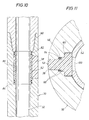
- Figure 10 shows another embodiment of a pressure barrier of the invention.
- a sub 30 may be formed with a shop joint 80 so that the sleeve 52 can be inserted within the central bore 32.
- the sleeve 52 is formed as described above and provides a hydraulic seal using O-rings 82 within grooves at both ends on the OD of the sleeve 52.
- the sleeve 52 is restrained from axial movement within the central bore 32 by a lip 84 formed on one end of the two-piece sub 30 and by the end of the matching sub 30 joint. Since the sleeve 52 sits flush within a recess 86 in the ID of the sub 30, this configuration offers unrestricted passage to a large diameter RIT 10. This configuration also provides easy access to the sleeve 52 and slot(s) 38 for maintenance and inspection.
- FIG 11 another embodiment of a pressure barrier of the invention is shown.
- the slot 38 in the sub 30 is three-stepped, preferably with fully rounded ends.
- One of the steps provides a bearing shoulder 90 for an insert 92, and the other two surfaces form the geometry for an O-ring groove 94 in conjunction with the insert 92.
- a modified O-ring seal consists of an O-ring 96 stretched around the insert 92 at the appropriate step, with metal elements 98 placed on opposite sides of the O-ring 96.
- the metal elements 98 are preferably in the form of closed loops.
- the sleeve 52 may be fitted within the sub 30 with one or more O-rings (not shown) to improve hydraulic integrity as described above. As shown in Figure 11, the sleeve 52 may also have a slot 100 penetrating its wall to provide an unobstructed channel for any incoming or outgoing signal. The sleeve 52 may have a matching slot 100 for every slot 38 in the sub 30.
- the insert 92 and sleeve 52 are preferably made of the dielectric materials described above to permit the passage of EM energy. However, if the sleeve 52 is configured with a slot 100, the sleeve 52 may be formed from any suitable material.
- the sleeve 52 is configured with a slot 100, the internal pressure of the sub 30 may push the insert 92 outward.
- the bearing shoulder 52 takes this load.
- the O-ring 96 pushes the metal elements 98 against an extrusion gap, which effectively closes off the gap.
- the metal is much harder than the O-ring material, it does not extrude at all.
- the modified geometry therefore creates a scenario where a soft element (the O-ring) provides the seal and a hard element (the metal loop) prevents extrusion, which is the ideal seal situation.
- the sleeve 52 captures the insert 92 in the slot 38, preventing the insert 92 from being dislodged.
- pressure barrier configurations may be implemented with the invention.
- One approach is the use of several individual sleeves 52 connected together by other retaining structures and restrained by a pressure-differential seal or a jam-nut arrangement (not shown).
- Another approach is the use of a long sleeve 52 to span multiple slotted stations 38 (not shown).
- Still another approach is the use of a sleeve 52 affixed to the OD of the sub 30 over the slotted region, or a combination of an interior and exterior sleeve 52 (not shown).
- the operational life of the assembly may be extended by preventing debris and fluids from entering and eroding the slots 38 and the insulating sleeve 52.
- the slots 38 could be filled with rubber, an epoxy-fiberglass compound, or another suitable filler material to keep fluids and debris out while permitting signal passage.
- FIG. 12a An embodiment of a sub 30 with a tapered slot 38 is shown in Figure 12a.
- the slot 38 is tapered such that the outer opening W 1 is narrower than the inner opening W 2 , as shown in Figure 12b.
- a tapered wedge 88 of insulating material e.g., fiberglass epoxy
- the wedge 88 may be bonded into the sub 30 with rubber.
- the rubber layer surrounds the wedge 88 and bonds it into the sub 30.
- An annulus of rubber may also be molded on the interior and/or exterior surface of the sub 30 to seal the wedge 88 within the slot 38.
- an antenna 12 consisting of 25 turns of wire on a 1.75-inch diameter bobbin was mounted on a 1-inch diameter metal RIT 10 and positioned fully eccentered radially inside the bore of a 3.55-inch ID, 6.75-inch OD sub 30 against the slot 38 and centered vertically on the slot 38.
- the measured attenuation of the TE field between 25 kHz- 2 MHz was a nearly constant 16.5 dB.
- Figure 14 shows another embodiment of a shielding structure of the invention.
- the central bore 32 of the sub 30 is configured with a bracket structure 106 that serves as a focusing shield by surrounding the antenna 12 when the RIT 10 is engaged within the sub 30.
- FIG 15 shows another embodiment of a shielding structure of the invention.
- the mandrel of the RIT 10 has a machined pocket or cavity 108 in its body.
- a coil antenna 12 wound on a bobbin 110 made of dielectric material is mounted within the cavity 108.
- a ferrite rod may replace the dielectric bobbin 110.
- the hydraulic integrity of the RIT 10 is maintained by potting the antenna 12 with fiberglass-epoxy, rubber, or another suitable substance.
- the attenuation of a coil antenna 12 having 200 turns on a 0.875-inch diameter bobbin was measured for this assembly mounted the same way as described above in the same sub 30. The measured attenuation was only ⁇ 7 dB. It will be appreciated by those skilled in the art that other types of sources/sensors may be housed within the cavity 108 of the RIT 10.
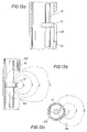
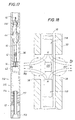
- Figure 16 shows another embodiment of the invention.
- a sub 30 of the invention is connected to another tubular 111 forming a section of a drillstring.
- the RIT 10 includes an antenna 12, a stinger 14 at the lower end, and a fishing head 16 at the top end.
- the stinger 14 is received by the landing shoe 42 on the sub 30, which serves to align the antenna 12 with the slotted station 36.
- the RIT 10 of this embodiment includes various electronics, batteries, a downhole processor, a clock, a read-out port, memory, etc. (not shown) in a pressure housing.
- the RIT 10 may also incorporate various types of sources/sensors as known in the art.
- the RIT 10 of Figure 16 is also equipped with a modulator 116 for signal communication with the surface.
- a useable modulator 116 consists of a rotary valve that operates on a continuous pressure wave in the mud column. By changing the phase of the signal (frequency modulation) and detecting these changes, a signal can be transmitted between the surface and the RIT 10. With this configuration, one can send the RIT 10 through the drillstring to obtain measurement data (e.g., resistivity or gamma-ray counts) of formation characteristics and to communicate such data to the surface in real-time. Alternatively, all or some of the measurement data may be stored downhole in the RIT 10 memory for later retrieval.
- measurement data e.g., resistivity or gamma-ray counts
- the modulator 116 may also be used to verify that the RIT 10 is correctly positioned in the sub 30, and that measurements are functioning properly. It will be appreciated by those skilled in the art that a modulator 116 assembly may be incorporated with all of the RIT/sub implementations of the invention.
- Figure 17 shows another embodiment of the invention.
- the subs 30 and RITs 10 of the invention may be used to communicate data and/or instructions between the surface and a remote tool 112 located along the drill string.
- the tool 112 is shown with a bit box 113 at the bottom portion of a drive shaft 114.
- the drive shaft 114 is connected to a drilling motor 115 via an internal transmission assembly (not shown) and a bearing section 117.
- the tool 112 also has an antenna 12 mounted on the bit box 113.
- the motor 115 rotates the shaft 114, which rotates the bit box 113, thus rotating the antenna 12 during drilling.
- the RIT 10 may be engaged within the sub 30 at the surface or sent through the drill string when the sub 30 is at a desired downhole position. Once engaged, a wireless communication link may be established between the antenna 12 on the RIT 10 and the antenna 12 on the tool 112, with the signal passing through the slotted station 36. In this manner, real-time wireless communication between the surface and the downhole tool 112 may be established. It will be appreciated by those skilled in the art that other types of sensors and/or signal transmitting/receiving devices may be mounted on various types of remote tools 112 for communication with corresponding devices mounted on the RIT 10.
- a determination of formation porosity from magnetic resonance may be obtained with a non-magnetic sub 30 of the invention as shown in Figure 18.
- the sub 30 can be formed of the typical high-strength non-magnetic steel used in the industry.
- the RIT 10 contains the electronics, batteries, CPU, memory, etc., as described above.
- Opposing permanent magnets 118 contained in the RIT 10 provide the magnetic field.
- a rf coil 120 is mounted between the magnets 118 for generating a magnetic field in the same region to excite nuclei of the formation vicinity.
- the design of the rf coil 120 is similar to the antennas 12 described above in being a multi-turn loop antenna with a central tube for through wires and mechanical strength.
- the permanent magnets 118 and rf coil 120 are preferably housed in a non-magnetic section of the sub 30 that has axial slots 38 with a pressure barrier (not shown) of the invention.
- the coil 120 in the RIT 10 provides a rf magnetic field B 1 , which is perpendicular to B 0 outside of the sub 30.
- the rf coil 120 is positioned in alignment with the axial slot(s) 38 in the sub 30.
- a magnetic resonance measurement while tripping may be more complicated in comparison to propagation resistivity measurements due to various factors, including: an inherently lower signal-to-noise ratio, permanent magnet form factors, rf coil efficiency, high Q antenna tuning, high power demands, and a slower logging speed.
- gamma ray transport measurements through a formation can be used to determine its characteristics such as density.
- the interaction of gamma rays by Compton scattering is dependent only upon the number density of the scattering electrons. This in turn is directly proportional to the bulk density of the formation.
- Conventional logging tools have been implemented with detectors and a source of gamma rays whose primary mode of interaction is Compton scattering. See U.S. Pat. No. 5,250,806, assigned to the present assignee.
- Gamma ray formation measurements have also been implemented in LWT technology. See Logging while tripping cuts time to run gamma ray, OIL & GAS JOURNAL, June 1996, pp. 65-66.
- the present invention may be used to obtain gamma-ray measurements as known in the art, providing advantages over known implementations.
- the subs 30 of the invention provide the structural integrity required for drilling operations while also providing a low-density channel for the passage of gamma rays.
- Figure 4b this configuration is used to illustrate a gamma-ray implementation of the invention.
- a RIT 10 is equipped with a gamma-ray source and gamma-ray detectors (not shown) of the type known in the art and described in the '806 patent.
- the antennas 12 of Figure 4b would be replaced with a gamma-ray source and gamma-ray detectors (not shown).
- Two gamma-ray detectors are typically used in this type of measurement.
- the gamma-ray detectors are placed on the RIT 10 at appropriate spacings from the source as known in the art.
- the slotted stations 36 are also appropriately placed to match the source and detector positions of the RIT 10. Calibration of the measurement may be required to account for the rays transmitted along the inside of the sub 30.
- the gamma-ray detectors may also be appropriately housed within the RIT 10 to shield them from direct radiation from the source as known in the art.
- this configuration is used to illustrate another gamma-ray implementation of the invention.
- the RIT 10 equipped with the described gamma-ray assembly and eccentered toward the slots 38, this configuration will capture the scattered gamma rays more efficiently and provide less transmission loss.
- the invention may be used to measure formation resistivity using electromagnetic propagation techniques as known in the art, including those described in U.S. Pats. Nos. 5,594,343 and 4,899,112 (both assigned to the present assignee).
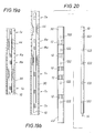
- Figures 19a and 19b show two RIT 10 / sub 30 configurations of the invention.
- a pair of centrally located receiver antennas Rx are used to measure the phase shift and attenuation of EM waves.
- Look-up tables may be used to determine phase shift resistivity and attenuation resistivity.
- Transmitter antennas Tx are placed above and below the receiver antennas Rx, either in the configuration shown in Figure 19a, which has two symmetrically placed transmitter antennas Tx, or in the configuration shown in Figure 19b, which has several transmitter antennas Tx above and below the receiver antennas Rx.
- the architecture of Figure 19a can be used to make a borehole compensated phase-shift and attenuation resistivity measurement, while the multiple Tx spacings of Figure 19b can measure borehole compensated phase-shift and attenuation with multiple depths of investigation. It will be appreciated by those skilled in the art that other source/sensor configurations and algorithms or models may be used to make formation measurements and determine the formation characteristics.
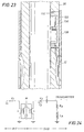
- the sub 30 contains one or more integral antennas 12 mounted on the OD of the elongated body for transmitting and/or receiving electromagnetic energy.
- the antennas 12 are embedded in fiberglass epoxy, with a rubber over-molding as described above.
- the sub 30 also has one or more inductive couplers 122 distributed along its tubular wall.
- the RIT 10 has a small-diameter pressure housing such as the one described above, which contains electronics, batteries, downhole processor, clocks, read-out port, recording memory, etc., and one or more inductive couplers 122 mounted along its body.
- the RIT 10 is eccentered inside the sub 30 so that the inductive coupler(s) 122 in the RIT 10 and the inductive coupler(s) 122 in the sub 30 are in close proximity.
- the couplers 120 consist of windings formed around a ferrite body as known in the art.
- Feed-throughs 124 connect the antenna 12 wires to the inductive coupler 122 located in a small pocket 126 in the sub 30.
- a metal shield 128 with vertical slots covers each antenna 12 to protect it from mechanical damage and provide the desired electromagnetic filtering properties as previously described. Correctly positioning the RIT 10 inside the sub 30 improves the efficiency of the inductive coupling. Positioning is accomplished using a stinger and landing shoe (See Figure 4a) to eccenter the RIT 10 within the sub 30. It will be appreciated by those skilled in the art that other eccentering systems may be used to implement the invention.
- the inductive couplers 122 have "U" shaped cores made of ferrite.
- the ferrite core and windings are potted in fiberglass-epoxy, over molded with rubber 131, and mounted within a coupler package 130 formed of metal.
- the coupler package 130 may be formed of stainless steel or a non-magnetic metal.
- Standard O-ring seals 132 placed around the inductive coupler package 130 provide a hydraulic seal.
- the inductive couplers 122 in the RIT 10 may also be potted in fiberglass-epoxy and over molded with rubber 131.
- a thin cylindrical shield made of PEEK or PEK may also be placed on the OD of the sub 38 to protect and secure the coupler package 130 (not shown).
- the pole faces In operation, there will be a gap between the inductive couplers 122 in the RIT 10 and the sub 30, so the coupling will not be 100% efficient. To improve the coupling efficiency, and to lessen the effects of mis-alignment of the pole faces, it is desirable for the pole faces to have as large a surface area as possible.
- Figure 22b shows a 3.75-inch long by 1-inch wide slot 38 in the sub 30.
- the pole face for this inductive coupler 122 is 1.1-inches long by 0.75-inch wide, giving an overlap area of 0.825 square inches.
- This configuration maintains a high coupling efficiency and reduces the effects due to the following: movement of the RIT 10 during drilling or tripping, variations in the gap between the inductive couplers 122, and variations in the angle of the RIT 10 with respect to the sub 30.
- Another advantage of a long slot 38 design is that it provides space for the pressure feed-throughs 124 in the inductive coupler package 130.
- Antenna tuning elements may also be placed in this package 130 if needed. It will be appreciated by those skilled in the art that other aperture configurations may be formed in the walls of the sub 30 to achieve the desired inductive coupling, such as the circular holes shown in Figure 20.
- the antenna shield 128 can be used to retain the inductive coupler package 130 in place.
- the shield 128 having slots over the antenna 12 as described above, but solid elsewhere.
- the solid portion retains the inductive coupler package 130 and takes the load from the differential pressure drop.
- Tabs may also be placed on the outside of the inductive coupler package 130 to keep it from moving inward (not shown).
- the shield 128 may also be threaded on its ID, with the threads engaging matching "dogs" on the sub 30 (not shown).
- Figure 24 shows a simple circuit model for an embodiment of the inductive coupler and transmitter antenna of the invention.
- the current is I 1
- the voltage is V 1 .
- the current is I 2 and the voltage is V 2 .
- the mutual inductance is M
- the self-inductance of each half is L.
- This inductive coupler is symmetric with the same number of turns on each half.
- the inductive impedance is about 100 ⁇ , while the resistive impedance is about 10 ⁇ .
- the inductive coupler has many turns and a high permeability core, so L>> L A and ⁇ L>>> R A .
- I 2 /I 1 ⁇ -M/L (the sign being relative to the direction of current flow in Figure 24).
- the RIT 10 may be equipped with internal data storage means such as conventional memory and other forms of the kind well known in the art or subsequently developed. These storage means may be used to communicate data and/or instructions between the surface and the downhole RIT 10. Received signal data may be stored downhole within the storage means and subsequently retrieved when the RIT 10 is returned to the surface. As known in the art, a computer (or other recording means) at the surface keeps track of time versus downhole position of the sub so that stored data can be correlated with a downhole location. Alternatively, the signal data and/or instructions may be communicated in real-time between the surface and the RIT 10 by LWD/MWD telemetry as known in the art.
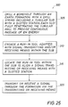
- Figure 25 illustrates a flow diagram of a method 300 for transmitting and/or receiving a signal through an earth formation in accord with the invention.
- the method comprises drilling a borehole through the earth formation with a drill string, the drill string including a sub having an elongated body with tubular walls and including at least one station having at least one slot formed therein, each at least one slot fully penetrating the tubular wall to provide a continuous channel for the passage of electromagnetic energy 305; engaging a run-in tool within the sub, the run-in tool being adapted with signal transmitting means and/or signal receiving means 310; locating the run-in tool within the sub such that at least one signal transmitting or receiving means is aligned with at least one slotted station on the sub 315; and transmitting or receiving a signal through the formation, respectively via the transmitting or receiving means 320.
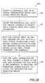
- Figure 26 illustrates a flow diagram of a method 400 for measuring a characteristic of an earth formation surrounding a borehole in accord with the invention.
- the method comprises adapting a downhole tool with at least one signal transmitting means and at least one signal receiving means 405; adapting the downhole tool with end means capable of accepting a fishing head or a cable connection 410; and with the fishing head on the tool, engaging the tool within a drill string to measure the formation characteristic, utilizing the transmitting and receiving means, as the drill string traverses the borehole; with the cable connection on the tool, connecting a cable to the tool and suspending the tool within the borehole to measure the formation characteristic utilizing the transmitting and receiving means 420.
- the method 400 of Figure 26 may be implemented with the run-in tools 10 and subs 30 of the invention.
- the run-in tool may be configured with an end segment or cap (not shown) adapted to receive the previously described fishing head or a cable connection. With the fishing head connected to the run-in tool, the tool may be used in accord with the disclosed implementations. With the cable connection, the run-in tool may be used as a memory-mode wireline tool.
- Figure 27 illustrates a flow diagram of a method 500 for sealing an opening on the surface of a tubular, wherein the tubular has an elongated body with tubular walls and a central bore.
- the method comprises placing an insert within the opening, the insert being formed in the shape of the opening 505; and applying a bonding material to the insert and/or opening to bond the insert within the opening 510.
- Figure 28 illustrates a flow diagram of a method 600 for sealing a fully penetrating opening on the surface of a tubular having an elongated body with tubular walls and a central bore.
- the method comprises placing an insert within the opening, the insert being formed in the shape of the opening 605, and placing retainer means within the tubular to support the insert against the opening 610.
Abstract
Description
Claims (38)
- A downhole tubular (30), characterized byan elongated body with tubular walls and a central bore (32), the body including at least one slot (38) formed therein such that the slot fully penetrates the tubular wall; andmeans to provide a pressure barrier between the interior and exterior of the tubular wall, the means located within the central bore in alignment with the at least one slot.
- The downhole tubular (30) of claim 1, wherein the means to provide a pressure barrier comprises a sleeve (52) formed of a material providing transparency to electromagnetic energy.
- The downhole tubular (30) of claim 1, further characterized by at least one spacer (56) disposed within the central bore and adapted with spring means (64) to allow for displacement of the pressure barrier means.
- The downhole tubular (30) of claim 1, further characterized by means for receiving a run-in tool (10) within the central bore (32).
- The downhole tubular (30) of claim 4, further characterized by at least one centralizer (44) within the central bore (32) to constrain the movement of the run-in tool (10) when the tool is located within the tubular.
- The downhole tubular (30) of claim 4, wherein the run-in tool (10) comprises at least one centralizer (44) to constrain the movement of the run-in tool when the tool is located within the tubular.
- The downhole tubular (30) of claim 1, further characterized by a retainer (54) disposed within the central bore (32) to maintain the pressure barrier means in alignment with the at least one slot (38).
- The downhole tubular (30) of claim 7, wherein the retainer (54) is formed such that it reduces the inside diameter of the sub.
- The downhole tubular (30) of claim 8, wherein the body of the retainer (54) comprises passage means to allow for the passage of fluids through the retainer body.
- The downhole tubular (30) defined by any of claims 1 to 9, wherein the elongated body includes connecting means (70) at each end thereof, the connecting means adapted for connection to other tubular members.
- The downhole tubular (30) defined by any of claims 1 to 10, wherein the tubular section including the at least one slot (38) is formed of a non-magnetic material.
- The downhole tubular (30) defined by any of claims 1 to 11, wherein the at least one slot (38) comprises an insert or filler material.
- The downhole tubular (30) defined by any of claims 1 to 12, wherein the walls of the elongated body are fully metallic.
- A system for receiving a run-in tool (10), comprising:a sub (30) having an elongated body with tubular walls and a central bore (32), the sub being adapted to form a portion of a length of drill string, characterized bythe sub including at least one station having at least one slot (38) formed therein such that the slot fully penetrates the tubular wall to provide a continuous channel for the passage of a signal;the run-in tool being adapted for transit through the drill string and into the central bore of the sub; andmeans for receiving (42) the run-in tool within the sub.
- The system of claim 14, wherein the at least one slotted station includes means to provide a pressure barrier between the interior and exterior of the tubular wall.
- The system of claim 15, wherein the means to provide a pressure barrier includes a sleeve (52) positioned in alignment with the slotted station.
- The system of claim 14, wherein the run-in tool (10) includes connecting means (16) at one end thereof, the connecting means adapted to allow for retrieval of the tool from within the bore (32) of the sub.
- The system of claim 14, wherein the run-in tool (10) comprises permanent magnet means (118).
- The system of claim 14, wherein the run-in tool (10) comprises at least one antenna (12) adapted to transmit and/or receive electromagnetic energy.
- The system of claim 19, wherein the receiving means (42) is adapted to locate the run-in tool (10) within the bore (32) such that at least one antenna (12) on the tool is aligned with a slotted station on the sub (30).
- The system of claim 14, wherein the run-in tool (10) comprises one of a gamma-ray source or a neutron source.
- The system defined by any of claims 14 to 21, wherein the walls of the elongated sub body (30) are fully metallic.
- A system for receiving a run-in tool (10), comprising:a sub (30) having an elongated body with tubular walls and a central bore (32), the sub being adapted to form a portion of a length of drill string, characterized bythe sub including at least one inductive coupling means (122) disposed thereon;the sub including at least one signal source or sensor disposed thereon;the run-in tool including at least one inductive coupling means disposed thereon;the run-in tool being adapted for transit through the drill string and into the central bore of the sub; andmeans for receiving (42) the run-in tool within the sub.
- The system of claim 23, wherein the receiving means (42) is adapted to eccenter the run-in tool (10) within the bore (32) when the tool is located within the bore.
- The system of claim 23, wherein the at least one inductive coupling means (122) disposed on the sub (30) is electrically connected to at least one signal source or sensor on the sub.
- The system of claim 23, wherein the at least one signal source is adapted to transmit electromagnetic energy and the at least one sensor is adapted to receive electromagnetic energy.
- A method for transmitting and/or receiving a signal through an earth formation, characterized bya) drilling a borehole through the earth formation with a drill string, the drill string including a sub (30) having an elongated body with tubular walls and including at least one station having at least one slot (38) formed therein, each at least one slot fully penetrating the tubular wall to provide a continuous channel for the passage of a signal;b) engaging a run-in tool (10) within the sub, the run-in tool being adapted with signal transmitting means and/or signal receiving means;c) locating the run-in tool within the sub such that at least one signal transmitting or receiving means is aligned with at least one slotted station on the sub; andd) transmitting or receiving a signal through the formation, respectively via the transmitting or receiving means.
- The method of claim 27, wherein the signal transmitting means are adapted to transmit electromagnetic energy and the signal receiving means are adapted to receive electromagnetic energy.
- The method of claim 28, further characterized by relating the received electromagnetic energy to formation resistivity.
- A method for measuring a characteristic of an earth formation surrounding a borehole, comprising:a) adapting a downhole tool (10) with at least one signal transmitting means and at least one signal receiving means, characterized byb) adapting the downhole tool with end means capable of accepting a fishing head or a cable connection; andc) with the fishing head on the tool, engaging the tool within a drill string to measure the formation characteristic utilizing the transmitting and receiving means; ord) with the cable connection on the tool, connecting a cable to the tool and suspending the tool within the borehole to measure the formation characteristic utilizing the transmitting and receiving means.
- The method of claim 30, wherein step (c) comprises engaging the tool (10) within a sub (30) on the drill string, wherein the sub has an elongated body with tubular walls and includes at least one station having at least one slot (38) formed therein such that the slot fully penetrates the tubular wall to provide a continuous channel for the passage of a signal.
- A method for sealing a fully penetrating opening (38) on a tubular (30), the tubular having an elongated body with tubular walls and a central bore (32) adapted for fluid passage, characterized bya) placing an insert (88, 92) within the opening, the insert being formed in the shape of the opening; andb) applying a bonding material to the insert and/or opening to bond the insert within the opening.
- The method of claim 32, further characterized by placing a cylindrical sleeve within the central bore or around the outer surface of the tubular (30) in alignment with the opening.
- The method of any claim 32, further characterized by placing a metallic shield around the outer surface of the tubular (30) in alignment with the opening (38) to restrain the insert (88, 92).
- A method for sealing a fully penetrating opening (38) on a tubular (30), the tubular having an elongated body with tubular walls and a central bore (32),
characterized bya) placing an insert (88, 92) within the opening, the insert being formed in the shape of the opening, andb) placing retainer means within the tubular to support the insert against the opening. - The method of claim 35, wherein the retainer means comprises a sleeve (52) positioned coaxially within the central bore (32) of the tubular (30).
- The method of claim 35, wherein step (a) comprises placing the insert (88, 92) within the opening (38) from within the central bore (32) outward.
- The method defined by any of claims 35 to 37, wherein the insert (88, 92) is formed of a material providing transparency to electromagnetic energy.
Applications Claiming Priority (2)
| Application Number | Priority Date | Filing Date | Title |
|---|---|---|---|
| US576271 | 1995-12-21 | ||
| US09/576,271 US6577244B1 (en) | 2000-05-22 | 2000-05-22 | Method and apparatus for downhole signal communication and measurement through a metal tubular |
Publications (3)
| Publication Number | Publication Date |
|---|---|
| EP1158138A2 true EP1158138A2 (en) | 2001-11-28 |
| EP1158138A3 EP1158138A3 (en) | 2004-03-17 |
| EP1158138B1 EP1158138B1 (en) | 2009-12-09 |
Family
ID=24303679
Family Applications (1)
| Application Number | Title | Priority Date | Filing Date |
|---|---|---|---|
| EP01201810A Expired - Lifetime EP1158138B1 (en) | 2000-05-22 | 2001-05-15 | Downhole signal communication and measurement through a metal tubular |
Country Status (6)
| Country | Link |
|---|---|
| US (6) | US6577244B1 (en) |
| EP (1) | EP1158138B1 (en) |
| CA (1) | CA2346546C (en) |
| DE (1) | DE60140714D1 (en) |
| DK (1) | DK1158138T3 (en) |
| NO (2) | NO321737B1 (en) |
Cited By (27)
| Publication number | Priority date | Publication date | Assignee | Title |
|---|---|---|---|---|
| GB2375779A (en) * | 2001-03-23 | 2002-11-27 | Schlumberger Holdings | Inductive coupler for a wired pipe joint |
| US6641434B2 (en) | 2001-06-14 | 2003-11-04 | Schlumberger Technology Corporation | Wired pipe joint with current-loop inductive couplers |
| GB2395503A (en) * | 2002-11-25 | 2004-05-26 | Schlumberger Holdings | Logging while tripping with a modified tubular |
| GB2406347A (en) * | 2002-11-25 | 2005-03-30 | Schlumberger Holdings | Logging while tripping with a modified tubular |
| US6950034B2 (en) | 2003-08-29 | 2005-09-27 | Schlumberger Technology Corporation | Method and apparatus for performing diagnostics on a downhole communication system |
| US6995500B2 (en) | 2003-07-03 | 2006-02-07 | Pathfinder Energy Services, Inc. | Composite backing layer for a downhole acoustic sensor |
| US7036363B2 (en) | 2003-07-03 | 2006-05-02 | Pathfinder Energy Services, Inc. | Acoustic sensor for downhole measurement tool |
| US7040415B2 (en) | 2003-10-22 | 2006-05-09 | Schlumberger Technology Corporation | Downhole telemetry system and method |
| US7075215B2 (en) | 2003-07-03 | 2006-07-11 | Pathfinder Energy Services, Inc. | Matching layer assembly for a downhole acoustic sensor |
| US7096961B2 (en) | 2003-04-29 | 2006-08-29 | Schlumberger Technology Corporation | Method and apparatus for performing diagnostics in a wellbore operation |
| CN101353961A (en) * | 2007-07-26 | 2009-01-28 | 普拉德研究及开发股份有限公司 | Well bore logging detector and manufacture method thereof |
| CN100458101C (en) * | 2003-08-07 | 2009-02-04 | 施卢默格海外有限公司 | Retrievable subsurface nuclear logging system |
| US8056619B2 (en) | 2006-03-30 | 2011-11-15 | Schlumberger Technology Corporation | Aligning inductive couplers in a well |
| EP2248994A3 (en) * | 2009-05-04 | 2012-01-04 | Services Pétroliers Schlumberger | Logging tool having shielded triaxial antennas |
| US8117907B2 (en) | 2008-12-19 | 2012-02-21 | Pathfinder Energy Services, Inc. | Caliper logging using circumferentially spaced and/or angled transducer elements |
| US8235127B2 (en) | 2006-03-30 | 2012-08-07 | Schlumberger Technology Corporation | Communicating electrical energy with an electrical device in a well |
| RU2473100C2 (en) * | 2007-08-10 | 2013-01-20 | Шлюмбергер Текнолоджи Б.В. | High-strength neutron shield |
| US8839850B2 (en) | 2009-10-07 | 2014-09-23 | Schlumberger Technology Corporation | Active integrated completion installation system and method |
| US9134449B2 (en) | 2009-05-04 | 2015-09-15 | Schlumberger Technology Corporation | Directional resistivity measurement for well placement and formation evaluation |
| US9170341B2 (en) | 2011-09-30 | 2015-10-27 | Johnson Matthey Public Limited Company | Flame-proof radiation detector with wireless communication means |
| US9175560B2 (en) | 2012-01-26 | 2015-11-03 | Schlumberger Technology Corporation | Providing coupler portions along a structure |
| US9249559B2 (en) | 2011-10-04 | 2016-02-02 | Schlumberger Technology Corporation | Providing equipment in lateral branches of a well |
| US9644476B2 (en) | 2012-01-23 | 2017-05-09 | Schlumberger Technology Corporation | Structures having cavities containing coupler portions |
| US9938823B2 (en) | 2012-02-15 | 2018-04-10 | Schlumberger Technology Corporation | Communicating power and data to a component in a well |
| US10036234B2 (en) | 2012-06-08 | 2018-07-31 | Schlumberger Technology Corporation | Lateral wellbore completion apparatus and method |
| US10371781B2 (en) | 2009-05-04 | 2019-08-06 | Schlumberger Technology Corporation | Gain-corrected measurements |
| WO2021174025A1 (en) * | 2020-02-27 | 2021-09-02 | Baker Hughes Oilfield Operations Llc | Signal-transparent tubular for downhole operations |
Families Citing this family (163)
| Publication number | Priority date | Publication date | Assignee | Title |
|---|---|---|---|---|
| US20040239521A1 (en) | 2001-12-21 | 2004-12-02 | Zierolf Joseph A. | Method and apparatus for determining position in a pipe |
| US7283061B1 (en) * | 1998-08-28 | 2007-10-16 | Marathon Oil Company | Method and system for performing operations and for improving production in wells |
| US6736210B2 (en) * | 2001-02-06 | 2004-05-18 | Weatherford/Lamb, Inc. | Apparatus and methods for placing downhole tools in a wellbore |
| US6577244B1 (en) * | 2000-05-22 | 2003-06-10 | Schlumberger Technology Corporation | Method and apparatus for downhole signal communication and measurement through a metal tubular |
| US6836218B2 (en) * | 2000-05-22 | 2004-12-28 | Schlumberger Technology Corporation | Modified tubular equipped with a tilted or transverse magnetic dipole for downhole logging |
| US7014100B2 (en) | 2001-04-27 | 2006-03-21 | Marathon Oil Company | Process and assembly for identifying and tracking assets |
| US20030001753A1 (en) * | 2001-06-29 | 2003-01-02 | Cernocky Edward Paul | Method and apparatus for wireless transmission down a well |
| US20030000411A1 (en) * | 2001-06-29 | 2003-01-02 | Cernocky Edward Paul | Method and apparatus for detonating an explosive charge |
| US6838876B2 (en) * | 2002-02-18 | 2005-01-04 | Baker Hughes Incorporated | Slotted NMR antenna cover |
| US7696901B2 (en) * | 2002-03-22 | 2010-04-13 | Schlumberger Technology Corporation | Methods and apparatus for photonic power conversion downhole |
| US7894297B2 (en) * | 2002-03-22 | 2011-02-22 | Schlumberger Technology Corporation | Methods and apparatus for borehole sensing including downhole tension sensing |
| US7187620B2 (en) * | 2002-03-22 | 2007-03-06 | Schlumberger Technology Corporation | Method and apparatus for borehole sensing |
| US7007756B2 (en) * | 2002-11-22 | 2006-03-07 | Schlumberger Technology Corporation | Providing electrical isolation for a downhole device |
| US6962202B2 (en) * | 2003-01-09 | 2005-11-08 | Shell Oil Company | Casing conveyed well perforating apparatus and method |
| CA2539212C (en) * | 2003-02-25 | 2011-05-24 | General Oil Tools, Lp | Method and apparatus to complete a well having tubing inserted through a valve |
| US7513147B2 (en) * | 2003-07-03 | 2009-04-07 | Pathfinder Energy Services, Inc. | Piezocomposite transducer for a downhole measurement tool |
| US7178607B2 (en) | 2003-07-25 | 2007-02-20 | Schlumberger Technology Corporation | While drilling system and method |
| US7073378B2 (en) * | 2003-08-07 | 2006-07-11 | Schlumberger Technology Corporation | Integrated logging tool for borehole |
| US7063148B2 (en) * | 2003-12-01 | 2006-06-20 | Marathon Oil Company | Method and system for transmitting signals through a metal tubular |
| US7046112B2 (en) * | 2004-01-26 | 2006-05-16 | Halliburton Energy Services, Inc. | Logging tool induction coil form |
| US7647987B2 (en) * | 2004-02-26 | 2010-01-19 | The Charles Machine Works, Inc. | Multiple antenna system for horizontal directional drilling |
| US7063134B2 (en) * | 2004-06-24 | 2006-06-20 | Tenneco Automotive Operating Company Inc. | Combined muffler/heat exchanger |
| US7248177B2 (en) * | 2004-06-28 | 2007-07-24 | Intelliserv, Inc. | Down hole transmission system |
| US7319410B2 (en) * | 2004-06-28 | 2008-01-15 | Intelliserv, Inc. | Downhole transmission system |
| US7140434B2 (en) | 2004-07-08 | 2006-11-28 | Schlumberger Technology Corporation | Sensor system |
| US7168510B2 (en) * | 2004-10-27 | 2007-01-30 | Schlumberger Technology Corporation | Electrical transmission apparatus through rotating tubular members |
| GB0426594D0 (en) * | 2004-12-03 | 2005-01-05 | Expro North Sea Ltd | Downhole communication |
| US7652845B2 (en) * | 2005-02-23 | 2010-01-26 | Seagate Technology Llc | Stress relief features for an overmolded base |
| US20060214814A1 (en) * | 2005-03-24 | 2006-09-28 | Schlumberger Technology Corporation | Wellbore communication system |
| GB2469954A (en) * | 2005-05-10 | 2010-11-03 | Baker Hughes Inc | Telemetry Apparatus for wellbore operations |
| US7546885B2 (en) * | 2005-05-19 | 2009-06-16 | Schlumberger Technology Corporation | Apparatus and method for obtaining downhole samples |
| US7671597B2 (en) * | 2005-06-14 | 2010-03-02 | Schlumberger Technology Corporation | Composite encased tool for subsurface measurements |
| US20070131412A1 (en) * | 2005-06-14 | 2007-06-14 | Schlumberger Technology Corporation | Mass Isolation Joint for Electrically Isolating a Downhole Tool |
| US8004421B2 (en) * | 2006-05-10 | 2011-08-23 | Schlumberger Technology Corporation | Wellbore telemetry and noise cancellation systems and method for the same |
| US7495446B2 (en) * | 2005-08-23 | 2009-02-24 | Schlumberger Technology Corporation | Formation evaluation system and method |
| US7477162B2 (en) * | 2005-10-11 | 2009-01-13 | Schlumberger Technology Corporation | Wireless electromagnetic telemetry system and method for bottomhole assembly |
| US7836973B2 (en) * | 2005-10-20 | 2010-11-23 | Weatherford/Lamb, Inc. | Annulus pressure control drilling systems and methods |
| US7377315B2 (en) * | 2005-11-29 | 2008-05-27 | Hall David R | Complaint covering of a downhole component |
| US7712524B2 (en) | 2006-03-30 | 2010-05-11 | Schlumberger Technology Corporation | Measuring a characteristic of a well proximate a region to be gravel packed |
| US20080001775A1 (en) * | 2006-06-30 | 2008-01-03 | Baker Hughes Incorporated | Apparatus and method for memory dump and/or communication for mwd/lwd tools |
| US7605715B2 (en) * | 2006-07-10 | 2009-10-20 | Schlumberger Technology Corporation | Electromagnetic wellbore telemetry system for tubular strings |
| US7557492B2 (en) * | 2006-07-24 | 2009-07-07 | Halliburton Energy Services, Inc. | Thermal expansion matching for acoustic telemetry system |
| US7595737B2 (en) * | 2006-07-24 | 2009-09-29 | Halliburton Energy Services, Inc. | Shear coupled acoustic telemetry system |
| US9024776B2 (en) * | 2006-09-15 | 2015-05-05 | Schlumberger Technology Corporation | Methods and systems for wellhole logging utilizing radio frequency communication |
| US7554328B2 (en) * | 2006-11-13 | 2009-06-30 | Baker Hughes Incorporated | Method and apparatus for reducing borehole and eccentricity effects in multicomponent induction logging |
| US20080224706A1 (en) | 2006-11-13 | 2008-09-18 | Baker Hughes Incorporated | Use of Electrodes and Multi-Frequency Focusing to Correct Eccentricity and Misalignment Effects on Transversal Induction Measurements |
| DE602006010226D1 (en) * | 2006-12-21 | 2009-12-17 | Schlumberger Technology Bv | 2D borehole test with smart plug sensors |
| US7782060B2 (en) * | 2006-12-28 | 2010-08-24 | Schlumberger Technology Corporation | Integrated electrode resistivity and EM telemetry tool |
| US8031081B2 (en) * | 2006-12-28 | 2011-10-04 | Schlumberger Technology Corporation | Wireless telemetry between wellbore tools |
| US7587936B2 (en) * | 2007-02-01 | 2009-09-15 | Smith International Inc. | Apparatus and method for determining drilling fluid acoustic properties |
| US7598742B2 (en) * | 2007-04-27 | 2009-10-06 | Snyder Jr Harold L | Externally guided and directed field induction resistivity tool |
| US8436618B2 (en) | 2007-02-19 | 2013-05-07 | Schlumberger Technology Corporation | Magnetic field deflector in an induction resistivity tool |
| US8395388B2 (en) | 2007-02-19 | 2013-03-12 | Schlumberger Technology Corporation | Circumferentially spaced magnetic field generating devices |
| US7994791B2 (en) * | 2007-02-19 | 2011-08-09 | Schlumberger Technology Corporation | Resistivity receiver spacing |
| US8198898B2 (en) | 2007-02-19 | 2012-06-12 | Schlumberger Technology Corporation | Downhole removable cage with circumferentially disposed instruments |
| US20080202742A1 (en) * | 2007-02-27 | 2008-08-28 | Hall David R | Open Cavity in a Pocket of a Downhole Tool String Component |
| US8082990B2 (en) * | 2007-03-19 | 2011-12-27 | Schlumberger Technology Corporation | Method and system for placing sensor arrays and control assemblies in a completion |
| US7896196B2 (en) | 2007-06-27 | 2011-03-01 | Joseph S. Kanfer | Fluid dispenser having infrared user sensor |
| US8631881B2 (en) * | 2007-07-19 | 2014-01-21 | Neos Inc. | Inserting and extracting underground sensors |
| US8244473B2 (en) * | 2007-07-30 | 2012-08-14 | Schlumberger Technology Corporation | System and method for automated data analysis and parameter selection |
| US7723989B2 (en) * | 2007-08-31 | 2010-05-25 | Schlumberger Technology Corporation | Transducer assemblies for subsurface use |
| WO2009042494A2 (en) * | 2007-09-27 | 2009-04-02 | Schlumberger Canada Limited | Modular power source for subsurface systems |
| US7902955B2 (en) * | 2007-10-02 | 2011-03-08 | Schlumberger Technology Corporation | Providing an inductive coupler assembly having discrete ferromagnetic segments |
| US20090151935A1 (en) * | 2007-12-13 | 2009-06-18 | Schlumberger Technology Corporation | System and method for detecting movement in well equipment |
| US20090151939A1 (en) * | 2007-12-13 | 2009-06-18 | Schlumberger Technology Corporation | Surface tagging system with wired tubulars |
| US8172007B2 (en) * | 2007-12-13 | 2012-05-08 | Intelliserv, LLC. | System and method of monitoring flow in a wellbore |
| US9194227B2 (en) | 2008-03-07 | 2015-11-24 | Marathon Oil Company | Systems, assemblies and processes for controlling tools in a wellbore |
| US10119377B2 (en) | 2008-03-07 | 2018-11-06 | Weatherford Technology Holdings, Llc | Systems, assemblies and processes for controlling tools in a well bore |
| EP2484857A3 (en) * | 2008-03-19 | 2016-08-10 | Services Pétroliers Schlumberger | Method and apparatus for performing wireline logging operations in an under-balanced well |
| WO2009142957A1 (en) * | 2008-05-20 | 2009-11-26 | Schlumberger Canada Limited | System to perforate a cemented liner having lines or tools outside the liner |
| US8312320B2 (en) * | 2008-08-25 | 2012-11-13 | Saudi Arabian Oil Company | Intelligent field oil and gas field data acquisition, delivery, control, and retention based apparatus, program product and related methods |
| US8046170B2 (en) * | 2008-09-03 | 2011-10-25 | Baker Hughes Incorporated | Apparatus and method for estimating eccentricity effects in resistivity measurements |
| US8035392B2 (en) * | 2008-10-17 | 2011-10-11 | Baker Hughes Incorporated | Method and apparatus for while-drilling transient resistivity measurements |
| US20100219835A1 (en) * | 2008-12-10 | 2010-09-02 | Wentworth Steven W | Non-magnetic transmitter housing |
| US7897915B2 (en) * | 2008-12-19 | 2011-03-01 | Schlumberger Technology Corporation | Segmented tubular body |
| US8006769B2 (en) | 2009-02-13 | 2011-08-30 | Specialty Supply Companies | Shearing tool and methods of use |
| US8049506B2 (en) | 2009-02-26 | 2011-11-01 | Aquatic Company | Wired pipe with wireless joint transceiver |
| US8469084B2 (en) * | 2009-07-15 | 2013-06-25 | Schlumberger Technology Corporation | Wireless transfer of power and data between a mother wellbore and a lateral wellbore |
| EP2456948B1 (en) * | 2009-07-23 | 2017-10-25 | Baker Hughes Incorporated | Wired conduit segment and method of making same |
| DE102010017738A1 (en) * | 2009-11-08 | 2011-08-04 | Eichelhardter Werkzeug- und Maschinenbau GmbH, 57612 | Connecting arrangement for connecting a mower blade drive with a mower blade |
| US8091627B2 (en) * | 2009-11-23 | 2012-01-10 | Hall David R | Stress relief in a pocket of a downhole tool string component |
| US20110080806A1 (en) * | 2009-12-08 | 2011-04-07 | Randy Allen Normann | System and method for geothermal acoustic interface |
| US9588250B2 (en) | 2010-04-14 | 2017-03-07 | Baker Hughes Incorporated | Three-coil system with short nonconductive inserts for transient MWD resistivity measurements |
| US8850899B2 (en) | 2010-04-15 | 2014-10-07 | Marathon Oil Company | Production logging processes and systems |
| WO2011163602A2 (en) * | 2010-06-24 | 2011-12-29 | Schlumberger Canada Limited | Systems and methods for collecting one or more measurements in a borehole |
| US20140083177A1 (en) * | 2011-02-28 | 2014-03-27 | Schlumberger Technology Corporation | System For Logging While Running Casing |
| EP2774157B1 (en) * | 2011-11-01 | 2021-09-08 | Norgren GmbH | Solenoid with an over-molded component |
| WO2013133860A2 (en) | 2012-03-09 | 2013-09-12 | Halliburton Energy Services, Inc. | Method and assembly for conveying well logging tools |
| US9016367B2 (en) | 2012-07-19 | 2015-04-28 | Harris Corporation | RF antenna assembly including dual-wall conductor and related methods |
| US20140083773A1 (en) * | 2012-09-26 | 2014-03-27 | Nabors International, Inc. | Reliability for Electromagnetic Data Telemetry for Downhole Application on Well Drilling Operations |
| US9863237B2 (en) * | 2012-11-26 | 2018-01-09 | Baker Hughes, A Ge Company, Llc | Electromagnetic telemetry apparatus and methods for use in wellbore applications |
| US9157304B2 (en) | 2012-12-03 | 2015-10-13 | Harris Corporation | Hydrocarbon resource recovery system including RF transmission line extending alongside a well pipe in a wellbore and related methods |
| US9057241B2 (en) | 2012-12-03 | 2015-06-16 | Harris Corporation | Hydrocarbon resource recovery system including different hydrocarbon resource recovery capacities and related methods |
| EP2929138B1 (en) * | 2012-12-07 | 2019-09-18 | Evolution Engineering Inc. | Methods and apparatus for downhole probes |
| WO2014105007A1 (en) * | 2012-12-26 | 2014-07-03 | Halliburton Energy Services, Inc. | Method and assembly for determining landing of logging tools in a wellbore |
| NO20130595A1 (en) * | 2013-04-30 | 2014-10-31 | Sensor Developments As | A connectivity system for a permanent borehole system |
| US9213124B2 (en) * | 2013-03-22 | 2015-12-15 | Oliden Technology, Llc | Restorable antennae apparatus and system for well logging |
| US9303464B2 (en) | 2013-03-26 | 2016-04-05 | Baker Hughes Incorporated | Wired pipe coupler connector |
| WO2014171952A1 (en) | 2013-04-19 | 2014-10-23 | Halliburton Energy Services, Inc. | Fluid flow during landing of logging tools in bottom hole assembly |
| US10006280B2 (en) | 2013-05-31 | 2018-06-26 | Evolution Engineering Inc. | Downhole pocket electronics |
| WO2014205006A1 (en) | 2013-06-18 | 2014-12-24 | Well Resolutions Technology | Modular resistivity sensor for downhole measurement while drilling |
| WO2014205130A2 (en) | 2013-06-18 | 2014-12-24 | Well Resolutions Technology | Apparatus and methods for communicating downhole data |
| US9631446B2 (en) | 2013-06-26 | 2017-04-25 | Impact Selector International, Llc | Impact sensing during jarring operations |
| US9964660B2 (en) | 2013-07-15 | 2018-05-08 | Baker Hughes, A Ge Company, Llc | Electromagnetic telemetry apparatus and methods for use in wellbores |
| US9575202B2 (en) | 2013-08-23 | 2017-02-21 | Baker Hughes Incorporated | Methods and devices for extra-deep azimuthal resistivity measurements |
| US20150218938A1 (en) * | 2014-01-31 | 2015-08-06 | Weatherford/Lamb, Inc. | Hard-Mounted EM Telemetry System for MWD Tool in Bottom Hole Assembly |
| CA2947008C (en) | 2014-05-01 | 2020-06-30 | Halliburton Energy Services, Inc. | Guided drilling methods and systems employing a casing segment with at least one transmission crossover arrangement |
| US10358909B2 (en) | 2014-05-01 | 2019-07-23 | Halliburton Energy Services, Inc. | Interwell tomography methods and systems employing a casing segment with at least one transmission crossover arrangement |
| US10309215B2 (en) * | 2014-05-01 | 2019-06-04 | Halliburton Energy Services, Inc. | Casing segment having at least one transmission crossover arrangement |
| CA2946147C (en) | 2014-05-01 | 2020-02-11 | Scientific Drilling International, Inc. | Plug for downhole logging tool |
| WO2015167935A1 (en) | 2014-05-01 | 2015-11-05 | Halliburton Energy Services, Inc. | Multilateral production control methods and systems employing a casing segment with at least one transmission crossover arrangement |
| WO2015171122A1 (en) * | 2014-05-06 | 2015-11-12 | Sharewell Energy Services, LLC | Orienting hanger assembly for deploying mwd tools |
| US9435166B2 (en) | 2014-05-06 | 2016-09-06 | Ge Energy Oilfield Technology, Inc. | Method for aligning MWD tool using orienting hanger assembly |
| US9453406B2 (en) | 2014-05-06 | 2016-09-27 | Ge Energy Oilfield Technology, Inc. | Orienting hanger assembly for deploying MWD tools |
| US20150361757A1 (en) * | 2014-06-17 | 2015-12-17 | Baker Hughes Incoporated | Borehole shut-in system with pressure interrogation for non-penetrated borehole barriers |
| US10024992B2 (en) | 2014-08-08 | 2018-07-17 | Halliburton Energy Services, Inc. | Structural element for sonic tools and acoustic isolators |
| GB2546217B (en) | 2014-12-18 | 2020-10-14 | Halliburton Energy Services Inc | High-efficiency downhole wireless communication |
| CN107075943A (en) | 2014-12-29 | 2017-08-18 | 哈利伯顿能源服务公司 | The band gap transceiver of electromagnetic coupled |
| CA2968683C (en) | 2015-02-19 | 2019-11-26 | Halliburton Energy Services, Inc. | Gamma detection sensors in a rotary steerable tool |
| US9951602B2 (en) | 2015-03-05 | 2018-04-24 | Impact Selector International, Llc | Impact sensing during jarring operations |
| CN106194153B (en) * | 2015-05-06 | 2019-06-11 | 中国石油天然气股份有限公司 | Cross drilling tool logging method and system |
| US9768546B2 (en) | 2015-06-11 | 2017-09-19 | Baker Hughes Incorporated | Wired pipe coupler connector |
| US10519767B2 (en) * | 2015-07-29 | 2019-12-31 | Baker Hughes, A Ge Company, Llc | Adaptive shell module with embedded functionality |
| US10612373B2 (en) * | 2015-08-28 | 2020-04-07 | Halliburton Energy Services, Inc. | Add-on antennas for extending electromagnetic measurement range downhole |
| WO2017048506A1 (en) * | 2015-09-15 | 2017-03-23 | Schlumberger Technology Corporation | Antenna for a logging-while-drilling tool |
| US10210976B2 (en) * | 2015-11-30 | 2019-02-19 | Schlumberger Technology Corporation | Magnetic casing clamping system |
| US10254430B2 (en) * | 2016-03-17 | 2019-04-09 | Baker Hughes, A Ge Company, Llc | Downhole deep transient measurements with improved sensors |
| US9869176B2 (en) * | 2016-04-07 | 2018-01-16 | Tubel Energy, Llc | Downhole to surface data lift apparatus |
| CA3020022A1 (en) | 2016-04-13 | 2017-10-19 | Acceleware Ltd. | Apparatus and methods for electromagnetic heating of hydrocarbon formations |
| GB2568612A (en) * | 2016-08-15 | 2019-05-22 | Sanvean Tech Llc | Drilling dynamics data recorder |
| WO2018123263A1 (en) * | 2016-12-28 | 2018-07-05 | ソニーセミコンダクタソリューションズ株式会社 | Antenna device, communication device, and communication method |
| US10316619B2 (en) | 2017-03-16 | 2019-06-11 | Saudi Arabian Oil Company | Systems and methods for stage cementing |
| US10544648B2 (en) | 2017-04-12 | 2020-01-28 | Saudi Arabian Oil Company | Systems and methods for sealing a wellbore |
| US10557330B2 (en) | 2017-04-24 | 2020-02-11 | Saudi Arabian Oil Company | Interchangeable wellbore cleaning modules |
| US11506024B2 (en) | 2017-06-01 | 2022-11-22 | Halliburton Energy Services, Inc. | Energy transfer mechanism for wellbore junction assembly |
| US11261708B2 (en) | 2017-06-01 | 2022-03-01 | Halliburton Energy Services, Inc. | Energy transfer mechanism for wellbore junction assembly |
| DE102017212422A1 (en) | 2017-07-20 | 2019-01-24 | Robert Bosch Gmbh | Pressure sensor arrangement and method for its production |
| DE102017212866A1 (en) | 2017-07-26 | 2019-01-31 | Robert Bosch Gmbh | Pressure sensor arrangement, measuring device and method for the production thereof |
| DE102017212838A1 (en) | 2017-07-26 | 2019-01-31 | Robert Bosch Gmbh | Pressure sensor arrangement, measuring device and method for the production thereof |
| US10378298B2 (en) | 2017-08-02 | 2019-08-13 | Saudi Arabian Oil Company | Vibration-induced installation of wellbore casing |
| US10487604B2 (en) | 2017-08-02 | 2019-11-26 | Saudi Arabian Oil Company | Vibration-induced installation of wellbore casing |
| US20190086572A1 (en) * | 2017-09-20 | 2019-03-21 | Gowell International, Llc | Apparatus and Method of Quasiperiodic Sequence Acoustic Isolator for Down-Hole Applications |
| US10597962B2 (en) | 2017-09-28 | 2020-03-24 | Saudi Arabian Oil Company | Drilling with a whipstock system |
| US10378339B2 (en) | 2017-11-08 | 2019-08-13 | Saudi Arabian Oil Company | Method and apparatus for controlling wellbore operations |
| WO2019125409A1 (en) | 2017-12-19 | 2019-06-27 | Halliburton Energy Services, Inc. | Energy transfer mechanism for wellbore junction assembly |
| RU2748567C1 (en) | 2017-12-19 | 2021-05-26 | Хэллибертон Энерджи Сервисиз, Инк. | Energy transfer mechanism for the borehole connection assembly |
| WO2019119128A1 (en) | 2017-12-21 | 2019-06-27 | Acceleware Ltd. | Apparatus and methods for enhancing a coaxial line |
| US10895664B2 (en) * | 2018-01-25 | 2021-01-19 | Cordax Evaluation Technologies Inc. | Multi-material density well logging subassembly |
| US10689914B2 (en) | 2018-03-21 | 2020-06-23 | Saudi Arabian Oil Company | Opening a wellbore with a smart hole-opener |
| US10689913B2 (en) | 2018-03-21 | 2020-06-23 | Saudi Arabian Oil Company | Supporting a string within a wellbore with a smart stabilizer |
| US10794170B2 (en) | 2018-04-24 | 2020-10-06 | Saudi Arabian Oil Company | Smart system for selection of wellbore drilling fluid loss circulation material |
| US10612362B2 (en) | 2018-05-18 | 2020-04-07 | Saudi Arabian Oil Company | Coiled tubing multifunctional quad-axial visual monitoring and recording |
| GB2586714B (en) * | 2018-06-12 | 2022-10-12 | Halliburton Energy Services Inc | Molded composite inner liner for metallic sleeves |
| US11296434B2 (en) | 2018-07-09 | 2022-04-05 | Acceleware Ltd. | Apparatus and methods for connecting sections of a coaxial line |
| WO2020145985A1 (en) * | 2019-01-11 | 2020-07-16 | Halliburton Energy Services, Inc. | Gamma logging tool assembly |
| CN109751047B (en) * | 2019-01-16 | 2022-06-14 | 中国海洋石油集团有限公司 | Data reading device of logging-while-drilling instrument |
| GB2605542B (en) | 2019-12-18 | 2023-11-01 | Baker Hughes Oilfield Operations Llc | Oscillating shear valve for mud pulse telemetry and operation thereof |
| US11299968B2 (en) | 2020-04-06 | 2022-04-12 | Saudi Arabian Oil Company | Reducing wellbore annular pressure with a release system |
| WO2021247673A1 (en) | 2020-06-02 | 2021-12-09 | Baker Hughes Oilfield Operations Llc | Angle-depending valve release unit for shear valve pulser |
| US11396789B2 (en) | 2020-07-28 | 2022-07-26 | Saudi Arabian Oil Company | Isolating a wellbore with a wellbore isolation system |
| US11414942B2 (en) | 2020-10-14 | 2022-08-16 | Saudi Arabian Oil Company | Packer installation systems and related methods |
| US11624265B1 (en) | 2021-11-12 | 2023-04-11 | Saudi Arabian Oil Company | Cutting pipes in wellbores using downhole autonomous jet cutting tools |
| US20240052739A1 (en) * | 2022-08-15 | 2024-02-15 | Halliburton Energy Services, Inc. | Electronics enclosure with glass portion for use in a wellbore |
Citations (3)
| Publication number | Priority date | Publication date | Assignee | Title |
|---|---|---|---|---|
| US5372208A (en) | 1992-08-28 | 1994-12-13 | Gold Star Manufacturing, Inc. | Tube section having slots for sampling |
| US5455573A (en) | 1994-04-22 | 1995-10-03 | Panex Corporation | Inductive coupler for well tools |
| WO2001004662A1 (en) | 1999-07-09 | 2001-01-18 | Honeywell International Inc. | Propagating wave earth formation resistivity measuring arrangement |
Family Cites Families (55)
| Publication number | Priority date | Publication date | Assignee | Title |
|---|---|---|---|---|
| US3746106A (en) * | 1971-12-27 | 1973-07-17 | Goldak Co Inc | Boring bit locator |
| US3764970A (en) | 1972-06-15 | 1973-10-09 | Schlumberger Technology Corp | Well bore data-transmission apparatus with debris clearing apparatus |
| US4041780A (en) | 1976-05-03 | 1977-08-16 | Dresser Industries, Inc. | Method and apparatus for logging earth boreholes |
| US4047430A (en) | 1976-05-03 | 1977-09-13 | Dresser Industries, Inc. | Method and apparatus for logging earth boreholes using self-contained logging instrument |
| US4296321A (en) * | 1980-05-05 | 1981-10-20 | Tyco Laboratories | Bit pressure gauge for well drilling |
| FR2562601B2 (en) * | 1983-05-06 | 1988-05-27 | Geoservices | DEVICE FOR TRANSMITTING SIGNALS OF A TRANSMITTER LOCATED AT LARGE DEPTH |
| CA1268052A (en) | 1986-01-29 | 1990-04-24 | William Gordon Goodsman | Measure while drilling systems |
| FR2594358B1 (en) * | 1986-02-17 | 1988-09-09 | Applic Gaz Sa | GAS BURNER APPARATUS FOR APPLYING A THERMO-FUSE ADHESIVE |
| US4951267A (en) | 1986-10-15 | 1990-08-21 | Schlumberger Technology Corporation | Method and apparatus for multipole acoustic logging |
| RU1462883C (en) | 1987-05-07 | 1995-01-20 | Научно-производственная фирма "Геофизика" | Adapter for passing logging cable from drill string-borehole annulus to inside of drill string |
| US4901069A (en) | 1987-07-16 | 1990-02-13 | Schlumberger Technology Corporation | Apparatus for electromagnetically coupling power and data signals between a first unit and a second unit and in particular between well bore apparatus and the surface |
| US4806928A (en) | 1987-07-16 | 1989-02-21 | Schlumberger Technology Corporation | Apparatus for electromagnetically coupling power and data signals between well bore apparatus and the surface |
| US4775073A (en) * | 1987-10-01 | 1988-10-04 | Total Containment | Multi-purpose fitting system |
| US4949045A (en) | 1987-10-30 | 1990-08-14 | Schlumberger Technology Corporation | Well logging apparatus having a cylindrical housing with antennas formed in recesses and covered with a waterproof rubber layer |
| US4899112A (en) | 1987-10-30 | 1990-02-06 | Schlumberger Technology Corporation | Well logging apparatus and method for determining formation resistivity at a shallow and a deep depth |
| US4968940A (en) | 1987-10-30 | 1990-11-06 | Schlumberger Technology Corporation | Well logging apparatus and method using two spaced apart transmitters with two receivers located between the transmitters |
| US4845359A (en) | 1987-11-24 | 1989-07-04 | Schlumberger Technology Corporation | Methods and apparatus for safely handling radioactive sources in measuring-while-drilling tools |
| US4879463A (en) * | 1987-12-14 | 1989-11-07 | Schlumberger Technology Corporation | Method and apparatus for subsurface formation evaluation |
| US5188402A (en) * | 1989-01-31 | 1993-02-23 | University Of Florida | Gasket apparatus and hermetically sealed joints employing said gasket apparatus |
| US5050675A (en) | 1989-12-20 | 1991-09-24 | Schlumberger Technology Corporation | Perforating and testing apparatus including a microprocessor implemented control system responsive to an output from an inductive coupler or other input stimulus |
| US5123492A (en) * | 1991-03-04 | 1992-06-23 | Lizanec Jr Theodore J | Method and apparatus for inspecting subsurface environments |
| US5250806A (en) * | 1991-03-18 | 1993-10-05 | Schlumberger Technology Corporation | Stand-off compensated formation measurements apparatus and method |
| US5184692A (en) * | 1991-03-18 | 1993-02-09 | Schlumberger Technology Corporation | Retrievable radiation source carrier |
| US5186255A (en) | 1991-07-16 | 1993-02-16 | Corey John C | Flow monitoring and control system for injection wells |
| DE4129709C1 (en) | 1991-09-06 | 1992-12-03 | Bergwerksverband Gmbh | |
| US5168942A (en) * | 1991-10-21 | 1992-12-08 | Atlantic Richfield Company | Resistivity measurement system for drilling with casing |
| US5563512A (en) | 1994-06-14 | 1996-10-08 | Halliburton Company | Well logging apparatus having a removable sleeve for sealing and protecting multiple antenna arrays |
| US5511578A (en) * | 1994-06-29 | 1996-04-30 | Wagner; Dennis J. | Tool for installing a stopper in a gas conduit wall |
| CA2127476C (en) | 1994-07-06 | 1999-12-07 | Daniel G. Pomerleau | Logging or measurement while tripping |
| US5560388A (en) * | 1994-07-18 | 1996-10-01 | Caldwell; Thomas M. | Seal plug for lined pipelines |
| GB2291689B (en) * | 1994-07-26 | 1998-12-23 | British Gas Plc | A method of sealing an outlet opening to a branch line in a pipeline |
| CA2154378C (en) | 1994-08-01 | 2006-03-21 | Larry W. Thompson | Method and apparatus for interrogating a borehole |
| US5594343A (en) | 1994-12-02 | 1997-01-14 | Schlumberger Technology Corporation | Well logging apparatus and method with borehole compensation including multiple transmitting antennas asymmetrically disposed about a pair of receiving antennas |
| US5588467A (en) * | 1995-03-15 | 1996-12-31 | Crane Manufacturing, Inc. | Orifice fitting |
| AUPN505195A0 (en) | 1995-08-28 | 1995-09-21 | Down Hole Technologies Pty Ltd | Self-centering system for a tool travelling through a tubular member |
| AR008989A1 (en) | 1995-12-05 | 2000-03-08 | Lwt Instr Inc | STRUCTURES OF COMPOSITE MATERIAL WITH LESS ATTENUATION OF SIGNAL, METHOD FOR FORMING THEM; SUBSTITUTE UNION PIPES AND DRILL TRAIN COMPONENT WITH SUCH MATERIAL |
| GB9524977D0 (en) | 1995-12-06 | 1996-02-07 | Integrated Drilling Serv Ltd | Apparatus for sensing the resistivity of geological formations surrounding a borehole |
| US5954095A (en) * | 1997-07-22 | 1999-09-21 | Gas Reasearch Institute | Apparatus and method for sealing a damaged pipe |
| US6064210A (en) | 1997-11-14 | 2000-05-16 | Cedar Bluff Group Corporation | Retrievable resistivity logging system for use in measurement while drilling |
| US6300762B1 (en) * | 1998-02-19 | 2001-10-09 | Schlumberger Technology Corporation | Use of polyaryletherketone-type thermoplastics in a production well |
| US5927340A (en) * | 1998-05-08 | 1999-07-27 | Barton Resources Limited | Access plus with sealing for high temperature equipment |
| CA2272044C (en) | 1998-05-18 | 2005-10-25 | Denis S. Kopecki | Drillpipe structures to accommodate downhole testing |
| US6191586B1 (en) * | 1998-06-10 | 2001-02-20 | Dresser Industries, Inc. | Method and apparatus for azimuthal electromagnetic well logging using shielded antennas |
| CA2343382A1 (en) * | 1999-07-16 | 2001-01-25 | Earth Tool Company, L.L.C. | Improved sonde housing structure |
| US6483310B1 (en) | 1999-11-22 | 2002-11-19 | Scientific Drilling International | Retrievable, formation resistivity tool, having a slotted collar |
| US6566881B2 (en) * | 1999-12-01 | 2003-05-20 | Schlumberger Technology Corporation | Shielding method and apparatus using transverse slots |
| US6297639B1 (en) * | 1999-12-01 | 2001-10-02 | Schlumberger Technology Corporation | Method and apparatus for directional well logging with a shield having sloped slots |
| RU2162520C1 (en) | 1999-12-14 | 2001-01-27 | Общество с ограниченной ответственностью "Кубаньгазпром" | Method of drilling inclined and horizontal wells |
| US6614229B1 (en) | 2000-03-27 | 2003-09-02 | Schlumberger Technology Corporation | System and method for monitoring a reservoir and placing a borehole using a modified tubular |
| US6727705B2 (en) * | 2000-03-27 | 2004-04-27 | Schlumberger Technology Corporation | Subsurface monitoring and borehole placement using a modified tubular equipped with tilted or transverse magnetic dipoles |
| US6836218B2 (en) * | 2000-05-22 | 2004-12-28 | Schlumberger Technology Corporation | Modified tubular equipped with a tilted or transverse magnetic dipole for downhole logging |
| US6577244B1 (en) * | 2000-05-22 | 2003-06-10 | Schlumberger Technology Corporation | Method and apparatus for downhole signal communication and measurement through a metal tubular |
| US6286553B1 (en) * | 2000-09-01 | 2001-09-11 | Tdw Delaware, Inc. | Removable closure system |
| JP2002168801A (en) * | 2000-12-04 | 2002-06-14 | Nec Corp | Scan type microwave microscope and microwave resonator |
| US6426622B1 (en) * | 2000-12-21 | 2002-07-30 | General Electric Company | Fixture for eddy current inspection probes |
-
2000
- 2000-05-22 US US09/576,271 patent/US6577244B1/en not_active Expired - Lifetime
-
2001
- 2001-05-07 CA CA002346546A patent/CA2346546C/en not_active Expired - Fee Related
- 2001-05-15 DE DE60140714T patent/DE60140714D1/en not_active Expired - Lifetime
- 2001-05-15 EP EP01201810A patent/EP1158138B1/en not_active Expired - Lifetime
- 2001-05-15 DK DK01201810.7T patent/DK1158138T3/en active
- 2001-05-21 NO NO20012484A patent/NO321737B1/en not_active IP Right Cessation
-
2002
- 2002-11-25 US US10/065,845 patent/US6885308B2/en not_active Expired - Lifetime
-
2003
- 2003-01-30 US US10/355,613 patent/US6903660B2/en not_active Expired - Lifetime
- 2003-01-30 US US10/355,732 patent/US7187297B2/en not_active Expired - Fee Related
- 2003-01-30 US US10/355,599 patent/US6975243B2/en not_active Expired - Lifetime
-
2005
- 2005-08-22 NO NO20053914A patent/NO20053914L/en not_active Application Discontinuation
-
2007
- 2007-01-16 US US11/623,416 patent/US7692428B2/en not_active Expired - Fee Related
Patent Citations (3)
| Publication number | Priority date | Publication date | Assignee | Title |
|---|---|---|---|---|
| US5372208A (en) | 1992-08-28 | 1994-12-13 | Gold Star Manufacturing, Inc. | Tube section having slots for sampling |
| US5455573A (en) | 1994-04-22 | 1995-10-03 | Panex Corporation | Inductive coupler for well tools |
| WO2001004662A1 (en) | 1999-07-09 | 2001-01-18 | Honeywell International Inc. | Propagating wave earth formation resistivity measuring arrangement |
Cited By (38)
| Publication number | Priority date | Publication date | Assignee | Title |
|---|---|---|---|---|
| US6866306B2 (en) | 2001-03-23 | 2005-03-15 | Schlumberger Technology Corporation | Low-loss inductive couplers for use in wired pipe strings |
| GB2375779B (en) * | 2001-03-23 | 2003-07-23 | Schlumberger Holdings | Low-loss inductive couplers for use in wired pipe strings |
| GB2375779A (en) * | 2001-03-23 | 2002-11-27 | Schlumberger Holdings | Inductive coupler for a wired pipe joint |
| US6641434B2 (en) | 2001-06-14 | 2003-11-04 | Schlumberger Technology Corporation | Wired pipe joint with current-loop inductive couplers |
| GB2395503B (en) * | 2002-11-25 | 2005-09-21 | Schlumberger Holdings | Logging while tripping with a modified tubular |
| GB2406347A (en) * | 2002-11-25 | 2005-03-30 | Schlumberger Holdings | Logging while tripping with a modified tubular |
| GB2406347B (en) * | 2002-11-25 | 2005-11-23 | Schlumberger Holdings | Logging while tripping with a modified tubular |
| GB2395503A (en) * | 2002-11-25 | 2004-05-26 | Schlumberger Holdings | Logging while tripping with a modified tubular |
| US7096961B2 (en) | 2003-04-29 | 2006-08-29 | Schlumberger Technology Corporation | Method and apparatus for performing diagnostics in a wellbore operation |
| US6995500B2 (en) | 2003-07-03 | 2006-02-07 | Pathfinder Energy Services, Inc. | Composite backing layer for a downhole acoustic sensor |
| US7036363B2 (en) | 2003-07-03 | 2006-05-02 | Pathfinder Energy Services, Inc. | Acoustic sensor for downhole measurement tool |
| US7075215B2 (en) | 2003-07-03 | 2006-07-11 | Pathfinder Energy Services, Inc. | Matching layer assembly for a downhole acoustic sensor |
| CN100458101C (en) * | 2003-08-07 | 2009-02-04 | 施卢默格海外有限公司 | Retrievable subsurface nuclear logging system |
| US6950034B2 (en) | 2003-08-29 | 2005-09-27 | Schlumberger Technology Corporation | Method and apparatus for performing diagnostics on a downhole communication system |
| US7040415B2 (en) | 2003-10-22 | 2006-05-09 | Schlumberger Technology Corporation | Downhole telemetry system and method |
| US8056619B2 (en) | 2006-03-30 | 2011-11-15 | Schlumberger Technology Corporation | Aligning inductive couplers in a well |
| US9175523B2 (en) | 2006-03-30 | 2015-11-03 | Schlumberger Technology Corporation | Aligning inductive couplers in a well |
| US8235127B2 (en) | 2006-03-30 | 2012-08-07 | Schlumberger Technology Corporation | Communicating electrical energy with an electrical device in a well |
| WO2009014934A3 (en) * | 2007-07-26 | 2010-08-12 | Schlumberger Canada Limited | Sensor and insulation layer structure for well logging instruments |
| CN101353961A (en) * | 2007-07-26 | 2009-01-28 | 普拉德研究及开发股份有限公司 | Well bore logging detector and manufacture method thereof |
| GB2465501B (en) * | 2007-07-26 | 2011-12-07 | Schlumberger Holdings | Sensor and insulation layer structure for well logging instruments |
| WO2009014934A2 (en) * | 2007-07-26 | 2009-01-29 | Schlumberger Canada Limited | Sensor and insulation layer structure for well logging instruments |
| US8895914B2 (en) | 2007-08-10 | 2014-11-25 | Schlumberger Technology Corporation | Ruggedized neutron shields |
| RU2473100C2 (en) * | 2007-08-10 | 2013-01-20 | Шлюмбергер Текнолоджи Б.В. | High-strength neutron shield |
| US8117907B2 (en) | 2008-12-19 | 2012-02-21 | Pathfinder Energy Services, Inc. | Caliper logging using circumferentially spaced and/or angled transducer elements |
| US8368403B2 (en) | 2009-05-04 | 2013-02-05 | Schlumberger Technology Corporation | Logging tool having shielded triaxial antennas |
| US9134449B2 (en) | 2009-05-04 | 2015-09-15 | Schlumberger Technology Corporation | Directional resistivity measurement for well placement and formation evaluation |
| US10371781B2 (en) | 2009-05-04 | 2019-08-06 | Schlumberger Technology Corporation | Gain-corrected measurements |
| EP2248994A3 (en) * | 2009-05-04 | 2012-01-04 | Services Pétroliers Schlumberger | Logging tool having shielded triaxial antennas |
| US8839850B2 (en) | 2009-10-07 | 2014-09-23 | Schlumberger Technology Corporation | Active integrated completion installation system and method |
| US9170341B2 (en) | 2011-09-30 | 2015-10-27 | Johnson Matthey Public Limited Company | Flame-proof radiation detector with wireless communication means |
| US9249559B2 (en) | 2011-10-04 | 2016-02-02 | Schlumberger Technology Corporation | Providing equipment in lateral branches of a well |
| US9644476B2 (en) | 2012-01-23 | 2017-05-09 | Schlumberger Technology Corporation | Structures having cavities containing coupler portions |
| US9175560B2 (en) | 2012-01-26 | 2015-11-03 | Schlumberger Technology Corporation | Providing coupler portions along a structure |
| US9938823B2 (en) | 2012-02-15 | 2018-04-10 | Schlumberger Technology Corporation | Communicating power and data to a component in a well |
| US10036234B2 (en) | 2012-06-08 | 2018-07-31 | Schlumberger Technology Corporation | Lateral wellbore completion apparatus and method |
| WO2021174025A1 (en) * | 2020-02-27 | 2021-09-02 | Baker Hughes Oilfield Operations Llc | Signal-transparent tubular for downhole operations |
| GB2608325A (en) * | 2020-02-27 | 2022-12-28 | Baker Hughes Oilfield Operations Llc | Signal-transparent tubular for downhole operations |
Also Published As
| Publication number | Publication date |
|---|---|
| US20070216415A1 (en) | 2007-09-20 |
| US20030137302A1 (en) | 2003-07-24 |
| US6975243B2 (en) | 2005-12-13 |
| NO20012484D0 (en) | 2001-05-21 |
| US6885308B2 (en) | 2005-04-26 |
| DE60140714D1 (en) | 2010-01-21 |
| US20030056984A1 (en) | 2003-03-27 |
| CA2346546A1 (en) | 2001-11-22 |
| US20030137429A1 (en) | 2003-07-24 |
| EP1158138B1 (en) | 2009-12-09 |
| US7692428B2 (en) | 2010-04-06 |
| NO20012484L (en) | 2001-11-23 |
| US6903660B2 (en) | 2005-06-07 |
| NO321737B1 (en) | 2006-06-26 |
| US20030141872A1 (en) | 2003-07-31 |
| US7187297B2 (en) | 2007-03-06 |
| DK1158138T3 (en) | 2010-04-12 |
| US6577244B1 (en) | 2003-06-10 |
| CA2346546C (en) | 2004-11-23 |
| EP1158138A3 (en) | 2004-03-17 |
| NO20053914L (en) | 2001-11-23 |
Similar Documents
| Publication | Publication Date | Title |
|---|---|---|
| US6903660B2 (en) | Inductively-coupled system for receiving a run-in tool | |
| US6836218B2 (en) | Modified tubular equipped with a tilted or transverse magnetic dipole for downhole logging | |
| US6995684B2 (en) | Retrievable subsurface nuclear logging system | |
| US7265649B1 (en) | Flexible inductive resistivity device | |
| US8400160B2 (en) | Combined propagation and lateral resistivity downhole tool | |
| US20110316542A1 (en) | Slotted shield for logging-while-drilling tool | |
| NO321294B1 (en) | Electromagnetic downhole telemetry system and method during drilling using downhole station receiver | |
| CN1312490C (en) | Underground signal communication and meaurement by metal tubing substance | |
| RU2273868C2 (en) | Device for placement of descending instrument, method of transmission and/or reception of signal from ground formation and method of measurement of characteristics of ground formation using by descending instrument | |
| CA2450391C (en) | Logging while tripping with a modified tubular | |
| CA2475428C (en) | Downhole signal communication and measurement through a metal tubular | |
| CA2452988C (en) | Retrievable subsurface nuclear logging system | |
| US11333787B2 (en) | Electromagnetic insulating component used in well logging tool pad | |
| GB2406347A (en) | Logging while tripping with a modified tubular | |
| US11874425B2 (en) | Compound signal for logging while drilling resistivity inversion |
Legal Events
| Date | Code | Title | Description |
|---|---|---|---|
| PUAI | Public reference made under article 153(3) epc to a published international application that has entered the european phase |
Free format text: ORIGINAL CODE: 0009012 |
|
| AK | Designated contracting states |
Kind code of ref document: A2 Designated state(s): AT BE CH CY DE DK ES FI FR GB GR IE IT LI LU MC NL PT SE TR |
|
| AX | Request for extension of the european patent |
Free format text: AL;LT;LV;MK;RO;SI |
|
| PUAL | Search report despatched |
Free format text: ORIGINAL CODE: 0009013 |
|
| AK | Designated contracting states |
Kind code of ref document: A3 Designated state(s): AT BE CH CY DE DK ES FI FR GB GR IE IT LI LU MC NL PT SE TR |
|
| AX | Request for extension of the european patent |
Extension state: AL LT LV MK RO SI |
|
| 17P | Request for examination filed |
Effective date: 20040617 |
|
| AKX | Designation fees paid |
Designated state(s): DE DK FR GB NL |
|
| 17Q | First examination report despatched |
Effective date: 20050906 |
|
| GRAP | Despatch of communication of intention to grant a patent |
Free format text: ORIGINAL CODE: EPIDOSNIGR1 |
|
| GRAS | Grant fee paid |
Free format text: ORIGINAL CODE: EPIDOSNIGR3 |
|
| GRAA | (expected) grant |
Free format text: ORIGINAL CODE: 0009210 |
|
| AK | Designated contracting states |
Kind code of ref document: B1 Designated state(s): DE DK FR GB NL |
|
| REG | Reference to a national code |
Ref country code: GB Ref legal event code: FG4D |
|
| REF | Corresponds to: |
Ref document number: 60140714 Country of ref document: DE Date of ref document: 20100121 Kind code of ref document: P |
|
| REG | Reference to a national code |
Ref country code: DK Ref legal event code: T3 |
|
| REG | Reference to a national code |
Ref country code: NL Ref legal event code: VDEP Effective date: 20091209 |
|
| PG25 | Lapsed in a contracting state [announced via postgrant information from national office to epo] |
Ref country code: NL Free format text: LAPSE BECAUSE OF FAILURE TO SUBMIT A TRANSLATION OF THE DESCRIPTION OR TO PAY THE FEE WITHIN THE PRESCRIBED TIME-LIMIT Effective date: 20091209 |
|
| PGFP | Annual fee paid to national office [announced via postgrant information from national office to epo] |
Ref country code: NL Payment date: 20100501 Year of fee payment: 10 |
|
| PLBE | No opposition filed within time limit |
Free format text: ORIGINAL CODE: 0009261 |
|
| STAA | Information on the status of an ep patent application or granted ep patent |
Free format text: STATUS: NO OPPOSITION FILED WITHIN TIME LIMIT |
|
| 26N | No opposition filed |
Effective date: 20100910 |
|
| GBPC | Gb: european patent ceased through non-payment of renewal fee |
Effective date: 20100515 |
|
| PG25 | Lapsed in a contracting state [announced via postgrant information from national office to epo] |
Ref country code: GB Free format text: LAPSE BECAUSE OF NON-PAYMENT OF DUE FEES Effective date: 20100515 |
|
| PGFP | Annual fee paid to national office [announced via postgrant information from national office to epo] |
Ref country code: FR Payment date: 20140509 Year of fee payment: 14 Ref country code: DE Payment date: 20140507 Year of fee payment: 14 |
|
| PGFP | Annual fee paid to national office [announced via postgrant information from national office to epo] |
Ref country code: DK Payment date: 20140512 Year of fee payment: 14 |
|
| REG | Reference to a national code |
Ref country code: DE Ref legal event code: R119 Ref document number: 60140714 Country of ref document: DE |
|
| REG | Reference to a national code |
Ref country code: DK Ref legal event code: EBP Effective date: 20150531 |
|
| REG | Reference to a national code |
Ref country code: FR Ref legal event code: ST Effective date: 20160129 |
|
| PG25 | Lapsed in a contracting state [announced via postgrant information from national office to epo] |
Ref country code: DE Free format text: LAPSE BECAUSE OF NON-PAYMENT OF DUE FEES Effective date: 20151201 Ref country code: DK Free format text: LAPSE BECAUSE OF NON-PAYMENT OF DUE FEES Effective date: 20150531 |
|
| PG25 | Lapsed in a contracting state [announced via postgrant information from national office to epo] |
Ref country code: FR Free format text: LAPSE BECAUSE OF NON-PAYMENT OF DUE FEES Effective date: 20150601 |
|
| P01 | Opt-out of the competence of the unified patent court (upc) registered |
Effective date: 20231208 |