EP1157746A2 - Segmented stackable head design - Google Patents
Segmented stackable head design Download PDFInfo
- Publication number
- EP1157746A2 EP1157746A2 EP20010109639 EP01109639A EP1157746A2 EP 1157746 A2 EP1157746 A2 EP 1157746A2 EP 20010109639 EP20010109639 EP 20010109639 EP 01109639 A EP01109639 A EP 01109639A EP 1157746 A2 EP1157746 A2 EP 1157746A2
- Authority
- EP
- European Patent Office
- Prior art keywords
- service block
- dispensing valves
- service
- modular units
- dispensing
- Prior art date
- Legal status (The legal status is an assumption and is not a legal conclusion. Google has not performed a legal analysis and makes no representation as to the accuracy of the status listed.)
- Granted
Links
- 239000012530 fluid Substances 0.000 claims abstract description 115
- 239000000463 material Substances 0.000 claims description 30
- 239000004831 Hot glue Substances 0.000 claims description 17
- 230000037431 insertion Effects 0.000 claims 4
- 238000003780 insertion Methods 0.000 claims 4
- 230000000712 assembly Effects 0.000 abstract description 22
- 238000000429 assembly Methods 0.000 abstract description 22
- 230000008021 deposition Effects 0.000 abstract description 18
- 238000010348 incorporation Methods 0.000 abstract description 3
- 239000000853 adhesive Substances 0.000 description 12
- 230000001070 adhesive effect Effects 0.000 description 12
- 230000000694 effects Effects 0.000 description 6
- 239000012943 hotmelt Substances 0.000 description 6
- 238000004519 manufacturing process Methods 0.000 description 4
- 238000012986 modification Methods 0.000 description 2
- 230000004048 modification Effects 0.000 description 2
- 230000004323 axial length Effects 0.000 description 1
- 239000002131 composite material Substances 0.000 description 1
- 239000008341 cosmetic lotion Substances 0.000 description 1
- -1 for example Substances 0.000 description 1
- 238000010438 heat treatment Methods 0.000 description 1
- 239000002245 particle Substances 0.000 description 1
- 239000000758 substrate Substances 0.000 description 1
Images
Classifications
-
- F—MECHANICAL ENGINEERING; LIGHTING; HEATING; WEAPONS; BLASTING
- F16—ENGINEERING ELEMENTS AND UNITS; GENERAL MEASURES FOR PRODUCING AND MAINTAINING EFFECTIVE FUNCTIONING OF MACHINES OR INSTALLATIONS; THERMAL INSULATION IN GENERAL
- F16K—VALVES; TAPS; COCKS; ACTUATING-FLOATS; DEVICES FOR VENTING OR AERATING
- F16K27/00—Construction of housing; Use of materials therefor
- F16K27/003—Housing formed from a plurality of the same valve elements
-
- B—PERFORMING OPERATIONS; TRANSPORTING
- B05—SPRAYING OR ATOMISING IN GENERAL; APPLYING FLUENT MATERIALS TO SURFACES, IN GENERAL
- B05C—APPARATUS FOR APPLYING FLUENT MATERIALS TO SURFACES, IN GENERAL
- B05C5/00—Apparatus in which liquid or other fluent material is projected, poured or allowed to flow on to the surface of the work
- B05C5/02—Apparatus in which liquid or other fluent material is projected, poured or allowed to flow on to the surface of the work the liquid or other fluent material being discharged through an outlet orifice by pressure, e.g. from an outlet device in contact or almost in contact, with the work
- B05C5/027—Coating heads with several outlets, e.g. aligned transversally to the moving direction of a web to be coated
- B05C5/0275—Coating heads with several outlets, e.g. aligned transversally to the moving direction of a web to be coated flow controlled, e.g. by a valve
- B05C5/0279—Coating heads with several outlets, e.g. aligned transversally to the moving direction of a web to be coated flow controlled, e.g. by a valve independently, e.g. individually, flow controlled
-
- Y—GENERAL TAGGING OF NEW TECHNOLOGICAL DEVELOPMENTS; GENERAL TAGGING OF CROSS-SECTIONAL TECHNOLOGIES SPANNING OVER SEVERAL SECTIONS OF THE IPC; TECHNICAL SUBJECTS COVERED BY FORMER USPC CROSS-REFERENCE ART COLLECTIONS [XRACs] AND DIGESTS
- Y10—TECHNICAL SUBJECTS COVERED BY FORMER USPC
- Y10T—TECHNICAL SUBJECTS COVERED BY FORMER US CLASSIFICATION
- Y10T137/00—Fluid handling
- Y10T137/8593—Systems
- Y10T137/877—With flow control means for branched passages
- Y10T137/87885—Sectional block structure
Definitions
- the present invention relates generally to fluid dispensing head assemblies, and more particularly to a new and improved fluid dispensing head segment or modular unit assembly which enables a plurality of fluid dispensing head segment or modular unit assemblies to be secured together so as to in effect customize the fabrication of a composite fluid dispensing head assembly such that the resulting assembly is optimally sized so as to be especially adapted for particularly desired or required customer applications.
- Fluid dispensing head assemblies such as, for example, hot melt adhesive fluid dispensing head assemblies, are known to conventionally comprise an air heater block, a service block which is mounted atop the air heater block, a plurality of fluid dispensing valves which are mounted upon a front face of the service block, a filter block mounted upon a rear face of the service block, an air manifold which is mounted atop the service block for operative cooperation with the plurality of dispensing valves, and an air distribution block which is mounted upon a rear surface of the air heater block. It is also conventional to fabricate the air heater block, the service block, the air manifold, and the air distribution block components such that the same have respective width dimensions which can mount or accommodate, for example, six (6) dispensing valves.
- fluid dispensing head assemblies are of course suitable or adequate for performing numerous fluid dispensing or deposition operations in accordance with specific fluid deposition applications or requirements
- other fluid deposition applications may require the use of other fluid dispensing head assemblies which must accommodate or mount a number of dispensing valves which is different from the conventional fluid dispensing head assemblies housing or accommodating six fluid dispensing valves. Consequently, such other fluid dispensing head assemblies must have dimensions which are different from those of the aforenoted conventional fluid dispensing head assemblies which comprise six dispensing valves.
- such other fluid dispensing head assemblies must in effect be customized or fabricated in a custom-made manner so as to in fact comprise a greater number of dispensing valves whereby such customized or custom-made fluid dispensing head assemblies would then be suitable for accomplishing the desired dispensing or deposition operations.
- the customized or custom-made fabrication of such other fluid dispensing head assemblies is quite time-consuming, whereby production of such other fluid dispensing head assemblies requires a considerable amount of time to achieve with the result that customer orders unfortunately require a considerable amount of time to fill.
- fluid dispensing head assemblies of predetermined sizes can in effect be rapidly fabricated or manufactured in order to readily meet customer's requirements for such predeterminedly sized fluid dispensing head assemblies without the need for customizing or custom-making such assemblies as original single integral assemblies having the desired or required sized dimensions.
- Another object of the present invention is to provide a new and improved fluid dispensing head assembly which comprises a fluid dispensing head assembly segment or modular unit.
- An additional object of the present invention is to provide a new and improved fluid dispensing head assembly which comprises a fluid dispensing head assembly segment or modular unit which enables a plurality of such fluid dispensing head assembly segments or modular units to be secured together.
- a further object of the present invention is to provide a new and improved fluid dispensing head assembly which comprises a fluid dispensing head assembly segment or modular unit which enables a plurality of such fluid dispensing head assembly segments or modular units to be secured together so as to readily meet customer fluid deposition or dispensing application or operation requirements.
- each fluid dispensing head assembly segment or modular unit is fabricated so as to accommodate, house, or mount a predetermined number of dispensing valve components, such as, for example, six (6) dispensing valves, eight (8) dispensing valves, or ten (10) dispensing valves.
- a fluid dispensing head assembly which requires, for example, the incorporation therein of twelve (12), fourteen (14), sixteen (16), eighteen (18), twenty (20), or even a higher number of fluid dispensing valves to be incorporated therein
- a plurality of the fluid dispensing head assembly segments or modular units can be secured together such that the resulting assemblage contains the desired or required number of fluid dispensing valves.
- twelve (12) fluid dispensing valves in order to achieve a particular fluid dispensing or deposition operation or application
- two fluid dispensing head assembly segments or modular units, each one of which comprises six (6) fluid dispensing valves can be secured together.
- a particular fluid dispensing head assemblage requires, for example, eighteen (18) fluid dispensing valves in order to achieve another particular fluid dispensing or deposition operation or application
- three fluid dispensing head assembly segments or modular units each one of which comprises six (6) fluid dispensing valves, can be secured together.
- a resulting fluid dispensing head assemblage having a predeterminedly desired or required number of fluid dispensing valves incorporated therein, can be achieved in order to readily and rapidly meet customer orders, needs, and requirements.
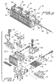
- FIGURE 1 is an exploded view of a new and improved fluid dispensing head assembly segment or modular unit which has been constructed in accordance with the principles and teachings of the present invention, and which is generally indicated by the reference character 10, it is initially noted that the primary or major components of the new and improved fluid dispensing head assembly segment or modular unit 10 which has been constructed in accordance with the principles and teachings of the present invention are substantially the same as, or virtually identical to, corresponding components of conventionally known fluid dispensing head assemblies, and consequently, such components will only be identified and briefly discussed but will not be discussed or described in detail in view of the fact that such components are well known and are not relevant to the specific characteristics or features of the present invention. Subsequently, the new features characteristic of the present invention comprising, for example, modifications to the existing or conventionally known components, will of course be disclosed and discussed in detail.
- the new and improved fluid dispensing head assembly segment or modular unit 10 is, for example, particularly adapted for use in connection with the dispensing or deposition of hot melt adhesive, however, it is to be understood that the fluid dispensing head assedmbly segment or modular unit 10 can be used, or can be adapted or modified, for the dispensing of fluids other than hot melt adhesives, such as, for example, cosmetic lotions, plastic materials, or the like. Accordingly, while such apparatus may be used to dispense or deposit any one of a plurality of different fluid materials, the following description will be oriented toward the dispensing or deposition of hot melt adhesive materials.
- the new and improved fluid dispensing head assembly segment or modular unit 10 comprises an air heater block 12 which has an air distribution block 14 operatively associated therewith, and within which a plurality of hollow air heater coils 16 are adapted to be disposed for heating incoming air for operative association with the hot melt adhesive which is to be dispensed or deposited, for example, upon a suitable substrate.
- the heater coils 16 have electrical cartridge heaters 18 respectively inserted therein, and an electrical connector 20 provides electrical power to the cartridge heaters 18.
- An air heater block cover plate 22 is adapted to be secured to the rear face of the air heater block 12 so as to close or cover such rear open face thereof.
- a temperature sensor 24 is provided for controlling the energization of the cartridge heaters 18 so as to in turn control the temperature of the incoming air.
- Incoming air is supplied to the air distribution block 14 by means of an air hose connector 26 which is fluidically connected to a suitable air regulator, not shown.
- a service block 28 is adapted to be mounted atop the air heater block 12, and the service block 28 has operatively associated therewith, and mounted upon the front face thereof, a plurality of adhesive dispensing valves 30.
- the width dimension of the service block 28 is such as to accommodate, house, or mount six (6) adhesive dispensing valves 30 upon the front face thereof.
- the fabrication of the service block 28 wherein the service block 28 has the predetermined width dimension so as to be able to accommodate, house, or mount six (6) adhesive dispensing valves 30 upon the front face thereof is noted to be exemplary only in that the service block 28 can be provided with any other desirable predetermined width dimension such that, in turn, any desirable number of dispensing valves 30 can be mounted upon the front face thereof, such as, for example, eight (8), ten (10), or the like dispensing valves 30.
- the service block 28 has further mounted upon a front region thereof an air manifold 32 which is adapted to effectively fluidically route, convey, or conduct inlet control air to the adhesive dispensing valves 30 so as to actuate the same.
- the admission of the inlet control air into the air manifold 32 is controlled by means of a suitable solenoid mechanism 34.
- a plurality of adhesive material heaters 36 are adapted to be mounted or inserted into respective bores formed within the upper region of the service block 28, and a temperature sensor mechanism 38 is provided in conjunction with the adhesive material heaters 36 so as to suitably energize the same in accordance with predetermined sensed temperature levels.
- An electrical connector 40 is also adapted to be operatively mounted upon the service block 28 so as to provide electrical power to the adhesive material heaters 36 as well as to the temperature sensor mechanism 38.
- a head or service block cover plate 42 is also mounted upon the upper surface of the service block 28 so as to close and seal the upper region of the service block 28.
- the air manifold 32 and the head or service block cover plate 42 both have predetermined width dimensions which match that of the service block 28, and that the service block 28 has a predetermined width dimension which matches that of the air heater block 12.
- all components have substantially the same width dimension whereby the overall width dimension of the particular fluid dispensing head assembly segment or modular unit 10 is predetermined in accordance with the desired number of adhesive dispensing valves 30 which are to be mounted upon or incorporated within the fluid dispensing head assembly segment or modular unit 10.
- a filter block 44 is mounted upon a rear or back surface portion of the service block 28, and the filter block 44 is provided with a basket-type filter component 46 as well as a threaded plug or nut 48 which is threadedly engaged within the filter block 44 so as to retain the filter component 46 therewithin.
- the filter component 46 serves to filter any debris or particles which may be contained within the incoming adhesive material which is conducted into the filter block 44 through means of a suitable port, not shown, provided within a rear surface portion of the filter block 44.
- a mounting plate or bracket 50 is also adapted to be fixedly secured to a side wall 52 of the service block 28.
- the mounting plate or bracket 50 also serves to thermally isolate the endmost one of the fluid dispensing head assembly segments or modular units 10 from the adhesive dispensing or deposition machine, not shown.
- each one of the fluid dispensing head assembly segments or modular units 10 is illustrated as comprising, for example, six hot melt material dispensing valves 30, in accordance with the principles and teachings of the present invention, each one of the fluid dispensing head assembly segments or modular units 10 can alternatively comprise, for example, eight, ten, or the like, hot melt material dispensing valves 30.
- FIGURE 2 discloses three fluid dispensing head assembly segments or modular units 10 which therefore comprise three sets of hot melt material dispensing valves 30 wherein each set of hot melt material dispensing valves 30 comprises six dispensing valves 30.
- the assemblage of fluid dispensing head assembly segments or modular units 10 shown in FIGURE 2 comprises eighteen dispensing valves 30.
- the assemblage of fluid dispensing head assembly segments or modular units can comprise two fluid dispensing head assembly segments or modular units 10 wherein the total number of dispensing valves 30 disposed within the assemblage of fluid dispensing head assembly segments or modular units 10 comprises twelve dispensing valves 30.
- a particular fluid dispensing head assembly segment or modular unit 10 comprises eight dispensing valves 30, then when such segment or modular unit 10 is combined or adjoined to a segment or modular unit 10 comprising six dispensing valves 30, then the total number of dispensing valves comprising the assemblage of fluid dispensing head assembly segments or modular units 10 comprises fourteen dispensing valves 30.
- the basic fluid dispensing head assembly segments or modular units 10 so as to comprise, for example, either six, eight, or ten dispensing valves 30, a plurality of fluid dispensing head assembly segments or modular units 10 can be secured together so as to in effect achieve an assemblage of fluid dispensing head assembly segments or modular units 10 wherein a particular number of dispensing valves 30 can be incorporated within the assemblage.
- each one of the service blocks 28 of each fluid dispensing head assembly segment or modular unit 10 is provided with an axially extending throughbore 54.
- a threaded rod 56 having a predetermined axial length, is adapted to be disposed or inserted through the throughbores 54 of each service block 28 of each segment or modular unit 10.
- a pair of dowel pins 58 are provided within, for example, each right side wall 52 of each service block 28 so as to be disposed within suitable apertures formed within, for example, each left side wall 52 of each service block 28.
- suitable washer and nut fastener components 60 may be threadedly secured upon the opposite ends of the threaded rod 56 whereby the plurality of segments or modular units 10 are now fixedly locked together.
- each fluid dispensing head assembly segment or modular unit is fabricated so as to accommodate, house, or mount a predetermined number of dispensing valve components, such as, for example, six, eight, or ten dispensing valves.
- a fluid dispensing head assembly which requires, for example, the incorporation therein of twelve, fourteen, sixteen, eighteen, twenty, or even a higher number of fluid dispensing valves to be incorporated therein, a plurality of the fluid dispensing head assembly segments or modular units can be secured together such that the resulting assemblage contains the desired or required number of fluid dispensing valves.
Landscapes
- Engineering & Computer Science (AREA)
- General Engineering & Computer Science (AREA)
- Mechanical Engineering (AREA)
- Coating Apparatus (AREA)
- Feeding, Discharge, Calcimining, Fusing, And Gas-Generation Devices (AREA)
- Valve Housings (AREA)
- Nozzles (AREA)
- Branch Pipes, Bends, And The Like (AREA)
- Pipeline Systems (AREA)
Abstract
Description
- The present invention relates generally to fluid dispensing head assemblies, and more particularly to a new and improved fluid dispensing head segment or modular unit assembly which enables a plurality of fluid dispensing head segment or modular unit assemblies to be secured together so as to in effect customize the fabrication of a composite fluid dispensing head assembly such that the resulting assembly is optimally sized so as to be especially adapted for particularly desired or required customer applications.
- Fluid dispensing head assemblies, such as, for example, hot melt adhesive fluid dispensing head assemblies, are known to conventionally comprise an air heater block, a service block which is mounted atop the air heater block, a plurality of fluid dispensing valves which are mounted upon a front face of the service block, a filter block mounted upon a rear face of the service block, an air manifold which is mounted atop the service block for operative cooperation with the plurality of dispensing valves, and an air distribution block which is mounted upon a rear surface of the air heater block. It is also conventional to fabricate the air heater block, the service block, the air manifold, and the air distribution block components such that the same have respective width dimensions which can mount or accommodate, for example, six (6) dispensing valves.
- While such fluid dispensing head assemblies are of course suitable or adequate for performing numerous fluid dispensing or deposition operations in accordance with specific fluid deposition applications or requirements, other fluid deposition applications may require the use of other fluid dispensing head assemblies which must accommodate or mount a number of dispensing valves which is different from the conventional fluid dispensing head assemblies housing or accommodating six fluid dispensing valves. Consequently, such other fluid dispensing head assemblies must have dimensions which are different from those of the aforenoted conventional fluid dispensing head assemblies which comprise six dispensing valves. Accordingly, such other fluid dispensing head assemblies must in effect be customized or fabricated in a custom-made manner so as to in fact comprise a greater number of dispensing valves whereby such customized or custom-made fluid dispensing head assemblies would then be suitable for accomplishing the desired dispensing or deposition operations. The customized or custom-made fabrication of such other fluid dispensing head assemblies, however, is quite time-consuming, whereby production of such other fluid dispensing head assemblies requires a considerable amount of time to achieve with the result that customer orders unfortunately require a considerable amount of time to fill.
- A need therefore exists in the art for a new and improved fluid dispensing head assembly, and more particularly for a new and improved fluid dispensing head segment or modular unit assembly which enables a plurality of fluid dispensing head segment or modular unit assemblies to be readily secured together in predetermined multiples. In this manner, fluid dispensing head assemblies of predetermined sizes can in effect be rapidly fabricated or manufactured in order to readily meet customer's requirements for such predeterminedly sized fluid dispensing head assemblies without the need for customizing or custom-making such assemblies as original single integral assemblies having the desired or required sized dimensions.
- Accordingly, it is an object of the present invention to provide a new and improved fluid dispensing head assembly.
- Another object of the present invention is to provide a new and improved fluid dispensing head assembly which comprises a fluid dispensing head assembly segment or modular unit.
- An additional object of the present invention is to provide a new and improved fluid dispensing head assembly which comprises a fluid dispensing head assembly segment or modular unit which enables a plurality of such fluid dispensing head assembly segments or modular units to be secured together.
- A further object of the present invention is to provide a new and improved fluid dispensing head assembly which comprises a fluid dispensing head assembly segment or modular unit which enables a plurality of such fluid dispensing head assembly segments or modular units to be secured together so as to readily meet customer fluid deposition or dispensing application or operation requirements.
- The foregoing and other objectives are achieved in accordance with the teachings and principles of the present invention through the provision of a new and improved fluid dispensing head assembly which comprises a fluid dispensing head assembly segment or modular unit which is adapted so as to be able to be secured together with additional segments or modular units whereby resulting fluid dispensing head assemblies or predetermined sizes are able to be achieved in order to meet or satisfy customer dispensing or deposition application requirements. More particularly, each fluid dispensing head assembly segment or modular unit is fabricated so as to accommodate, house, or mount a predetermined number of dispensing valve components, such as, for example, six (6) dispensing valves, eight (8) dispensing valves, or ten (10) dispensing valves.
- Accordingly, should a particular customer require a fluid dispensing head assembly which requires, for example, the incorporation therein of twelve (12), fourteen (14), sixteen (16), eighteen (18), twenty (20), or even a higher number of fluid dispensing valves to be incorporated therein, a plurality of the fluid dispensing head assembly segments or modular units can be secured together such that the resulting assemblage contains the desired or required number of fluid dispensing valves. For example, if a particular fluid dispensing head assemblage requires twelve (12) fluid dispensing valves in order to achieve a particular fluid dispensing or deposition operation or application, two fluid dispensing head assembly segments or modular units, each one of which comprises six (6) fluid dispensing valves, can be secured together. Similarly, if a particular fluid dispensing head assemblage requires, for example, eighteen (18) fluid dispensing valves in order to achieve another particular fluid dispensing or deposition operation or application, then three fluid dispensing head assembly segments or modular units, each one of which comprises six (6) fluid dispensing valves, can be secured together. In other words, by mixing and matching, in effect, any one of a plurality of the fluid dispensing head assembly segments or modular units, a resulting fluid dispensing head assemblage, having a predeterminedly desired or required number of fluid dispensing valves incorporated therein, can be achieved in order to readily and rapidly meet customer orders, needs, and requirements.
- Various other objects, features, and attendant advantages of the present invention will be more fully appreciated from the following detailed description when considered in connection with the accompanying drawings in which like reference characters designate like or corresponding parts throughout the several views, and wherein:
- FIGURE 1 is an exploded view of a new and improved fluid dispensing head assembly segment or modular unit which has been constructed in accordance with the principles and teachings of the present invention; and
- FIGURE 2 is a perspective view showing a new and improved fluid dispensing head assembly assemblage which has been constructed in accordance with the teachings and principles of the present invention and which comprises a plurality of the new and improved fluid dispensing head assembly segments or modular units as shown in FIGURE 1, whereby the resulting fluid dispensing head assembly assemblage incorporates therein a predetermined number of fluid dispensing valves so as to readily and rapidly meet customer application or deposition needs or requirements.
-
- Referring now to the drawings, and more particularly to FIGURE 1 thereof which is an exploded view of a new and improved fluid dispensing head assembly segment or modular unit which has been constructed in accordance with the principles and teachings of the present invention, and which is generally indicated by the
reference character 10, it is initially noted that the primary or major components of the new and improved fluid dispensing head assembly segment ormodular unit 10 which has been constructed in accordance with the principles and teachings of the present invention are substantially the same as, or virtually identical to, corresponding components of conventionally known fluid dispensing head assemblies, and consequently, such components will only be identified and briefly discussed but will not be discussed or described in detail in view of the fact that such components are well known and are not relevant to the specific characteristics or features of the present invention. Subsequently, the new features characteristic of the present invention comprising, for example, modifications to the existing or conventionally known components, will of course be disclosed and discussed in detail. - More particularly, as shown, the new and improved fluid dispensing head assembly segment or
modular unit 10 is, for example, particularly adapted for use in connection with the dispensing or deposition of hot melt adhesive, however, it is to be understood that the fluid dispensing head assedmbly segment ormodular unit 10 can be used, or can be adapted or modified, for the dispensing of fluids other than hot melt adhesives, such as, for example, cosmetic lotions, plastic materials, or the like. Accordingly, while such apparatus may be used to dispense or deposit any one of a plurality of different fluid materials, the following description will be oriented toward the dispensing or deposition of hot melt adhesive materials. As therefore seen in FIGURE 1, it is seen that the new and improved fluid dispensing head assembly segment ormodular unit 10 comprises anair heater block 12 which has anair distribution block 14 operatively associated therewith, and within which a plurality of hollowair heater coils 16 are adapted to be disposed for heating incoming air for operative association with the hot melt adhesive which is to be dispensed or deposited, for example, upon a suitable substrate. Theheater coils 16 haveelectrical cartridge heaters 18 respectively inserted therein, and anelectrical connector 20 provides electrical power to thecartridge heaters 18. An air heaterblock cover plate 22 is adapted to be secured to the rear face of theair heater block 12 so as to close or cover such rear open face thereof. Lastly, atemperature sensor 24 is provided for controlling the energization of thecartridge heaters 18 so as to in turn control the temperature of the incoming air. Incoming air is supplied to theair distribution block 14 by means of anair hose connector 26 which is fluidically connected to a suitable air regulator, not shown. - A
service block 28 is adapted to be mounted atop theair heater block 12, and theservice block 28 has operatively associated therewith, and mounted upon the front face thereof, a plurality ofadhesive dispensing valves 30. As illustrated and in accordance with the new and improved fluid dispensing head assembly segment ormodular unit 10 constructed in line with the principles and teachings of the present invention, it is seen that the width dimension of theservice block 28 is such as to accommodate, house, or mount six (6)adhesive dispensing valves 30 upon the front face thereof. The fabrication of theservice block 28 wherein theservice block 28 has the predetermined width dimension so as to be able to accommodate, house, or mount six (6)adhesive dispensing valves 30 upon the front face thereof is noted to be exemplary only in that theservice block 28 can be provided with any other desirable predetermined width dimension such that, in turn, any desirable number ofdispensing valves 30 can be mounted upon the front face thereof, such as, for example, eight (8), ten (10), or thelike dispensing valves 30. - The
service block 28 has further mounted upon a front region thereof anair manifold 32 which is adapted to effectively fluidically route, convey, or conduct inlet control air to theadhesive dispensing valves 30 so as to actuate the same. The admission of the inlet control air into theair manifold 32 is controlled by means of asuitable solenoid mechanism 34. A plurality of adhesive material heaters 36 are adapted to be mounted or inserted into respective bores formed within the upper region of theservice block 28, and atemperature sensor mechanism 38 is provided in conjunction with the adhesive material heaters 36 so as to suitably energize the same in accordance with predetermined sensed temperature levels. Anelectrical connector 40 is also adapted to be operatively mounted upon theservice block 28 so as to provide electrical power to the adhesive material heaters 36 as well as to thetemperature sensor mechanism 38. A head or serviceblock cover plate 42 is also mounted upon the upper surface of theservice block 28 so as to close and seal the upper region of theservice block 28. - It is to be noted, as may best be seen and appreciated from FIGURE 2, that the
air manifold 32 and the head or serviceblock cover plate 42 both have predetermined width dimensions which match that of theservice block 28, and that theservice block 28 has a predetermined width dimension which matches that of theair heater block 12. In this manner, when theair manifold 32 and head or serviceblock cover plate 42 are mounted upon theservice block 28, and in turn, when theservice block 28 is mounted upon theair heater block 12, all components have substantially the same width dimension whereby the overall width dimension of the particular fluid dispensing head assembly segment ormodular unit 10 is predetermined in accordance with the desired number ofadhesive dispensing valves 30 which are to be mounted upon or incorporated within the fluid dispensing head assembly segment ormodular unit 10. - It is lastly noted that a
filter block 44 is mounted upon a rear or back surface portion of theservice block 28, and thefilter block 44 is provided with a basket-type filter component 46 as well as a threaded plug ornut 48 which is threadedly engaged within thefilter block 44 so as to retain thefilter component 46 therewithin. Thefilter component 46 serves to filter any debris or particles which may be contained within the incoming adhesive material which is conducted into thefilter block 44 through means of a suitable port, not shown, provided within a rear surface portion of thefilter block 44. In order to mount the endmost one of the fluid dispensing head assembly segments ormodular units 10 upon the adhesive dispensing or deposition machine, not shown, a mounting plate orbracket 50 is also adapted to be fixedly secured to aside wall 52 of theservice block 28. The mounting plate orbracket 50 also serves to thermally isolate the endmost one of the fluid dispensing head assembly segments ormodular units 10 from the adhesive dispensing or deposition machine, not shown. - Having now described the basic components of a fluid dispensing head assembly, or more particularly, having now described the basic components of one of the fluid dispensing head assembly segments or
modular units 10 as utilized within, and in accordance with the principles and teachings of, the present invention, the unique features or characteristics of the present invention will now be described. More particularly, it is desirable in accordance with the principles and teachings of the present invention to serially dispose a plurality of the fluid dispensing head assembly segments ormodular units 10 in a side-by-side secured array so as to in effect readily and easily fabricate an extended array of fluid dispensing head assembly segments ormodular units 10 which comprises an increased number of adhesivematerial dispensing valves 30 so as to satisfy particular dispensing or deposition requirements attendant a particular dispensing or deposition operation or application. As can therefore be appreciated as a result of additional reference being made to FIGURE 2, three fluid dispensing head assembly segments ormodular units 10 are disposed in a side-by-side array and are adapted to be secured together. It is noted, as has been discussed hereinbefore, that while each one of the fluid dispensing head assembly segments ormodular units 10 is illustrated as comprising, for example, six hot meltmaterial dispensing valves 30, in accordance with the principles and teachings of the present invention, each one of the fluid dispensing head assembly segments ormodular units 10 can alternatively comprise, for example, eight, ten, or the like, hot meltmaterial dispensing valves 30. - The important or unique feature or characteristic of the present invention is that by means of serially disposing the fluid dispensing head assembly segments or
modular units 10 in the noted side-by-side array, a multiple number of basic sets of hot meltmaterial dispensing valves 30 can be provided within each resulting assemblage of fluid dispensing head assembly segments ormodular units 10. Different sets of hot meltmaterial dispensing valves 30 can also be mixed and matched in order to meet or satisfy particular dispensing or deposition requirements. For example, FIGURE 2 discloses three fluid dispensing head assembly segments ormodular units 10 which therefore comprise three sets of hot meltmaterial dispensing valves 30 wherein each set of hot meltmaterial dispensing valves 30 comprises sixdispensing valves 30. Accordingly, the assemblage of fluid dispensing head assembly segments ormodular units 10 shown in FIGURE 2 comprises eighteendispensing valves 30. Alternatively, however, the assemblage of fluid dispensing head assembly segments or modular units can comprise two fluid dispensing head assembly segments ormodular units 10 wherein the total number ofdispensing valves 30 disposed within the assemblage of fluid dispensing head assembly segments ormodular units 10 comprises twelvedispensing valves 30. Still further, if a particular fluid dispensing head assembly segment ormodular unit 10 comprises eightdispensing valves 30, then when such segment ormodular unit 10 is combined or adjoined to a segment ormodular unit 10 comprising sixdispensing valves 30, then the total number of dispensing valves comprising the assemblage of fluid dispensing head assembly segments ormodular units 10 comprises fourteendispensing valves 30. Obviously, then, by fabricating the basic fluid dispensing head assembly segments ormodular units 10 so as to comprise, for example, either six, eight, or tendispensing valves 30, a plurality of fluid dispensing head assembly segments ormodular units 10 can be secured together so as to in effect achieve an assemblage of fluid dispensing head assembly segments ormodular units 10 wherein a particular number ofdispensing valves 30 can be incorporated within the assemblage. - Accordingly, in order to achieve the side-by-side secured array or arrangement of the plurality of fluid dispensing head assembly segments or
modular units 10, each one of theservice blocks 28 of each fluid dispensing head assembly segment ormodular unit 10 is provided with an axially extendingthroughbore 54. A threadedrod 56, having a predetermined axial length, is adapted to be disposed or inserted through thethroughbores 54 of eachservice block 28 of each segment ormodular unit 10. In order to properly axially align the adjacent segments ormodular units 10 with respect to each other, a pair ofdowel pins 58 are provided within, for example, eachright side wall 52 of eachservice block 28 so as to be disposed within suitable apertures formed within, for example, eachleft side wall 52 of eachservice block 28. When the plurality of segments ormodular units 10 are aligned and disposed adjacent to each other in abutting relationship, then suitable washer andnut fastener components 60 may be threadedly secured upon the opposite ends of the threadedrod 56 whereby the plurality of segments ormodular units 10 are now fixedly locked together. - Thus, it may be seen that in accordance with the principles and teachings of the present invention, there has been provided a new and improved fluid dispensing head assembly which comprises a fluid dispensing head assembly segment or modular unit which is adapted to be secured together with additional segments or modular units whereby resulting fluid dispensing head assemblies of predetermined sizes are able to be achieved in order to meet or satisfy customer dispensing or deposition application requirements. More particularly, each fluid dispensing head assembly segment or modular unit is fabricated so as to accommodate, house, or mount a predetermined number of dispensing valve components, such as, for example, six, eight, or ten dispensing valves. Accordingly, should a particular customer require a fluid dispensing head assembly which requires, for example, the incorporation therein of twelve, fourteen, sixteen, eighteen, twenty, or even a higher number of fluid dispensing valves to be incorporated therein, a plurality of the fluid dispensing head assembly segments or modular units can be secured together such that the resulting assemblage contains the desired or required number of fluid dispensing valves.
- Obviously, many variations and modifications of the present invention are possible in light of the above teachings. It is therefore to be understood that within the scope of the appended claims, the present invention may be practiced otherwise than as specifically described herein.
Claims (24)
- A fluid dispensing head assembly modular unit for connection to at least one other similar fluid dispensing head assembly modular unit so as to form an assemblage of fluid dispensing head assembly modular units, comprising:a service block for conveying therethrough a material to be dispensed;a predetermined number of dispensing valves mounted upon said service block for receiving and dispensing the material conveyed through said service block; andmeans mounted upon said service block for enabling said service block to be fixedly connected to a similar service block of another modular unit such that a plurality of modular units can be fixedly connected together whereby an assemblage of modular units comprising a multiple number of a predetermined number of dispensing valves is created.
- The modular unit as set forth in Claim 1, wherein:
said predetermined number of dispensing valves comprises six dispensing valves. - The modular unit as set forth in Claim 1, wherein:
said predetermined number of dispensing valves is selected from a group comprising six, eight, and ten dispensing valves. - The modular unit as set forth in Claim 1, wherein said means mounted upon said service block for enabling said service block to be fixedly connected to a similar service block of another modular unit comprises:a throughbore formed within said service block; anda threaded rod disposed through said throughbore of said service block for extension through a similar throughbore formed within a service block of a similar modular unit whereby adjacent modular units can be connected together.
- The modular unit as set forth in Claim 1, further comprising:
dowel pins provided upon at least one side wall of said service block for insertion within apertures provided within a similar service block of another modular unit such that a plurality of modular units can be aligned with respect to each other in a side-by-side array. - The modular unit as set forth in Claim 1, wherein:
said dispensing valves are hot melt adhesive dispensing valves. - A hot melt adhesive material dispensing head assembly modular unit for connection to at least one other similar hot melt adhesive material dispensing head assembly modular unit so as to form an assemblage of hot melt adhesive material dispensing head assembly modular units, comprising:a service block for conveying therethrough hot melt adhesive material to be dispensed;a predetermined number of dispensing valves mounted upon said service block for receiving and dispensing the hot melt adhesive material conveyed through said service block; andmeans mounted upon said service block for enabling said service block to be fixedly connected to a similar service block of another modular unit such that a plurality of modular units can be fixedly connected together whereby an assemblage of modular units comprising a multiple number of a predetermined number of dispensing valves is created.
- The modular unit as set forth in Claim 7, wherein:
said predetermined number of dispensing valves comprises six dispensing valves. - The modular unit as set forth in Claim 7, wherein:
said predetermined number of dispensing valves is selected from a group comprising six, eight, and ten dispensing valves. - The modular unit as set forth in Claim 7, wherein said means mounted upon said service block for enabling said service block to be fixedly connected to a similar service block of another modular unit comprises:a throughbore formed within said service block; anda threaded rod disposed through said throughbore of said service block for extension through a similar throughbore formed within a service block of a similar modular unit whereby adjacent modular units can be connected together.
- The modular unit as set forth in Claim 7, further comprising:
dowel pins provided upon at least one side wall of said service block for insertion within apertures provided within a similar service block of another modular unit such that a plurality of modular units can be aligned with respect to each other in a side-by-side array. - An assemblage of first and second fluid dispensing head assembly modular units, comprising:a first service block for conveying therethrough a first material to be dispensed;a first predetermined number of dispensing valves mounted upon said first service block for receiving and dispensing the first material conveyed through said first service block;a second service block for conveying therethrough a second material to be dispensed;a second predetermined number of dispensing valves mounted upon said second service block for receiving and dispensing the second material conveyed through said second service block; andmeans mounted upon said first and sceond service blocks for enabling said first and second service blocks to be fixedly connected together such that said assemblage of modular units comprising a multiple number of a predetermined number of dispensing valves is created.
- The assemblage of modular units as set forth in Claim 12, wherein:said first predetermined number of dispensing valves comprises six dispensing valves; andsaid second predetermined number of dispensing valves comprises six dispensing valves.
- The assemblage of modular units as set forth in Claim 12, wherein:said first predetermined number of dispensing valves is selected from a group comprising six, eight, and ten dispensing valves; andsaid second predetermined number of dispensing valves is selected from a group comprising six, eight, and ten dispensing valves.
- The assemblage of modular units as set forth in Claim 12, wherein said means mounted upon said first and second service blocks for enabling said first and second service blocks to be fixedly connected together, comprises:a throughbore formed within said first and second service blocks; anda threaded rod disposed through said throughbores formed within said first and second service blocks for extension through said throughbores formed within said first and second service blocks whereby adjacent modular units can be connected together.
- The assemblage of modular units as set forth in Claim 15, further comprising:
nut members threadedly secured upon opposite ends of said threaded rod for fixedly connecting said first and second service blocks of said first and second modular units together. - The assemblage of modular units as set forth in Claim 12, further comprising:
dowel pins provided upon at least one side wall of said first service block for insertion within apertures provided within at least one side wall of said sceond service block such that said plurality of modular units can be aligned with respect to each other in a side-by-side array. - The assemblage of modular units as set forth in Claim 12, wherein:
said first and second dispensing valves are hot melt adhesive dispensing valves. - An assemblage of first and second hot melt adhesive material dispensing head assembly modular units, comprising:a first service block for conveying therethrough hot melt adhesive material to be dispensed;a first predetermined number of dispensing valves mounted upon said first service block for receiving and dispensing the hot melt adhesive material conveyed through said first service block;a second service block for conveying therethrough hot melt adhesive material to be dispensed;a second predetermined number of dispensing valves mounted upon said second service block for receiving and dispensing the hot melt adhesive material conveyed through said second service block; andmeans mounted upon said first and sceond service blocks for enabling said first and second service blocks to be fixedly connected together such that said assemblage of modular units comprising a multiple number of a predetermined number of dispensing valves is created.
- The assemblage of modular units as set forth in Claim 19, wherein:said first predetermined number of dispensing valves comprises six dispensing valves; andsaid second predetermined number of dispensing valves comprises six dispensing valves.
- The assemblage of modular units as set forth in Claim 19, wherein:said first predetermined number of dispensing valves is selected from a group comprising six, eight, and ten dispensing valves; andsaid second predetermined number of dispensing valves is selected from a group comprising six, eight, and ten dispensing valves.
- The assemblage of modular units as set forth in Claim 19, wherein said means mounted upon said first and second service blocks for enabling said first and second service blocks to be fixedly connected together, comprises:a throughbore formed within said first and second service blocks; anda threaded rod disposed through said throughbores formed within said first and second service blocks for extension through said throughbores formed within said first and second service blocks whereby adjacent modular units can be connected together.
- The assemblage of modular units as set forth in Claim 22, further comprising:
nut members threadedly secured upon opposite ends of said threaded rod for fixedly connecting said first and second service blocks of said first and second modular units together. - The assemblage of modular units as set forth in Claim 19, further comprising:
dowel pins provided upon at least one side wall of said first service block for insertion within apertures provided within at least one side wall of said sceond service block such that said plurality of modular units can be aligned with respect to each other in a side-by-side array.
Applications Claiming Priority (2)
| Application Number | Priority Date | Filing Date | Title |
|---|---|---|---|
| US576556 | 2000-05-24 | ||
| US09/576,556 US6260583B1 (en) | 2000-05-24 | 2000-05-24 | Segmented stackable head design |
Publications (3)
| Publication Number | Publication Date |
|---|---|
| EP1157746A2 true EP1157746A2 (en) | 2001-11-28 |
| EP1157746A3 EP1157746A3 (en) | 2003-05-28 |
| EP1157746B1 EP1157746B1 (en) | 2012-08-08 |
Family
ID=24304917
Family Applications (1)
| Application Number | Title | Priority Date | Filing Date |
|---|---|---|---|
| EP20010109639 Expired - Lifetime EP1157746B1 (en) | 2000-05-24 | 2001-04-19 | Segmented stackable head design |
Country Status (11)
| Country | Link |
|---|---|
| US (2) | US6260583B1 (en) |
| EP (1) | EP1157746B1 (en) |
| JP (2) | JP2001336657A (en) |
| KR (1) | KR100778464B1 (en) |
| CN (1) | CN1102714C (en) |
| AU (1) | AU746740B2 (en) |
| BR (1) | BR0101563A (en) |
| CA (1) | CA2344895C (en) |
| ES (1) | ES2391630T3 (en) |
| HK (1) | HK1043075A1 (en) |
| TW (1) | TW514597B (en) |
Cited By (3)
| Publication number | Priority date | Publication date | Assignee | Title |
|---|---|---|---|---|
| DE102004018597B3 (en) * | 2004-04-16 | 2005-12-01 | Dürr Systems GmbH | Application head for producing a liquid film |
| CN104819328A (en) * | 2015-04-24 | 2015-08-05 | 南通华东油压科技有限公司 | Cast valve body of pumping valve |
| WO2020206241A1 (en) * | 2019-04-05 | 2020-10-08 | Nordson Corporation | Applicator air manifold |
Families Citing this family (31)
| Publication number | Priority date | Publication date | Assignee | Title |
|---|---|---|---|---|
| US6220843B1 (en) | 1998-03-13 | 2001-04-24 | Nordson Corporation | Segmented die for applying hot melt adhesives or other polymer melts |
| US6906292B2 (en) * | 1998-10-29 | 2005-06-14 | Applera Corporation | Sample tray heater module |
| AUPQ528300A0 (en) * | 2000-01-27 | 2000-02-17 | Mebberson, Nicholas Barson | Fluid distribution device |
| US6499631B2 (en) * | 2001-01-26 | 2002-12-31 | Illinois Tool Works Inc. | Hot melt adhesive applicator |
| US6601741B2 (en) * | 2001-11-28 | 2003-08-05 | Illinois Tool Works Inc. | Laminated distribution manifold plate system |
| US7617951B2 (en) * | 2002-01-28 | 2009-11-17 | Nordson Corporation | Compact heated air manifolds for adhesive application |
| US6874708B2 (en) * | 2003-02-13 | 2005-04-05 | Illinois Tool Works Inc. | Automatic air-assisted manifold mounted gun |
| US7296706B2 (en) * | 2004-02-24 | 2007-11-20 | Nordson Corporation | Method and system for supporting and/or aligning components of a liquid dispensing system |
| USD536421S1 (en) | 2004-04-02 | 2007-02-06 | Nordson Corporation | Intake portion of a liquid dispensing valve |
| US7082262B2 (en) * | 2004-04-22 | 2006-07-25 | Nordson Corporation | Integral manifold for liquid material dispensing systems |
| US20050242108A1 (en) | 2004-04-30 | 2005-11-03 | Nordson Corporation | Liquid dispenser having individualized process air control |
| US20050284338A1 (en) * | 2004-06-01 | 2005-12-29 | Dwyer Patrick A | Hot melt adhesive |
| US7278550B2 (en) * | 2004-11-11 | 2007-10-09 | Nordson Corporation | Method and system for aligning components of a liquid dispensing system |
| US7631442B2 (en) | 2005-03-01 | 2009-12-15 | Louis Berkman Winter Products Company | Modular hydraulic power mechanism |
| KR100613780B1 (en) * | 2005-03-09 | 2006-08-21 | 장동원 | Multi-Nozzle Liquid Metering Valve |
| US7332692B2 (en) * | 2005-05-06 | 2008-02-19 | Illinois Tool Works Inc. | Redundant control circuit for hot melt adhesive assembly heater circuits and temperature sensors |
| US7351937B2 (en) * | 2005-05-06 | 2008-04-01 | Illinois Tool Works Inc. | Control circuits for hot melt adhesive heater circuits and applicator heads |
| ES2559003T3 (en) * | 2006-01-06 | 2016-02-10 | Nordson Corporation | Liquid dispenser with individualized process air control |
| EP2212600B1 (en) | 2008-03-28 | 2012-02-22 | FESTO AG & Co. KG | Valve array having a plurality of electrically actuatable fluidic valves |
| KR101045003B1 (en) | 2008-11-03 | 2011-06-29 | 장동원 | Multi-nozzle Valve Assembly |
| CN102261489A (en) * | 2010-05-24 | 2011-11-30 | 浙江工正科技发展有限公司 | Solvent-resistant three-way valve device with open and close functions |
| WO2013063294A1 (en) | 2011-10-27 | 2013-05-02 | Graco Minnesota Inc. | Melter cartridge |
| IN2014DN03195A (en) | 2011-10-27 | 2015-05-22 | Graco Minnesota Inc | |
| US9480996B2 (en) * | 2012-09-18 | 2016-11-01 | Ilinois Tool Works Inc. | Fluid dispensing system with nozzle heater |
| US8939330B2 (en) | 2013-03-13 | 2015-01-27 | Graco Minnesota Inc. | Removable module service seat |
| US9796492B2 (en) | 2015-03-12 | 2017-10-24 | Graco Minnesota Inc. | Manual check valve for priming a collapsible fluid liner for a sprayer |
| DE112017002691T5 (en) * | 2016-05-27 | 2019-02-14 | Universal Instruments Corporation | Placement head with a nozzle heater, system and method of use |
| KR101803748B1 (en) * | 2017-04-07 | 2017-12-01 | 김보경 | Discharging apparatus for silicone adhesive for asseembling automotive components |
| CN106976323A (en) * | 2017-04-21 | 2017-07-25 | 汤振华 | A kind of printer module installs governor motion |
| ES3035649T3 (en) * | 2017-10-31 | 2025-09-05 | Nordson Corp | Liquid material dispensing system having a sleeve heater |
| TWI855085B (en) | 2019-05-31 | 2024-09-11 | 美商葛萊兒明尼蘇達股份有限公司 | Handheld fluid sprayer |
Citations (2)
| Publication number | Priority date | Publication date | Assignee | Title |
|---|---|---|---|---|
| WO1999046057A1 (en) | 1998-03-13 | 1999-09-16 | Nordson Corporation | Segmented die for applying hot melt adhesives or other polymer melts |
| WO1999067027A1 (en) | 1998-06-22 | 1999-12-29 | Akzo Nobel N.V. | Device and method for application of a gluing system |
Family Cites Families (28)
| Publication number | Priority date | Publication date | Assignee | Title |
|---|---|---|---|---|
| US3115282A (en) * | 1959-09-22 | 1963-12-24 | Walker Mfg Co | Forced feed dispensing system |
| JPS46614Y1 (en) * | 1966-09-14 | 1971-01-11 | ||
| JPS4911453Y1 (en) * | 1967-09-11 | 1974-03-19 | ||
| US3817269A (en) * | 1969-08-22 | 1974-06-18 | Int Basic Economy Corp | Integrated manifold circuits |
| US3886898A (en) * | 1973-12-19 | 1975-06-03 | Burroughs Corp | Multiple, contiguous stripe, extrusion coating apparatus |
| US4082324A (en) * | 1976-10-04 | 1978-04-04 | Obrecht Robert E | Connection arrangement for manifold blocks |
| US4079864A (en) * | 1976-12-15 | 1978-03-21 | Cox James R | Manifold for liquid dispensing apparatus |
| US4874014A (en) * | 1987-12-21 | 1989-10-17 | Fsi International, Inc. | Flow control manifold |
| JPH02261983A (en) * | 1989-03-31 | 1990-10-24 | Ishikawajima Harima Heavy Ind Co Ltd | Cycle type distribution valve |
| JPH0741976Y2 (en) * | 1989-08-01 | 1995-09-27 | エスエムシー株式会社 | Valve mounting device |
| JP3124287B2 (en) * | 1990-11-27 | 2001-01-15 | エスエムシー株式会社 | Manifold |
| JP2554686Y2 (en) * | 1991-12-03 | 1997-11-17 | 太陽鉄工株式会社 | Manifold block |
| DE4312730A1 (en) * | 1993-04-20 | 1994-10-27 | Festo Kg | Valve station |
| JP3275665B2 (en) * | 1995-11-08 | 2002-04-15 | ダイキン工業株式会社 | Stack structure of distribution valve |
| US5672269A (en) * | 1996-02-29 | 1997-09-30 | Illinois Tool Works Inc. | Filter/pressure relief assembly for an adhesive supply unit |
| US5605720A (en) * | 1996-04-04 | 1997-02-25 | J & M Laboratories Inc. | Method of continuously formulating and applying a hot melt adhesive |
| US5730174A (en) * | 1996-07-01 | 1998-03-24 | Lubriquip, Inc. | Solenoid valve cartridge for lubrication divider valves |
| US5806720A (en) | 1996-07-19 | 1998-09-15 | Illinois Tool Works Inc. | Multi position palletizer head for adhesive supply unit |
| US5802720A (en) * | 1996-10-04 | 1998-09-08 | Pribe; Christopher A. | Shaving cloth |
| JP3616475B2 (en) * | 1997-05-23 | 2005-02-02 | 株式会社クボタ | Valve system |
| US6025729A (en) * | 1997-09-11 | 2000-02-15 | Delaware Capital Formation, Inc. | Floating spring probe wireless test fixture |
| JPH11294615A (en) * | 1998-04-10 | 1999-10-29 | Ckd Corp | Integrated valve |
| US5934562A (en) * | 1998-04-15 | 1999-08-10 | Illinois Tool Works Inc. | Hot melt adhesive dispensing system with laminated air heater |
| US6422428B1 (en) * | 1998-04-20 | 2002-07-23 | Nordson Corporation | Segmented applicator for hot melt adhesives or other thermoplastic materials |
| JPH11325291A (en) * | 1998-05-14 | 1999-11-26 | Smc Corp | Manifold for switching valve |
| JP2000070818A (en) * | 1998-09-03 | 2000-03-07 | San Tool:Kk | Heating equipment in hot melt adhesive spray application equipment |
| US6089413A (en) * | 1998-09-15 | 2000-07-18 | Nordson Corporation | Liquid dispensing and recirculating module |
| US6814310B2 (en) * | 2002-11-26 | 2004-11-09 | Nordson Corporation | Metered liquid dispensing system |
-
2000
- 2000-05-24 US US09/576,556 patent/US6260583B1/en not_active Expired - Lifetime
-
2001
- 2001-01-29 US US09/770,182 patent/US6286551B1/en not_active Expired - Lifetime
- 2001-03-14 JP JP2001072775A patent/JP2001336657A/en active Pending
- 2001-03-28 KR KR1020010016222A patent/KR100778464B1/en not_active Expired - Lifetime
- 2001-04-19 ES ES01109639T patent/ES2391630T3/en not_active Expired - Lifetime
- 2001-04-19 EP EP20010109639 patent/EP1157746B1/en not_active Expired - Lifetime
- 2001-04-23 CA CA 2344895 patent/CA2344895C/en not_active Expired - Fee Related
- 2001-04-24 BR BR0101563A patent/BR0101563A/en active IP Right Grant
- 2001-04-27 CN CN01115538A patent/CN1102714C/en not_active Expired - Lifetime
- 2001-05-17 AU AU46018/01A patent/AU746740B2/en not_active Ceased
- 2001-06-15 TW TW90110702A patent/TW514597B/en not_active IP Right Cessation
-
2002
- 2002-05-21 HK HK02103800.2A patent/HK1043075A1/en unknown
-
2012
- 2012-03-13 JP JP2012055999A patent/JP5363602B2/en not_active Expired - Lifetime
Patent Citations (2)
| Publication number | Priority date | Publication date | Assignee | Title |
|---|---|---|---|---|
| WO1999046057A1 (en) | 1998-03-13 | 1999-09-16 | Nordson Corporation | Segmented die for applying hot melt adhesives or other polymer melts |
| WO1999067027A1 (en) | 1998-06-22 | 1999-12-29 | Akzo Nobel N.V. | Device and method for application of a gluing system |
Cited By (6)
| Publication number | Priority date | Publication date | Assignee | Title |
|---|---|---|---|---|
| DE102004018597B3 (en) * | 2004-04-16 | 2005-12-01 | Dürr Systems GmbH | Application head for producing a liquid film |
| CN104819328A (en) * | 2015-04-24 | 2015-08-05 | 南通华东油压科技有限公司 | Cast valve body of pumping valve |
| WO2020206241A1 (en) * | 2019-04-05 | 2020-10-08 | Nordson Corporation | Applicator air manifold |
| CN113631278A (en) * | 2019-04-05 | 2021-11-09 | 诺信公司 | Applicator Air Manifold |
| CN113631278B (en) * | 2019-04-05 | 2023-09-05 | 诺信公司 | Applicator Air Manifold |
| US12138653B2 (en) | 2019-04-05 | 2024-11-12 | Nordson Corporation | Applicator air manifold |
Also Published As
| Publication number | Publication date |
|---|---|
| CA2344895C (en) | 2003-11-25 |
| KR20010107541A (en) | 2001-12-07 |
| ES2391630T3 (en) | 2012-11-28 |
| JP5363602B2 (en) | 2013-12-11 |
| AU4601801A (en) | 2001-12-13 |
| JP2012137186A (en) | 2012-07-19 |
| CA2344895A1 (en) | 2001-11-24 |
| US6286551B1 (en) | 2001-09-11 |
| CN1324995A (en) | 2001-12-05 |
| CN1102714C (en) | 2003-03-05 |
| EP1157746B1 (en) | 2012-08-08 |
| EP1157746A3 (en) | 2003-05-28 |
| BR0101563A (en) | 2002-01-02 |
| US6260583B1 (en) | 2001-07-17 |
| JP2001336657A (en) | 2001-12-07 |
| HK1043075A1 (en) | 2002-09-06 |
| AU746740B2 (en) | 2002-05-02 |
| KR100778464B1 (en) | 2007-11-21 |
| TW514597B (en) | 2002-12-21 |
Similar Documents
| Publication | Publication Date | Title |
|---|---|---|
| US6260583B1 (en) | Segmented stackable head design | |
| JP5722544B2 (en) | Modular system for supplying hot melt adhesives and other thermoplastic materials | |
| JP5824009B2 (en) | Modular system | |
| US10155241B2 (en) | Liquid dispenser having individualized process air control | |
| EP1316368B1 (en) | Hot melt adhesive flow control system | |
| CN1766390B (en) | Device for dispensing a heated liquid | |
| EP1166890B1 (en) | Split output adhesive nozzle assembly | |
| CN100540150C (en) | Integral manifolds and liquid distributors for distribution systems | |
| CN109641233A (en) | Applicator with current divider plate | |
| CN105935645A (en) | Variable output dispensing applicator and associated methods of dispensing | |
| US20230286012A1 (en) | Metering distribution assembly and coating system comprising the same | |
| MXPA01005143A (en) | Segmented stackable head design |
Legal Events
| Date | Code | Title | Description |
|---|---|---|---|
| PUAI | Public reference made under article 153(3) epc to a published international application that has entered the european phase |
Free format text: ORIGINAL CODE: 0009012 |
|
| AK | Designated contracting states |
Kind code of ref document: A2 Designated state(s): AT BE CH CY DE DK ES FI FR GB GR IE IT LI LU MC NL PT SE TR |
|
| AX | Request for extension of the european patent |
Free format text: AL;LT;LV;MK;RO;SI |
|
| PUAL | Search report despatched |
Free format text: ORIGINAL CODE: 0009013 |
|
| AK | Designated contracting states |
Designated state(s): AT BE CH CY DE DK ES FI FR GB GR IE IT LI LU MC NL PT SE TR |
|
| AX | Request for extension of the european patent |
Extension state: AL LT LV MK RO SI |
|
| 17P | Request for examination filed |
Effective date: 20031110 |
|
| AKX | Designation fees paid |
Designated state(s): AT BE CH CY DE DK ES FI FR GB GR IE IT LI LU MC NL PT SE TR |
|
| 17Q | First examination report despatched |
Effective date: 20061130 |
|
| REG | Reference to a national code |
Ref country code: DE Ref legal event code: R079 Ref document number: 60146937 Country of ref document: DE Free format text: PREVIOUS MAIN CLASS: B05C0005020000 Ipc: F16K0027000000 |
|
| GRAP | Despatch of communication of intention to grant a patent |
Free format text: ORIGINAL CODE: EPIDOSNIGR1 |
|
| RIC1 | Information provided on ipc code assigned before grant |
Ipc: B05C 5/02 20060101ALI20120130BHEP Ipc: F16K 27/00 20060101AFI20120130BHEP |
|
| GRAS | Grant fee paid |
Free format text: ORIGINAL CODE: EPIDOSNIGR3 |
|
| GRAA | (expected) grant |
Free format text: ORIGINAL CODE: 0009210 |
|
| AK | Designated contracting states |
Kind code of ref document: B1 Designated state(s): AT BE CH CY DE DK ES FI FR GB GR IE IT LI LU MC NL PT SE TR |
|
| REG | Reference to a national code |
Ref country code: GB Ref legal event code: FG4D |
|
| REG | Reference to a national code |
Ref country code: CH Ref legal event code: EP Ref country code: AT Ref legal event code: REF Ref document number: 569960 Country of ref document: AT Kind code of ref document: T Effective date: 20120815 |
|
| REG | Reference to a national code |
Ref country code: IE Ref legal event code: FG4D |
|
| REG | Reference to a national code |
Ref country code: DE Ref legal event code: R096 Ref document number: 60146937 Country of ref document: DE Effective date: 20121011 |
|
| REG | Reference to a national code |
Ref country code: SE Ref legal event code: TRGR |
|
| REG | Reference to a national code |
Ref country code: ES Ref legal event code: FG2A Ref document number: 2391630 Country of ref document: ES Kind code of ref document: T3 Effective date: 20121128 |
|
| REG | Reference to a national code |
Ref country code: NL Ref legal event code: VDEP Effective date: 20120808 |
|
| REG | Reference to a national code |
Ref country code: AT Ref legal event code: MK05 Ref document number: 569960 Country of ref document: AT Kind code of ref document: T Effective date: 20120808 |
|
| PG25 | Lapsed in a contracting state [announced via postgrant information from national office to epo] |
Ref country code: AT Free format text: LAPSE BECAUSE OF FAILURE TO SUBMIT A TRANSLATION OF THE DESCRIPTION OR TO PAY THE FEE WITHIN THE PRESCRIBED TIME-LIMIT Effective date: 20120808 Ref country code: CY Free format text: LAPSE BECAUSE OF FAILURE TO SUBMIT A TRANSLATION OF THE DESCRIPTION OR TO PAY THE FEE WITHIN THE PRESCRIBED TIME-LIMIT Effective date: 20120808 Ref country code: FI Free format text: LAPSE BECAUSE OF FAILURE TO SUBMIT A TRANSLATION OF THE DESCRIPTION OR TO PAY THE FEE WITHIN THE PRESCRIBED TIME-LIMIT Effective date: 20120808 |
|
| PG25 | Lapsed in a contracting state [announced via postgrant information from national office to epo] |
Ref country code: BE Free format text: LAPSE BECAUSE OF FAILURE TO SUBMIT A TRANSLATION OF THE DESCRIPTION OR TO PAY THE FEE WITHIN THE PRESCRIBED TIME-LIMIT Effective date: 20120808 Ref country code: PT Free format text: LAPSE BECAUSE OF FAILURE TO SUBMIT A TRANSLATION OF THE DESCRIPTION OR TO PAY THE FEE WITHIN THE PRESCRIBED TIME-LIMIT Effective date: 20121210 Ref country code: GR Free format text: LAPSE BECAUSE OF FAILURE TO SUBMIT A TRANSLATION OF THE DESCRIPTION OR TO PAY THE FEE WITHIN THE PRESCRIBED TIME-LIMIT Effective date: 20121109 |
|
| PG25 | Lapsed in a contracting state [announced via postgrant information from national office to epo] |
Ref country code: NL Free format text: LAPSE BECAUSE OF FAILURE TO SUBMIT A TRANSLATION OF THE DESCRIPTION OR TO PAY THE FEE WITHIN THE PRESCRIBED TIME-LIMIT Effective date: 20120808 |
|
| PG25 | Lapsed in a contracting state [announced via postgrant information from national office to epo] |
Ref country code: DK Free format text: LAPSE BECAUSE OF FAILURE TO SUBMIT A TRANSLATION OF THE DESCRIPTION OR TO PAY THE FEE WITHIN THE PRESCRIBED TIME-LIMIT Effective date: 20120808 |
|
| PLBE | No opposition filed within time limit |
Free format text: ORIGINAL CODE: 0009261 |
|
| STAA | Information on the status of an ep patent application or granted ep patent |
Free format text: STATUS: NO OPPOSITION FILED WITHIN TIME LIMIT |
|
| 26N | No opposition filed |
Effective date: 20130510 |
|
| REG | Reference to a national code |
Ref country code: DE Ref legal event code: R097 Ref document number: 60146937 Country of ref document: DE Effective date: 20130510 |
|
| PG25 | Lapsed in a contracting state [announced via postgrant information from national office to epo] |
Ref country code: MC Free format text: LAPSE BECAUSE OF FAILURE TO SUBMIT A TRANSLATION OF THE DESCRIPTION OR TO PAY THE FEE WITHIN THE PRESCRIBED TIME-LIMIT Effective date: 20120808 |
|
| REG | Reference to a national code |
Ref country code: CH Ref legal event code: PL |
|
| REG | Reference to a national code |
Ref country code: IE Ref legal event code: MM4A |
|
| PG25 | Lapsed in a contracting state [announced via postgrant information from national office to epo] |
Ref country code: CH Free format text: LAPSE BECAUSE OF NON-PAYMENT OF DUE FEES Effective date: 20130430 Ref country code: LI Free format text: LAPSE BECAUSE OF NON-PAYMENT OF DUE FEES Effective date: 20130430 |
|
| PG25 | Lapsed in a contracting state [announced via postgrant information from national office to epo] |
Ref country code: IE Free format text: LAPSE BECAUSE OF NON-PAYMENT OF DUE FEES Effective date: 20130419 |
|
| PG25 | Lapsed in a contracting state [announced via postgrant information from national office to epo] |
Ref country code: LU Free format text: LAPSE BECAUSE OF NON-PAYMENT OF DUE FEES Effective date: 20130419 |
|
| REG | Reference to a national code |
Ref country code: FR Ref legal event code: PLFP Year of fee payment: 16 |
|
| REG | Reference to a national code |
Ref country code: FR Ref legal event code: PLFP Year of fee payment: 17 |
|
| REG | Reference to a national code |
Ref country code: FR Ref legal event code: PLFP Year of fee payment: 18 |
|
| PGFP | Annual fee paid to national office [announced via postgrant information from national office to epo] |
Ref country code: ES Payment date: 20190701 Year of fee payment: 14 |
|
| PGFP | Annual fee paid to national office [announced via postgrant information from national office to epo] |
Ref country code: SE Payment date: 20190429 Year of fee payment: 19 |
|
| PGFP | Annual fee paid to national office [announced via postgrant information from national office to epo] |
Ref country code: TR Payment date: 20200331 Year of fee payment: 20 |
|
| PGFP | Annual fee paid to national office [announced via postgrant information from national office to epo] |
Ref country code: DE Payment date: 20200429 Year of fee payment: 20 Ref country code: FR Payment date: 20200427 Year of fee payment: 20 |
|
| PGFP | Annual fee paid to national office [announced via postgrant information from national office to epo] |
Ref country code: IT Payment date: 20200423 Year of fee payment: 20 Ref country code: GB Payment date: 20200427 Year of fee payment: 20 |
|
| PG25 | Lapsed in a contracting state [announced via postgrant information from national office to epo] |
Ref country code: SE Free format text: LAPSE BECAUSE OF NON-PAYMENT OF DUE FEES Effective date: 20200420 |
|
| REG | Reference to a national code |
Ref country code: DE Ref legal event code: R071 Ref document number: 60146937 Country of ref document: DE |
|
| REG | Reference to a national code |
Ref country code: GB Ref legal event code: PE20 Expiry date: 20210418 |
|
| PG25 | Lapsed in a contracting state [announced via postgrant information from national office to epo] |
Ref country code: GB Free format text: LAPSE BECAUSE OF EXPIRATION OF PROTECTION Effective date: 20210418 |
|
| REG | Reference to a national code |
Ref country code: ES Ref legal event code: FD2A Effective date: 20210903 |
|
| REG | Reference to a national code |
Ref country code: HK Ref legal event code: WD Ref document number: 1043075 Country of ref document: HK |
|
| PG25 | Lapsed in a contracting state [announced via postgrant information from national office to epo] |
Ref country code: ES Free format text: LAPSE BECAUSE OF NON-PAYMENT OF DUE FEES Effective date: 20200420 |