Technical Field
-
The present invention relates to an apparatus for
supplying a cancer therapeutic agent to a part to be treated
as an object for a cancer treatment (or therapy) in a
medical field related to a mammal and especially a human.
In the present invention, the "cancer therapeutic agent" can
be any therapeutic agent which has an effect as to a cancer
therapy and comprises, for example, an anticancer agent,
an antitumor agent and the like. The apparatus of the
present invention will be explained hereinafter with an
example in a case of a human, but it is understood that the
present invention is applicable to any mammal.
Background Art
-
There have been developed various cancer therapeutic
agents having an anticancer or antitumor effect or the like,
and they are used for a cancer therapy. Such cancer
therapeutic agent is generally administered by means of
injection in many cases. The administration of the cancer
therapeutic agent by means of the injection is a convenient
way, and in this way, the cancer therapeutic agent is
transported through blood vessels by blood to a cancerous
part (or an organ which cancerates). However, according to
this way, the blood is not only flows to the cancerous part
but also flows to other parts, so that the cancer therapeutic
agent can be transported substantially the whole of the
body.
Disclosure of Invention
-
Although the cancer therapeutic agent provides a
certain effect against the cancerous part, it often influences
normal (or healthy) parts in addition to the cancerous part,
which tends to cause a side effect. Considering that blood
containing the cancer therapeutic agent flows to various
parts including the cancerous part, there is a problem in
that the cancer therapeutic agent can not be contained in
blood at a high concentration (or content) in order to avoid
a side effect as to the other parts even when the cancer
therapeutic agent has a very remarkable effect as to the
cancerous part itself.
-
The inventors have studied in various ways for solving
the problems described above, and finally found that such
problems can be solved by supplying a cancer therapeutic
agent to substantially only an object such as a cancerous
part.
-
Thus, the present invention provides an apparatus for
supplying a cancer therapeutic agent to an object, which
apparatus comprises:
- (A) a fluid replacement supply unit which
quantitatively supplies a fluid replacement containing the
cancer therapeutic agent into a blood vessel (afferently)
leading to the object; and
- (B) a fluid replacement withdrawing unit which
quantitatively withdraws the fluid replacement from a blood
vessel (efferently) coming from the object, the fluid
replacement having passed through the object.
-
-
In the present invention, the "object" means a part of
the body (e.g. an organ such as a liver or a part thereof) to
which the cancer therapeutic agent is supplied (or applied),
and the "object" is for example a part in which cancer,
tumor (or precursor thereof) or the like develops or a part
in which those may possibly develop.
-
In addition, the "blood vessel leading to the object"
means a blood vessel located on an artery side regarding to
the object (i.e. a blood vessel through which blood flows
into the object), and such blood vessel is one to which the
fluid replacement can be supplied (or injected) with an
available medical technique. A position of such blood
vessel at which the fluid replacement is injected is
preferably as close to the object as possible on the blood
vessel as described above. It is more preferable that such
blood vessel leads into only the object. The blood vessel
generally branches off. If it is not possible to access the
blood vessel leading to only the object so as to supply the
fluid replacement to the blood vessel because of a
restriction as to a location of the object, a thickness of the
blood vessel or the like, the fluid replacement can not help
being supplied to the blood vessel upstream of a branching
off position in some cases. In such cases, although the
supplied fluid replacement flows into other portion(s) than
the cancerous part, injecting "the fluid replacement into a
blood vessel leading to the object" in the apparatus of the
present invention includes a case in which the fluid
replacement is supplied to a branching off blood vessel(s)
as far as such case provides substantially no adverse effect
upon a cancer therapy (or treatment or remedy) by using
the apparatus of the present invention, that is, as far as
other negative effect does not occur relatively to a positive
effect of treatment to the cancerous part which is provided
by using the apparatus of the present invention, and in
other words if an advantageous effect is expected as a
whole when deducting the negative effect from the positive
effect.
-
On the other hand, the "blood vessel coming from the
object" means a blood vessel located on a vein side
regarding to the object (i.e. a blood vessel through which
blood flows toward the heart from the object), and such
blood vessel is one from which the fluid replacement can be
withdrawn (or discharged) with an available medical
technique. A position of such blood vessel at which the
fluid replacement is withdrawn is preferably as close to the
object as possible on the blood vessel as described above.
It is preferable that such blood vessel comes from only the
object. Branching off blood vessels are generally join each
other at the vein side. If it is not able to access the blood
vessel coming from only the object upstream of the joining
position so as to withdraw the fluid replacement from the
blood vessel because of a restriction as to location of the
object, a thickness of the blood vessel or the like, blood
derived from the joining blood vessel(s) as described above
can not help being withdrawn together with the fluid
replacement which has passed through the object in some
cases. In such cases, although the blood flowing from
other portions than the object is also withdrawn in addition
to the fluid replacement having passed through the object,
withdrawing "the fluid replacement from a blood vessel
coming from the object, the fluid replacement having
passed through the object" in present invention includes a
case in which the blood is also withdrawn from thus
branding off blood vessel(s) as far as such case provides
substantially no adverse effect upon the cancer therapy by
using the apparatus of the present invention, that is, as far
as other negative effect does not occur relatively to a
positive effect that the cancerous part can be treated, and
in other words if an advantageous effect is expected as a
whole when deducting the negative effect from the positive
effect. Thus, withdrawing of the fluid replacement includes
a case in which the blood is withdrawn in addition to the
fluid replacement. It is also possible that blood (for
example, blood existing in the object prior to the supply of
the fluid replacement) is discharged from the portion as the
object, and the fluid replacement having passed through the
object contains the blood in this case.
-
In the present invention, "quantitatively supply" means
supplying the fluid replacement to the blood vessel in a
predetermined amount or with a predetermined flow rate,
and "quantitatively withdraw" means withdrawing the fluid
replacement from the blood vessel in a predetermined
amount or with a predetermined flow rate. It is noted that
the predetermined flow rate is not necessarily a constant
rate, and includes a case in which the flow rate is varied as
predetermined during the supplying or the withdrawing.
-
As the fluid replacement, any liquid can be used as far
as it functions, as a medium for transporting the cancer
therapeutic agent to the object and provides no adverse
effect for the cancer therapeutic agent and the object, and
the cancer therapeutic agent can be preferably
homogeneously dissolved into or dispersed in the fluid
replacement. The fluid replacement may includes other
component providing a favorable influence for the object
and/or the cancer therapeutic agent. The fluid replacement,
for example, generally contains water as a main component
and may further contain an electrolyte, a nutrient, a
stabilizer for the cancer therapeutic agent and the like. A
particularly preferred fluid replacement is stable at 20 to 50
°C. For example, a Ringer's solution, a lactated Ringer's
solution, a Ringer's solution containing a low molecular
dextrin (for example containing it at 5 %) or the like is
preferably used as the fluid replacement. It is noted that in
the case in which the cancer therapeutic agent is in a liquid
state beforehand and it can be directly supplied to the
object, the cancer therapeutic agent is not necessarily
contained in other fluid replacement. In such case, the
cancer therapeutic agent itself can be understood as "the
fluid replacement comprising the cancer therapeutic agent "
of the present invention.
-
It is noted that the fluid replacement administers (or
supplies) the cancer therapeutic agent contained therein to
the object while passing through the object (generally, all
of the contained cancer therapeutic agent is not always
absorbed by the object), and when the fluid replacement
contains other component, such component can also be
administered to the object. Furthermore, the fluid
replacement receives various components from the object
while it passes through the object. Therefore, kinds and
amounts of the other components contained in the fluid
replacement are generally different between before and
after the fluid replacement passes through the object
though the main component of the fluid replacement is the
water, and the fluid replacement often contains the blood
after passing through the object as described above.
-
A concentration of the cancer therapeutic agent in the
fluid replacement which is drawn by the apparatus of the
present invention is variously lowered depending on a
condition of the object, and thus it may be difficult to grasp
an overall dosage of the cancer therapeutic agent when the
withdrawn fluid replacement is recycled as it is in order to
be supplied to the object. Therefore, the withdrawn fluid
replacement may be disposed or wasted as it is. However,
when the side effect as to the other parts than the object by
the cancer therapeutic agent contained in the fluid
replacement can be substantially neglected (for example, in
the case of using a cancer therapeutic agent causing a
small (or unremarkable) side effect such as endostatin or
angiostatin) and the withdrawn fluid replacement contains
the blood, the blood containing the cancer therapeutic
agent may be recovered by removing water from the
withdrawn fluid replacement and returned to the body. This
recovery of the blood can be conducted by, for example,
filtration or dialysis (including diafiltration). Thereby, it is
possible to return the blood to the body and avoid an
overhydration of the body. By recovering the blood as
described above, a loss of the blood can be minimized even
if the withdrawn fluid replacement contains the blood. The
cancer therapeutic agent may be transferred to the water
side to be removed depending a kind of the cancer
therapeutic agent so that the amount of the cancer
therapeutic agent existing in the recovered blood has
substantially no adverse effect. Such case is advantageous
when the blood is contained in the fluid replacement in a
large amount since the only blood can be returned to the
body. Additionally, when the cancer therapeutic agent
exists in the blood and may cause an occurrence of a side
effect if the blood is returned to the body as it is, the
occurrence of the side effect can be prevented by adding to
the recovered blood a neutralizer which can suppress the
activity of the cancer therapeutic agent. In this case, the
recovered blood can also be returned to the body after the
addition of the neutralizer.
-
Accordingly, the apparatus of the present invention in
one embodiment preferably comprises:
(C) a blood supply unit which recovers the blood
existing in the withdrawn fluid replacement by removing the
water from the withdrawn fluid replacement and supplies
the recovered blood into other blood vessel to be returned
to the body preferably after controlling a temperature of the
recovered blood. In such embodiment, the "other blood
vessel" refer to a blood vessel which is different from the
blood vessel to be supplied with the fluid replacement, and
may be the same as the blood vessel from which the fluid
replacement is withdrawn as far as a position to which the
recovered blood is supplied locates on somewhere being
closer to the heart than the withdrawing position. It is
preferable that the "other blood vessel" is a vein.
-
There is an advantage in that the cancer therapeutic
agent can be administered to the cancerous part as the
object in a large concentration since the cancer therapeutic
agent can be supplied to substantially only the object by
using the apparatus according to the present invention.
This makes possible that the cancer therapeutic agent
which had to be administered in a small concentration due
to a concern of the side effect hitherto can be applied in a
large concentration, so that the effect of the cancer therapy
can be remarkably increased.
Brief Description of Drawings
-
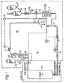
- Fig. 1 is a schematic drawing which shows the cancer
therapeutic agent supply apparatus in one embodiment of
the present invention;
- Fig. 2 is a schematic drawing which shows the cancer
therapeutic agent supply apparatus in other embodiment of
the present invention;
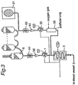
- Fig. 3 is a schematic drawing of the apparatus shown
in Fig. 1 or 2 which further comprises an artificial lung for
oxygenating autologous blood or transfusion blood (only a
part of the lung being shown);
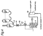
- Fig. 4 is a schematic drawing of the apparatus shown
in Fig. 1 or 2 which further comprises an artificial lung for
oxygenating fluid replacement (only a part of the lung being
shown); and
- Fig. 5 is a schematic drawing of the apparatus shown
in Fig. 1 or 2 which comprises in place of an artificial lung,
a drip chamber for bubbling oxygen gas.
-
-
Numerals in the drawings denote the following
elements:
- 1 ... fluid replacement supply pump,
- 3 ... heat exchanger,
- 4 ... supplied fluid replacement temperature sensor,
- 5 ... fluid replacement withdrawal pump,
- 6 ...heat exchanger,
- 7 ... water removal pump,
- 8 ...fluid replacement container, 9 ... drip chamber,
- 10, 11 ... catheter, 12 ... drip chamber,
- 13 ... blood recovery element,
- 14 ... removed water tank, 15 ... catheter,
- 16 ... drip chamber, 17 ... body,
- 18 ... heparin supplier,
- 19 ... supply/removal controlling mechanism,
- 21 ... heparin supplier,
- 20 ... withdrawn fluid replacement temperature sensor,
- 22 ... fluid replacement bottle, 24 ... object,
- 28 ... artificial lung, 30 ... pump,
- 31 ... transfusion blood (or autologous blood),
- 40 ... filter, 42 ... bubble detector,
- 44 ... fluid empty detector,
- 46 ... bubble detector,
- 48 ... pressure measurement element,
- 50 ... temperature sensor, 52 ... drip chamber,
- 54 ... clamp, 58 ... drip chamber,
- 62 ... fluid empty detector,
- 64 ... drip chamber, 70 ... protamine pump.
-
Detailed Description of the Invention
-
It is preferable to apply (or supply or administer) the
cancer therapeutic agent at a predetermined temperature in
view of effect (or potency) thereof in many cases. For
example, it is known that the cancer therapeutic agent such
as cisplatin, mitomycin C, bleomycin and the like exhibits
the most remarkable effect when it is applied at a
temperature of about 43 °C. Therefore, it is preferable to
make the object being in a predetermined temperature in
the case of using the apparatus of the present invention.
-
Accordingly, there is provided an apparatus for
supplying the cancer therapeutic agent to the object while
controlling the temperature of the object at a predetermined
temperature in one embodiment of the present invention.
Such apparatus can controls a temperature of the object to
which the cancer therapeutic agent is supplied by
measuring a temperature of the fluid replacement withdrawn
from the blood vessel and controlling (or adjusting) a
temperature of the fluid replacement to be supplied (or
injected) to the blood vessel based on thus measured
temperature, so that the cancer therapy can be effectively
carried out.
-
That is, when it is intended to control the temperature
of the object at a predetermined temperature depending on
the cancer therapeutic agent to be supplied to the object,
the temperature of the object is more precisely controlled
by controlling (or adjusting) the temperature of the fluid
replacement which is to be supplied, whereby the cancer
therapy can be carried out more effectively. It is noted that
such temperature controlling will be explained hereinafter
with reference to a case of mainly warming the object to a
predetermined temperature as an example. Since a case of
cooling the object is not substantially different from the
case of warming the object except cooling of the object,
those skilled in the art will readily carry out the case of
cooling the object based on the example in which the object
is warmed.
-
It is noted that depending on the kind of the cancer
therapeutic agent, the kind of the object to which the
cancer therapeutic agent is applied (thereby a treatment to
be applied to the object) and the like, a temperature at
which the object is to be kept (for example, a temperature
to which the object is to be warmed, or a temperature to
which the object is to be cooled), namely the predetermined
temperature of the object is determined when supplying the
cancer therapeutic agent to the objet while controlling the
temperature of the object using the apparatus of the
present invention. Therefore, the predetermined
temperature at which the object is to be maintained using
the cancer therapeutic agent supply apparatus as well as
an accuracy of such temperature maintenance is properly
selected by for example a doctor depending on the
treatment to be applied to the object,
-
Then, the present invention provides, in one
embodiment, an apparatus for supplying the cancer
therapeutic agent to the object while keeping (or shifting
(or changing) from an original temperature before the
supply by the apparatus and then keeping) a temperature of
an object which is a part of a body at a predetermined
temperature (T0), which apparatus comprises:
- (A) a fluid replacement supply unit which
quantitatively supplies (or meters) a fluid replacement
containing the cancer therapeutic agent into a blood vessel
leading to the object; and
- (B) a fluid replacement withdrawing unit which
quantitatively withdraws the fluid replacement having
passed through the object, from a blood vessel coming from
the object; and
- (C) optionally a blood supply unit which recovers blood
contained in the fluid replacement which has been
withdrawn, and returns the blood into other blood vessel
preferably after controlling a temperature of the recovered
blood,
the fluid replacement withdrawing unit comprising a
withdrawn fluid replacement temperature sensor which
measures a temperature of the withdrawn fluid replacement,
and the fluid replacement supply unit comprises a means
which controls (or adjusts) the temperature of the fluid
replacement to be supplied (injected) based on a different
extent between the measured withdrawn fluid replacement
temperature (T1) and the predetermined temperature of the
object (T0) (such as a difference ΔT (= T1-T0), a ratio TR
(= T1/T0) or the like). It is noted that the means which
controls the temperature of the fluid replacement to be
supplied serves to make the different extent smaller (or to
make the ratio closer to 1 in the case of the ratio). By
means of the apparatus as described above, it is possible
to carry out the more accurate control wherein the object to
which the cancer therapeutic agent is supplied is kept at a
temperature which is close to the predetermined
temperature, and preferably substantially at the
predetermined temperature. -
-
In the apparatus in the aforementioned embodiment of
the present invention, the fluid replacement which is to be
withdrawn out passes through the object to which the
cancer therapeutic agent is applied and is discharged as
soon as possible after passing through the object, and
therefore it is assumed that the temperature of the
withdrawn fluid replacement measured by the withdrawn
fluid replacement sensor (T1) represents the temperature of
the object to which the cancer therapeutic agent is supplied.
The term "represent(s)" herein is intended to mean that the
temperature of the withdrawn fluid replacement (T1) is not
necessarily the temperature of the object itself (although it
is preferably the temperature of the object itself), variation
of the fluid replacement temperature (T1) or the fluid
replacement temperature (T1) being relatively higher or
lower corresponds to variation of the object temperature or
the object temperature being higher or lower. Particularly,
when the predetermined temperature at which the object is
to be maintained or the accuracy of the temperature
maintenance at the predetermined temperature is not so
strict, for example, the above assumption is applicable.
Particularly, when a supply rate of the fluid replacement is
large depending on the treatment which is applied to the
object so that a withdrawal rate of the fluid replacement is
large, a temperature change of the withdrawn fluid
replacement during a period in which it is moved from the
object to the withdrawn fluid replacement temperature
sensor, and in particular the temperature change due to the
body temperature may be neglected since the period
required for the withdrawn fluid replacement to flow from
the object to the outside of the body after it is supplied to
the object becomes short. In such case, it is often that the
temperature of the withdrawn fluid replacement (T1) is
regarded as a true temperature of the object at that time
which is to be kept at the predetermined temperature (T0).
-
In the apparatus described above, the "means which
controls a temperature of the fluid replacement to be
supplied based on a different extent between the measured
withdrawn fluid replacement temperature (T1) and the
predetermined temperature of the object (T0)" is a means
which obtains the different extent (such as a difference or a
ratio) between the measured withdrawn fluid replacement
temperature and the predetermined temperature of the
object, and increases or decreases the temperature of the
fluid replacement to be supplied based on the different
extent. It is noted that when there is substantially no
different extent, the means keeps the temperature of the
fluid replacement as it is.
-
Concretely, when the withdrawn fluid replacement
temperature (T1) is higher than the predetermined
temperature of the object (T0) (that is, when T1-T0>0 or
T1/T0>1), the above means functions to decrease the
temperature of the fluid replacement to be supplied (or
injected). Such function can be achieved by forming a
control system which obtains the different extent between
the withdrawn fluid replacement temperature (T1) and the
predetermined temperature of the object (T0) and warms
and/or cools the fluid replacement to be supplied into the
object based on the different extent so as to make the
different extent smaller (or to make the ratio closer to 1 in
the case of the ratio). The formation of such system is well
known in the field of the temperature control. For example,
a manner can be employed in which a set temperature of a
heat exchanger (or a warming/cooing device) which controls
the temperature of the fluid replacement supplied into the
object is changed (that is, the temperature of the fluid
replacement to be supplied is lowered) depending on the
sensed different extent. Also, when the withdrawn fluid
replacement temperature (T1) is lower than the
predetermined temperature of the object (T0) (that is, when
T1-T0<0 or T1/T0<1), the above means functions to
increase the temperature of the fluid replacement to be
supplied.
-
It is noted that when there is substantially no different
extent (that is, when T1-T0=0 or T1/T0=1, and thus for
example when the temperature control of the object seems
to be working satisfactorily), the above means functions to
keep the temperature of the fluid replacement to be
supplied at that time.
-
In a case where the temperature of the fluid
replacement may change after the fluid replacement has
arrived at the object and has once reached a temperature
which is the same as or near the temperature of the object
in the object and until the fluid replacement arrives at the
withdrawn fluid replacement temperature sensor, the above
explanations are not applicable. Also, in a case where the
fluid replacement is withdrawn without its temperature
having been thermally equilibrium with the object because
of a short residence time of the fluid replacement in the
object since a supply rate of the fluid replacement is too
large (especially at the beginning of the fluid replacement
supply), the above explanations are not applicable. If there
is no change in T1 when the supply rate of the fluid
replacement is temporarily increased and/or decreased a
little, the above explanations will be applicable. In general,
it is preferable to follow the supply rate which is described
concretely in the explanations as below.
-
Alternatively, when the supply rate of the fluid
replacement into the inside of the body may be changed
depending on the treatment for the object, it is also
possible to use a means which changes the supply rate of
the fluid replacement into the inside of the body in place of
or in addition to the above means which adjusts the
temperature of the fluid replacement. That is, it is utilized
that an amount of heat transferred from the fluid
replacement to the object or from the object to the fluid
replacement changes when the supply rate of the fluid
replacement is changed. Generally, when the supply rate is
increased, an amount of heat transferred is increased.
That is, when the temperature of the fluid replacement is
lower than that of the object, the object is further cooled by
the increase of the supply rate of the fluid replacement.
Also, when the temperature of the fluid replacement is
higher than that of the object, the object is further warmed
by the increase of the supply rate of the fluid replacement,
and when the supply rate of the fluid replacement is
decreased, reversed phenomena are observed. This
embodiment to change the supply rate is particularly
preferably used for changing the temperature of the object
a little.
-
In other embodiment, the cancer therapeutic agent
supply apparatus according to the present invention
comprises a supplied fluid replacement temperature sensor
in addition to the withdrawn fluid replacement temperature
sensor, and the former sensor measures a temperature of
the fluid replacement which is supplied to object (a
supplied fluid replacement temperature, T2). In this
embodiment, an averaged value (Tav, an averaged
temperature such as an arithmetical mean, a logarithmic
mean, a weighted mean or the like) of the supplied fluid
replacement temperature (T2) and the withdrawn fluid
replacement temperature (T1) is assumed to be represent
the temperature of the object to which the cancer
therapeutic agent is applied in place of the withdrawn fluid
replacement temperature (T1) in the apparatus in the
aforementioned embodiment of the apparatus of the present
invention, and a. different extent between the averaged
temperature (Tav) and the predetermined temperature of
the object (T0) is taken into consideration in place of the
different extent between the withdrawn fluid replacement
temperature (T1) and the predetermined temperature of the
object (T0) in the aforementioned embodiment. The
temperature of the fluid replacement to be supplied is
controlled so that such former extent becomes smaller (or
as to the ratio, it becomes closer to 1 in the case of the
ratio). The other features are substantially the same as
those of the apparatus of the aforementioned embodiment.
-
Thus, in the apparatus of this embodiment, the "means
which controls a temperature of the fluid replacement to be
supplied based on a different extent between the withdrawn
fluid replacement temperature (T1) and the predetermined
temperature of the object (T0)" is a means which obtains
the different extent between the predetermined temperature
of the object and the averaged temperature of the
withdrawn fluid replacement temperature and the supplied
fluid replacement temperature, and increases or decreases,
or keeps the temperature of the fluid replacement to be
supplied based on thus obtained different extent. That is,
the different extent between the predetermined temperature
and the withdrawn fluid replacement temperature is
considered while further considering the supplied fluid
replacement temperature. Similarly to the apparatus of the
aforementioned embodiment, the supply rate change of the
fluid replacement may be applied in place of or in addition
to the control of the fluid replacement temperature.
-
Concretely, when the averaged temperature (Tav) is
higher than the predetermined temperature of the object
(T0) (that is, when Tav-T0>0 or Tav/T0>1), the above
means functions to decrease the temperature of the fluid
replacement to be supplied. When the averaged
temperature (Tav) is lower than the predetermined
temperature of the object (T0) (that is, when Tav-T0<0 or
Tav/T0<1, and for example when warming by means of the
fluid replacement seems to be insufficient), the above
means functions to increase the temperature of the fluid
replacement to be supplied. It is noted that when there is
substantially no different extent (that is, when Tav-T0=0 or
Tav/T0=1, and thus for example when the temperature
control of the object seems to be working satisfactorily),
the above means functions to keep the temperature of the
fluid replacement to be supplied at that time. Similarly to
the apparatus of the aforementioned embodiment, the
formation of a control system which obtains the averaged
temperature (Tav) of the supplied fluid replacement
temperature (T2) and the withdrawn fluid replacement
temperature (T1), obtains the different extent between the
averaged temperature (Tav) and the predetermined
temperature of the object (T0), and controls the
temperature and/or the supply rate of the fluid replacement
to be supplied based on the different extent is well known
to those skilled in the art.
-
In any embodiment of the present invention as
described above, the withdrawn fluid replacement
temperature or the averaged temperature of the withdrawn
fluid replacement temperature and the supplied fluid
replacement temperature is regarded as described above to
represent and preferably be equal to the actual temperature
of the object to which the cancer therapeutic agent is
supplied, and it is therefore preferable that the supplied
fluid replacement and/or the withdrawn fluid replacement
are not so thermally affected by others except the object.
Thus, it is preferable that the temperatures of the supplied
fluid replacement and the withdrawn fluid replacement are
measured as closely to the object as possible. Therefore,
it is preferable that the withdrawn fluid replacement is
measured at a position which is immediately downstream of
the outlet of the withdrawn fluid replacement from the blood
vessel, and the supplied fluid replacement is measured at a
position which is immediately upstream of the inlet of the
supplied fluid replacement into the blood vessel.
-
In any aspect of the present invention, the supply and
the withdrawal of the fluid replacement are carried out
through catheters as described below. It is more preferable
to use a balloon catheter (having a conduit for supplying or
discharging a fluid). The use of the balloon catheter is
advantageous in that a flow of other fluid in the blood
vessel can be stopped by inflating the balloon in the blood
vessel, and thereby it is possible to supply substantially
only the fluid replacement to the blood vessel leading to
the object, and it is also able to withdraw substantially all
fluid (which comprises the fluid replacement as a main
component) flowing through the blood vessel coming from
the object. In a particularly preferable embodiment, a
thermister is located at one end of each of the catheters
(one for the withdrawal of the fluid replacement and the
other for the supply of the fluid replacement) which end is
closer to the object (i.e. the distal end or the leading end
when the catheter is inserted) or a vicinity of such end.
The withdrawn fluid replacement temperature (T1) and/or
the supplied fluid replacement temperature (T2) are
measured while such catheters are inserted to be located
as near the object as possible, whereby the accuracy of the
object temperature assumption as described above is
further improved so that the accuracy of keeping the object
at the predetermined temperature is improved.
-
In the apparatus of the present invention, when the
blood is recovered from the withdrawn fluid replacement,
the blood supply unit preferably recovers the blood by
removing the water from the withdrawn fluid replacement so
as to preferably attain a hematocrit value (of the recovered
blood) of at least 70 % of that of a usual blood to which no
fluid replacement is supplied (usually, a normal hematocrit
value of a patient to whom the cancer therapeutic agent is
applied), and thereafter controls the temperature of the
recovered blood to a temperature around the body
temperature if necessary, and returns the blood into the
body via other blood vessel than that used for supplying or
withdrawing the fluid replacement. Therefore, an amount of
the lost blood of the patient by the supply of the cancer
therapeutic agent is minimized.
-
The cancer therapeutic agent which can be supplied by
means of the apparatus according to the present invention
is not limited as long as it can be supplied with liquid as a
medium thereof. The cancer therapeutic agent such as
liposome, retrovirus vector, adenovirus vector, interferon,
ethanol, etoposide, adriamycin, cisplatin, 5-fluorouracil,
MDR inhibitor, alkylating agent, mitomycin C, bleomycin,
angiogenesis inhibitor, VEGF antibody/receptor antagonist
can be supplied.
-
It is noted as obvious form the above description that
the cancer therapeutic agent supply apparatus can be used
for supplying other agent to a particular object in addition
to or in place of the cancer therapeutic agent. Thus, the
present invention in other aspect provides an agent supply
apparatus wherein other agent is used in addition to or in
place of the cancer therapeutic agent in the above
description. The description of the above or below can be
applied to the case of supplying said other agent than the
cancer therapeutic agent as far as a particular problem
which is caused by using such other agent does not arise.
Therefore, it will be understood that the present
specification discloses an apparatus for supplying an agent
with reference to the cancer therapeutic agent as the
example.
-
For instance, a photosensory material used for
Photodynamic diagnosis (PDD) and therapy (PDT) which
utilizes a photo chemical reaction by means of a laser
(such as an excimer dye laser and an argon dye laser) can
be supplied in place of the cancer therapeutic agent. Such
photosensory material is exemplified by hematoporphyrin
derivatives (HpD) such as dihematoporphyrin ether (DHE),
acridine orange, fluorescein, eosine yellowish, methylene
blue, rose bengal, phthalocyanine, tetracycline, proflavin,
riboflavin, erythrosine B, bonellin, peplomycin,
furocoumarin, pheophorbide, pyropheophorbide a, platinum
blue complex, adriamycin, chlorin e6, pheophorbide a and
the like.
-
When the cancer therapeutic agent is administered (or
supplied) by using the apparatus according to the present
invention, it is generally preferable to supply the fluid
replacement which has been adjusted to the predetermined
temperature (T0) beforehand upon starting to use the
apparatus. Particularly, when the averaged temperature is
used as described above, since the supplied fluid
replacement temperature (T2) is measured, it is preferable
to control the temperature of the supplied fluid replacement
such that T2 becomes the predetermined temperature (T0).
Upon such control, it is desirable to take effects of various
parameters (or factors, including a room temperature) into
the consideration as described below.
-
In a case where the cancer therapeutic agent is
administered by using the apparatus according to the
present invention, it may be not preferable to rapidly
change (for example cool or warm) the temperature of the
object to the predetermined temperature (T0) when the
predetermined temperature is greatly different from the
temperature of the object before the supply (usually the
body temperature in the normal condition). This is because
the rapid temperature change of the object gives a certain
shock, and for example electrolyte balance is broken, which
may not be preferable. Thus, in such case, a manner is
preferably employed in which a provisional predetermined
temperature (T0-1) which is near the temperature before
the supply and which is between the temperature before the
supply and the predetermined temperature is set so that the
temperature of the object reaches T0-1 first, then a next
provisional predetermined temperature (T0-2) is set by
shifting the provisional temperature toward the
predetermined temperature a little so that the temperature
of the object reaches T0-2, and then an additional next
provisional predetermined temperature is set if necessary,
....., and the temperature of the object finally
approaches the original predetermined temperature (T0) in
steps.
-
For example, in a case in which the object is to be
cooled from 37 °C to 25 °C as the predetermined
temperature (T0), the provisional predetermined
temperature (T0-1) is first set at 35 °C so that the object
temperature reaches 35 °C, then the next provisional
predetermined temperature (T0-2) is set at 33 °C when the
object temperature approaches or reaches 35 °C so that the
object temperature reaches 33 °C, ... ... ... ... ., whereby the
object temperature thus approaches 25 °C as the original
predetermined temperature (T0) little by little in steps. The
manner in which the object temperature approaches the
predetermined temperature may be stepwise as described
above or continuous. When the object temperature is
raised reversely, the above is applicable similarly. When
the object is warmed, the similar is applicable. It is of
course possible to rapidly cool or warm if no problem
occurs when the object temperature is changed to the
predetermined temperature rapidly.
-
When the cancer therapeutic agent is applied to a
selected object while the temperature of the object is
adjusted to the predetermined temperature (T0) by using
the apparatus of the present invention, in one embodiment
a temperature of the fluid replacement to be supplied is
controlled first by means of a fluid replacement temperature
controller such that the temperature of the fluid
replacement to be supplied becomes T0 (which may be the
provisional temperature as the above). The fluid
replacement thus controlled is supplied into the inside of
the body.
-
When only the temperature of the withdrawn fluid
replacement temperature (T1) is measured upon the supply
of such fluid replacement, the fluid replacement
temperature controller which has been set at the
predetermined temperature (T0) is re-set based on the
measurement of the withdrawn fluid replacement
temperature (T1), that is the temperature of the fluid
replacement to be supplied in the fluid replacement
temperature controller is re-adjusted (namely, the
temperature is set higher or lower than T0 or the
temperature is kept).
-
Also, when the supplied fluid replacement temperature
(T2) is further measured in addition to the withdrawn fluid
replacement temperature (T1), the average temperature of
these temperature is obtained, and then the averaged
temperature is compared with the predetermined
temperature (T0) to obtain the different extent followed by
re-controlling the fluid replacement temperature controller
again. It is noted that with regard to the predetermined
temperature (T0), it may be preferable to set a provisional
predetermined temperature, based on which the fluid
replacement temperature controller is adjusted followed by
gradually shift the provisional predetermined temperature
so that the original predetermined temperature is finally
reached as described above.
-
After having made the object temperature reach the
predetermined temperature, returning the object
temperature to the original object temperature (that is,
recovering the object temperature), which temperature is
usually the body temperature in a normal condition, truly
corresponds to warming or cooling the object to the
predetermined temperature. Therefore, the apparatus
according to the present invention may be used for a
temperature recovering in which a temperature of the object
is returned to the original temperature of the object which
has been shifted to the predetermined temperature through
the dosage of the cancer therapeutic agent. That is, the
control of the object temperature after dosing the cancer
therapeutic agent may be carried out by using the same
apparatus.
-
It is noted in a case in which the object temperature is
shifted to the predetermined temperature, and in particular
the object is warmed, that it may be preferable to use
oxygen containing blood as the fluid replacement when the
object needs oxygen for the purpose of its metabolism.
That is, it may be preferable that not using for example a
Ringer's solution as the fluid replacement, at least a
portion and optionally most of the fluid replacement is
replaced with blood (autologous blood or transfusion blood)
as described below. When the blood is supplied as above,
it is preferable that the blood is oxygenated by for example
an artificial lung. In this embodiment, warming is
applicable to a case in which the object is warmed from its
normal body temperature to a higher temperature as well as
a case in which the object is returned from its selectively
cooled temperature to its original normal body temperature,
and cooling is vice versa.
-
It is noted that the present invention also provides a
method for supplying the cancer therapeutic agent to the
object. The method comprises the steps of:
- (A) quantitatively supplying a fluid replacement
containing the cancer therapeutic agent, of which
temperature has been preferably adjusted, into a blood
vessel leading to the object by means of a fluid
replacement supply unit; and
- (B) quantitatively withdrawing the fluid replacement
having passed through the object from a blood vessel
coming from the object, and
- (C) optionally recovering blood contained in the fluid
replacement which has been withdrawn and returning the
blood into a body via other blood vessel preferably after
controlling a temperature of the recovered blood. In such
case, it is preferable to measure a temperature of the
withdrawn fluid replacement, and control a temperature of
the fluid replacement which is quantitatively supplied based
on a different extent between the measured withdrawn fluid
replacement temperature and the predetermined
temperature of the object. Alternatively, it is possible to
further measure the temperature of the fluid replacement to
be quantitatively supplied and control the temperature of
the fluid replacement which is quantitatively supplied based
on a different extent between the predetermined
temperature of the object and an averaged temperature of
the quantitatively supplied fluid replacement temperature
and the withdrawn fluid replacement temperature in place of
the different extent between the withdrawn fluid
replacement temperature and the predetermined
temperature of the object.
-
-
Also, temperature control of the fluid replacement to
be quantitatively supplied is preferably carried out while
considering heat transfer between the fluid replacement and
a surrounding of the apparatus until the fluid replacement
is supplied into the blood vessel. In addition, it is
preferable that the temperature of the fluid replacement to
be quantitatively supplied has been adjusted to the
predetermined temperature of the object when starting the
above method.
-
With the apparatus according to the present invention,
a leading end of a catheter is located at a certain position,
in an artery directly leading to the object to which the
cancer therapeutic agent is applied, said certain position
being the closest to the object with an available medical
technique, so as to supply the fluid replacement containing
the cancer therapeutic agent to the object via the catheter,
and a leading end of the catheter is located at a certain
position in a vein directly coming from the object, the
position being the closest to the object with the available
medical technique, so as to withdraw the fluid replacement
which has passed through the object via the catheter, and
then the withdrawn fluid replacement is disposed or wasted
as it is depending on the cancer therapeutic agent to be
used, if necessary.
-
Alternatively, when the cancer therapeutic agent has
substantially no adverse effect if it is returned to the body,
or when the treatment can be carried out while causing
substantially no adverse effect, blood which is in a
condition similar to the original blood and preferably which
is substantially equivalent to the normal blood is recovered
by removing water from the withdrawn fluid replacement,
and the recovered blood is returned into a body through a
catheter and at a position of other blood vessel such as a
vein which position is closer to the heart (so-called a heart
side position) and which vein directly or indirectly comes
from the above-mentioned vein from which the fluid
replacement is withdrawn after a temperature of the
recovered blood is adjusted (for example returned to the
body temperature), so that the cancer therapeutic agent can
be safely applied to the object without changing and
preferably without substantially increasing an amount of
body fluid which is kept in the body and without greatly
reducing an amount of the blood in the body.
-
Using the apparatus according to the present invention,
for example when the cancer therapeutic agent is supplied
to a liver as the object, a balloon catheter is inserted along
a hepatic artery to locate its leading end in a nutrient blood
vessel of tumor and the fluid replacement containing the
cancer therapeutic agent is supplied to the tumor portion,
and on the other hand, another balloon catheter is inserted
along a hepatic vein to locate its leading end in a
withdrawn blood vessel and the fluid replacement which has
passed through the object is withdrawn. When the blood is
recovered from the withdrawn fluid replacement, the
recovered blood is returned into the body through the
femoral vein. Further, for example when the cancer
therapeutic agent is supplied to a pancreas as the object, a
balloon catheter is inserted along a celiac artery to locate
its leading end in a nutrient blood vessel of tumor and the
fluid replacement containing the cancer therapeutic agent is
supplied to the tumor portion, and on the other hand,
another balloon catheter is inserted along a postcaval vein
to locate its leading end in a withdrawn vein and the fluid
replacement which has passed through the object is
withdrawn. When the blood is recovered from the
withdrawn fluid replacement, the recovered blood is
returned into the body through the femoral vein. Generally,
the fluid replacement is injected into an artery belonging to
the object to which the cancer therapeutic agent is applied
at a position of the artery which is as closer to the object
as possible with the available medical technique, and the
fluid replacement is withdrawn from a vein belonging to the
object at a position which is as closer to the object as
possible with the available medical technique. A portion at
which the recovered blood is returned is not particularly
limited.
-
In one case, the vein from which the fluid replacement
is withdrawn is preferably a vain which is intimately related
to the artery belonging to the object (thus, a vain in which
much and preferably most of the blood having passed
through such artery gathers). A portion at which the
recovered blood is returned is not particularly limited and
may be in a vein in general, and when such vein is the
same as the vain from which the fluid replacement is
withdrawn, the blood is returned at a position closer to the
heart. In order to make a temperature change of the fluid
replacement small after the temperature of the fluid
replacement reaches that of the object, the fluid
replacement is preferably withdrawn at a position which is
as closer to the object as possible as to the vain.
-
When the cancer therapeutic agent is supplied while
using the apparatus according to the present invention, it is
possible to avoid extreme overhydration of the patient by
keeping amounts of the supplied fluid replacement and the
withdrawn fluid replacement almost not different and
preferably keeping them substantially the same (thus equal).
The amounts being almost' not different does not
necessarily mean that flow rates are equal, and there is no
problem in general as far as the total amounts are equal
while avoiding an unacceptable overhydration. Therefore,
for example, a flow rate of the supply (i.e. supply rate) may
be of a finite value, and a flow rate of the withdrawal (i.e.
withdrawal rate) may be zero at an initial stage of supply of
the cancer therapeutic agent, both of the flow rates may be
substantially equal at an intermediate stage, and the flow
rate of the supply may be zero and the flow rate of the
withdrawal may be of a finite value at a final stage of the
supply of the cancer therapeutic agent. If the withdrawn
fluid replacement contains blood which is not derived from
other(s) except the object, such blood is not taken into
account in the above quantitative relationship.
-
Adjustment of the quantitative relationship as
described above may be varied depending on a condition of
the patient, a kind of the treatment in which the cancer
therapeutic agent is used and the like. When the cancer
therapeutic agent is needed to temporarily stay at the
object for a long time, the supply amount of the fluid
replacement can be made large compared with the
withdrawal amount of the fluid replacement, and only the
object may be overhydrated temporarily if it is acceptable.
-
In the apparatus according to the present invention,
when the blood is recovered by means of the fluid
replacement supply unit, the blood temperature is adjusted
before it is returned to the body inside, and such
adjustment is preferably carried out by heat exchange, and
particularly by indirect heat exchange. An apparatus
having a heater and/or a cooler for the heat exchange is
not particularly limited. In any case, it is possible that the
predetermined temperature of the recovered blood is
achieved by immersing a conduit through which the
recovered blood flows in a constant-temperature bath set at
a predetermined temperature (which is usually around the
body temperature), and such heat exchanging manner is
preferable. In one embodiment, when it has been known
beforehand that only warming or cooling is carried out, the
heat exchanger may comprise only a heater or a cooler.
-
The fluid replacement used in the present apparatus is
not particularly limited as far as it is possible to be cooled
or warmed in an appropriate manner, and it is possible to
be supplied into the body through a blood vessel so that the
cancer therapeutic agent can be supplied. Generally the
fluid replacement at least does not have adverse effect for
the cancer therapeutic agent to be administered, and
preferably the fluid replacement can help potency of such
agent. Concretely, an aqueous solution which contains a
nutrient and/or an electrolyte may be exemplified as the
fluid replacement, and an isotonic solution such as a
Ringer's solution, a lactated Ringer's solution, a Ringer's
solution containing a low molecular dextrin (for example
containing it at 5 %) or the like is particularly preferably
used as the fluid replacement, but not limited thereto.
-
In one embodiment, the apparatus according to the
present invention comprises a fluid replacement
temperature controller as the means to adjust a
temperature of the fluid replacement to be supplied. The
controller may be the indirect heat exchanger as described
above, and for example one may be used in which an
appropriate liquid (which is usually water) as a heat
transfer medium is charged in a vessel equipped with a
heater and/or a cooler and a tube which supplies the fluid
replacement is located in the liquid in for example a spiral
form. By controlling a temperature of the liquid by using
the heater and/or cooler, a temperature of the fluid
replacement at an exit of the fluid replacement temperature
controller (T3) can be controlled.
-
It is noted that when a liquid such as the fluid
replacement, blood or the like is warmed and/or cooled, the
apparatus comprising a heating means (for example, an
electric resistive heater) and/or a cooling means (for
example, a cooler using a coolant) may be used as
described above, and in a preferable embodiment, an
warming/cooling apparatus comprising a Peltier element is
used. It is noted that warming includes a case in which a
temperature is returned to an original temperature after
cooling, and that cooling includes a case in which a
temperature is returned to an original temperature after
warming, both of which may be referred to as temperature
recovering (or returning).
-
The warming/cooling apparatus comprising the Peltier
element warms or cools depending on an electric current
direction (thus, polarity) across the element, and a thermal
dose (or flux) upon warming or cooling depends on an
amperage. When the Peltier element is used, switching
between warming and cooling may be carried out freely
electrically and the amperage may be increased and
decreased easily and precisely so that response and
sensitivity of the temperature control are good and the
temperature control is accurate. The Peltier element has
been known for a long time, it has not been known or done
that its advantage is very conveniently utilized when the
features of the element are employed in the cancer
therapeutic agent supply apparatus which may be used for
the various treatments in the medical field.
-
For example, the temperature of the fluid replacement,
the blood or the like immediately after leaving the warming
and/cooling apparatus is measured, and the measured
result is fed back to a controller of the warming and/cooling
apparatus, so that increase or decrease of an amount of the
electric current through the Peltier element and switching
of its polarity may be carried out with a good sensitivity and
accuracy. The body condition of a patient to whom the
cancer therapeutic agent supply apparatus is used may
change momentarily, and when the apparatus according to
the present invention is used, such change can be detected
through T1. Thus, it is preferable that an extent of
warming/cooling of the fluid replacement to be supplied into
the body, the blood to be returned to the body or the like is
freely changed and switching between warming and cooling
is freely carried out, and in order to be thus preferable, the
warming/cooling apparatus comprising the Peltier element
is preferably used, which is particularly preferable for
controlling the temperature recovery.
-
More particularly, when an electric current is passed
across the Peltier element, one junction thereof generates
heat to be a higher temperature and the other junction
thereof absorbs heat to be a lower temperature, and when
the polarity of the voltage applied to the Peltier element is
reversed, the temperature relationship between the
junctions is reversed. Usually, one junction is warmed or
cooled by using air at a room temperature, and for example
by blowing air using a fan so that a thermal energy is
transferred between the junctions. Usually, thus warmed or
cooled junction is contacted with the fluid replacement, the
blood or the like indirectly (for example through a plastic
film, a metal thin film or the like) for the heat exchange.
Using the warming/cooling apparatus comprising the Peltier
element as described above results in compactness of the
cancer therapeutic agent supply apparatus, space saving,
improved operability and so on.
-
The fluid replacement which leaves the fluid
replacement temperature controller flows through a certain
length of a conduit until supplied into the body, during
which a temperature of the fluid replacement is affected by
a temperature of its surrounding circumstance (i.e. a room
temperature) so that the supplied fluid replacement
temperature (T2) may be different from the temperature of
the fluid replacement upon leaving the fluid replacement
temperature controller (T3). For example, when the
surrounding temperature is higher than the temperature of
the fluid replacement upon leaving the fluid replacement
temperature controller (T3), T2 is higher than T3, and when
the surrounding temperature is lower, T2 is lower than T3.
Therefore, it is usually possible that a substantive
temperature difference ΔT (=T3-T2) is present. In the
present apparatus, it is preferable to take this temperature
difference ΔT into account when the fluid replacement
temperature is adjusted based on the different extent
between the withdrawn fluid replacement temperature (T1)
and the predetermined temperature (T0) of the object. That
is, in a preferable embodiment according to the present
invention, the temperature of the fluid replacement
temperature controller (T3) is controlled considering the
temperature change of the fluid replacement between
leaving the fluid replacement temperature controller and
going into the body, namely the heat absorption from or the
heat radiation into the surrounding circumstance of the
apparatus.
-
Usually, the temperature difference is affected by
parameters such as operation conditions of the apparatus
(for example, a kind of the fluid replacement and its supply
rate, a material of the conduit for supplying the fluid
replacement and a diameter of the conduit), the
temperature of the circumstance surrounding the apparatus
(i.e. a room temperature, T4) and so on. Therefore, when
relationships between the temperature difference ΔT and
the parameters have been obtained beforehand as
calibration curves by varying the parameters variously, it
can be seen which temperature should be set in the fluid
replacement temperature controller (T3) so as to achieve an
aimed T2 under specific parameter conditions. Since
T2=T0 is generally preferable at the beginning stage of the
operation, T3 may be obtained based on the temperature
difference between the T2(=T0) and T1.
-
Particularly, in the apparatus according to the present
invention in which the withdrawn fluid replacement
temperature (T1) and the supplied fluid replacement
temperature (T2) are measured, the average of these
temperature is assumed to be the object temperature, the
different extent between the average and T0 is considered,
and T2 is selected such that the different extent becomes
smaller. Upon such selection, the temperature difference
(ΔT) is considered and the set temperature of the fluid
replacement temperature controller (T3) can be selected
(=T2+ΔT), so that the temperature (T2) can be precisely
controlled.
-
That is, since the withdrawn fluid replacement
temperature (T1) is measured and the predetermined
temperature of the object (T0) is determined beforehand
depending on the treatment, the temperature which should
be selected as T2 is obtained by T2=2T0-T1 for example if
the averaged temperature of T1 and T2 is used as the
temperature of the object. Further, ΔT can be obtained
with reference to the calibration curves which were
obtained under the specific parameter conditions as
described above, and the set temperature of the fluid
replacement temperature controller (T3) may be obtained by
T3=T2+ΔT considering the ΔT with respect to the obtained
T2, and the fluid replacement temperature controller is set
at thus obtained T3.
-
In order to obtain a temperature of a liquid which is
flowing through a length of a conduit while considering the
heat transfer to its surrounding circumstance, various
model equations are conceivable, and any model equation
may be used as far as it does not substantially adversely
affect works of the applied cancer therapeutic agent.
Concretely, the following model equation (I) for example
may be used in place of the calibration curves as described
above, so that the heat transfer between the liquid and its
surrounding circumstance is considered so as to obtain the
set temperature of the fluid replacement temperature
controller (T3):
Equation (I):
-
(wherein l(
l) is a length (m) of the conduit between the
fluid replacement temperature controller and a position at
which the supplied fluid replacement temperature is
measured, Tt is a temperature (°C) of the fluid replacement
at a time of t (s or second), v is a supply rate (linear
velocity, m/s) of the fluid replacement, a = αA/V, α is a
heat transfer coefficient (W/m
2K), A is a total surface area
(m
2) of the conduit, and V is a volume (m
3) of the fluid
replacement in the conduit). It is noted that Equation (I)
has been obtained from a general equation of the heat
transfer.
-
In one case, the fluid replacement temperature Tt may
be regarded to change linearly while the fluid replacement
flows from the fluid replacement temperature controller to
the position at which the supplied fluid replacement
temperature is measured. In such case, the fluid
replacement temperature Tt can be expressed by the
following equation:
Tt = T3 + t(T2-T3) / (I/v)
By substituting this equation in the above integral
expression equation followed by numerical calculation, the
temperature of the fluid replacement controller (T3) may be
obtained as to the aimed T2. Other equation which can
express Tt may be similarly used so as to obtain the
temperature of the fluid replacement controller (T3).
-
Alternatively, in place of the above Equation (I), the
following equation (II) may be used:
T3 = T4 - (T4-T2)eb/v
in which b= 4αl/(pdCp)
(wherein α is a heat transfer coefficient (W/m2K) of a
material of the conduit, I is a length (m) of a conduit
between the fluid replacement temperature controller and
the position at which the supplied fluid replacement
temperature is measured, p is a specific gravity (kg/m3) of
the fluid replacement, d is an outer diameter (m) of the
conduit, Cp is a specific heat capacity (J/kgK) of the fluid
replacement, and v is a supply rate (linear velocity, m/s) of
the fluid replacement)
This equation may be obtained by forming a differential
equation which expresses that an amount of heat loss of
the fluid replacement into its surrounding while the fluid
replacement flows over a very small length is equivalent to
an amount of heat gained by the surrounding, solving the
differential equation and integrating using boundary
conditions that the fluid replacement temperature is T3 and
T2 when the length of the conduit is zero and I,
respectively. It is noted that those skilled in the art can
derive this equation easily with reference to for example
"Zukai: Dennetu-kogaku no Manabikata (Illustration: How to
learn heat transfer engineering)" (1st edition, 8th printing,
by N. Kitayama, published by Ohmsha (Tokyo), July 20,
1989, pp 104-109).
-
When the supplied fluid replacement temperature (T2)
is not measured, the heat transfer between the fluid
replacement and the surrounding of the apparatus until the
fluid replacement of which temperature has been adjusted
is considered upon controlling the temperature of the fluid
replacement to be supplied. That is, when the fluid
replacement temperature which has been adjusted is
expected to become increased upon the entry into the body,
the fluid replacement is adjusted to be lower beforehand by
such temperature increase (which is thus similar to ΔT). In
the opposite case, the fluid replacement is adjusted to be
higher beforehand by ΔT.
-
In one preferable embodiment, the apparatus
according to the present invention comprises an artificial
lung which can oxygenate (add oxygen to) the fluid
replacement and/or the blood to be supplied into the body.
The artificial lung may be of any kind of device which has a
function to increase an amount of oxygen existing in the
blood or the supplied fluid replacement, so-called an
oxygen addition function or an oxygenation function, and
for example a membrane type artificial lung and a bubbling
type artificial lung may be used. In a particularly
preferable embodiment, the fluid replacement to be
supplied is introduced to the artificial lung where it is
oxygenated, and then supplied into the body. There is an
advantage in that the activity of an angiogenesis factor of
tumor cells can be suppressed and the effect provided by
the cancer therapeutic agent is further increased by making
the fluid replacement, the blood and the like to be supplied
being in a high oxygen condition,
-
In one of other preferable embodiments, when blood is
contained in the withdrawn fluid replacement, the apparatus
according to the present invention can supply autologous
blood drawn from a patient to be treated and/or transfusion
blood together with the fluid replacement into the blood
vessel depending on an amount of the blood contained in
the withdrawn fluid replacement so as to compensate for
the loss of the blood. Upon such supply, the autologous
blood and/or the transfusion blood is preferably introduced
to the artificial lung where it is oxygenated. in other
embodiment, it is possible to oxygenate by providing, in
place of or in addition to such artificial lung, a chamber
which holds a liquid such as the supplied fluid replacement,
the autologous blood or the transfusion blood and by
bubbling the liquid with oxygen (or air) while blowing it into
the liquid.
-
In the apparatus of the present invention, the recovery
of the blood by removing water from the withdrawn fluid
replacement means that a hematocrit value of the blood
recovered from the fluid replacement which is withdrawn
from the body and contains the blood (thus which value is
smaller than a hematocrit value of original blood (i.e. the
normal blood) due to dilution of the blood with the fluid
replacement) is relatively increased or substantially
recovered to the original value, and concretely it is carried
out by filtration or dialysis (including diafiltration)
(hereinafter these are generically referred to as filtration
treatment). The filtration treatment may be carried out by a
blood filtration device or a dialysis device (including a
diafiltration device) or the like which is generally used as
an artificial kidney. In the apparatus according to the
present invention, the blood after being recovered has a
hematocrit value of at least about 70 % of, preferably at
least about 90 % of, more preferably at least about 95 % of
and most preferably substantially the same as that of the
normal blood.
-
When the dialysis device (or a dialyzer) is used for the
recovery of the blood from the withdrawn fluid replacement
in the apparatus of the present invention, there is an
advantage that balance of electrolytes and/or nutrients of
the patient to whom the cancer therapeutic agent supply
method of the present invention is applied can be kept, or
the balance which has been destroyed can be recovered
since the electrolytes and/or the nutrients which are
required by the body are contained in dialysate are
transferred to the recovered blood from the dialysate and
excessive electrolytes and/or waste products which are not
required by the body are removed from the blood by the
dialysate. Thus, the blood supply unit may be preferably a
hemodialysis device (including a continuous hemodialysis
(CHD) device), or a hemodiafiltration device (including a
continuous hemodiafiltration (CHDF) device).
-
In fact, in one embodiment in which the apparatus
according to the present invention is used, a normal
hematocrit value of a normal person (about 40 to 50 %) is
diluted with the fluid replacement, and the hematocrit value
may generally lowered to about 5 to 20 %, for example
about 7 % when regarding whole of the withdrawn fluid
replacement to be as blood, and such diluted hematocrit
value is recovered up to about 30 to 50 % after being
recovered. Therefore, a hematocrit value recovery ratio (a
hematocrit value after recovery to a normal hematocrit
value) is about 0.7 to 1.00.
-
In one embodiment of the present invention, there is
provided an apparatus for supplying the cancer therapeutic
agent to the object while warming the object, which
apparatus can be preferably used for example when the
object is warmed to a high temperature at which cancer
cells may be killed though normal cells are not affected.
Concretely, it has been turned out that the cancer cells are
killed at about 42 °C, and the apparatus can be applied in
the case of supplying the cancer therapeutic agent while
warming the only object in which such cancer cells are
contained.
-
The present invention will be further explained
hereinafter in detail with reference to the accompanying
drawings.
-
Fig. 1 is a diagram (flow sheet) which schematically
shows the cancer therapeutic agent supply apparatus of the
present invention, which comprises (A) the fluid
replacement supply unit comprising a fluid replacement
container (8) which contains the cancer therapeutic agent,
a fluid replacement supply pump (1) (with functions of
metering a pumping rate and its adjustment) which supplies
the fluid replacement into an organ (24) as the object from
the fluid replacement container (8), a fluid replacement
temperature controller (3) and a drip chamber for fluid
replacement (9), and the temperature of the fluid
replacement (T2) which is supplied into the object (24)
through a balloon catheter (10) is measured by a supplied
fluid replacement temperature sensor (4).
-
Also, the shown apparatus comprises (B) a fluid
replacement withdrawing unit, which comprises a fluid
replacement withdrawal pump (5) which withdraws the fluid
replacement from the object (17) as a part in the body (17),
and the fluid replacement withdrawal pump supplies the
fluid replacement into the tank (14). The fluid replacement
may be disposed of in an appropriate manner or wasted as
it is. The temperature of the withdrawn fluid replacement
(T1) is measured by a withdrawn fluid replacement
temperature sensor (20). It is noted that a fluid
replacement bottle (22) is provided in the blood withdrawing
unit so as to fill conduits and elements in the apparatus
with the fluid replacement upon starting the apparatus
operation. Appropriate conduits (such as a silicone tube, a
polyvinyl chloride tube or the like, shown with thicker lines
in the drawing) connect between those units or various
elements which constitute the units, and catheters (10 and
11) are used for supplying the fluid replacement to the
object and withdrawing the fluid replacement from the
object.
-
In the fluid replacement supply unit (A), the fluid
replacement supply pump (1) is one which can
quantitatively inject into the body (17) the fluid replacement,
for example, usually at 10 to 800 ml/min., preferably 50 to
500 ml/min. and more preferably 100 to 400 ml/min. A
practical supply rate of the pump is appropriately selected
within those ranges depending on a purpose of the
treatment for the object. As the pump which can
quantitatively deliver (thus meter) the fluid replacement as
described, a roller pump may be exemplified which is often
used for the delivery of blood. It is noted that in order to
carry out the speedy temperature adjustment of the object,
the supply rate is preferably relatively large, and for
example a supply rate in the range 100 to 400 ml/min. is
further preferably used (particularly in the case of a brain
of an adult as the object). In place of the roller pump, a
centrifugal pump may be used, wherein an appropriate flow
rate control means such as a valve, an inverter function or
the like is preferably combined.
-
The withdrawal of the fluid replacement is carried out
by means of the fluid replacement withdrawal pump (5).
This pump and a flow rate thereof may be substantially the
same as those of the fluid replacement supply pump (1).
However, if the withdrawn fluid replacement contains blood,
it is preferable to use a pump which can additionally
withdraw the fluid by an excessive amount of the blood.
The flow rates of the fluid replacement supply pump (1) and
the fluid replacement withdrawal pump (5) may be different
or the same, and these pumps are operated by a controller
(19) such that a total amount of the supplied fluid
replacement and that of the withdrawn fluid replacement (or
an amount excluding the blood when the withdrawn fluid
replacement contains the blood) are almost or substantially
the same so as to avoid the excessive overhydration of the
body. The withdrawal of the fluid replacement is not
necessarily carried out from the starting of the supply of
the fluid replacement, and the withdrawal of the fluid
replacement is usually carried out after a predetermined
period from the beginning of the supply of the fluid
replacement has passed. Further, the withdrawal of the
fluid replacement is not necessarily stopped immediately at
the end of the supply of the fluid replacement, and the
withdrawal of the fluid replacement is usually stopped after
a predetermined period from the end of the supply of the
fluid replacement has passed.
-
When the supply rate of the fluid replacement is
controlled by for example a motor rotational speed of the
fluid replacement pump (1), a flow meter is not necessarily
provided as an additional element, but it may be located in
a conduit for the fluid replacement so as to confirm the
supply rate of the fluid replacement. The flow meter may
be for example an electromagnetic flow meter. Further, the
pump preferably has a control function which makes the
supply rate as predetermined when it is not so (for example,
a function to change the rotational speed of the pump motor
(such as an inverter function) or a function to change a
pressure loss of a conduit (such as a valve)). When the
quantitative supply of the fluid replacement pump (1) is
ensured, the flow meter may be omitted, and in this sense,
the apparatus shown in the drawing has no flow meter.
Generally, a flow meter may be provided in any conduit
through which a fluid has to be supplied at a predetermined
flow rate, and combination of the flow meter with a pump
ensures a predetermined flow rate (thus quantitative
withdrawal or supply). As to the other pumps (5 and 7), the
same as to the pump (1) is applicable except the flow rate
ranges as described above.
-
The container (8) may be a plastic vessel or bag in
which the fluid replacement containing the cancer
therapeutic agent is enclosed, or may be a bottle in which
the fluid replacement taken out from such container is
stored. There are provided the drip chamber (56) and a
fluid empty detector (44) between the container (8) and the
pump (1). The fluid replacement supply unit may further
include in addition to the above described elements, other
drip chamber (9, having a pressure gauge P) for the
removal of bubbles, which removes the bubbles entrained
with the fluid replacement if any. Similar drip chambers (12
and 16) are provided also in (C) a blood supply unit in a
embodiment which is described below with referring to Fig.
2. It is noted that a filter (40) may be provided so as to
remove contaminants in the fluid replacement and a bubble
detector (42) may be provided for check the presence of the
bubbles in the fluid replacement.
-
A diagram (flow sheet) of other embodiment of the
cancer therapeutic agent supply apparatus according to the
present invention is schematically shown in Fig. 2. In the
shown embodiment, the apparatus further comprises (C) the
blood supply unit in addition to the embodiment shown in
Fig. 1, which unit recovers blood by removing water from
the withdrawn fluid replacement, and returns the recovered
blood into the body (17). The blood supply unit (C)
transports the fluid replacement withdrawn from the object
(24) to a blood recovery element (13) such as a
hemofiltration device (or a diafiltration device) through the
blood drip chamber (12) by an action of the -fluid
replacement withdrawal pump (5), and removes water
contained in the fluid replacement into a removed water
tank (14) at the blood recovery element (13) to recover the
blood. The blood recovery element (13) optionally
comprises a water removal pump (7), and the removed
water is stored in the tank (14).
-
The blood recovered by the removal of the water is
transferred through the heat exchanger (6) controlling the
temperature of the blood and a blood return drip chamber
(16) and returned to the body through other blood vessel.
The heat exchanger (6) is provided with a temperature
sensor (50) in order to control the temperature of the
recovered blood. For passing the recovered blood through
the heat exchanger (6) and returning it into the body, a
discharge pressure of the fluid replacement withdrawal
pump (5) can be used.
-
In Fig. 2 as similarly to Fig. 1, appropriate conduits
(such as a silicone tube, a polyvinyl chloride tube or the
like, shown with thicker lines in the drawing) connect
between those units or various elements which constitute
the units, and catheters (10 and 11 and 15) are used for
supplying the fluid replacement to the object, withdrawing
the fluid replacement from the object and returning the
recovered blood into the body.
-
The apparatus of the present invention shown in Fig. 2
comprises the fluid replacement withdrawal pump (5) for
quantitatively withdrawing the fluid replacement which has
passed through the object as well as the element (13) for
recovering the blood by removing water from the fluid
replacement which has withdrawn and transferred to it. The
pump (5) preferably quantitatively withdraws the fluid
replacement through the catheter (11) at a rate in the range
usually 10 to 600 ml/min., preferably 50 to 400 ml/min., and
more preferably 80 to 300ml/min. from the body. The
practical flow rate of the pump (5) may be selected as
required within such ranges depending on a purpose of the
treatment. As the pump (5), one which is of the same type
of that of the fluid replacement pump (1) may be used, and
it may be cooperated with a flow meter (not shown) as
described above.
-
Upon using the apparatus of the present invention
shown in Fig. 2, the fluid replacement is withdrawn by
means of the catheter (11) through a vein from the object,
and it is introduced through the fluid replacement
withdrawal pump (5) to an inlet for the fluid replacement of
the blood recovery element (or a means for recovering the
blood) (13) which is preferably a disposable product. In the
apparatus of the present invention, the recovery element
(13) is preferably a dialysis device (in which a dialysate
(102) is supplied to the recovery element (13) as shown) or
a filtration device, and the control of the element is
preferably carried out based on the hematocrit values as
measures before the blood is in a normal situation and after
the blood is recovered. Measurement of the hematocrit
value may be conducted by obtaining a volume percentage
(%) of red blood cells after the recovered blood is
subjected a centrifugation treatment.
-
It is convenient to measure a flow rate of the supplied
fluid replacement and a flow rate of liquid discharged out
from the recovery element (13) (which is also referred to as
"filtrate") as well as a total amount of the fluid replacement
which has been supplied and a total amount of the filtrate
which has been discharged, and to control a patient not to
be in an excessive overhydration condition or not to be in
an excessive dehydration condition, and usually such
control is sufficient. It is noted that when the dialysis
device is used as the recovery element (13), an amount of
the dialysate which has been supplied to the dialysis device
is included in an amount of the filtrate, and thus such
amount of the dialysate has to be deducted from the amount
of the filtrate.
-
The recovery element (13) may include a pump (7) on
its filtrate side when necessary, so that a pressure
difference across the recovery element (13) can be further
increased (and thus a controllable range of the filtration
pressure (or a pressure difference upon the filtration
operation) is enlarged), whereby a filtrate rate becomes
more versatile due to using the pump (7). The recovery
element (13) of course dehydrates by means of only the
pressure difference produced by the pump (5) between the
withdrawn fluid replacement side (a delivery pressure) and
the permeate side (atmospheric pressure) produced by the
pump (5), which is so-called natural filtration or natural
dehydration (or water removal). In the case of the natural
dehydration, the filtrate is collected in the filtrate container
(14) without passing through the pump (7).
-
When the pump (1) is running, the filtrate rate from
the recovery element (13) (Vb ml/min., provided that the
supply rate of the dialysate is deducted from Vb in the case
of the dialysis operation) is preferably substantially smaller
than a supply rate of the fluid replacement supplied into the
body (Vd ml/min.) so that a hematocrit value of the blood in
the body is kept not higher than before the beginning of the
supply of the cancer therapeutic agent. This is based on
an idea that in order to make the temperature adjusting
effect by means of the apparatus of the present invention
effective, it is preferable to temporarily keep a certain
amount of the fluid replacement within the region of the
object. Therefore, in a preferable embodiment of the
apparatus according to the present invention, the flow rates
are controlled to satisfy the relationship of 0.1 Vd ≤ Vb ≤ Vd
(wherein Vd ≠ 0). When Vb is smaller than 0.1Vd (i.e. Vb <
0.1Vd), an amount of the body fluid is considerably
excessive temporarily, which is not preferable. On the
other hand, when Vb is substantially larger than Vd, body
fluid is excessively reduced from the object, which is not
preferable. However, Vb being larger than Vd is not
completely excluded in the apparatus of the present
invention, and Vb may be larger than Vd if no adverse
effect occurs in the treatment where the apparatus of the
present invention is used.
-
In the apparatus of the present invention, the fluid
replacement may comprise an aqueous solution comprising
a low molecular material (such as an electrolyte, a
saccharide (for example glucose)) as a main component in
many cases. A total amount of the filtrate (provided that an
amount of the dialysate is deducted from Vb in the case of
the dialysis device as the recovery element) during the
operation of the apparatus of the present invention is most
preferably substantially the same as a total amount of the
fluid replacement which has been supplied during the
operation, which means under the consideration of the
preferable relationship of 0.1Vd ≤ Vb ≤ Vd as described
above that operation periods of the pump (1) and the pump
(5) and optionally the pump (7) may be different, and that
even though the pump (1) is being stopped, the pump (5)
may be being operated so that Vb is a some substantive
rate. The total amount of the filtrate (provided that an
amount of the dialysate is deducted from Vb in the case of
the dialysis device as the recovery element) is not
necessarily substantially the same as the total amount of
the supplied fluid replacement, and these amounts may be
different as far as no problem occurs during the treatment.
From such viewpoint, it is generally sufficient to keep a
relationship of for example 0.8 x total amount of filtrate
(provided that an amount of the dialysate is deducted from
Vb in the case of the dialysis device as the recovery
element) ≤ total amount of supplied fluid replacement
(provided that an amount of the dialysate is deducted from
Vb in the case of the dialysis device as the recovery
element) ≤ 1.2 x total amount of filtrate (provided that an
amount of the dialysate is deducted from Vb in the case of
the dialysis device as the recovery element). Since a
certain period is required for the fluid replacement to be
discharged after passing the object, the pumps (5) and (7)
of course do not have to be started simultaneously with the
operation start of the pump (1). It is noted that during a
practical treatment or remedy, the supplied fluid
replacement may be discharged as urine, which is included
by the total amount of the filtrate in the present
specification. That is, the urine is regarded to be the
filtrate and the above relationship is considered (provided
that a rate of the urine is not included in the filtrate rate
Vb).
-
In the shown embodiment of the apparatus, the fluid
replacement withdrawal pump (5) has a function to withdraw
the fluid replacement from the object (24), a function to
supply the fluid replacement to the recovery element (13)
so as to allow the removal of the water and a function to
return the recovered blood to the body (17) thereafter. It is
obvious for those skilled in the art that these functions may
also be achieved by separate pumps while providing buffers
(or reservoirs) in-between.
-
The blood supply unit of the apparatus of the present
invention may include the drip chamber (12) for the removal
of bubbles and the anticoagulant supply element (18), for
example a heparin supply device to prevent coagulation of
the recovered blood by supplying heparin. It is noted that
the anticoagulant (for example, heparin, futhan (i.e.
nafamostat mesilate) or the like) or the like) may supplied
at any other suitable position in the apparatus of the
present invention. In the shown embodiment, the heparin
supply device (18) is located in the blood supply unit, and
the supplied heparin does not substantially transfer to the
filtrate even though it passes through the blood recovery
element (13) (namely, remaining in the recovered blood).
-
It is noted that in a particularly preferred embodiment
the fluid replacement to be quantitatively supplied to the
object contains heparin beforehand. For example, as
shown in Fig. 2, the fluid replacement is supplied with
heparin by means of the a heparin supply device (21) after
it flows out from the heat exchanger (3), and thereafter, the
fluid replacement containing the heparin is supplied to the
object (24). The heparin has a high affinity with an
angiogenesis factor of the cancer cell, so that the
angiogenesis factor is trapped by the heparin supplied from
the fluid replacement and finally withdrawn out of the body
together with the fluid replacement. The heparin trapping
the angiogenesis factor is wasted as it is in the case of Fig.
1, or discharged together with the water on a filtrate side
by means of the blood supply unit. in the case of Fig. 2.
Therefore, the effect of the therapeutic agent can be
increased further more by making the object contain the
heparin beforehand.
-
The apparatus of the present invention comprises the
blood supply unit which adjusts the temperature of the
recovered blood which may be at a higher or lower
temperature to around the normal body temperature, and
supplies such blood into a blood vessel (vein). Concretely,
the unit comprises a heat exchanger for warming/cooling (6)
which may be able to adjust the recovered blood to around
37 °C and supply it to usually a vein at a position which is
closer to the heart. In the concrete, upon using the
apparatus according to the present invention, the recovered
blood passes the heat exchanger (6) by way of a conduit
which is connected to an blood outlet of the blood recovery
element (13), and injected into the vein through the
catheter (15). In this case, there may be provided a
protamine supply pump (70) (for neutralization of the
heparin), a drip chamber for bubble removal (16) and a
bubble detector (46).
-
In a preferable embodiment of the present invention, a
supply/removal (dehydration) control mechanism (19) is
provided which automatically controls each of the flow rate
of the supplied fluid replacement Vd, the flow rate of the
withdrawn fluid replacement, and the flow rate of the filtrate
Vb so as to keep a body fluid amount as desired based on
the balance of the flow rates. When the urine is discharged,
the control of the balance may be carried out while
considering an amount of the urine. When the
supply/removal control mechanism (19) is used in the
apparatus of the present invention, the flow rate of the
supplied fluid replacement into the blood vessel, the flow
rate of the withdrawn blood from the blood vessel, and the
flow rate of the filtrate (thus, delivery rates of the pumps
(1), (5) and (7), provided that the delivery rate of the pump
(7) includes a rate of the dialysate in the case of the
dialysis device as the recovery element) should have to be
in controlled conditions along with a purpose of the
treatment in which the apparatus is used. That is, the
pumps (1) and (5) and optionally the pump (7) should be
cooperated as shown with the broken lines such that Vb and
Vd satisfy the ranges for them as described above, and the
relationship between Vb and Vd as described above and the
relationship between the total amount of the filtrate
(provided that an amount of the dialysate is deducted in the
case of the dialysis device as the recovery element) and
the total amount of the supplied fluid replacement as
described above are satisfied. Such control is well known
to those skilled in the art and employed in an operation of
an artificial kidney. It is noted that in place of the pump
(7), other pump may be located on the recovered blood side
of the blood recovery element (13) (i.e. downstream of the
recovery element).
-
For example, it is not necessarily required that the
filtrate of which amount corresponds to an amount of the
supplied fluid replacement is immediately discharged. Of
course, it may be possible that the filtrate is immediately
discharged, but it is preferable that the fluid replacement is
held in the body for a certain period, and then withdrawn
gradually from the body so as to avoid the excessive
overhydration of the body fluid in order to attain the supply
of the cancer therapeutic agent. Vb and Vd are preferably
controlled by the supply/removal control mechanism (19) so
as to achieve such purpose.
-
Alternatively, hematocrit values of the withdrawn fluid
replacement and/or the recovered blood are measured on
line using a non-contact type hematocrit measuring device,
and the supply/removal control mechanism (19) controls the
flow rates of the pumps (1), (5) and (7) based on the
measurements of the hematocrit values so as to keep the
hematocrit value of the withdrawn fluid replacement for
example not smaller than 5 % and/or to keep the hematocrit
value of the recovered blood for example at least 40 %.
-
The cancer therapeutic agent supply apparatus of the
present invention shown in Fig. 2 are possible to be used
for controlling the temperature of the object for example as
described below. It is noted that such control of the
temperature is also similarly applicable to the apparatus
shown in Fig. 1.
Case 1
-
Fluid replacement is charged beforehand from a fluid
replacement bottle (22) into the elements and the conduits
in the apparatus. First, a predetermined temperature (T0)
to which the object is controlled and operation conditions
such as a supplied fluid replacement rate, a withdrawn fluid
replacement rate and so on are determined depending on
an object (24) to which the cancer therapeutic agent is
applied and the treatment for the object. Then, a heat
exchanger (3) is operated, and its adjusting temperature
(T3) is set at for example the predetermined temperature
(T0). Upon this, the adjusting temperature (T3) may be
shifted a little from the predetermined temperature (T0)
considering the heat absorption or heat loss after leaving
the heat exchanger (3) until entering the body (namely, ΔT)
as well as the temperature change after entering the body
until reaching the object.
-
Each catheter is inserted into the blood vessel, and
the pump (1) is operated and the fluid replacement is
supplied from the fluid replacement tank (8) to the heat
exchanger (3), whereby the fluid replacement temperature
is adjusted to or near the predetermined temperature (T0)
and then the fluid replacement is supplied into the blood
vessel. Simultaneously or a predetermined period later, the
pump (5) withdraws the fluid replacement from the blood
vessel, and the temperature thereof (T1) is measured by
the temperature sensor (20). The withdrawn fluid
replacement is supplied to the blood recovery element (13)
where the blood is separated by means of filtration. Upon
filtration, the dehydration (or water removal) pump (7) may
be optionally operated so as to help the blood removal.
The blood recovered by means of the filtration is passed
through the heat exchanger (6) so as to heat to a
temperature around the body temperature and then returned
into the body through the catheter (15).
-
The above operation is carried out in the case where
the measured withdrawn fluid replacement temperature (T1)
may be regarded to represent an actual temperature of the
region of the object, and thus the different extent between
T1 and the predetermined temperature of the object region
(T0), and for example the difference ΔTa (=T1-T0) is
obtained. When ΔTa > 0, it means that the object has not
been sufficiently cooled, and thus an operation to lower the
set temperature (T3) of the heat exchanger (3) is carried
out, which may be manually or automatically.
-
On the other hand, when ΔTa < 0, it means that the
temperature of the object has been excessively cooled, and
an operation to raise the set temperature (T3) of the heat
exchanger (3) is carried out. Thereafter, the withdrawn
fluid replacement temperature is measured again, and ΔTa
is obtained similarly. Based on the obtained ΔTa, the set
temperature (T3) of the heat exchanger (3) is changed.
The time interval between the first calculation of ΔTa and
the second calculation of ΔTa is not particularly limited, but
when it is excessively long, the withdrawn fluid replacement
temperature (T1) is likely to hunt, so that the interval is
preferably short. It is of course possible that the withdrawn
fluid replacement temperature (T1) is continuously
measured, so that the set temperature (T3) of the heat
exchanger (3) is considered while considering a
characteristic of the temperature difference ΔTa (such as
an absolute value of the temperature difference, a change
rate with time of the temperature difference or the like).
The measurement and the change of the set temperature
(T3) of the heat exchanger (3) as described above are
repeated such that ΔTa becomes smaller whereby the
withdrawn fluid replacement temperature (T1) approaches
the predetermined temperature of the object (T0) and such
temperature is kept. It is noted that when ΔTa is
substantially zero, the set temperature (T3) of the heat
exchanger (3) does not particularly have to be changed.
Case 2
-
Although in Case 1, only the withdrawn fluid
replacement temperature (T1) is taken into account, the
supplied fluid replacement temperature (T2) is also
considered in addition to the withdrawn fluid replacement
temperature (T1) in Case 2. In this case, the averaged
temperature Tav of T1 and T2 (=(T1+T2)/2) may be
regarded to indicate the actual temperature of the object
(T0), and this case is generally superior in the estimation
of the object temperature to Case 1 wherein only T1 is
considered. Similarly to Case 1 described above, the
different extent between the averaged temperature (Tav)
and the predetermined temperature of the object region
(T0), for example the difference ΔTb (=(T1-T2)/2-T0) is
obtained. The others are substantially the same as those
in Case 1. It is noted that T1 and T2 have the same weight
in this case so as to obtain the averaged value, but it may
be possible optionally to change their weights. For
example, it is possible to use 1.5xT1 in place of T1, and
0.5xT2 in place of T2. Particularly since T1 is affected by
the object temperature, it may be preferable that T2 is
regarded to be heavier.
-
When ΔTb > 0, it means that the object has not been
sufficiently cooled, and thus an operation to lower the set
temperature (T3) of the heat exchanger (3) is carried out.
On the other hand, when ΔTb < 0, it means that the object
has been excessively cooled, and an operation to raise the
set temperature (T3) of the heat exchanger (3) is carried
out. Thereafter, similarly to Case 1, the measurement is
repeated, and Tav is made approach the temperature of the
object (T0) so that ΔTb is made approach zero and such
condition is kept.
Case 3
-
Temperature adjustment of the heat exchanger (3) may
be carried out in various appropriate manners depending on
the different extent, for example the value of the difference
ΔTa or ΔTb.
-
For example, when the difference ΔTa is positive in
Case 1, the set temperature of the heat exchanger (3) is
operated to be lowered so that the withdrawn fluid
replacement temperature (T1) is decreased. When the
difference ΔTa is negative, the opposite operation is
carried out. Upon these operations, it is preferable to
consider a static characteristic and/or a dynamic
characteristic of the difference ΔTa.
-
For example, when the difference ΔTb is positive in
Case 2, the set temperature of the heat exchanger (3) is
operated to be lowered so that the supplied fluid
replacement temperature (T2) is decreased. Upon this
operation, considering that the difference ΔTb desirably
becomes zero, T2 is calculated from the predetermined
temperature (T0) and the measured withdrawn fluid
replacement temperature through an equation: T2=2T0-T1.
The calculated T2 is used as the set temperature of the
heat exchanger (3). In other embodiment, the set
temperature (T3) of the heat exchanger (3) is determined
based on the calculated T2 through the calibration curves
or the above equation (I) under consideration of the heat
exchange of the fluid replacement with the surrounding from
the heat exchanger (3) to the temperature measurement
position of the supplied fluid replacement. As seen from
the equation, T3 varies depending on v. With respect to a
treatment which is carried out while applying the cancer
therapeutic agent, v is usually not an arbitrary value, but
has been determined beforehand within an acceptable
range. Therefore, the acceptable value of v is
preferentially determined, and then T3 is finally determined.
-
Upon using the apparatus of the present invention, the
fluid replacement flows from its container (8) through the
supply pump (1) to the heat exchanger (3) for the fluid
replacement temperature adjustment where its temperature
is adjusted, and then supplied by means of the catheter
(10) into the object (24) through a blood vessel leading to
the object to which the cancer therapeutic agent is applied,
which blood vessel is usually a blood vessel on an artery
side of the object. It is noted that it may be possible to
employ a method such as a so-called Seldinger's method
with which a catheter is percutaneously inserted into for
example a femoral artery up to an organ as the object so as
to approach the object as close as possible followed by
supplying or withdrawing the fluid replacement.
-
In such case, it is preferable not to locate the supplied
fluid replacement temperature sensor (4) outside the body
but to locate it at a tip or vicinity thereof of a leading end
of the inserted catheter (10), so that a temperature of the
supplied fluid replacement (T2') may be measured at a
position which is closer to the object (i.e. at a more distal
position). As a result, T2' is used in place of T2 which is
used for the estimation of the temperature of the object in
Case 2 described above. Similarly, as to the withdrawal of
the fluid replacement from the object, the leading end of
the catheter is inserted as close to the object as possible
and the temperature sensor is located at a tip or vicinity
thereof of a leading end of the catheter, so that a
temperature of the fluid replacement withdrawn from the
object (T1') can be measured at a position which is closer
to the object.
-
Therefore, by locating the temperature sensor at the
tip of the leading end of the inserted catheter, accuracy of
the estimation of the object temperature is further improved,
so that the cancer therapeutic agent can be effectively
applied. That is, T1' is used in place of T1 in Case 1, and
T1' and T2' are used in place of T1 and T2 in Case 2, so
that the temperature estimation of the object is further
reliable. It is noted that an embodiment involving T1T and
T2' is schematically shown in Fig. 5.
-
In the embodiment shown in Fig. 1 or Fig. 2, a
pressure measuring element (48) for the withdrawn fluid
replacement pressure is located before the pump (5), and a
drip chamber (52) and a cramp (54) are located downstream
of the fluid replacement bottle (22).
-
In a preferable embodiment, the cancer therapeutic
agent supply apparatus (or the apparatus for supplying an
agent) of the present invention further comprises an
artificial lung which oxygenates the fluid replacement, the
autologous blood and/or the transfusion blood.
-
In the embodiment shown in Fig. 3, autologous blood
obtained beforehand from a patient to be treated and/or
transfusion blood (31) is supplied to the body through the
artificial lung (28). Fig. 3 shows only a portion which is
different from that of Fig. 1 or Fig. 2. The autologous blood
or the transfusion blood (31) is passed to the artificial lung
(28) through a liquid empty detector (62) and a drip
chamber (64) by a pump (30), and thereafter merged to the
fluid replacement which is freshly supplied, followed by
passing through the heat exchanger (3) and thereafter to
the body (17).
-
In the embodiment shown in Fig. 4, the fluid
replacement which is to be supplied to the body is supplied
to the artificial lung (28) after it leaves the heat exchanger
(3), followed by passing to the body. It is noted that the
configurations other than that shown in Fig. 4 are
substantially the same as those in Fig. 1 or Fig. 2.
-
In addition to or in place of the artificial lung as
described above, it is possible that oxygen gas is supplied
to a drip chamber (9) which is located before the body after
the heat exchanger (3) in a supply line for the fluid
replacement, so that oxygen is bubbled in the fluid
replacement (which may optionally include the autologous
blood or the transfusion blood as described above) passing
through the drip chamber so as to oxygenate it.
Effects of the Invention
-
By using any of the embodiments of the apparatus or
method according to the present invention, the object to
which the cancer therapeutic agent is applied is kept in a
desired temperature condition with an improved accuracy.
Particularly, when the position for the temperature
measurement is close to the object, namely the temperature
measurement is carried out most closely to the body, the
accuracy is further improved. Especially, when the
temperature sensor is located at around the leading tip of
the catheter which is inserted into the blood vessel, the
accuracy becomes remarkable.
-
When the cancer therapeutic agent is supplied to the
object by means of the apparatus according to the invention,
the cancer therapeutic agent can be applied to substantially
only the object, and administered much topically (or locally)
compared with the administration by mans of injection such
that it is less supplied to administered to other part than
the object by using the apparatus according to the present
invention. As a result, the cancer therapeutic agent which
has not been capable of administration in a large
concentration due to the concern of the side effect hitherto
can be administered. Furthermore, the apparatus according
to the present invention can be similarly applied to the
other agent(s), and it makes possible to topically
administer such agent to the object in a large concentration.
-
Additionally, the apparatus according to the present
invention makes possible to maintain a temperature of the
body as predetermined as possible, and a combination of
such maintenance of the temperature with the topical
administration of the cancer therapeutic agent or the other
agent can make the effect of the agents further improved.