EP1157680A1 - A package for sanitary articles and corresponding manufacturing method - Google Patents
A package for sanitary articles and corresponding manufacturing method Download PDFInfo
- Publication number
- EP1157680A1 EP1157680A1 EP01830052A EP01830052A EP1157680A1 EP 1157680 A1 EP1157680 A1 EP 1157680A1 EP 01830052 A EP01830052 A EP 01830052A EP 01830052 A EP01830052 A EP 01830052A EP 1157680 A1 EP1157680 A1 EP 1157680A1
- Authority
- EP
- European Patent Office
- Prior art keywords
- article
- branch
- film element
- pack
- film
- Prior art date
- Legal status (The legal status is an assumption and is not a legal conclusion. Google has not performed a legal analysis and makes no representation as to the accuracy of the status listed.)
- Granted
Links
Images

Classifications
-
- A—HUMAN NECESSITIES
- A61—MEDICAL OR VETERINARY SCIENCE; HYGIENE
- A61F—FILTERS IMPLANTABLE INTO BLOOD VESSELS; PROSTHESES; DEVICES PROVIDING PATENCY TO, OR PREVENTING COLLAPSING OF, TUBULAR STRUCTURES OF THE BODY, e.g. STENTS; ORTHOPAEDIC, NURSING OR CONTRACEPTIVE DEVICES; FOMENTATION; TREATMENT OR PROTECTION OF EYES OR EARS; BANDAGES, DRESSINGS OR ABSORBENT PADS; FIRST-AID KITS
- A61F13/00—Bandages or dressings; Absorbent pads
- A61F13/15—Absorbent pads, e.g. sanitary towels, swabs or tampons for external or internal application to the body; Supporting or fastening means therefor; Tampon applicators
- A61F13/551—Packaging before or after use
- A61F13/5513—Packaging before or after use packaging of feminine sanitary napkins
- A61F13/55135—Packaging before or after use packaging of feminine sanitary napkins before use
- A61F13/5514—Packaging before or after use packaging of feminine sanitary napkins before use each item packaged single
-
- A—HUMAN NECESSITIES
- A61—MEDICAL OR VETERINARY SCIENCE; HYGIENE
- A61F—FILTERS IMPLANTABLE INTO BLOOD VESSELS; PROSTHESES; DEVICES PROVIDING PATENCY TO, OR PREVENTING COLLAPSING OF, TUBULAR STRUCTURES OF THE BODY, e.g. STENTS; ORTHOPAEDIC, NURSING OR CONTRACEPTIVE DEVICES; FOMENTATION; TREATMENT OR PROTECTION OF EYES OR EARS; BANDAGES, DRESSINGS OR ABSORBENT PADS; FIRST-AID KITS
- A61F13/00—Bandages or dressings; Absorbent pads
- A61F13/15—Absorbent pads, e.g. sanitary towels, swabs or tampons for external or internal application to the body; Supporting or fastening means therefor; Tampon applicators
- A61F13/15577—Apparatus or processes for manufacturing
- A61F13/15707—Mechanical treatment, e.g. notching, twisting, compressing, shaping
- A61F13/15747—Folding; Pleating; Coiling; Stacking; Packaging
Definitions
- the present invention relates to packs for sanitary articles, such as panty-liners and similar products.
- the present invention relates to a pack comprising an article applied on a film or sheet element, the assembly formed by the article and by the film or sheet element, comprising a central branch, as well as a first end branch and a second end branch, and being foldable according to a general C conformation, with said first end branch folded against said central branch and said second end branch folded against said first branch, which is in turn folded against said central branch.
- Some solutions envisage recourse to adhesive materials according to modalities such as to cause the adhesive to leave traces that are scarcely perceptible when the product is separated from the film or sheet element of the pack. These solutions are based, however, on the use of adhesive materials and/or of films of plastic material having particular characteristics and as a result usually quite a high cost.
- recourse to adhesive connection means that the operation of detaching the article from the pack may be accompanied by a certain amount of noise that is liable to be perceived at least by some users - as a negative aspect considering the desirability of a discreet use of the article.
- the object of the present invention is to overcome the drawbacks of the solutions described previously, at the same time maintaining the advantages of the said solutions.
- the invention also relates to the corresponding manufacturing process.
- the solution according to the invention may, however, be used for making sanitary articles of different types (e.g., absorbent articles of various nature, including medical articles), it remaining understood that the aforesaid articles need to be foldable according to a general C conformation, i.e., with the formation of a central branch and two end branches, the first folded against the central branch and the second folded against the first end branch.
- sanitary articles of different types e.g., absorbent articles of various nature, including medical articles
- the articles A are supposed as being fed (with known means that are not illustrated) in a continuous flow comprising articles A which move forward set sideways on (i.e., with their direction of greater extension orthogonal to the direction of feed) and with a given pitch between each one (for example, in the region of 7-14 cm).
- the said forward movement takes place from right to left and top to bottom.
- a web of sheet material F consisting typically of a strip of plastic material, such as polyethylene film.
- the film F is fed forwards (by motor-powered means, which are not illustrated but of a known type, e.g., motor-driven rollers) so as to advance at the same speed as that of the flow of articles A.
- motor-powered means which are not illustrated but of a known type, e.g., motor-driven rollers
- Means for drawing along act on the articles A from the opposite side to the one on which the film F is set. Once the articles A have been fitted to the film F, they thus advance with complete synchronism with the film F, hence in conditions of absence of relative movement with respect to the film F, all this being achieved without the need to resort, in order to obtain the desired result, to positive forms of connection involving the application of adhesive material between the articles A and the film F.
- a forming device 3 which is also of a type as a whole known: forming devices of this type are currently present, for instance, in the packaging machines of the type currently referred to as flow-pack in order to enclose the packaging film in the form of a cylinder.
- the longitudinal margins F1 of the film F are turned up and folded against the central portion of the film F, in such a way that the homologous ends of the articles A are entrapped and withheld against the central portion of the film F by the aforesaid turned-up longitudinal margins F1.
- the composite ribbon-like element thus obtained consisting of the film F with the margins F1 turned up against the central portion and of the articles A set thereon with the ends withheld by the aforesaid longitudinal margins, is fed towards a sealing assembly 5. This takes place in such a way that the conveyor means 2 continue to act on the articles A in an area corresponding to the central portion of the latter.
- the function of the sealing assembly 5 (also of a generally known type; for instance, it may be a set of counter-rotating jaws, basically resembling the ones used for forming the end sealing lines of the flow-pack packaging machines referred to previously) is that of forming, on both sides of each of the end parts of the articles A, two connection areas; for instance, these may be two sealing lines F2 (see, in particular, Figure 2).
- the lines F2 are designed to constitute a stable connection of the margins F1 to the central part of the film F against which the aforesaid margins F1 have previously been folded in the forming device 3.
- each article A presents itself with its two ends inserted and withheld in corresponding pocket parts, with each pocket part defined by:
- the articles A may therefore be released from the conveying means 2, which do not usually extend beyond the sealing station 5. From this point on, the articles A are in fact firmly withheld on the film F and can thus move together with the film F itself, which is fed along by known motor-driven means, not specifically illustrated in the drawings.
- the perspective view presented in Figure 1 provides a better illustration of the fact that the sealing station 5 preferably comprises, on either side of the path of advance of the film F, a pair of counter-rotating sealing jaws driven by motor means (not specifically illustrated, but of a known type) which operate in a synchronized way with the movement of feeding of the articles A and of the film F.
- motor means not specifically illustrated, but of a known type
- At least two jaws 50 designed to operate on the top face of the film F are installed according to a general cantilever arrangement, hence without the presence of elements of interconnection, such as the shaft (not visible in the figure) which instead connects the homologous jaws, designated by 52, designed to act on the bottom face of the film F.
- the solution described presents the advantage of ensuring exact positioning of the articles in the region where the sealing station 5 acts, preventing the jaws of the sealing station from accidentally acting in an undesired way on the ends of the articles A, an eventuality that could accidentally occur in the absence of a positive guiding action (or more precisely an accompanying action) on the articles A of the type exerted by the means 2.
- the pack-forming process proceeds with operations that basically resemble those adopted in the known art for making the known packs to which reference was made in the introductory part of the present description.
- the composite ribbon or web formed by the film F and by the articles A (having their ends inserted in the pocket formations created in the film F itself) is sent on to a further forming assembly 6 in which an end branch P1 of said composite ribbon is folded against the central branch P2 of the ribbon and, subsequently, the other end branch P3 is folded against the branch P1 so as to complete closing of the pack according to a general C conformation.
- a further sealing and cutting station designated by 7, which also normally comprises one or more pairs of counter-rotating jaws
- the film folded in a C configuration undergoes an operation of sealing and cutting in areas between successive articles A, the aim being to obtain individual packs corresponding to the pack P represented in Figure 3 (in a half-opened condition) and in Figure 4 (in a closed condition).
- the pack P thus comprises the article A set with its ends inserted in the pockets formed, according to the criteria described previously, by the margins F1 folded against the central part of the film, the aforesaid pockets being closed at the sides by the connection lines F2.
- the user takes out the closed pack ( Figure 4), raises the branch P3 away from the branch P1 (see Figure 3), and then raises the branch P1 thus uncovered from the branch P2, in so doing gradually separating the parts of the film element F connected along the edges G.
- the article A is directly accessible so that it can be taken out of the pack.
- the article A may in fact be easily taken out of the pack, for instance by inserting a finger between the central portion of the article A and the homologous portion of the film element of the pack made up of the film F and then sliding the ends of the article A out of the corresponding receiving pockets.
- the solution according to the invention in fact makes it possible to set the article A in such a way that the aforesaid adhesive coating and the corresponding strip are located on the side of the article A opposite to the film F.
- the side of the article A opposite to the strip i.e., the side which, in use, is to face the body of the user
- the side of the article A opposite to the strip remains applied against the film F up to the moment when the article A is taken out of the pack, with the result that it is better protected.
- the film F it is possible to use any plastic strip-like material which can be manipulated (i.e., shaped, sealed, etc.) in the way described, without it having to present characteristics and/or undergo processes such as to enable easy detachment of the article A, possibly preventing the formation of residue of adhesive.
- the article A can be removed from the pack just by sliding it out, hence avoiding the generation of any noise of tearing or detachment, and the film part of the pack is directly re-usable for receiving a used article, which is to be disposed of.
- the end of the article A corresponding to the branch P3 is in any case inserted in the corresponding pocket formed by the film F and is thus protected against the possible penetration of contaminating agents from outside, all this without requiring the additional connection of the distal margin of the branch P3 to the first branch P1 (for instance, with the application of an adhesive layer).
- lines F2 may be produced by sealing (e.g., heat sealing), gluing or equivalent techniques, in a continuous or discontinuous way, with a more or less marked extension according to the specific applicational requirements.
- each pair of lines F2 located in a position immediately adjacent to one another without interposition of an article A may be formed starting from a single area of sealing which is subsequently divided into two parts at the moment of separation of two successive packs.
Abstract
Description
- The present invention relates to packs for sanitary articles, such as panty-liners and similar products.
- More specifically, the present invention relates to a pack comprising an article applied on a film or sheet element, the assembly formed by the article and by the film or sheet element, comprising a central branch, as well as a first end branch and a second end branch, and being foldable according to a general C conformation, with said first end branch folded against said central branch and said second end branch folded against said first branch, which is in turn folded against said central branch.
- In certain packs of the type specified above currently available on the market, the article contained in the pack is fixed to the latter with the application of adhesive material.
- The adoption of this solution may, however, give rise to a problem linked to the fact that, once the new and clean article is taken out of the pack, the film or sheet element should be advantageously re-usable to envelop (so as to enable disposal thereof) the used article which the user has removed from her garment.
- At least in certain environmental conditions and conditions of use, once the article has been taken out of the pack, there remains residue of adhesive on the film or sheet element such as to render the latter as a whole sticky, with a marked tendency towards the formation of folds or pleats the flaps of which, being adhesively connected together, can practically no longer be separated. It is clear that such a film or sheet element can in no way be re-used for the purpose referred to previously.
- Some solutions envisage recourse to adhesive materials according to modalities such as to cause the adhesive to leave traces that are scarcely perceptible when the product is separated from the film or sheet element of the pack. These solutions are based, however, on the use of adhesive materials and/or of films of plastic material having particular characteristics and as a result usually quite a high cost.
- In general, recourse to adhesive connection means that the operation of detaching the article from the pack may be accompanied by a certain amount of noise that is liable to be perceived at least by some users - as a negative aspect considering the desirability of a discreet use of the article.
- The known solutions described previously may then present the drawback that the end of the article associated to the branch of the film or sheet element located in the outermost position when the pack is closed is not sufficiently protected against the possible penetration of agents of contamination from the external environment. In certain solutions, the aforesaid flap is then withheld against the body of the pack by the application of a further adhesive label. All this means that yet another element of the pack must be provided and applied.
- The object of the present invention is to overcome the drawbacks of the solutions described previously, at the same time maintaining the advantages of the said solutions.
- According to the present invention, the above purpose is achieved thanks to a pack having the characteristics called for specifically in the claims which follow.
- The invention also relates to the corresponding manufacturing process.
- The present invention will now be described in detail with reference to the attached drawings, which are provided purely by way of non-limiting examples and in which:
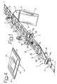
- Figure 1 is a general perspective view of part of a production system that may be used to make packs according to the present invention.
- Figure 2 is a view illustrating at an enlarged scale and in greater detail the part of Figure 1 indicated by the arrow II, and
- Figures 3 and 4 illustrate as a whole the characteristics of the pack according to the present invention in two successive steps of the corresponding fabrication process and/or process of use.
- The figures of the attached drawings illustrate the possible application of the solution according to the invention to the making of packs P containing articles A consisting, in the example of embodiment illustrated, of sanitary articles, such as panty-liners.
- The solution according to the invention may, however, be used for making sanitary articles of different types (e.g., absorbent articles of various nature, including medical articles), it remaining understood that the aforesaid articles need to be foldable according to a general C conformation, i.e., with the formation of a central branch and two end branches, the first folded against the central branch and the second folded against the first end branch.
- As viewed in Figure 1, the articles A are supposed as being fed (with known means that are not illustrated) in a continuous flow comprising articles A which move forward set sideways on (i.e., with their direction of greater extension orthogonal to the direction of feed) and with a given pitch between each one (for example, in the region of 7-14 cm). As viewed in Figure 1, the said forward movement takes place from right to left and top to bottom.
- At a point corresponding to a fitting station, designated as a whole by 1, there is made to converge towards the flow of articles A a web of sheet material F consisting typically of a strip of plastic material, such as polyethylene film.
- At a point corresponding to the position of convergence with the articles A, the film F is fed forwards (by motor-powered means, which are not illustrated but of a known type, e.g., motor-driven rollers) so as to advance at the same speed as that of the flow of articles A.
- Means for drawing along (consisting, for example, of a motor-driven conveyor belt 2 of a known type) act on the articles A from the opposite side to the one on which the film F is set. Once the articles A have been fitted to the film F, they thus advance with complete synchronism with the film F, hence in conditions of absence of relative movement with respect to the film F, all this being achieved without the need to resort, in order to obtain the desired result, to positive forms of connection involving the application of adhesive material between the articles A and the film F.
- In such conditions, the film F and the articles A are fed towards a forming
device 3, which is also of a type as a whole known: forming devices of this type are currently present, for instance, in the packaging machines of the type currently referred to as flow-pack in order to enclose the packaging film in the form of a cylinder. In the formingdevice 3 the longitudinal margins F1 of the film F are turned up and folded against the central portion of the film F, in such a way that the homologous ends of the articles A are entrapped and withheld against the central portion of the film F by the aforesaid turned-up longitudinal margins F1. - The composite ribbon-like element thus obtained, consisting of the film F with the margins F1 turned up against the central portion and of the articles A set thereon with the ends withheld by the aforesaid longitudinal margins, is fed towards a
sealing assembly 5. This takes place in such a way that the conveyor means 2 continue to act on the articles A in an area corresponding to the central portion of the latter. - The function of the sealing assembly 5 (also of a generally known type; for instance, it may be a set of counter-rotating jaws, basically resembling the ones used for forming the end sealing lines of the flow-pack packaging machines referred to previously) is that of forming, on both sides of each of the end parts of the articles A, two connection areas; for instance, these may be two sealing lines F2 (see, in particular, Figure 2). The lines F2 are designed to constitute a stable connection of the margins F1 to the central part of the film F against which the aforesaid margins F1 have previously been folded in the forming
device 3. - The result that may be obtained from the action of connection described is that each article A presents itself with its two ends inserted and withheld in corresponding pocket parts, with each pocket part defined by:
- a respective margin portion F1 comprised between two successive connection lines F2, and
- the homologous portion of the central part of the film F on which the said margin has previously been folded.
- The articles A may therefore be released from the conveying means 2, which do not usually extend beyond the
sealing station 5. From this point on, the articles A are in fact firmly withheld on the film F and can thus move together with the film F itself, which is fed along by known motor-driven means, not specifically illustrated in the drawings. - The foregoing is obtained without any need for the application of adhesive material.
- The perspective view presented in Figure 1 provides a better illustration of the fact that the
sealing station 5 preferably comprises, on either side of the path of advance of the film F, a pair of counter-rotating sealing jaws driven by motor means (not specifically illustrated, but of a known type) which operate in a synchronized way with the movement of feeding of the articles A and of the film F. - Again from Figure 1 it will further be noted that at least two
jaws 50 designed to operate on the top face of the film F are installed according to a general cantilever arrangement, hence without the presence of elements of interconnection, such as the shaft (not visible in the figure) which instead connects the homologous jaws, designated by 52, designed to act on the bottom face of the film F. - The fact that the
jaws 50 are installed in cantilever fashion thus enables the drawing means 2 to extend as far as the area in which the articles A are firmly received within the pocket formations referred to previously. - The solution described presents the advantage of ensuring exact positioning of the articles in the region where the
sealing station 5 acts, preventing the jaws of the sealing station from accidentally acting in an undesired way on the ends of the articles A, an eventuality that could accidentally occur in the absence of a positive guiding action (or more precisely an accompanying action) on the articles A of the type exerted by the means 2. - Downstream of the
station 5, the pack-forming process proceeds with operations that basically resemble those adopted in the known art for making the known packs to which reference was made in the introductory part of the present description. - In practice, the composite ribbon or web formed by the film F and by the articles A (having their ends inserted in the pocket formations created in the film F itself) is sent on to a further forming assembly 6 in which an end branch P1 of said composite ribbon is folded against the central branch P2 of the ribbon and, subsequently, the other end branch P3 is folded against the branch P1 so as to complete closing of the pack according to a general C conformation. For simplicity of illustration and in view of its notoriety (it is the same device used for bending into a C shape the packs of a known type to which reference was made in the introductory part of the present description) the presence of the forming assembly 6 has been recalled here in an altogether schematic way, where the successive steps of intervention of the device are represented by the
arrows - In a further sealing and cutting station, designated by 7, which also normally comprises one or more pairs of counter-rotating jaws, the film folded in a C configuration undergoes an operation of sealing and cutting in areas between successive articles A, the aim being to obtain individual packs corresponding to the pack P represented in Figure 3 (in a half-opened condition) and in Figure 4 (in a closed condition).
- The pack P thus comprises the article A set with its ends inserted in the pockets formed, according to the criteria described previously, by the margins F1 folded against the central part of the film, the aforesaid pockets being closed at the sides by the connection lines F2.
- The assembly thus obtained is folded according to a general C configuration with:
- a central branch P2 consisting of the median part of the film F and of the central part of the article A;
- a first end branch P1, comprising a first end of the article A received in a corresponding pocket, folded against the central branch P2; and
- a second end branch P3, comprising the other end of the article A received in a corresponding pocket, folded against the end branch P1.
- The above arrangement is obtained with the aforesaid pack withheld in a closed condition as a result of the connection (typically obtained by heat sealing of the film F in the station 7) of the edges G of the aforesaid portions P1, P2 and P3 extending in the direction of greater extension of the article A.
- In use, the user takes out the closed pack (Figure 4), raises the branch P3 away from the branch P1 (see Figure 3), and then raises the branch P1 thus uncovered from the branch P2, in so doing gradually separating the parts of the film element F connected along the edges G.
- In this way the article A is directly accessible so that it can be taken out of the pack. The article A may in fact be easily taken out of the pack, for instance by inserting a finger between the central portion of the article A and the homologous portion of the film element of the pack made up of the film F and then sliding the ends of the article A out of the corresponding receiving pockets.
- This result is achieved avoiding adhesive connection of the articles A to the film F, even though, of course, the article A may have on one of its sides an adhesive coating designed to enable a firmer connection of the article A to the garment on which the article A is to be worn. The aforesaid adhesive coating is in turn protected by a selectively removable strip, for example a strip of siliconized paper.
- It will be appreciated that the above coating and the corresponding strip or protection label do not necessarily have to be applied on the side of the article A designed to be set facing the film F.
- The solution according to the invention in fact makes it possible to set the article A in such a way that the aforesaid adhesive coating and the corresponding strip are located on the side of the article A opposite to the film F.
- The above location of the adhesive coating and corresponding strip may prove advantageous for at least two reasons, as described below.
- In the first place it enables a faster access to the strip (which is to be removed) when the pack is opened and the article taken out.
- In the second place, with this arrangement, the side of the article A opposite to the strip (i.e., the side which, in use, is to face the body of the user) remains applied against the film F up to the moment when the article A is taken out of the pack, with the result that it is better protected.
- For making the film F it is possible to use any plastic strip-like material which can be manipulated (i.e., shaped, sealed, etc.) in the way described, without it having to present characteristics and/or undergo processes such as to enable easy detachment of the article A, possibly preventing the formation of residue of adhesive.
- The article A can be removed from the pack just by sliding it out, hence avoiding the generation of any noise of tearing or detachment, and the film part of the pack is directly re-usable for receiving a used article, which is to be disposed of.
- Furthermore, it will be appreciated that in the closed pack P the end of the article A corresponding to the branch P3 is in any case inserted in the corresponding pocket formed by the film F and is thus protected against the possible penetration of contaminating agents from outside, all this without requiring the additional connection of the distal margin of the branch P3 to the first branch P1 (for instance, with the application of an adhesive layer).
- Of course, without prejudice to the principle of the invention, the details of construction and the embodiments may vary widely with respect to what is described and illustrated herein, without thereby departing from the scope of the present invention. This applies in particular, but without limitation, to the modalities for making the connection formations represented in the example illustrated by the lines F2. These lines may be produced by sealing (e.g., heat sealing), gluing or equivalent techniques, in a continuous or discontinuous way, with a more or less marked extension according to the specific applicational requirements. In particular, each pair of lines F2 located in a position immediately adjacent to one another without interposition of an article A (hence two lines F2 designed to define distinct corresponding pockets for receiving two successive articles A arriving one after the other in the flow) may be formed starting from a single area of sealing which is subsequently divided into two parts at the moment of separation of two successive packs.
Claims (17)
- A pack comprising an article (A) applied on a sheet or film element (F) , the assembly formed by the article (A) and by the film element (F) comprising a central branch (P2) as well as a first end branch (P1) and a second end branch (P3), and being foldable according to a general C conformation, with said first end branch (P1) folded against said central branch (P2) and said second end branch (P3) folded against said first branch (P1), which is in turn folded against said central branch (P2), characterized in that said film element (F) comprises, in areas corresponding to said end branches (P1, P3), pocket formations in which the homologous ends of said article (A) are received.
- The pack according to Claim 1, characterized_in that said article (A) is a sanitary product such as a panty-liner.
- The pack according to Claim 1 or Claim 2, characterized in that said article (A) is withheld on said film element (F) as a result of the location of said homologous ends in said pocket formations, in the substantial absence of adhesive connection between said article (A) and said film element (F).
- The pack according to any one of the preceding claims, characterized in that said article (A) carries applied to it a protective strip, said protective strip being selectively removable from said article (A).
- The pack according to Claim 4, characterized in that between said article (A) and said protective strip there is interposed an adhesive layer.
- The pack according to any one of the preceding claims, characterized in that said pocket formations are made up of margins (F1) of said film element (F) which are folded against the film element (F) itself.
- The pack according to Claim 6, characterized in that said margins (F1) are connected to said film element by means of connection formations (F2), preferably in the form of lines.
- The pack according to any one of the preceding claims, characterized in that with said pack folded according to said C conformation, said second end branch (P3) is connected to said first end branch (P) P1) in the substantial absence of connection elements between the distal margin of said second end branch (P3) and said first end branch (P1).
- A process for making a pack (P) comprising an article (A) applied on a strip element (F), the assembly formed by the article (A) and by the film element (F) comprising a central branch (P2) as well as a first end branch (P1) and a second end branch (P3) and being foldable according to a general C conformation, with said first end branch (P1) folded against said central branch (P2) and said second end branch (P3) folded against said first branch (P1), which is folded against said central branch (P2), characterized in that it comprises the operation of making in said film element (F), in areas corresponding to said end branches (P1, P3), pocket formations in which the homologous ends of said article (A) are received.
- The process according to Claim 9, characterized in that said article (A) is chosen as a sanitary product such as a panty-liner.
- The process according to Claim 9 or Claim 10, characterized in that it comprises the operation of placing said corresponding homologous ends in said pocket formations, in the substantial absence of adhesive connection between said article (A) and said film element (F).
- The process according to any one of the preceding claims from Claim 9 to Claim 11, characterized in that it comprises the operation of applying to said article (A) a protective strip, said protective strip being selectively removable from said article (A).
- The process according to Claim 12, characterized in that it comprises the operation of interposing an adhesive connection layer between said article (A) and said protective strip.
- The process according to any one of the preceding claims from Claim 9 to Claim 13, characterized in that it comprises the operation of forming said pocket formations by folding (3) margins (F1) of said film element (F) against the film element (F) itself.
- The process according to Claim 14, characterized in that it comprises the operation of connecting said margins (F1) to the body of said film element (F1), preferably by sealing.
- The process according to any one of the preceding claims from Claim 9 to Claim 15, characterized in that it is carried out on a flow of said articles (A) as they are moving and comprises the operation of positively controlling (2) the movement of said articles (A) until said pocket formations are made.
- A process according to Claim 16, characterized in that said pocket formations are formed by acting on said opposed margins (F1) of said film element (F) with connecting elements (5) mounted, at least in part (50), according to a general cantilever configuration with respect to said first film element (F), and in that it comprises the operation of providing means (3) for positive conveying of said articles (A) extending in a position between said connecting elements (5) arranged at least in part (50) in cantilever fashion.
Applications Claiming Priority (2)
| Application Number | Priority Date | Filing Date | Title |
|---|---|---|---|
| IT2000TO000465A IT1320195B1 (en) | 2000-05-23 | 2000-05-23 | PACKAGING FOR SANITARY AND SANITARY ITEMS AND RELATED MANUFACTURING PROCEDURE. |
| ITTO000465 | 2000-05-23 |
Publications (2)
| Publication Number | Publication Date |
|---|---|
| EP1157680A1 true EP1157680A1 (en) | 2001-11-28 |
| EP1157680B1 EP1157680B1 (en) | 2004-07-28 |
Family
ID=11457740
Family Applications (1)
| Application Number | Title | Priority Date | Filing Date |
|---|---|---|---|
| EP01830052A Expired - Lifetime EP1157680B1 (en) | 2000-05-23 | 2001-01-26 | A package for sanitary articles and corresponding manufacturing method |
Country Status (3)
| Country | Link |
|---|---|
| EP (1) | EP1157680B1 (en) |
| DE (1) | DE60104478T2 (en) |
| IT (1) | IT1320195B1 (en) |
Cited By (8)
| Publication number | Priority date | Publication date | Assignee | Title |
|---|---|---|---|---|
| EP1400223A1 (en) * | 2002-09-17 | 2004-03-24 | Winkler + Dünnebier Aktiengesellschaft | Packed hygiene product for acquiring body fluids and method of producing such a product |
| EP1407747A1 (en) * | 2002-10-09 | 2004-04-14 | Zuiko Corporation | Absorbent article |
| EP2279717A3 (en) * | 2009-07-30 | 2013-04-03 | McNeil-PPC, Inc. | Individually packaged absorbent article assembly, method of packaging an absorbent article and method of attaching the absorbent article to an undergarment |
| US8545470B2 (en) | 2009-07-30 | 2013-10-01 | Mcneil-Ppc, Inc. | Method of packaging an absorbent article and attaching the absorbent article to an undergarment |
| US8568378B2 (en) | 2009-07-30 | 2013-10-29 | Mcneill-Ppc, Inc. | Method of packaging an absorbent article and attaching the absorbent article to an undergarment |
| US8932272B2 (en) | 2009-07-30 | 2015-01-13 | Mcneil-Ppc, Inc. | Individually packaged absorbent article assembly |
| US9011400B2 (en) | 2009-07-30 | 2015-04-21 | Mcneil-Ppc, Inc. | Individually packaged absorbent article assembly |
| EP3437597A4 (en) * | 2016-03-28 | 2019-04-24 | Unicharm Corporation | Method for manufacturing and device for manufacturing package for absorbent article |
Citations (3)
| Publication number | Priority date | Publication date | Assignee | Title |
|---|---|---|---|---|
| JPH03176376A (en) * | 1989-11-28 | 1991-07-31 | Dainippon Printing Co Ltd | Wrapping of sanitary napkin |
| JPH08224269A (en) * | 1995-02-23 | 1996-09-03 | Kao Corp | Discrete package for sanitary napkin and its production |
| JPH09215707A (en) * | 1996-02-08 | 1997-08-19 | Toa Kiko Kk | Packaging device for sanitary goods and its packaging method |
-
2000
- 2000-05-23 IT IT2000TO000465A patent/IT1320195B1/en active
-
2001
- 2001-01-26 DE DE2001604478 patent/DE60104478T2/en not_active Expired - Lifetime
- 2001-01-26 EP EP01830052A patent/EP1157680B1/en not_active Expired - Lifetime
Patent Citations (3)
| Publication number | Priority date | Publication date | Assignee | Title |
|---|---|---|---|---|
| JPH03176376A (en) * | 1989-11-28 | 1991-07-31 | Dainippon Printing Co Ltd | Wrapping of sanitary napkin |
| JPH08224269A (en) * | 1995-02-23 | 1996-09-03 | Kao Corp | Discrete package for sanitary napkin and its production |
| JPH09215707A (en) * | 1996-02-08 | 1997-08-19 | Toa Kiko Kk | Packaging device for sanitary goods and its packaging method |
Non-Patent Citations (3)
| Title |
|---|
| PATENT ABSTRACTS OF JAPAN vol. 015, no. 416 (M - 1172) 23 October 1991 (1991-10-23) * |
| PATENT ABSTRACTS OF JAPAN vol. 1997, no. 01 31 January 1997 (1997-01-31) * |
| PATENT ABSTRACTS OF JAPAN vol. 1997, no. 12 25 December 1997 (1997-12-25) * |
Cited By (11)
| Publication number | Priority date | Publication date | Assignee | Title |
|---|---|---|---|---|
| EP1400223A1 (en) * | 2002-09-17 | 2004-03-24 | Winkler + Dünnebier Aktiengesellschaft | Packed hygiene product for acquiring body fluids and method of producing such a product |
| EP1407747A1 (en) * | 2002-10-09 | 2004-04-14 | Zuiko Corporation | Absorbent article |
| EP2279717A3 (en) * | 2009-07-30 | 2013-04-03 | McNeil-PPC, Inc. | Individually packaged absorbent article assembly, method of packaging an absorbent article and method of attaching the absorbent article to an undergarment |
| US8545470B2 (en) | 2009-07-30 | 2013-10-01 | Mcneil-Ppc, Inc. | Method of packaging an absorbent article and attaching the absorbent article to an undergarment |
| US8568378B2 (en) | 2009-07-30 | 2013-10-29 | Mcneill-Ppc, Inc. | Method of packaging an absorbent article and attaching the absorbent article to an undergarment |
| US8932272B2 (en) | 2009-07-30 | 2015-01-13 | Mcneil-Ppc, Inc. | Individually packaged absorbent article assembly |
| US9011400B2 (en) | 2009-07-30 | 2015-04-21 | Mcneil-Ppc, Inc. | Individually packaged absorbent article assembly |
| US9011399B2 (en) | 2009-07-30 | 2015-04-21 | Mcneil-Ppc, Inc. | Method of packaging an absorbent article and attaching the absorbent article to an undergarment |
| AU2010202749B2 (en) * | 2009-07-30 | 2015-06-11 | Mcneil-Ppc, Inc. | Individually packaged absorbent article assembly |
| US9211219B2 (en) | 2009-07-30 | 2015-12-15 | Johnson & Johnson Consumer Inc. | Method of packaging an absorbent article and attaching the absorbent article to an undergarment |
| EP3437597A4 (en) * | 2016-03-28 | 2019-04-24 | Unicharm Corporation | Method for manufacturing and device for manufacturing package for absorbent article |
Also Published As
| Publication number | Publication date |
|---|---|
| DE60104478D1 (en) | 2004-09-02 |
| ITTO20000465A1 (en) | 2001-11-23 |
| DE60104478T2 (en) | 2005-01-13 |
| IT1320195B1 (en) | 2003-11-26 |
| EP1157680B1 (en) | 2004-07-28 |
| ITTO20000465A0 (en) | 2000-05-23 |
Similar Documents
| Publication | Publication Date | Title |
|---|---|---|
| US4402453A (en) | Pouch with closure seal strip and method for making same | |
| US5429576A (en) | Apparatus for making reusable adhesive envelopes | |
| US6978584B1 (en) | Multiple lane packaging of feminine sanitary articles and resulting product | |
| US5454207A (en) | Applicator mitt | |
| EP2077946B1 (en) | Method of making bag with interrupted side gussets | |
| CN101909868B (en) | Bag-making machine | |
| US4174597A (en) | Process for wrapping articles and providing reclosable container | |
| US20090232425A1 (en) | Flexible Tubular Packaging Bag and Method and Apparatus for Making the Same | |
| US11208248B2 (en) | Container for smoking articles | |
| US3693867A (en) | Handle-type carrying bag made of plastics material sheeting | |
| EP1157680B1 (en) | A package for sanitary articles and corresponding manufacturing method | |
| US20100310195A1 (en) | Layered bag with re-sealable closure assembly | |
| US4235337A (en) | Rapidly opening sealed package for wound dressing adhesive tape | |
| US3022613A (en) | Packaging method | |
| US5584163A (en) | Applicator mitt | |
| US2325673A (en) | Tobacco pouch and method of making same | |
| US3439468A (en) | Method of manufacturing bag closures | |
| JP2005263300A (en) | Packaging bag with fastener, manufacturing method for it, and fastener mounting device | |
| JP5797970B2 (en) | Packaging body and packaging machine | |
| JP7292443B1 (en) | Paper bag manufacturing method | |
| WO1983004011A1 (en) | Method and apparatus for continuous formation of reclosable article wrappers | |
| JPH11321817A (en) | Carton sealer | |
| CN210794179U (en) | PE food packaging bag | |
| JP7061313B2 (en) | Packaging bag and packaging machine | |
| JP3004873U (en) | Envelope |
Legal Events
| Date | Code | Title | Description |
|---|---|---|---|
| PUAI | Public reference made under article 153(3) epc to a published international application that has entered the european phase |
Free format text: ORIGINAL CODE: 0009012 |
|
| AK | Designated contracting states |
Kind code of ref document: A1 Designated state(s): AT BE CH CY DE DK ES FI FR GB GR IE IT LI LU MC NL PT SE TR Kind code of ref document: A1 Designated state(s): DE |
|
| AX | Request for extension of the european patent |
Free format text: AL;LT;LV;MK;RO;SI |
|
| 17P | Request for examination filed |
Effective date: 20011219 |
|
| AKX | Designation fees paid |
Free format text: DE |
|
| GRAP | Despatch of communication of intention to grant a patent |
Free format text: ORIGINAL CODE: EPIDOSNIGR1 |
|
| GRAS | Grant fee paid |
Free format text: ORIGINAL CODE: EPIDOSNIGR3 |
|
| GRAA | (expected) grant |
Free format text: ORIGINAL CODE: 0009210 |
|
| AK | Designated contracting states |
Kind code of ref document: B1 Designated state(s): DE |
|
| REF | Corresponds to: |
Ref document number: 60104478 Country of ref document: DE Date of ref document: 20040902 Kind code of ref document: P |
|
| PLBE | No opposition filed within time limit |
Free format text: ORIGINAL CODE: 0009261 |
|
| STAA | Information on the status of an ep patent application or granted ep patent |
Free format text: STATUS: NO OPPOSITION FILED WITHIN TIME LIMIT |
|
| 26N | No opposition filed |
Effective date: 20050429 |
|
| PGFP | Annual fee paid to national office [announced via postgrant information from national office to epo] |
Ref country code: DE Payment date: 20180329 Year of fee payment: 18 |
|
| REG | Reference to a national code |
Ref country code: DE Ref legal event code: R119 Ref document number: 60104478 Country of ref document: DE |
|
| PG25 | Lapsed in a contracting state [announced via postgrant information from national office to epo] |
Ref country code: DE Free format text: LAPSE BECAUSE OF NON-PAYMENT OF DUE FEES Effective date: 20190801 |