EP1156671A2 - Audio/video apparatus - Google Patents
Audio/video apparatus Download PDFInfo
- Publication number
- EP1156671A2 EP1156671A2 EP01304429A EP01304429A EP1156671A2 EP 1156671 A2 EP1156671 A2 EP 1156671A2 EP 01304429 A EP01304429 A EP 01304429A EP 01304429 A EP01304429 A EP 01304429A EP 1156671 A2 EP1156671 A2 EP 1156671A2
- Authority
- EP
- European Patent Office
- Prior art keywords
- module
- function
- extending
- data
- unit
- Prior art date
- Legal status (The legal status is an assumption and is not a legal conclusion. Google has not performed a legal analysis and makes no representation as to the accuracy of the status listed.)
- Withdrawn
Links
Images


Classifications
-
- H—ELECTRICITY
- H04—ELECTRIC COMMUNICATION TECHNIQUE
- H04N—PICTORIAL COMMUNICATION, e.g. TELEVISION
- H04N21/00—Selective content distribution, e.g. interactive television or video on demand [VOD]
- H04N21/40—Client devices specifically adapted for the reception of or interaction with content, e.g. set-top-box [STB]; Operations thereof
- H04N21/41—Structure of client; Structure of client peripherals
- H04N21/418—External card to be used in combination with the client device, e.g. for conditional access
- H04N21/4183—External card to be used in combination with the client device, e.g. for conditional access providing its own processing capabilities, e.g. external module for video decoding
-
- H—ELECTRICITY
- H04—ELECTRIC COMMUNICATION TECHNIQUE
- H04N—PICTORIAL COMMUNICATION, e.g. TELEVISION
- H04N5/00—Details of television systems
- H04N5/44—Receiver circuitry for the reception of television signals according to analogue transmission standards
-
- H—ELECTRICITY
- H04—ELECTRIC COMMUNICATION TECHNIQUE
- H04N—PICTORIAL COMMUNICATION, e.g. TELEVISION
- H04N21/00—Selective content distribution, e.g. interactive television or video on demand [VOD]
- H04N21/40—Client devices specifically adapted for the reception of or interaction with content, e.g. set-top-box [STB]; Operations thereof
- H04N21/41—Structure of client; Structure of client peripherals
- H04N21/414—Specialised client platforms, e.g. receiver in car or embedded in a mobile appliance
- H04N21/4147—PVR [Personal Video Recorder]
-
- H—ELECTRICITY
- H04—ELECTRIC COMMUNICATION TECHNIQUE
- H04N—PICTORIAL COMMUNICATION, e.g. TELEVISION
- H04N21/00—Selective content distribution, e.g. interactive television or video on demand [VOD]
- H04N21/40—Client devices specifically adapted for the reception of or interaction with content, e.g. set-top-box [STB]; Operations thereof
- H04N21/41—Structure of client; Structure of client peripherals
- H04N21/418—External card to be used in combination with the client device, e.g. for conditional access
- H04N21/4184—External card to be used in combination with the client device, e.g. for conditional access providing storage capabilities, e.g. memory stick
-
- H—ELECTRICITY
- H04—ELECTRIC COMMUNICATION TECHNIQUE
- H04N—PICTORIAL COMMUNICATION, e.g. TELEVISION
- H04N21/00—Selective content distribution, e.g. interactive television or video on demand [VOD]
- H04N21/40—Client devices specifically adapted for the reception of or interaction with content, e.g. set-top-box [STB]; Operations thereof
- H04N21/41—Structure of client; Structure of client peripherals
- H04N21/426—Internal components of the client ; Characteristics thereof
-
- H—ELECTRICITY
- H04—ELECTRIC COMMUNICATION TECHNIQUE
- H04N—PICTORIAL COMMUNICATION, e.g. TELEVISION
- H04N21/00—Selective content distribution, e.g. interactive television or video on demand [VOD]
- H04N21/40—Client devices specifically adapted for the reception of or interaction with content, e.g. set-top-box [STB]; Operations thereof
- H04N21/45—Management operations performed by the client for facilitating the reception of or the interaction with the content or administrating data related to the end-user or to the client device itself, e.g. learning user preferences for recommending movies, resolving scheduling conflicts
- H04N21/462—Content or additional data management e.g. creating a master electronic programme guide from data received from the Internet and a Head-end or controlling the complexity of a video stream by scaling the resolution or bit-rate based on the client capabilities
- H04N21/4622—Retrieving content or additional data from different sources, e.g. from a broadcast channel and the Internet
-
- H—ELECTRICITY
- H04—ELECTRIC COMMUNICATION TECHNIQUE
- H04N—PICTORIAL COMMUNICATION, e.g. TELEVISION
- H04N21/00—Selective content distribution, e.g. interactive television or video on demand [VOD]
- H04N21/40—Client devices specifically adapted for the reception of or interaction with content, e.g. set-top-box [STB]; Operations thereof
- H04N21/47—End-user applications
- H04N21/485—End-user interface for client configuration
-
- H—ELECTRICITY
- H04—ELECTRIC COMMUNICATION TECHNIQUE
- H04N—PICTORIAL COMMUNICATION, e.g. TELEVISION
- H04N5/00—Details of television systems
- H04N5/76—Television signal recording
- H04N5/765—Interface circuits between an apparatus for recording and another apparatus
- H04N5/775—Interface circuits between an apparatus for recording and another apparatus between a recording apparatus and a television receiver
-
- A—HUMAN NECESSITIES
- A63—SPORTS; GAMES; AMUSEMENTS
- A63F—CARD, BOARD, OR ROULETTE GAMES; INDOOR GAMES USING SMALL MOVING PLAYING BODIES; VIDEO GAMES; GAMES NOT OTHERWISE PROVIDED FOR
- A63F2300/00—Features of games using an electronically generated display having two or more dimensions, e.g. on a television screen, showing representations related to the game
- A63F2300/20—Features of games using an electronically generated display having two or more dimensions, e.g. on a television screen, showing representations related to the game characterised by details of the game platform
- A63F2300/206—Game information storage, e.g. cartridges, CD ROM's, DVD's, smart cards
-
- H—ELECTRICITY
- H04—ELECTRIC COMMUNICATION TECHNIQUE
- H04N—PICTORIAL COMMUNICATION, e.g. TELEVISION
- H04N5/00—Details of television systems
- H04N5/64—Constructional details of receivers, e.g. cabinets or dust covers
Definitions
- the present invention relates to an audio and/or video apparatus comprising output means for producing a perceivable output signal in dependence on an input signal, a plurality of sources of content signals for controlling the output means and control means for selectively applying content signals from said sources to the output means.
- Digital terrestrial broadcasting which complies with the Advanced Television Systems Committee (ATSC) standards has begun.
- Consumer electronics product manufacturers are disclosing various digital media products, including digital televisions capable of receiving digital broadcasts and digital versatile disc (DVD) players and digital video recorders capable of recording and reproducing digital broadcasts.
- digital televisions capable of receiving digital broadcasts
- DVD digital versatile disc
- digital video recorders capable of recording and reproducing digital broadcasts.
- New digital media products such as digital broadcast receiving apparatuses, satellite broadcast receiving apparatuses, DVD players, hard disc drives and Internet access apparatuses, increase the number of manipulation methods a user has to learn and the number of remote controllers.
- a user has to pay a lot of money to buy digital media products.
- the digital media products take up a large amount of space in the home and each digital media product needs a power line for operation.
- the product For operating a product that reproduces images displayed on a digital TV, such as a DVD player, the product needs to be be connected to a digital TV using an electric lead.
- the appearance of digital media products has made it possible to have a home network connecting multiple home appliances in a house. If the home network is implemented, a user can control multiple appliances in the house with only one apparatus. In addition, the user can control the appliances in the house through the Internet even when the user is in a remote place.
- a known example of a multifunction audio/video device is a combined television and video cassette recorder.
- An apparatus is characterised in that one of said sources comprises a module releasably mounted at a mechanical mounting point of a main part of said apparatus, the module and mounting point including means for the communication, for example by electric or electromagnetic means, of content signals and control signals between said module and said control and output means.
- the term "content” is used to indicate signals that define the what is to be perceived, e.g. still images, video, music, animation, game scenes etc..
- a plurality of mounting points for modules constituting sources of content signals are provided.
- the mounting points may comprise slots in a rack-like structure.
- the control means is configured for routing content signals between modules, e.g. for recording video signals from a broadcast TV receiving module in a DVD recording module.
- the output means includes a display means
- the or each module includes means for sending control signals comprising markup language codes to the control means and the control means is responsive to said markup language codes to generate an image on the display means.
- said image constitutes part of a user interface for controlling the respective module and the control means is responsive to operation of user input means in the context of a displayed image to generate control signals for the respective module.
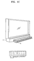
- a modular TV system has a display device 18 supported by a TV stand 10.
- the display device 18 may be a cathode-ray tube (CRT), a ferroelectric LCD (FLCD), a field emission display (FED), or a plasma display panel (PDP).
- a module rack 16 is installed in the middle of the TV stand 10 under the display device 18, and speakers 12 are installed to the right and left of the module rack 16.
- a door which is opened and closed by sliding or rotating is attached to the module rack 16.
- a plurality of module-receiving holes are formed in the front of the module rack 16 which is exposed to the outside when the door 14 is open.
- a digital video cassette recorder (DVCR) module is inserted into the uppermost module-receiving hole.
- the DVCR has a hole 17 for receiving a digital video tape.
- the DVCR module is an example of a function-extending module.
- module-receiving holes may be formed in a horizontal row so that a plurality of function-extending modules can be inserted in a row.
- Function-extending modules are for extending the functions of the modular TV system. For example, if a user buys a DVD module and installs the DVD module in the module rack 16, the modular TV system will have a DVD player function.
- a base module (not shown) is installed at the back of the module rack 16.
- the base module communicates control signals with the function-extending modules in a client-server fashion. That is, the base module receives control information from the function-extending modules, inserted into the module rack 16, and outputs and displays the received control information on the display device 18. If a user input corresponding to the displayed control information is received, the base module sends the user input to one of the function-extending modules. In response to the input information, the function-extending module sends A/V data to the base module. The base module processes the received A/V data and then outputs the A/V data to the display device 18 and/or the speakers 12.
- the function-extending module stores an index page containing control information for controlling itself and the base module has a browser for selecting a function-extending module.
- the browser displays a main page, in which selection information for at least one or more function-extending modules is contained, for the user.
- the browser requests an index page from a function-extending module selected by the user through the main page, and displays the index page to the user. If the user inputs a control command through the displayed index page, the browser sends the control command again to the function-extending module.
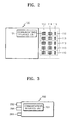
- the base module 100 has a plurality of connectors 110 for module connection.
- Each connector 110 contains two communications ports 112, 114 and one power connection port 116.
- the two communications ports 112, 114 and the power connection port 116 are designed so that each function-extending module can be easily inserted and connected into a module-receiving hole (not shown) of the module rack 16.
- a function-extending module 200 also has two communications ports 292, 294 and one power connection port 296. Since the function-extending module 200 is in a casing, the communications ports 292, 294 and power connection port 296 are formed so as to protrude from the casing. Therefore, if the function-extending module 200 is inserted into a module-receiving hole formed in the module rack 16, the corresponding ports contact each other and the base module 100 and the function-extending module 200 are electrically connected. Also, if a plurality of function-extending modules 200 are inserted into the module rack 16, the plurality of function-extending modules are connected to the base module 100 in a daisy-chain fashion.
- the method for connecting the base module 100 to the plurality of function-extending modules 200 may be determined in various ways as needed.
- communications ports 112, 114 of the base module 100 and communications ports 292, 294 of the function-extending module are electrically connected to their own communications interface units 101, 201.
- Each of the communications interface units 101, 201 may be implemented as an IEEE 1394 interface unit complying with the IEEE 1394 protocol.
- the communications interface units 101, 201 can be connected through a universe serial bus (USB), a peripheral interconnect (PCI) bus, or a Fast-Ethernet.
- USB universe serial bus
- PCI peripheral interconnect
- Fast-Ethernet Fast-Ethernet
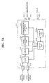
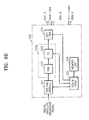
- a base module 100 has a communications interface unit 101, a signal processing unit 110, a video processing unit 104, an audio processing unit 105, a user input unit 106, a memory unit 107, and a control unit 108.
- the memory unit 107 includes a RAM, ROM, and a flash memory depending on the embodiment of the present invention.
- the RAM is used as a buffer for processing image data which forms a main page to be explained later
- the ROM stores a browser for searching for a function-extending module 200
- the flash memory stores the Internet protocol (IP) address of the function-extending module 200.
- IP Internet protocol
- the user input unit 106 receives user inputs, which are input through a command key (not shown) or a remote controller, and sends the user inputs to the control unit 108.
- the communications interface unit 101 communicates data with the outside.
- the A/V data which is received through the communications interface unit 101, is divided into video data and audio data, processed, and then the video data and audio data are output to the video processing unit 104 and the audio processing unit 105 respectively.
- the video processing unit 104 processes the video data output from the signal processing unit 110 and sends the video data to the display device 18, and the audio processing unit processes the audio data output from the signal processing unit 110 and sends the audio data to the speakers 12.
- the signal processing unit 110 has a transport stream processing unit 102 for demultiplexing the MPEG transport stream.
- the communications interface unit 101 is implemented as an IEEE 1394 interface unit 101b, the communications interface unit 101 sends and receives an MPEG transport stream, a state signal or a control signal, which are sent according to the IEEE 1394 protocol, and sends the MPEG transport stream to the transport stream processing unit 102 and state and control signals to the control unit 108.
- the mixing unit 103 generates an image or text information signal, which is input from the outside (a), or from the control unit 108 (b), overlays it onto a video signal (c), and outputs the overlayed signal to the video processing unit 104. By doing so, data, including caption data, can be displayed.
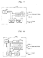
- the function-extending module 200 has a communications interface unit 201, a signal processing unit 203, a memory unit 204, and a control unit 205.
- the communications interface unit 201 communicates with the base module 100.
- the memory unit 204 stores an IP address assigned to the function-extending module 200, an index page, and a function-performing program needed to perform a function given to the function-extending module 200, and, when necessary, source A/V data.
- the signal processing unit 203 signal processes source A/V data and outputs the processed A/V data to the communications interface unit 201.
- the control unit 205 provides the IP address and index page to the base module 100, and responds to a user input, which is received by the base module 100, so that corresponding A/V data can be sent to the base module 100. Also, when necessary, the control unit 205 sends an install program, which the base module 100 requires to control the function-extending module 200, to the base module 100.
- the source A/V data is data that is requested by the user, and is provided to the function-extending module 200 from the outside or is stored in the memory unit 204 of the function-extending module 200.
- the type of source A/V data depends on the function of the function-extending module 200. If the function-extending module 200 is a DVD module for performing a DVD player function, the source A/V data is A/V data recorded on the DVD. If the function-extending module 200 is a hard disk drive (HDD) module, the source A/V data is data recorded on a hard disk.
- HDD hard disk drive
- the signal processing unit 203 processes signals appropriately depending on the characteristics of the source A/V data. For example, if the function-extending module 200 is a cable broadcast receiving module for receiving a cable broadcast signal, the signal processing unit 203 demodulates and decodes a cable broadcast signal received through a tuner. If the function-extending module 200 is a DVD module, the signal processing unit 203 decodes data read from a DVD and provides the decoded data to the communications interface unit 201, or encodes data provided by other function-extending modules and records the encoded data on a writeable DVD.
- the memory unit 204 has a RAM, a ROM, and a flash memory as the base module 100.
- the RAM may be used as a buffer.
- the ROM stores an application program so that the function-extending module 200 can operate as a server for the browser in the base module 100.
- the ROM stores an index page which is needed by the function-extending module 200 operating as a server to the base module 100.
- the flash memory stores an IP address assigned to the function-extending module 200.
- the control unit 205 operates the server stored in the ROM so that the function-extending module 200 communicates with the base module 100 in a client-server fashion.
- the signal processing unit 203 has a transport stream processing unit 202 which multiplexes or demultiplexes the MPEG transport stream.
- the communications interface unit 201 is implemented as an IEEE 1394 interface unit 201b, the communications interface unit 201 sends and receives an MPEG transport stream, a state signal or a control signal, which are sent according to the IEEE 1394 protocol.
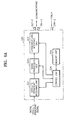
- a broadcast television receiving module 210 has a receiving terminal 211 for receiving a digital broadcast signal, a receiving terminal 212 for receiving a cable broadcast signal, a switching unit 213 for selecting one of the receiving terminals 211, 212, a tuner 214, a signal processing unit 210a, a communications interface unit 218, a memory unit 219a and a control unit 219.
- the broadcast receiving module 210 also has communications ports 292-1, 294-1 and a power connection port 296-1, which protrude from from the casing of the broadcast receiving module 210.
- the receiving terminals 211, 212 receive a digital broadcast signal and a cable broadcast signal transmitted from the outside.
- the switching unit 213 selects one of the receiving terminals 211, 212.
- the tuner 214 selects one of the digital broadcast signal and cable broadcast signal received through the receiving terminals 211, 212, respectively.
- the signal processing unit 210a processes the signal selected by the tuner 214 and outputs the signal to the communications interface unit 218.
- the communications interface unit 218 communicates with the base module 100.
- the memory unit 219a stores the assigned IP address and an index page.
- the control unit 219 provides the IP address and index page to the base module 100, and controls the communications interface unit 218 so that the transport stream, which is output from the signal processing unit 210a in response to a user input received by the base module 100, is sent to the base module 100 through the communications interface unit 218.
- the signal processing unit 210a has a channel decoder 215 for channel decoding, a card connection unit 216, and a transport stream processing unit 217 for demultiplexing a transport stream.
- the communications interface unit 218 may be implemented as an IEEE 1394 interface unit complying with the IEEE1394 protocol.
- the card connection unit 216 may be implemented as a point of deployment (POD) connection unit, into which a POD card for authenticating a user identification is inserted.
- the POD connection unit reads a user identification number from a POD card inserted by a user, and if the user is authenticated, it electrically connects the channel decoder 215 and the transport stream processing unit 217 so that the broadcast receiving module 210 can operate.
- POD point of deployment
- a digital broadcast module or a cable broadcast module may be separately implemented by making a digital broadcast receiving module with only a receiving terminal 211 for receiving a digital broadcast signal and without a switching unit 213, or by making a cable broadcast receiving module with only a receiving terminal 212 for receiving a cable broadcast signal and without a switching unit 213.
- a digital satellite broadcast receiving module 220 has a satellite broadcast receiving unit 221, a signal processing unit 220a, a communications interface unit 224, a memory unit 226, and a control unit 225.
- the digital satellite broadcast receiving module 220 also has communications ports 292-2, 294-2 and a power connection port 296-2, which protrude from the casing of the digital satellite broadcast receiving module 220.
- the digital satellite broadcast receiving unit 221 receives a digital satellite broadcast signal.
- the signal processing unit 220a processes the received digital satellite broadcast signal.
- the communications interface unit 224 communicates with the base module 100.
- the memory unit 226 stores an IP address and an index page.
- the control unit 225 provides the IP address and index page to the base module 100, and controls communications interface unit 224 so that a digital satellite broadcast signal, which corresponds to a user input received by the base module 100, is sent to the base module 100 through the communications interface unit 224.
- the signal processing unit 220a has a card connection unit 222 and a transport stream processing unit 223.
- the communications interface unit 224 may be implemented as an IEEE 1394 interface unit complying with the IEEE 1394 protocol.
- the card connection unit 222 can be implemented as the POD connection unit, which was explained with reference to Figure 5B.
- a hard disc drive module 230 has a hard disc drive 231, a communications interface unit 233, a memory unit 235, and a control unit 234.
- the hard disc drive module 230 also has communications ports 292-3, 294-3 and a power connection port 296-3, which protrude from the casing of the hard disc drive module 230.
- the memory unit 235 stores an IP address and an index page. In the index page, a GUI-type user interface for controlling the hard disc drive module 230 is displayed.
- the communications interface unit 233 communicates with the base module 100.
- the control unit 234 provides the IP address assigned to the hard disc drive module 230 and the index page to the base module 100, and controls the hard disc drive module 230 so that data recorded on the hard disc 231 is sent to the base module 100 through the communications interface unit 233 in response to a user input received by the base module 100.
- the communications interface unit 233 may be implemented as an IEEE 1394 interface unit complying with the IEEE 1394 protocol.
- a DVD module 240 has a deck unit 241, a signal processing unit 243, a communications interface unit 244, a memory unit 246 and a control unit 245. Also, the DVD module has communications ports 292-4, 294-4 and a power connection port 296-4, which protrude from the casing of the DVD module 240.
- a DVD is loaded into the deck unit 241 so that source A/V data can be read or recorded.
- the signal processing unit 243 reads source A/V data from the DVD mounted on the deck unit 241 and processes the data so as to reproduce it, or processes A/V data input from the outside so as to record it as source A/V data.
- the communications interface unit 244 communicates with the base module 100.
- the memory unit 246 stores an IP address and an index page. In the index page, a GUI-type user interface for controlling the DVD module 240 is defined.
- the control unit 245 provides the IP address and index page to the base module 100, and controls the deck unit 241, the signal processing unit 243 and the communications interface unit 244 so that source A/V data, which is read from the DVD in response to a user input received by the base module 100 and processed by the signal processing unit 243, is sent to the base module 100 through the communications interface unit 244.
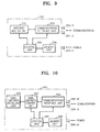
- an Internet access module 250 has an Internet access unit 251, a communications interface unit 254, a memory unit 256 and a control unit 255. Also, the Internet access module 250 has communications ports 292-5, 294-5 and a power connection port 296-5, which protrude from the casing of the Internet access module 250.
- the Internet access unit 251 provides access to the Internet.
- the communications interface unit 254 communicates with the base module 100.
- the memory unit 256 stores an IP address and an index page. In the index page, a GUI-type user interface for controlling the Internet access module 250 is defined.
- the control unit 255 provides the IP address and index page to the base module 100 and controls the Internet access unit 251 and the communications interface unit 254 so that a web page received through the Internet access unit 251, in response to a user input received by the base module 100, is sent to the base module 100 through the communications interface 254.
- the communications interface unit 254 may be implemented as an IEEE 1394 interface unit complying with the IEEE 1394 protocol.
- a USB bus or a PCI bus can be used or other communications protocols that support appropriate transmission speed with respect to A/V data to be transmitted, such as a Fast-Ethernet, can be adopted.
- a game module 260 has a game cartridge installing unit 262, a game cartridge control unit 263, a communications interface unit 264, a memory unit 266, and a control unit 265. Also, the game module has communications ports 292-6, 294-6, and a power connection port 296-6, which protrude from the casing of the game module 260.
- the game cartridge installing unit 262 a game cartridge is inserted.
- the game cartridge control unit 263 controls the game cartridge installing unit 262.
- the communications interface unit 264 communicates with the base module 100.
- the memory unit 266 stores an IP address and an index page. In the index page, a GUI-type user interface for controlling the game module 260 is defined.
- the control unit 265 provides the IP address and index page to the base module 100, and controls the game module 260 so that game contents stored in a game cartridge (not shown) are sent to the base module 100 through the communications interface unit 264.
- the communications interface unit 264 may be implemented as an IEEE 1394 interface unit complying with the IEEE 1394 protocol.
- a USB bus or a PCI bus can be connected, or other communications protocols that support appropriate transmission speed with respect to A/V data to be transmitted, such as a Fast-Ethernet, can be adopted.
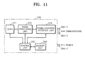
- a DVCR module 270 has a deck unit 271, a signal processing unit 273, a communications interface unit 274, a memory unit 276 and a control unit 275. Also, the DVCR module 270 has communications ports 292-7, 294-7 and a power connection port 296-7, which protrude from the casing of the DVCR module 270.
- a DVCR is mounted so that source A/V data can be read.
- the signal processing unit 273 reads source A/V data from the DVCR mounted on the deck unit 271 and processes the data.
- the communications interface unit 274 communicates with the base module 100.
- the memory unit 276 stores an IP address and an index page. In the index page, a GUI-type user interface for controlling the DVCR module 270 is defined.
- the control unit 275 provides the IP address and index page to the base module 100, and controls the deck unit 271, the signal processing unit 273, and the communications interface unit 274 so that source A/V data, which is read from the DVCR in response to a user input received by the base module 100 and processed by the signal processing unit 273, is sent to the base module 100 through the communications interface unit 274.
- the communications interface unit 274 may be implemented as an IEEE 1394 interface unit complying with the IEEE 1394 protocol.
- a USB bus or a PCI bus can be connected, or other communications protocols that support appropriate transmission speed with respect to A/V data to be transmitted, such as a Fast-Ethernet, can be adopted.
- data communications between the base module 100 and a function-extending module complies with the IEEE 1394 protocol.
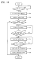
- the base module 100 determines whether or not any function-extending modules 200 are inserted into the module rack 16 in step 1304.
- Each inserted function-extending module 200 sends its index page to the base module 100, and the base module 100 installs the received index page in step 1306. At this time, the function-extending module 100 also sends its IP address and the base module 100 stores the received IP address. However, the step for sending and receiving the IP address may be performed independently from step 1306.
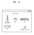
- the browser in the base module 100 begins to operate in step 1308, and displays a main page, as shown in Figure 14, in step 1310.
- icons indicating various function-extending modules are displayed.
- An icon may be sent by a function-extending module after it has been requested, or may be stored in the base module 100 and then displayed in the main page. If a main page is formed so that an icon is sent by each corresponding function-extending module after it has been requested, the manufacturer of the function-extending modules may load various icons on the function-extending modules so that icons displayed in the main page can change in various ways.
- the browser of the base module 100 calls the index page of a function-extending module 200 corresponding to the selected icon and displays the index page in step 1314.
- Step 1306 can be omitted and the index page can be called directly from the corresponding function-extending module 200 in step 1314).
- a GUI-type user interface is displayed in the displayed index page, if an icon for performing a predetermined function is selected in step 1316, the selected control command (user input) is sent to the corresponding function-extending module 200 in step 1318. Then an operation corresponding to the received control command is executed in the function-extending module 200. For example, if an content is selected in the index page of the DVCR module 250 and an icon for reproducing the content is selected, the name of the selected content and a control command for reproducing the contents are sent to the DVCR module 250 and the DVCR module 250 reads the selected content and sends the content to the base module 100.
- the base module 100 processes data received from the corresponding function-extending module 200 and outputs the processed data in step 1320.
- the A/V system is not limited to modular TV systems. That is, the modular TV system is basically equipped with the digital broadcast receiving module for receiving a digital broadcast signal. However, in the present invention the digital broadcast receiving module for receiving digital broadcast signal can be mounted according to the user's selection as a function-extending module for an A/V system.
- an A/V system which implements a plurality of digital media apparatuses in one apparatus and function-extending modules therefor are provided.
- a user can select specifications and upgrade the system as the user wants.
Landscapes
- Engineering & Computer Science (AREA)
- Multimedia (AREA)
- Signal Processing (AREA)
- Databases & Information Systems (AREA)
- Human Computer Interaction (AREA)
- Information Transfer Between Computers (AREA)
- Two-Way Televisions, Distribution Of Moving Picture Or The Like (AREA)
- Signal Processing Not Specific To The Method Of Recording And Reproducing (AREA)
Abstract
Description
Claims (24)
- An audio and/or video apparatus comprising output means (12, 18, 104, 105, 110) for producing a perceivable output signal in dependence on an input signal, a plurality of sources (17) of content signals for controlling the output means (12, 18, 104, 105, 110) and control means (108) for selectively applying content signals from said sources (200, 210, 220, 230, 240, 250, 260) to the output means (12, 18, 104, 105, 110), characterised in that one of said sources (200, 210, 220, 230, 240, 250, 260) comprises a module (17) releasably mounted at a mechanical mounting point (16, 110) of a main part (10) of said apparatus, the module (17) and mounting point (16, 110) including means (292-1, 294-1, 292-2, 294-2, 292-3, 294-3, 292-4, 294-4, 292-5, 294-5, 292-6, 294-6) for the communication of content signals and control signals between said module (17) and said control and output means (12, 18, 104, 105, 108, 110).
- An apparatus according to claim 1, including a plurality of mounting points (16, 110) for modules constituting sources (200, 210, 220, 230, 240, 250, 260) of content signals.
- An apparatus according to claim 2, wherein the control means (108) is configured for routing content signals between modules (200, 210, 220, 230, 240, 250, 260).
- An apparatus according to claim 1, 2 or 3, wherein the output means includes a display means (18), the or each module (17) includes means (219, 219a; 225, 226; 234, 235; 245, 246; 255, 256; 265, 266) for sending control signals comprising markup language codes to the control means (108) and the control means (108) is responsive to said markup language codes to generate an image on the display means (18).
- An apparatus according to claim 4, wherein said image constitutes part of a user interface for controlling the respective module (200, 210, 220, 230, 240, 250, 260) and the control means (108) is responsive to operation of user input means (106) in the context of a displayed image to generate control signals for the respective module (200, 210, 220, 230, 240, 250, 260).
- An audio/video (A/V) system comprising:one or more function-extending modules, each function-extending module capable of sending and receiving A/V data and storing control information for the function-extending module;a module rack into which the function-extending modules are detachably inserted; anda base module for receiving the control information from the function-extending modules mounted in the module rack, displaying the control information, and, if a user input according to the displayed control information is received, sending the user input to a corresponding function-extending module and reproducing source A/V data provided by the function-extending module in response to the sent user input.
- The A/V system of claim 6, wherein each function-extending module stores an index page as control information and the base module has a browser for displaying a main page in which selection information for the function-extending modules is displayed, requesting an index page to a function-extending module selected through the main page, displaying the requested index page, and sending a user input, which is input through the index page, to the selected function-extending module.
- The A/V system of claim 7, wherein the selection information is provided from the function-extending modules and display in the main page.
- The A/V system of claim 7, wherein the function-extending module comprises:a communications interface unit for communicating with the base module;a memory unit for storing an Internet protocol (IP) address and the index page;a signal processing unit for processing source A/V data; anda control unit for providing the IP address and index page to the base module, and controlling the function-extending module so that source A/V data, which is processed by the signal processing unit in response to a user input received by the base module, is sent to the base module through the communications interface unit.
- The A/V system of claim 9, wherein the communications interface unit is an IEEE1394 interface unit, and the signal processing unit has a transport stream processing unit for converting the A/V data into an MPEG transport stream and outputting the MPEG transport stream to the IEEE1394 interface unit.
- The A/V system of claim 9, wherein the base module comprises:a memory unit storing the browser;a control unit for receiving the IP address from the function-extending module inserted into the module rack and activating the browser;a user input unit for receiving a user input to the browser;a signal processing unit for dividing the source A/V data received through the communications interface unit into audio data and video data and processing respective data;an audio output unit for outputting audio data processed by the signal processing unit; anda video output unit for outputting video data processed by the signal processing unit.
- The A/V system of claim 11, wherein the signal processing unit further has a mixing unit for making image data or text data overlap with video data and outputting the overlapped data to the video processing unit.
- The A/V system of claim 11, wherein the communications interface is an IEEE1394 interface unit.
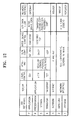
- The A/V system of claim 11, wherein the function-extending module is one of a digital broadcast receiving module, a digital satellite broadcast receiving module, a cable broadcast receiving module, a digital versatile video (DVD) module, a digital video cassette recorder (DVCR) module, a game module, an Internet access module, a hard disc drive module, and a combination of at least two among these modules.
- The A/V system of claim 6, wherein the function-extending module comprises:a communications interface unit for communicating with the base module;a memory unit for storing an IP address and an index page as the control information; anda control unit for providing the IP address and index page to the base module and controlling the function-extending module so that source A/V data in response to a user input received by the base module is sent to the base module through the communications interface unit.
- The A/V system of claim 15, wherein the source A/V data is stored in the memory unit.
- The A/V system of claim 15, wherein the communications interface unit is an IEEE1394 communications interface module.
- The A/V system of claim 15, wherein the function-extending module and the base module adopt a TCP/IP protocol for client-server communications.
- A function-extending module, which is detachably inserted into a module rack so that the function-extending module communicates with a base module capable of reproducing A/V data, the function-extending module capable of sending and receiving the A/V data, storing control information for controlling the function-extending module, and, if inserted into the module rack, providing the control information to the base module and sending source A/V data corresponding to a user input, which is received from the base module, to the base module.
- The function-extending module of claim 19, wherein an index page is stored as the control information in the function-extending module, and the base module has a browser for displaying a main page, in which selection information for the function-extending modules is displayed, requesting an index page to a function-extending module selected through the main page displaying the index page, and sending a user input, which is input through the index page, to the selected function-extending module.
- The function-extending module of claim 20, wherein the function-extending module comprises:a communications interface unit for communicating with the base module;a memory unit for storing an IP address and an index page as the control information; anda control unit for providing the IP address and index page to the base module, and controlling the function-extending module so that source A/V data in response to a user input received from the base module, is sent to the base module through the communications interface unit.
- The function-extending module of claim 21, wherein the source A/V data is stored in the memory unit.
- The function-extending module of claim 21, wherein the communications interface unit is an IEEE1394 interface unit.
- The function-extending module of claim 21, wherein the function-extending module is one of a digital broadcast receiving module, a digital satellite broadcast receiving module, a cable broadcast receiving module, a digital versatile video (DVD) module, a digital video cassette recorder (DVCR) module, a game module, an Internet access module, a hard disc drive module, and a combination of at least two among these modules.
Applications Claiming Priority (4)
| Application Number | Priority Date | Filing Date | Title |
|---|---|---|---|
| KR2000026734 | 2000-05-18 | ||
| KR20000026734 | 2000-05-18 | ||
| KR2001021120 | 2001-04-19 | ||
| KR1020010021120A KR100694043B1 (en) | 2000-05-18 | 2001-04-19 | AB system and its function expansion module |
Publications (2)
| Publication Number | Publication Date |
|---|---|
| EP1156671A2 true EP1156671A2 (en) | 2001-11-21 |
| EP1156671A3 EP1156671A3 (en) | 2004-08-04 |
Family
ID=26638007
Family Applications (1)
| Application Number | Title | Priority Date | Filing Date |
|---|---|---|---|
| EP01304429A Withdrawn EP1156671A3 (en) | 2000-05-18 | 2001-05-18 | Audio/video apparatus |
Country Status (5)
| Country | Link |
|---|---|
| US (1) | US20020008779A1 (en) |
| EP (1) | EP1156671A3 (en) |
| JP (1) | JP2002027348A (en) |
| KR (1) | KR100694043B1 (en) |
| CN (1) | CN1194275C (en) |
Cited By (13)
| Publication number | Priority date | Publication date | Assignee | Title |
|---|---|---|---|---|
| EP1496697A1 (en) * | 2003-07-11 | 2005-01-12 | Archos | Digital system for recording video signals |
| EP1596581A2 (en) | 2004-05-11 | 2005-11-16 | Samsung Electronics Co., Ltd. | A display device with data reading means |
| EP1414238A3 (en) * | 2002-10-24 | 2006-03-29 | Zarlink Semiconductor Limited | Digital television converter |
| DE10145708B4 (en) * | 2000-09-19 | 2007-02-01 | Samsung Electronics Co., Ltd., Suwon | Apparatus and method for connecting a base module to a feature extension module in an AV system |
| US7221410B2 (en) | 2002-12-16 | 2007-05-22 | Samsung Electro-Mechanics Co., Ltd. | Television receiving module and display apparatus and television receiving system using the same |
| DE102006028456A1 (en) * | 2006-04-04 | 2007-10-11 | Grundig Multimedia B.V. | Interface e.g. audio/video link interface, operating method for e.g. digital video broadcasting satellite receiver, involves providing hand shake between electronic devices during start-up and connection of electronic devices |
| EP1628280A4 (en) * | 2003-05-29 | 2008-12-10 | Panasonic Corp | IMAGE DISPLAY DEVICE OF FLAT SCREEN TYPE |
| FR2927440A1 (en) * | 2008-02-07 | 2009-08-14 | Neotion Soc Par Actions Simpli | METHOD FOR ADDITION TO A DIGITAL RECEIVER FLOW DECODING CAPABILITIES THAT MISS IT |
| EP2160014A1 (en) * | 2008-08-27 | 2010-03-03 | Novabase Digital TV Technologies GmbH | Modular digital television decoder |
| EP1936843A3 (en) * | 2006-12-21 | 2012-03-21 | Humax Co., Ltd. | Broadcasting receiver |
| EP2648417A1 (en) * | 2012-04-02 | 2013-10-09 | LG Electronics Inc. | Upgradeable display device and method for controlling the same |
| CN103561294A (en) * | 2013-10-29 | 2014-02-05 | 深圳市数视通科技股份有限公司 | Digital television set top box |
| US9367890B2 (en) | 2011-12-28 | 2016-06-14 | Samsung Electronics Co., Ltd. | Image processing apparatus, upgrade apparatus, display system including the same, and control method thereof |
Families Citing this family (40)
| Publication number | Priority date | Publication date | Assignee | Title |
|---|---|---|---|---|
| CN100521748C (en) * | 2001-04-12 | 2009-07-29 | 索尼公司 | Signal processing device, storage rack and connecting device |
| US20030001981A1 (en) * | 2001-05-21 | 2003-01-02 | Sony Corporation | Modular digital television architecture |
| US20020180890A1 (en) * | 2001-05-21 | 2002-12-05 | Milne James R. | Modular digital television architecture |
| KR100866785B1 (en) * | 2001-08-14 | 2008-11-04 | 삼성전자주식회사 | How to manage module related information in modular system |
| JP4618956B2 (en) * | 2001-12-10 | 2011-01-26 | ソニー株式会社 | Signal processing apparatus, signal processing method, signal processing system, program, and medium |
| JP2003295850A (en) | 2002-04-02 | 2003-10-15 | Pioneer Electronic Corp | Video display device and video data preparing device |
| US20050177662A1 (en) * | 2002-04-04 | 2005-08-11 | Hauke Michael T. | Modular broadcast television products |
| KR20040096406A (en) * | 2003-05-09 | 2004-11-16 | 주식회사 지오나스 | Device for digitally storing broadcasting signal of analog and/or digital type and for performing three-dimensional image |
| RU2319309C2 (en) * | 2003-08-07 | 2008-03-10 | Самсунг Электроникс Ко., Лтд. | Audio/video device, device and method for controlling an audio/video device |
| US20050114780A1 (en) * | 2003-11-12 | 2005-05-26 | Shlomo Turgeman | Adapter card for television reception |
| US20050105007A1 (en) * | 2003-11-14 | 2005-05-19 | Christian John P. | Interchangeable media input cartridge for home entertainment |
| JP2005286914A (en) * | 2004-03-30 | 2005-10-13 | Lg Electronics Inc | Display system, display device and functional module |
| US7644239B2 (en) | 2004-05-03 | 2010-01-05 | Microsoft Corporation | Non-volatile memory cache performance improvement |
| US20060075436A1 (en) * | 2004-09-27 | 2006-04-06 | Schedivy George C | Plug-in television tuner module and method thereof |
| TWI249338B (en) * | 2004-12-22 | 2006-02-11 | Ind Tech Res Inst | Extendable interface and method for digital television |
| CN1310512C (en) * | 2004-12-29 | 2007-04-11 | 国家广播电影电视总局广播科学研究院 | Method of server expansion based on data/video system |
| KR100699259B1 (en) * | 2005-03-08 | 2007-03-27 | 삼성전자주식회사 | Display device |
| CN1851797A (en) * | 2005-04-22 | 2006-10-25 | 鸿富锦精密工业(深圳)有限公司 | Signal adapting device |
| KR100730722B1 (en) * | 2005-07-29 | 2007-06-21 | 삼성전자주식회사 | DM package for receiving digital multimedia broadcasting data, mobile terminal and digital multimedia broadcasting data receiving method |
| KR100799855B1 (en) * | 2005-11-25 | 2008-01-31 | 삼성전기주식회사 | Mobile satellite digital broadcasting receiver |
| US8914557B2 (en) | 2005-12-16 | 2014-12-16 | Microsoft Corporation | Optimizing write and wear performance for a memory |
| US8750785B2 (en) * | 2005-12-28 | 2014-06-10 | The Directv Group, Inc. | Modular receiving unit |
| KR100847855B1 (en) * | 2006-11-07 | 2008-07-23 | 김종부 | Hybrid DM receiver with short range wireless transmission and internet connection |
| JP4529982B2 (en) * | 2007-02-15 | 2010-08-25 | 船井電機株式会社 | Television equipment |
| JP5082562B2 (en) * | 2007-04-17 | 2012-11-28 | 三菱電機株式会社 | Digital broadcast receiving method and apparatus |
| US8320563B2 (en) * | 2007-05-09 | 2012-11-27 | Sony Corporation | Service card adapter |
| SE531020C2 (en) * | 2007-05-30 | 2008-11-18 | Gestamp Hardtech Ab | Bumper beam |
| JP2009055338A (en) * | 2007-08-27 | 2009-03-12 | Funai Electric Co Ltd | Video audio reproducing apparatus |
| US7992184B2 (en) * | 2007-09-18 | 2011-08-02 | Sony Corporation | Hardware module for adding functionality to television using mechanical and wireless links |
| CN101419540B (en) * | 2007-10-26 | 2012-09-26 | 戴尔产品有限公司 | Audio system of information processing system |
| US9032151B2 (en) | 2008-09-15 | 2015-05-12 | Microsoft Technology Licensing, Llc | Method and system for ensuring reliability of cache data and metadata subsequent to a reboot |
| US7953774B2 (en) | 2008-09-19 | 2011-05-31 | Microsoft Corporation | Aggregation of write traffic to a data store |
| CN101489057B (en) * | 2009-01-03 | 2011-02-09 | 海尔集团公司 | Television function expansion component using golden finger connector |
| CN101489059B (en) * | 2009-01-03 | 2011-02-09 | 海尔集团公司 | A TV that can realize function expansion |
| CN101915344B (en) * | 2010-07-13 | 2013-05-22 | 乐克斯瑞(北京)数字技术有限公司 | Assembled digital home terminal with design of independent functional components |
| KR20130078502A (en) * | 2011-12-30 | 2013-07-10 | 삼성전자주식회사 | Display apparatus, upgrading apparatus, display system and control method of the same |
| KR102109051B1 (en) | 2013-08-06 | 2020-05-11 | 삼성전자주식회사 | Function upgrade device, Display apparats and Method for controlling display apparatSs thereof |
| US20160088236A1 (en) * | 2015-12-03 | 2016-03-24 | Randall John Bratton | Audio video content input/output chassis system |
| US20170171593A1 (en) * | 2015-12-14 | 2017-06-15 | Le Holdings (Beijing) Co., Ltd. | Tuner unit module, tuner and electronic device |
| CN109062578B (en) * | 2018-07-31 | 2022-03-01 | 成都华栖云科技有限公司 | Development platform based on APP modularization |
Family Cites Families (46)
| Publication number | Priority date | Publication date | Assignee | Title |
|---|---|---|---|---|
| FR2449379A1 (en) * | 1979-02-15 | 1980-09-12 | Scart | AUDIO-VIDEO DYNAMIC INTERCONNECTION SYSTEM |
| JP3506439B2 (en) * | 1991-05-31 | 2004-03-15 | 松下電器産業株式会社 | Television receiver |
| JPH06169440A (en) * | 1992-11-30 | 1994-06-14 | Hitachi Ltd | Television receiver |
| JPH06319094A (en) * | 1993-04-16 | 1994-11-15 | Matsushita Electric Ind Co Ltd | Television equipment and its remote control device |
| CN1113302C (en) * | 1993-07-30 | 2003-07-02 | 佳能株式会社 | Controller and method for controlling device through communication line |
| JP3228381B2 (en) * | 1993-10-29 | 2001-11-12 | ソニー株式会社 | AV selector |
| US5591984A (en) * | 1995-06-15 | 1997-01-07 | The Whitaker Corporation | Current sensing daisy-chain bypass arrangement |
| US6359636B1 (en) * | 1995-07-17 | 2002-03-19 | Gateway, Inc. | Graphical user interface for control of a home entertainment system |
| US5787259A (en) * | 1996-03-29 | 1998-07-28 | Microsoft Corporation | Digital interconnects of a PC with consumer electronics devices |
| JP2000511723A (en) * | 1996-06-04 | 2000-09-05 | テレフオンアクチーボラゲツト エル エム エリクソン(パブル) | Modem with IP support |
| US5793366A (en) * | 1996-11-12 | 1998-08-11 | Sony Corporation | Graphical display of an animated data stream between devices on a bus |
| EP0821505A1 (en) * | 1996-07-25 | 1998-01-28 | Hewlett-Packard Company | Apparatus providing connectivity between devices attached to different interfaces of the apparatus |
| GB9617264D0 (en) * | 1996-08-16 | 1996-09-25 | Thwaite Paul | Improvements relating to means of controlling different apparatus |
| US5956487A (en) * | 1996-10-25 | 1999-09-21 | Hewlett-Packard Company | Embedding web access mechanism in an appliance for user interface functions including a web server and web browser |
| JP3528480B2 (en) * | 1996-11-19 | 2004-05-17 | ソニー株式会社 | EPG device and control method thereof |
| US6469633B1 (en) * | 1997-01-06 | 2002-10-22 | Openglobe Inc. | Remote control of electronic devices |
| JP3870983B2 (en) * | 1997-02-17 | 2007-01-24 | ソニー株式会社 | Electronic device control apparatus and method, and electronic device |
| JP4038700B2 (en) * | 1997-02-17 | 2008-01-30 | ソニー株式会社 | Electronic device control apparatus and method, and information processing system and method |
| US6134615A (en) * | 1997-05-13 | 2000-10-17 | Micron Electronics, Inc. | System for facilitating the replacement or insertion of devices in a computer system through the use of a graphical user interface |
| US6191822B1 (en) * | 1997-06-20 | 2001-02-20 | Sony Corporation | Method of and apparatus for separating audio and video data from a combined audio/video stream of data |
| DE69838439T2 (en) * | 1997-06-25 | 2008-06-12 | Samsung Electronics Co., Ltd., Suwon | Method and device for monitoring devices in a home network |
| US7103834B1 (en) * | 1997-06-25 | 2006-09-05 | Samsung Electronics Co., Ltd. | Method and apparatus for a home network auto-tree builder |
| WO1999007114A1 (en) * | 1997-08-04 | 1999-02-11 | Matsushita Electric Industrial Co., Ltd. | A network control system |
| JP5036098B2 (en) * | 1997-09-18 | 2012-09-26 | トムソン コンシユーマ エレクトロニクス インコーポレイテツド | Digital television apparatus for controlling peripheral electronic devices via a digital bus |
| US6438693B1 (en) * | 1997-09-30 | 2002-08-20 | Sony Corporation | Modular broadcast receiver system and memo |
| US6886055B2 (en) * | 1997-12-15 | 2005-04-26 | Clearcube Technology, Inc. | Computer on a card with a remote human interface |
| US6052750A (en) * | 1998-01-06 | 2000-04-18 | Sony Corporation Of Japan | Home audio/video network for generating default control parameters for devices coupled to the network, and replacing updated control parameters therewith |
| US6038625A (en) * | 1998-01-06 | 2000-03-14 | Sony Corporation Of Japan | Method and system for providing a device identification mechanism within a consumer audio/video network |
| US6292172B1 (en) * | 1998-03-20 | 2001-09-18 | Samir B. Makhlouf | System and method for controlling and integrating various media devices in a universally controlled system |
| US6160797A (en) * | 1998-04-03 | 2000-12-12 | Starguide Digital Networks, Inc. | Satellite receiver/router, system, and method of use |
| CN1269116A (en) * | 1998-05-13 | 2000-10-04 | 松下电器产业株式会社 | Network cotnrol system, controller, and device |
| US6373507B1 (en) * | 1998-09-14 | 2002-04-16 | Microsoft Corporation | Computer-implemented image acquistion system |
| US6219042B1 (en) * | 1998-09-15 | 2001-04-17 | Webtv Networks, Inc. | Selective reestablishment of internet connectivity based on duration of user inactivity |
| US6169725B1 (en) * | 1998-10-30 | 2001-01-02 | Sony Corporation Of Japan | Apparatus and method for restoration of internal connections in a home audio/video system |
| BR0004006A (en) * | 1999-01-06 | 2002-01-29 | Robert G Harrison | Applications with multiple modes of operation |
| US6363434B1 (en) * | 1999-03-30 | 2002-03-26 | Sony Corporation Of Japan | Method of managing resources within a network of consumer electronic devices |
| US6542882B1 (en) * | 1999-04-22 | 2003-04-01 | Gateway, Inc. | System and method for providing a database of content having like associations |
| US6910068B2 (en) * | 1999-06-11 | 2005-06-21 | Microsoft Corporation | XML-based template language for devices and services |
| US6900847B1 (en) * | 1999-07-30 | 2005-05-31 | Chyron Corporation | Video hardware and software system |
| US6526581B1 (en) * | 1999-08-03 | 2003-02-25 | Ucentric Holdings, Llc | Multi-service in-home network with an open interface |
| JP3318289B2 (en) * | 1999-08-10 | 2002-08-26 | 松下電送システム株式会社 | Home network gateway equipment |
| US6813651B1 (en) * | 2000-02-18 | 2004-11-02 | Controlnet, Inc. | Interface device for ethernet transceiver and 1394 controller |
| US6580950B1 (en) * | 2000-04-28 | 2003-06-17 | Echelon Corporation | Internet based home communications system |
| KR100467574B1 (en) * | 2000-09-19 | 2005-01-24 | 삼성전자주식회사 | Apparatus and method for connecting base module and function-extending module in AV system |
| US6792319B1 (en) * | 2000-10-19 | 2004-09-14 | Destiny Networks, Inc. | Home automation system and method |
| US6792323B2 (en) * | 2002-06-27 | 2004-09-14 | Openpeak Inc. | Method, system, and computer program product for managing controlled residential or non-residential environments |
-
2001
- 2001-04-19 KR KR1020010021120A patent/KR100694043B1/en not_active Expired - Fee Related
- 2001-05-15 US US09/854,916 patent/US20020008779A1/en not_active Abandoned
- 2001-05-16 JP JP2001146779A patent/JP2002027348A/en active Pending
- 2001-05-18 EP EP01304429A patent/EP1156671A3/en not_active Withdrawn
- 2001-05-18 CN CNB011220708A patent/CN1194275C/en not_active Expired - Fee Related
Cited By (27)
| Publication number | Priority date | Publication date | Assignee | Title |
|---|---|---|---|---|
| DE10145708B4 (en) * | 2000-09-19 | 2007-02-01 | Samsung Electronics Co., Ltd., Suwon | Apparatus and method for connecting a base module to a feature extension module in an AV system |
| US7611382B2 (en) | 2002-10-24 | 2009-11-03 | Intel Corporation | Digital television tuner with digital to analog converter embedded in a connector |
| EP1414238A3 (en) * | 2002-10-24 | 2006-03-29 | Zarlink Semiconductor Limited | Digital television converter |
| US7221410B2 (en) | 2002-12-16 | 2007-05-22 | Samsung Electro-Mechanics Co., Ltd. | Television receiving module and display apparatus and television receiving system using the same |
| EP1628280A4 (en) * | 2003-05-29 | 2008-12-10 | Panasonic Corp | IMAGE DISPLAY DEVICE OF FLAT SCREEN TYPE |
| FR2857547A1 (en) * | 2003-07-11 | 2005-01-14 | Archos | DIGITAL SYSTEM FOR RECORDING VIDEO SIGNALS. |
| EP1496697A1 (en) * | 2003-07-11 | 2005-01-12 | Archos | Digital system for recording video signals |
| EP1596581A2 (en) | 2004-05-11 | 2005-11-16 | Samsung Electronics Co., Ltd. | A display device with data reading means |
| EP1596581A3 (en) * | 2004-05-11 | 2008-10-22 | Samsung Electronics Co., Ltd. | A display device with data reading means |
| US8396354B2 (en) | 2004-05-11 | 2013-03-12 | Samsung Electronics Co., Ltd. | Display apparatus, method, and computer system |
| DE102006028456A1 (en) * | 2006-04-04 | 2007-10-11 | Grundig Multimedia B.V. | Interface e.g. audio/video link interface, operating method for e.g. digital video broadcasting satellite receiver, involves providing hand shake between electronic devices during start-up and connection of electronic devices |
| EP1936843A3 (en) * | 2006-12-21 | 2012-03-21 | Humax Co., Ltd. | Broadcasting receiver |
| WO2009103916A1 (en) * | 2008-02-07 | 2009-08-27 | Neotion (Sa) | Method for selecting channels in a television set including extension modules for receiving supplementary formats |
| FR2927440A1 (en) * | 2008-02-07 | 2009-08-14 | Neotion Soc Par Actions Simpli | METHOD FOR ADDITION TO A DIGITAL RECEIVER FLOW DECODING CAPABILITIES THAT MISS IT |
| AU2009287020B2 (en) * | 2008-08-27 | 2013-08-15 | Novabase Digital Tv Technologies Gmbh | Modular digital television decoder |
| EP2383977A1 (en) * | 2008-08-27 | 2011-11-02 | Novabase Digital TV Technologies GmbH | Modular digital television decoder |
| CN102177704A (en) * | 2008-08-27 | 2011-09-07 | 诺瓦数位电视科技股份有限公司 | Modular Digital TV Decoder |
| RU2464724C1 (en) * | 2008-08-27 | 2012-10-20 | Новабейз Диджитал Тв Текнолоджиз Гмбх | Modular receiver of digital multimedia information |
| WO2010022935A1 (en) * | 2008-08-27 | 2010-03-04 | Novabase Digital Tv Technologies Gmbh | Modular digital television decoder |
| EP2160014A1 (en) * | 2008-08-27 | 2010-03-03 | Novabase Digital TV Technologies GmbH | Modular digital television decoder |
| US9307286B2 (en) | 2008-08-27 | 2016-04-05 | Volker Franke | Modular digital television decoder |
| US9367890B2 (en) | 2011-12-28 | 2016-06-14 | Samsung Electronics Co., Ltd. | Image processing apparatus, upgrade apparatus, display system including the same, and control method thereof |
| US9396511B2 (en) | 2011-12-28 | 2016-07-19 | Samsung Electronics Co., Ltd. | Image processing apparatus, upgrade apparatus, display system including the same, and control method thereof |
| EP2648417A1 (en) * | 2012-04-02 | 2013-10-09 | LG Electronics Inc. | Upgradeable display device and method for controlling the same |
| US9007526B2 (en) | 2012-04-02 | 2015-04-14 | Lg Electronics Inc. | Upgradeable display device and method for controlling the same |
| CN103561294A (en) * | 2013-10-29 | 2014-02-05 | 深圳市数视通科技股份有限公司 | Digital television set top box |
| CN103561294B (en) * | 2013-10-29 | 2017-01-11 | 深圳市数视通科技股份有限公司 | Digital television set top box |
Also Published As
| Publication number | Publication date |
|---|---|
| JP2002027348A (en) | 2002-01-25 |
| KR100694043B1 (en) | 2007-03-12 |
| CN1337640A (en) | 2002-02-27 |
| KR20010106185A (en) | 2001-11-29 |
| EP1156671A3 (en) | 2004-08-04 |
| US20020008779A1 (en) | 2002-01-24 |
| CN1194275C (en) | 2005-03-23 |
Similar Documents
| Publication | Publication Date | Title |
|---|---|---|
| EP1156671A2 (en) | Audio/video apparatus | |
| US9153125B2 (en) | Programmable multimedia controller with programmable services | |
| US8378791B2 (en) | Image reproduction system and signal processor used for the same | |
| CA2748888C (en) | Tv function expansion component using gold finger connector | |
| US20090249420A1 (en) | Method for configuring video apparatus according to video system and content, and video apparatus and server applying the same | |
| CA2748140C (en) | Signal source and tv with the signal source | |
| US20040247280A1 (en) | Recording and reproducing apparatus, recording and reproducing method, and AV system | |
| US20050034154A1 (en) | User interface for a video display device | |
| US6912613B2 (en) | Apparatus and method for connecting base module and function-extending module in AV system | |
| US6664459B2 (en) | Music file recording/reproducing module | |
| EP2352283B1 (en) | Image signal processing apparatus and control method thereof | |
| US20110131616A1 (en) | Terminal device, media processing apparatus connected to terminal device, and controlling method thereof | |
| US20020019986A1 (en) | Enhanced home entertainment system with removable long-term storage | |
| EP2187382A2 (en) | Video apparatus and method of controlling the video apparatus | |
| KR100467574B1 (en) | Apparatus and method for connecting base module and function-extending module in AV system | |
| KR100425295B1 (en) | music file recording/reproducing module for AV system | |
| KR100589778B1 (en) | Method and device for playing external data of digital TV | |
| JPH11110330A (en) | AV / PC system | |
| WO2010122573A2 (en) | Integrated dvd-dth system | |
| KR20020082021A (en) | Function-extending module for AV system | |
| KR20060005922A (en) | Video player | |
| JP2010011295A (en) | Electronic device | |
| KR20050056515A (en) | Compound a/v system capable of upgradding a driving program and a method thereof | |
| KR20070072082A (en) | Television system | |
| KR20060056501A (en) | Ave system and its control method |
Legal Events
| Date | Code | Title | Description |
|---|---|---|---|
| PUAI | Public reference made under article 153(3) epc to a published international application that has entered the european phase |
Free format text: ORIGINAL CODE: 0009012 |
|
| AK | Designated contracting states |
Kind code of ref document: A2 Designated state(s): AT BE CH CY DE DK ES FI FR GB GR IE IT LI LU MC NL PT SE TR |
|
| AX | Request for extension of the european patent |
Free format text: AL;LT;LV;MK;RO;SI |
|
| PUAL | Search report despatched |
Free format text: ORIGINAL CODE: 0009013 |
|
| AK | Designated contracting states |
Kind code of ref document: A3 Designated state(s): AT BE CH CY DE DK ES FI FR GB GR IE IT LI LU MC NL PT SE TR |
|
| AX | Request for extension of the european patent |
Extension state: AL LT LV MK RO SI |
|
| RIC1 | Information provided on ipc code assigned before grant |
Ipc: 7H 04N 7/24 B Ipc: 7H 04N 5/445 B Ipc: 7H 04N 5/44 B Ipc: 7H 04N 5/775 B Ipc: 7H 04N 5/00 A |
|
| RAP1 | Party data changed (applicant data changed or rights of an application transferred) |
Owner name: SAMSUNG ELECTRONICS CO., LTD. |
|
| 17P | Request for examination filed |
Effective date: 20041221 |
|
| AKX | Designation fees paid |
Designated state(s): DE GB NL |
|
| 17Q | First examination report despatched |
Effective date: 20071213 |
|
| STAA | Information on the status of an ep patent application or granted ep patent |
Free format text: STATUS: THE APPLICATION IS DEEMED TO BE WITHDRAWN |
|
| 18D | Application deemed to be withdrawn |
Effective date: 20100629 |