EP1156578A1 - Moteur pas-à-pas en forme de disque - Google Patents
Moteur pas-à-pas en forme de disque Download PDFInfo
- Publication number
- EP1156578A1 EP1156578A1 EP01110561A EP01110561A EP1156578A1 EP 1156578 A1 EP1156578 A1 EP 1156578A1 EP 01110561 A EP01110561 A EP 01110561A EP 01110561 A EP01110561 A EP 01110561A EP 1156578 A1 EP1156578 A1 EP 1156578A1
- Authority
- EP
- European Patent Office
- Prior art keywords
- stator
- rotor
- bearing
- motor according
- motor
- Prior art date
- Legal status (The legal status is an assumption and is not a legal conclusion. Google has not performed a legal analysis and makes no representation as to the accuracy of the status listed.)
- Granted
Links
Images


Classifications
-
- H—ELECTRICITY
- H02—GENERATION; CONVERSION OR DISTRIBUTION OF ELECTRIC POWER
- H02K—DYNAMO-ELECTRIC MACHINES
- H02K7/00—Arrangements for handling mechanical energy structurally associated with dynamo-electric machines, e.g. structural association with mechanical driving motors or auxiliary dynamo-electric machines
- H02K7/14—Structural association with mechanical loads, e.g. with hand-held machine tools or fans
-
- H—ELECTRICITY
- H02—GENERATION; CONVERSION OR DISTRIBUTION OF ELECTRIC POWER
- H02K—DYNAMO-ELECTRIC MACHINES
- H02K21/00—Synchronous motors having permanent magnets; Synchronous generators having permanent magnets
- H02K21/12—Synchronous motors having permanent magnets; Synchronous generators having permanent magnets with stationary armatures and rotating magnets
- H02K21/24—Synchronous motors having permanent magnets; Synchronous generators having permanent magnets with stationary armatures and rotating magnets with magnets axially facing the armatures, e.g. hub-type cycle dynamos
-
- H—ELECTRICITY
- H02—GENERATION; CONVERSION OR DISTRIBUTION OF ELECTRIC POWER
- H02K—DYNAMO-ELECTRIC MACHINES
- H02K37/00—Motors with rotor rotating step by step and without interrupter or commutator driven by the rotor, e.g. stepping motors
- H02K37/10—Motors with rotor rotating step by step and without interrupter or commutator driven by the rotor, e.g. stepping motors of permanent magnet type
- H02K37/12—Motors with rotor rotating step by step and without interrupter or commutator driven by the rotor, e.g. stepping motors of permanent magnet type with stationary armatures and rotating magnets
- H02K37/125—Magnet axially facing armature
-
- H—ELECTRICITY
- H02—GENERATION; CONVERSION OR DISTRIBUTION OF ELECTRIC POWER
- H02K—DYNAMO-ELECTRIC MACHINES
- H02K5/00—Casings; Enclosures; Supports
- H02K5/04—Casings or enclosures characterised by the shape, form or construction thereof
- H02K5/16—Means for supporting bearings, e.g. insulating supports or means for fitting bearings in the bearing-shields
- H02K5/173—Means for supporting bearings, e.g. insulating supports or means for fitting bearings in the bearing-shields using bearings with rolling contact, e.g. ball bearings
- H02K5/1737—Means for supporting bearings, e.g. insulating supports or means for fitting bearings in the bearing-shields using bearings with rolling contact, e.g. ball bearings radially supporting the rotor around a fixed spindle; radially supporting the rotor directly
-
- H—ELECTRICITY
- H02—GENERATION; CONVERSION OR DISTRIBUTION OF ELECTRIC POWER
- H02K—DYNAMO-ELECTRIC MACHINES
- H02K5/00—Casings; Enclosures; Supports
- H02K5/26—Means for adjusting casings relative to their supports
-
- H—ELECTRICITY
- H02—GENERATION; CONVERSION OR DISTRIBUTION OF ELECTRIC POWER
- H02K—DYNAMO-ELECTRIC MACHINES
- H02K7/00—Arrangements for handling mechanical energy structurally associated with dynamo-electric machines, e.g. structural association with mechanical driving motors or auxiliary dynamo-electric machines
- H02K7/08—Structural association with bearings
- H02K7/086—Structural association with bearings radially supporting the rotor around a fixed spindle; radially supporting the rotor directly
Definitions
- the present invention relates to a stepping motor, and in particular a motor step by step having a multipole magnet in the form of a disc.
- the motor according to this patent comprises a rotor having a thrust motor axis and a multipolar magnet in the form of a disc fixed on the axis by pieces of intermediate fixing.
- the rotor is mounted in a stator and supported by two bearings, one on each side of the disc magnet, in the form of bearings with marbles.
- This motor has two phases and has two coils surrounding magnetic circuit elements in each half of the stator.
- the circuits magnetic have air gaps in which the rotor magnet is positioned.
- the member for driving the object to be moved is attached to the motor shaft outside the housing.
- the size of such an assembly in relation to the torque supplied and the number of step by step are not satisfactory.
- An object of the invention is to provide a compact, precise and precise stepping motor. having good performance. For certain applications, it is advantageous to have a short motor in the direction of the axis of rotation. It is also advantageous to reduce the manufacturing cost of stepping motors.
- Objects of the invention are achieved by a stepping motor according to the claim 1.
- a stepping motor comprises a stator comprising at least two magnetic circuits, and a rotor mounted in rotation on a stator by a bearing, the rotor comprising a member provided with magnets or a multipolar magnet essentially in the form of a disc mounted on a part rotor part, said rotor part being fixed to a radially outer part of the magnet, and a radially inner part of the magnet being disposed in the air gap of said magnetic circuits.
- the rotor part may have a central opening through which extends part of the stator.
- the construction according to the invention makes it possible to produce a particularly compact stepper motor.
- the rotor part can be in the form of an essentially flat ring.
- the rotor part may further include teeth arranged on its periphery to engage teeth or complementary holes of an object or organ to move.
- the rotor part and / or the magnet can be fixed on a movable ring of the bearing, preferably the outer ring of the bearing, the bearing being preferably a ball bearing.
- the ball bearing can be a bearing supporting axial and radial forces.
- the inner crown of the bearing can be mounted on a cylindrical surface of part of the stator. In order to reduce the length of the motor in the direction along its axis of rotation, the inner bearing crown may be shorter than the inner crown outside of the bearing against which the rotor part is fixed.
- the construction according to the invention makes it possible to produce an engine with a single bearing, in particular a ball bearing with four contact points having a large diameter, thus allowing to have an extremely compact but nevertheless very rigid.
- the engine is made of a small number of pieces, so that its manufacture is economical.
- the stator may include a first part of the stator on which are mounted coils and a second stator part in the form of yokes mounted against this first part to close the magnetic circuits comprising an air gap between radially outer parts of the first part of stator and cylinder heads, respectively.
- Each magnetic circuit can therefore include a coil and a cylinder head.
- two coils and two cylinder heads are arranged symmetrically on either side of a line of symmetry passing through the center motor rotation.
- the radially outer parts of the cylinder heads and the first part of stator can be provided with teeth or other forms of extension opposite one another to form pairs of poles stator which attracts pairs of reverse poles from the magnet when the coil of the corresponding magnetic circuit is supplied with electric current.
- the pairs of poles of the magnet face pairs of poles stator and then the other coil is powered to attract pairs magnet poles, and so on, to move the rotor forward.
- Teeth or extensions of each cylinder head part are arranged symmetrically by relative to the line of symmetry, but are not diametrically symmetrical since the teeth are moved angularly, like for stepper motors conventional, so that the poles of the magnet opposite extensions or teeth of one of the magnetic circuits are not opposite the teeth or extensions of the other magnetic circuit.
- the motor according to the invention can have more than two phases without departing from the scope of the invention.
- the engine may have multiple magnetic circuits occupying sectors of the form generally cylindrical of the motor, the sector having an angle essentially of 120 ° for a three-phase motor and 90 ° for a four-phase motor.
- the first part of the stator on which the coils are mounted can be a sintered material having good magnetic permeability but poor electrical conductivity, so as to limit the eddy current losses in a compact and inexpensive construction.
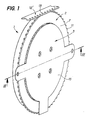
- a stepping motor 1 has a rotor 2, a stator 3 and a bearing 4 for the rotational mounting of the rotor 2 to stator 3.
- the rotor 2 comprises a permanent multipolar magnet 5 in the form a ring or a disc having a central opening 6.
- the rotor has furthermore a rotor part 7 in the form of a ring or disc having a central opening 8, this part being fixed to the magnet 5, and more particularly against a radially outer part 9 of the magnet.
- a radially inner part 10 of the magnet extending between the central opening 6 of the magnet and the central opening 8 of the part 7 of the rotor, is provided with a plurality of pairs of magnetic poles arranged around the magnet, by example in the form of ring segments where the pairs of adjacent poles have opposite magnetic fields.
- the rotor is further provided with teeth 11 on its periphery to engage and train an organ or object to be moved 12 ' which is, in the example shown, a strip having perforations 13. This construction therefore makes it possible to translate the rotation of the rotor directly into a translational movement of a band or other drive member 12 '.
- the rotor 2 in one piece, the permanent magnet and the outer rotor part being in one piece of magnetic material permed.
- the stator 3 comprises a first part of the stator 12, a second part of stator 13, coils 14, 14 'and a flange 15.
- the first stator part 12 comprises, around its periphery, a plurality of teeth or protrusions 16 extending in the axial direction A (the direction the axis of rotation of the motor) and the core parts 17, 17 ', around which are mounted the electric coils 14, 14 'respectively.
- the protrusions 16 and the core parts 17, 17 ′ are joined together by a disc base 18.
- the second stator part 13 has two yokes 19, 19 ', one for each coil and therefore for each phase of the engine, the cylinder heads being fixed against the free surfaces 20 of the core parts 17, 17 ', the surfaces being essentially orthogonal to axis A.
- the cylinder heads 19, 19 ' are provided with protrusions or extensions 21 around their edges so as to be arranged opposite the protrusions 16 of the first part of the stator when the parts are assembled.
- the space between the protrusions or extensions 21, 16 of the second and first parts of the stator constitute the air gaps of the respective magnetic circuits each formed by one of the yokes, one of the core parts 17, 17 'and the base 18.
- the yokes 19, 19 ′ are separated by a slot 22.
- the first stator part 12 and / or the second stator part 13 can be of a sintered material having good magnetic permeability but a low electrical conductivity, so as to reduce losses by Foucault. This avoids construction of the magnetic circuit by sheets, in particular to reduce the manufacturing cost while allowing obtain three-dimensional shapes, for example teeth and nucleus, compact and rigid.
- the cylinder heads 19 are in the form of a disc relatively thin compared to the first stator part, and can also be made of sintered material or simply a plate of material (non-sintered) having good magnetic permeability.
- the flange 15 can be mounted against the second stator part 13 and have holes 23 aligned with holes 24, 25 of the second and first stator parts, the holes 25 of the first part being for example threaded for the assembly of these components.
- the flange can be fitted with various elements, such as fixing lugs 26, so that mount the motor on a support.
- the stator has a passage 27 passing through the outer ring 30 of the base 18 for housing a connector and / or a small electronic card connecting the conductors of the coils to an external electronic or electrical circuit.
- the two cylinder heads 19 are arranged symmetrically on the side and on the other side of a line of symmetry passing through the center of rotation of the motor, but that the extensions or protuberances are angularly displaced by so that the teeth of one cylinder head relative to the other are not diametrically opposite.
- This angular displacement is a characteristic known stepping motors and will therefore not be described in more detail.
- the angular spacing between the teeth is 2 ⁇ / 64 radians, in this case particular, which corresponds to 256 steps / revolution, since there are four steps per pair stator poles for a two-phase motor.
- the motor has a rotor having an outside diameter of 81.5 mm and has 64 teeth, so there is a 4mm spacing between the teeth.
- the motor moves the strip 12 'with a force of around 15 Newton in 20 msec with an accuracy of the order of 15 microns.
- the length L of the motor is approximately 10 mm.
- the choice of 64 pairs of stator poles optimizes the tangential force (force on the strip 12 ') as illustrated on the force curve with respect to the number of pairs of poles in Fig. 5.
- the relatively large diameter of the magnet especially in because of its arrangement around the coils, allows a very compact construction but providing high torque, as can be note with reference to FIG. 4 where the tangential force (force on the strip 12 ') is proportional to the outside radius of the magnet.
- the bearing 4 is, in this embodiment, a four-ball bearing contact points supporting radial and axial force components.
- the stiffness inherent in such a bearing is improved by increasing its diameter.
- the present invention takes advantage of this characteristic, in that it has the bearing 4 around the stator 3.
- This construction makes it possible inter alia to provide the motor with only one bearing and therefore having a very small length L in the axial direction A, while having great rigidity and precision.
- the crown inner 27 is mounted on the outer cylindrical surface 28 of the first stator part 12, and the outer ring 29 of the bearing 4 is fixed against the rotor part 7.
- the inner ring 27 has a shorter length than the outer ring 29, in the axial direction A, to allow to have the radially outer part 9 of the magnet against a radially part rotor part 7.
Landscapes
- Engineering & Computer Science (AREA)
- Power Engineering (AREA)
- Motor Or Generator Frames (AREA)
- Permanent Magnet Type Synchronous Machine (AREA)
- Linear Motors (AREA)
- Iron Core Of Rotating Electric Machines (AREA)
- Moving Of Heads (AREA)
- Reciprocating, Oscillating Or Vibrating Motors (AREA)
Abstract
Description
Claims (11)
- Moteur pas-à-pas comportant un stator comprenant au moins deux circuits magnétiques et un rotor monté en rotation sur le stator par un palier, le rotor comprenant un organe muni d'aimants ou d'un aimant multipolaire, essentiellement sous forme de disque ayant une ouverture centrale, monté sur une partie de rotor, caractérisé en ce que ladite partie de rotor est fixée à une partie radialement extérieure de l'aimant ou de l'organe muni d'aimants, une partie radialement intérieure de l'aimant ou de l'organe muni d'aimants étant disposée dans l'entrefer desdits circuits magnétiques.
- Moteur selon la revendication 1, caractérisé en ce que ladite partie de rotor (7) est munie d'une ouverture centrale (8) à travers laquelle s'étend une partie de stator (3).
- Moteur selon l'une des revendications précédentes, caractérisé en ce que ladite partie de rotor a une forme essentiellement plate et comprend des dents (11) agencées sur son pourtour.
- Moteur selon l'une des revendications précédentes, caractérisé en ce que le rotor est fixé à une couronne radialement extérieure (29) du palier, alors que le stator est fixé à une couronne radialement intérieure (27) du palier.
- Moteur selon l'une des revendications précédentes, caractérisé en ce que le palier comporte un roulement à billes à quatre points de contact.
- Moteur selon l'une des deux revendications précédentes, caractérisé en ce que la couronne radialement intérieure du palier est plus courte que la couronne radialement extérieure du palier selon la direction (A) de l'axe de rotation du moteur.
- Moteur selon l'une des revendications précédentes, caractérisé en ce que le stator comporte une première partie de stator (12) comprenant des parties de noyau (17, 17'), une pour chaque bobine électrique (14, 14') du circuit magnétique, une base (18) et une pluralité de protubérances ou extensions (16).
- Moteur selon la revendication précédente, caractérisé en ce qu'il comprend en outre une deuxième partie de stator (13) sous forme de culasses (19, 19'), une pour chaque phase de moteur, et étant fixé contre la première partie de stator de façon à former un circuit magnétique pour chaque phase de moteur.
- Moteur selon l'une des deux revendications précédentes, caractérisé en ce que la première partie de stator est faite d'une seule pièce en matière frittée ayant une bonne perméabilité magnétique.
- Moteur selon l'une des trois revendications précédentes, caractérisé en ce que la deuxième partie de stator (13) a une forme essentiellement plate et comporte des protubérances ou extensions radiales (21) sur le pourtour disposées en regard des extensions ou protubérances de la première partie du stator pour former des paires de pôles statoriques.
- Moteur selon l'une des revendications précédentes, caractérisé en ce qu'il ne comporte qu'un palier.
Applications Claiming Priority (2)
| Application Number | Priority Date | Filing Date | Title |
|---|---|---|---|
| CH10122000 | 2000-05-19 | ||
| CH10122000 | 2000-05-19 |
Publications (2)
| Publication Number | Publication Date |
|---|---|
| EP1156578A1 true EP1156578A1 (fr) | 2001-11-21 |
| EP1156578B1 EP1156578B1 (fr) | 2010-04-07 |
Family
ID=4552519
Family Applications (1)
| Application Number | Title | Priority Date | Filing Date |
|---|---|---|---|
| EP01110561A Expired - Lifetime EP1156578B1 (fr) | 2000-05-19 | 2001-04-30 | Moteur pas-à-pas en forme de disque |
Country Status (4)
| Country | Link |
|---|---|
| US (1) | US6509663B2 (fr) |
| EP (1) | EP1156578B1 (fr) |
| AT (1) | ATE463877T1 (fr) |
| DE (1) | DE60141730D1 (fr) |
Cited By (1)
| Publication number | Priority date | Publication date | Assignee | Title |
|---|---|---|---|---|
| CH699399A1 (fr) * | 2008-08-22 | 2010-02-26 | Precistep Sa | Moteur bague électrique. |
Families Citing this family (7)
| Publication number | Priority date | Publication date | Assignee | Title |
|---|---|---|---|---|
| US6822369B2 (en) * | 2001-07-27 | 2004-11-23 | Ta-Ching Pong | Pulse propelling flat induction motor |
| WO2005019642A1 (fr) * | 2003-08-21 | 2005-03-03 | General Electric Company | Changement de pas des pales d'une eolienne a l'aide d'un moteur pas a pas electrique |
| DE102004021537A1 (de) * | 2004-05-03 | 2005-12-08 | Robert Bosch Gmbh | Elektromotor und Getriebe-Antriebseinheit für Stellantriebe im Kraftfahrzeug |
| JP2006230184A (ja) * | 2005-01-18 | 2006-08-31 | Daikin Ind Ltd | 電機子、モータ及び圧縮機並びにそれらの製造方法 |
| DE102009017028B4 (de) | 2009-04-14 | 2014-08-21 | Siemens Aktiengesellschaft | Windenergieanlage und Antriebseinrichtung zur Verstellung eines Rotorblatts |
| EP2623775B1 (fr) * | 2010-09-20 | 2015-06-03 | ALSTOM Renewable Technologies | Rotor d'éolienne avec frein pour la régulation de pas |
| DE102012207758A1 (de) * | 2012-05-09 | 2013-11-14 | Aktiebolaget Skf | Vorrichtung mit wenigstens einem Scheibenläufermotorrotor und Montageverfahren |
Citations (6)
| Publication number | Priority date | Publication date | Assignee | Title |
|---|---|---|---|---|
| US4330727A (en) * | 1979-12-27 | 1982-05-18 | Claude Oudet | Electric step motor |
| US4714853A (en) * | 1986-09-04 | 1987-12-22 | Tri-Tech, Inc. | Low profile electric motor |
| US4922145A (en) * | 1988-11-17 | 1990-05-01 | Eastman Kodak Company | Stepper motor |
| JPH05252713A (ja) * | 1991-10-28 | 1993-09-28 | Sony Corp | ブラシレスモータ |
| JPH07244922A (ja) * | 1994-03-01 | 1995-09-19 | Matsushita Electric Ind Co Ltd | ブラシレスモータ |
| US5844338A (en) * | 1995-12-18 | 1998-12-01 | Siemens Electric Limited | Slim-line brushless motor with inside mounted single bearing |
Family Cites Families (3)
| Publication number | Priority date | Publication date | Assignee | Title |
|---|---|---|---|---|
| US3803431A (en) * | 1971-11-24 | 1974-04-09 | Fujitsu Ltd | Electric pulse motor |
| US4198582A (en) * | 1977-06-24 | 1980-04-15 | Exxon Research & Engineering Co. | High performance stepper motor |
| DE4121428A1 (de) * | 1991-06-28 | 1993-01-07 | Papst Motoren Gmbh & Co Kg | Spindelmotor, insbesondere fuer plattenspeicher |
-
2001
- 2001-04-30 AT AT01110561T patent/ATE463877T1/de not_active IP Right Cessation
- 2001-04-30 EP EP01110561A patent/EP1156578B1/fr not_active Expired - Lifetime
- 2001-04-30 DE DE60141730T patent/DE60141730D1/de not_active Expired - Lifetime
- 2001-05-02 US US09/847,714 patent/US6509663B2/en not_active Expired - Lifetime
Patent Citations (6)
| Publication number | Priority date | Publication date | Assignee | Title |
|---|---|---|---|---|
| US4330727A (en) * | 1979-12-27 | 1982-05-18 | Claude Oudet | Electric step motor |
| US4714853A (en) * | 1986-09-04 | 1987-12-22 | Tri-Tech, Inc. | Low profile electric motor |
| US4922145A (en) * | 1988-11-17 | 1990-05-01 | Eastman Kodak Company | Stepper motor |
| JPH05252713A (ja) * | 1991-10-28 | 1993-09-28 | Sony Corp | ブラシレスモータ |
| JPH07244922A (ja) * | 1994-03-01 | 1995-09-19 | Matsushita Electric Ind Co Ltd | ブラシレスモータ |
| US5844338A (en) * | 1995-12-18 | 1998-12-01 | Siemens Electric Limited | Slim-line brushless motor with inside mounted single bearing |
Non-Patent Citations (2)
| Title |
|---|
| PATENT ABSTRACTS OF JAPAN vol. 18, no. 17 (E - 1488) 12 January 1994 (1994-01-12) * |
| PATENT ABSTRACTS OF JAPAN vol. 1996, no. 1 31 January 1996 (1996-01-31) * |
Cited By (1)
| Publication number | Priority date | Publication date | Assignee | Title |
|---|---|---|---|---|
| CH699399A1 (fr) * | 2008-08-22 | 2010-02-26 | Precistep Sa | Moteur bague électrique. |
Also Published As
| Publication number | Publication date |
|---|---|
| EP1156578B1 (fr) | 2010-04-07 |
| US6509663B2 (en) | 2003-01-21 |
| ATE463877T1 (de) | 2010-04-15 |
| DE60141730D1 (de) | 2010-05-20 |
| US20010043021A1 (en) | 2001-11-22 |
Similar Documents
| Publication | Publication Date | Title |
|---|---|---|
| EP0201021B1 (fr) | Moteur électrique synchrone à rotor en forme de disque | |
| EP0811269B1 (fr) | Moteur diphase, notamment un moteur d'horlogerie ou un moteur pour l'entrainement d'une aiguille d'un afficheur | |
| EP0949747B1 (fr) | Moteur polyphasé, notamment pour l'entraínement d'une aiguille d'un afficheur | |
| EP0429625B1 (fr) | Actionneur electromagnetique monophase de faible encombrement | |
| FR2881290B1 (fr) | Roue electrique | |
| WO1999040673A1 (fr) | Actionneur lineaire ameliore | |
| EP0201022A2 (fr) | Moteur électrique synchrone à rotor en forme de disque | |
| FR2734963A1 (fr) | Actionneur electromagnetique presentant au moins deux positions stables par verrouillage magnetique | |
| EP1156578B1 (fr) | Moteur pas-à-pas en forme de disque | |
| FR2786042A1 (fr) | Actionneur electromagnetique rotatif comprenant au moins un aimant encastre dans un materiau ferromagnetique | |
| CH642200A5 (fr) | Moteur plat sans noyau, equipe d'un generateur tachymetrique. | |
| FR2601203A1 (fr) | Moteur electrique plat avec une bobine de stator annulaire | |
| EP0642704B1 (fr) | Actionneur electromagnetique monophase rotatif | |
| FR2625627A1 (fr) | Moteur pas-a-pas et son procede de fabrication | |
| EP3072225B1 (fr) | Moteur electrique | |
| EP0378596B1 (fr) | Moteur electrique synchrone di- ou polyphase a rotor en forme de disque | |
| EP0713022A1 (fr) | Palier magnétique à noyau de bobine rapporté | |
| FR2918814A1 (fr) | Moteur pas-a-pas de construction simple et a faible cout | |
| FR2679714A1 (fr) | Transducteur electromagnetique polyphase a aimant permanent, notamment moteur d'entrainement. | |
| EP0268619B1 (fr) | Dispositif d'actionnement electromagnetique | |
| FR2717947A1 (fr) | Actionneur électromagnétique rotatif à débattement angulaire limité. | |
| EP3107193B1 (fr) | Rotor à tôles empilées | |
| FR2724783A1 (fr) | Micro-moteur pas a pas multipolaire | |
| EP0718960B1 (fr) | Moteur pas à pas multipolaire polyphasé | |
| FR2915033A1 (fr) | Machine electrique tournante a fort couple et double stator |
Legal Events
| Date | Code | Title | Description |
|---|---|---|---|
| PUAI | Public reference made under article 153(3) epc to a published international application that has entered the european phase |
Free format text: ORIGINAL CODE: 0009012 |
|
| AK | Designated contracting states |
Kind code of ref document: A1 Designated state(s): AT BE CH CY DE DK ES FI FR GB GR IE IT LI LU MC NL PT SE TR |
|
| AX | Request for extension of the european patent |
Free format text: AL;LT;LV;MK;RO;SI |
|
| 17P | Request for examination filed |
Effective date: 20020418 |
|
| AKX | Designation fees paid |
Free format text: AT BE CH CY DE DK ES FI FR GB GR IE IT LI LU MC NL PT SE TR |
|
| RAP1 | Party data changed (applicant data changed or rights of an application transferred) |
Owner name: PORTESCAP |
|
| RAP1 | Party data changed (applicant data changed or rights of an application transferred) |
Owner name: PORTESCAP SINGAPORE PTE. LTD. |
|
| 17Q | First examination report despatched |
Effective date: 20090803 |
|
| GRAP | Despatch of communication of intention to grant a patent |
Free format text: ORIGINAL CODE: EPIDOSNIGR1 |
|
| GRAS | Grant fee paid |
Free format text: ORIGINAL CODE: EPIDOSNIGR3 |
|
| GRAA | (expected) grant |
Free format text: ORIGINAL CODE: 0009210 |
|
| AK | Designated contracting states |
Kind code of ref document: B1 Designated state(s): AT BE CH CY DE DK ES FI FR GB GR IE IT LI LU MC NL PT SE TR |
|
| REG | Reference to a national code |
Ref country code: GB Ref legal event code: FG4D Free format text: NOT ENGLISH |
|
| REG | Reference to a national code |
Ref country code: CH Ref legal event code: EP |
|
| REG | Reference to a national code |
Ref country code: IE Ref legal event code: FG4D Free format text: LANGUAGE OF EP DOCUMENT: FRENCH |
|
| REF | Corresponds to: |
Ref document number: 60141730 Country of ref document: DE Date of ref document: 20100520 Kind code of ref document: P |
|
| REG | Reference to a national code |
Ref country code: CH Ref legal event code: NV Representative=s name: WILLIAM BLANC & CIE CONSEILS EN PROPRIETE INDUSTRI |
|
| REG | Reference to a national code |
Ref country code: CH Ref legal event code: PFA Owner name: PORTESCAP SINGAPORE PTE. LTD. Free format text: PORTESCAP SINGAPORE PTE. LTD.#24 RAFFLES PLACE 15-00 CLIFFORD CENTRE#SINGAPORE 048621 (SG) -TRANSFER TO- PORTESCAP SINGAPORE PTE. LTD.#24 RAFFLES PLACE 15-00 CLIFFORD CENTRE#SINGAPORE 048621 (SG) |
|
| REG | Reference to a national code |
Ref country code: NL Ref legal event code: VDEP Effective date: 20100407 |
|
| REG | Reference to a national code |
Ref country code: IE Ref legal event code: FD4D |
|
| PG25 | Lapsed in a contracting state [announced via postgrant information from national office to epo] |
Ref country code: SE Free format text: LAPSE BECAUSE OF FAILURE TO SUBMIT A TRANSLATION OF THE DESCRIPTION OR TO PAY THE FEE WITHIN THE PRESCRIBED TIME-LIMIT Effective date: 20100407 Ref country code: NL Free format text: LAPSE BECAUSE OF FAILURE TO SUBMIT A TRANSLATION OF THE DESCRIPTION OR TO PAY THE FEE WITHIN THE PRESCRIBED TIME-LIMIT Effective date: 20100407 Ref country code: ES Free format text: LAPSE BECAUSE OF FAILURE TO SUBMIT A TRANSLATION OF THE DESCRIPTION OR TO PAY THE FEE WITHIN THE PRESCRIBED TIME-LIMIT Effective date: 20100718 |
|
| BERE | Be: lapsed |
Owner name: PORTESCAP SINGAPORE PTE. LTD. Effective date: 20100430 |
|
| PG25 | Lapsed in a contracting state [announced via postgrant information from national office to epo] |
Ref country code: MC Free format text: LAPSE BECAUSE OF NON-PAYMENT OF DUE FEES Effective date: 20100430 Ref country code: FI Free format text: LAPSE BECAUSE OF FAILURE TO SUBMIT A TRANSLATION OF THE DESCRIPTION OR TO PAY THE FEE WITHIN THE PRESCRIBED TIME-LIMIT Effective date: 20100407 Ref country code: AT Free format text: LAPSE BECAUSE OF FAILURE TO SUBMIT A TRANSLATION OF THE DESCRIPTION OR TO PAY THE FEE WITHIN THE PRESCRIBED TIME-LIMIT Effective date: 20100407 |
|
| PG25 | Lapsed in a contracting state [announced via postgrant information from national office to epo] |
Ref country code: CY Free format text: LAPSE BECAUSE OF NON-PAYMENT OF DUE FEES Effective date: 20100407 Ref country code: GR Free format text: LAPSE BECAUSE OF FAILURE TO SUBMIT A TRANSLATION OF THE DESCRIPTION OR TO PAY THE FEE WITHIN THE PRESCRIBED TIME-LIMIT Effective date: 20100708 |
|
| PG25 | Lapsed in a contracting state [announced via postgrant information from national office to epo] |
Ref country code: PT Free format text: LAPSE BECAUSE OF FAILURE TO SUBMIT A TRANSLATION OF THE DESCRIPTION OR TO PAY THE FEE WITHIN THE PRESCRIBED TIME-LIMIT Effective date: 20100809 Ref country code: IE Free format text: LAPSE BECAUSE OF FAILURE TO SUBMIT A TRANSLATION OF THE DESCRIPTION OR TO PAY THE FEE WITHIN THE PRESCRIBED TIME-LIMIT Effective date: 20100407 Ref country code: DK Free format text: LAPSE BECAUSE OF FAILURE TO SUBMIT A TRANSLATION OF THE DESCRIPTION OR TO PAY THE FEE WITHIN THE PRESCRIBED TIME-LIMIT Effective date: 20100407 |
|
| PLBE | No opposition filed within time limit |
Free format text: ORIGINAL CODE: 0009261 |
|
| STAA | Information on the status of an ep patent application or granted ep patent |
Free format text: STATUS: NO OPPOSITION FILED WITHIN TIME LIMIT |
|
| 26N | No opposition filed |
Effective date: 20110110 |
|
| PG25 | Lapsed in a contracting state [announced via postgrant information from national office to epo] |
Ref country code: BE Free format text: LAPSE BECAUSE OF NON-PAYMENT OF DUE FEES Effective date: 20100430 |
|
| REG | Reference to a national code |
Ref country code: CH Ref legal event code: PCAR Free format text: NOVAGRAAF SWITZERLAND SA;CHEMIN DE L'ECHO 3;1213 ONEX (CH) |
|
| PG25 | Lapsed in a contracting state [announced via postgrant information from national office to epo] |
Ref country code: LU Free format text: LAPSE BECAUSE OF NON-PAYMENT OF DUE FEES Effective date: 20100430 |
|
| PG25 | Lapsed in a contracting state [announced via postgrant information from national office to epo] |
Ref country code: TR Free format text: LAPSE BECAUSE OF FAILURE TO SUBMIT A TRANSLATION OF THE DESCRIPTION OR TO PAY THE FEE WITHIN THE PRESCRIBED TIME-LIMIT Effective date: 20100407 |
|
| REG | Reference to a national code |
Ref country code: FR Ref legal event code: PLFP Year of fee payment: 16 |
|
| PGFP | Annual fee paid to national office [announced via postgrant information from national office to epo] |
Ref country code: CH Payment date: 20160427 Year of fee payment: 16 Ref country code: DE Payment date: 20160427 Year of fee payment: 16 Ref country code: GB Payment date: 20160427 Year of fee payment: 16 |
|
| PGFP | Annual fee paid to national office [announced via postgrant information from national office to epo] |
Ref country code: FR Payment date: 20160425 Year of fee payment: 16 Ref country code: IT Payment date: 20160421 Year of fee payment: 16 |
|
| REG | Reference to a national code |
Ref country code: DE Ref legal event code: R119 Ref document number: 60141730 Country of ref document: DE |
|
| REG | Reference to a national code |
Ref country code: CH Ref legal event code: PL |
|
| GBPC | Gb: european patent ceased through non-payment of renewal fee |
Effective date: 20170430 |
|
| REG | Reference to a national code |
Ref country code: FR Ref legal event code: ST Effective date: 20171229 |
|
| PG25 | Lapsed in a contracting state [announced via postgrant information from national office to epo] |
Ref country code: FR Free format text: LAPSE BECAUSE OF NON-PAYMENT OF DUE FEES Effective date: 20170502 Ref country code: DE Free format text: LAPSE BECAUSE OF NON-PAYMENT OF DUE FEES Effective date: 20171103 |
|
| PG25 | Lapsed in a contracting state [announced via postgrant information from national office to epo] |
Ref country code: LI Free format text: LAPSE BECAUSE OF NON-PAYMENT OF DUE FEES Effective date: 20170430 Ref country code: GB Free format text: LAPSE BECAUSE OF NON-PAYMENT OF DUE FEES Effective date: 20170430 Ref country code: CH Free format text: LAPSE BECAUSE OF NON-PAYMENT OF DUE FEES Effective date: 20170430 |
|
| PG25 | Lapsed in a contracting state [announced via postgrant information from national office to epo] |
Ref country code: IT Free format text: LAPSE BECAUSE OF NON-PAYMENT OF DUE FEES Effective date: 20170430 |