EP1156553A1 - A connector housing and a connector - Google Patents
A connector housing and a connector Download PDFInfo
- Publication number
- EP1156553A1 EP1156553A1 EP01109964A EP01109964A EP1156553A1 EP 1156553 A1 EP1156553 A1 EP 1156553A1 EP 01109964 A EP01109964 A EP 01109964A EP 01109964 A EP01109964 A EP 01109964A EP 1156553 A1 EP1156553 A1 EP 1156553A1
- Authority
- EP
- European Patent Office
- Prior art keywords
- connector housing
- stay
- locking piece
- connector
- elastic locking
- Prior art date
- Legal status (The legal status is an assumption and is not a legal conclusion. Google has not performed a legal analysis and makes no representation as to the accuracy of the status listed.)
- Granted
Links
- 230000037431 insertion Effects 0.000 claims abstract description 51
- 238000003780 insertion Methods 0.000 claims abstract description 51
- 230000008878 coupling Effects 0.000 claims abstract description 39
- 238000010168 coupling process Methods 0.000 claims abstract description 39
- 238000005859 coupling reaction Methods 0.000 claims abstract description 39
- 230000013011 mating Effects 0.000 claims abstract description 33
- 230000001419 dependent effect Effects 0.000 description 1
Images



Classifications
-
- H—ELECTRICITY
- H01—ELECTRIC ELEMENTS
- H01R—ELECTRICALLY-CONDUCTIVE CONNECTIONS; STRUCTURAL ASSOCIATIONS OF A PLURALITY OF MUTUALLY-INSULATED ELECTRICAL CONNECTING ELEMENTS; COUPLING DEVICES; CURRENT COLLECTORS
- H01R13/00—Details of coupling devices of the kinds covered by groups H01R12/70 or H01R24/00 - H01R33/00
- H01R13/46—Bases; Cases
- H01R13/514—Bases; Cases composed as a modular blocks or assembly, i.e. composed of co-operating parts provided with contact members or holding contact members between them
-
- H—ELECTRICITY
- H01—ELECTRIC ELEMENTS
- H01R—ELECTRICALLY-CONDUCTIVE CONNECTIONS; STRUCTURAL ASSOCIATIONS OF A PLURALITY OF MUTUALLY-INSULATED ELECTRICAL CONNECTING ELEMENTS; COUPLING DEVICES; CURRENT COLLECTORS
- H01R9/00—Structural associations of a plurality of mutually-insulated electrical connecting elements, e.g. terminal strips or terminal blocks; Terminals or binding posts mounted upon a base or in a case; Bases therefor
- H01R9/22—Bases, e.g. strip, block, panel
- H01R9/24—Terminal blocks
- H01R9/2408—Modular blocks
Definitions
- the present invention relates to a connector housing and to a connector provided with two or more such connector housings.
- a specified arrangement path has been secured by fixing connector housings forming the wiring harness to a vehicle body.
- a means shown in FIG. 11 has been conventionally adopted to fix the connector housings to the vehicle body.
- This means is such that a plate-shaped stay 2 formed with a mount hole 3 is provided on a body 1, a projection 5 engageable with the mount hole 3 is formed on the bottom surface of a connector housing, guides 6 having a hook-shaped cross section are formed at the opposite sides of the projection 5, and the connector housing 4 is mounted on the stay 2 by sliding the hooked guides 6 while fitting them to the opposite side edges of the stay 2.
- the body 1 is required to have a space for arranging a plurality of stays 2 in the case that a plurality of wiring harnesses are arranged in the engine compartment.
- an object of the present invention is to enable a plurality of connector housings to be mounted on a mating mounting member by one stay.
- a connector housing connectable with a mating connector housing, having one or more terminal fittings accommodated therein, and being mountable on a mating mounting member via a stay, wherein the connector housing is formed with:
- a connector provided with connector housings connectable with each other and terminal fittings accommodated in the connector housings, and mountable on a mating mounting member via a stay, wherein outer surfaces of each connector housing are formed with:
- the connector housings connected with each other are prevented from being disengaged from each other by engaging the first coupling portion of one connector housing with the second coupling portion of the other connector housing.
- the connector housing is mounted on the stay by inserting the stay into the insertion space to be engaged with the stay locking portion.
- an inserting direction of the stay into the insertion space is the substantially same as an extending direction of the elastic locking piece from its point of pivotal movement toward its extending end.
- the base end of the stay With the stay inserted in the insertion space, the base end of the stay extends out of the insertion space toward the side opposite from the extending end of the elastic locking piece. Accordingly, a finger or a jig can be placed on the extending end of the elastic locking piece without any interference with the stay to disengage the stay locking portion of the elastic locking piece and the stay from each other.
- a jig can be inserted between the connector housing and the mating connector housing connected therewith and incline the elastic locking piece in a direction to bring the second locking portion away from the first locking portion.
- a jig can be inserted between the two connector housings connected with each other and incline the elastic locking piece in a direction to bring the second locking portion away from the first locking portion, and an insertion opening of the connector housing for the jig is preferably provided at a side opposite from a wire draw-out surface of the connector.
- the jig is or can be inserted from the side opposite from the one where the wires are drawn out, the wires do not interfere the insertion of the jig.
- a jig can be inserted between the two connector housings connected with each other and incline the elastic locking piece in a direction to bring the second locking portion away from the first locking portion, and an inserting direction of the jig into the connector housing is preferably substantially the same as an extending direction of the elastic locking piece from its point of pivotal movement toward its extending end.
- the jig is inclined to incline the elastic locking piece. Since a point of inclination of the jig and that of the elastic locking piece are located substantially at the same position at this time, the jig can be held substantially along the elastic locking piece.
- an escape recess for permitting an inclining movement of the jig to incline the elastic locking piece is formed in the outer surface of the connector housing where the first locking portion is formed.
- a clearance between the outer surface where the first locking portion is formed and the outer surface where the elastic locking piece is formed can be narrowed.
- the escape recess is inclined with respect to an insertion direction of the jig into the insertion opening of the connector housing.
- the first coupling portion comprises at least one first stopper portion which can come substantially into abutment with a corresponding second coupling portion of the mating connector housing.
- the second coupling portion comprises at least one second stopper portion which can come substantially into abutment with a corresponding first coupling portion of the mating connector housing, wherein first and second stopper portions preferably come into abutment with the corresponding second and first coupling portion, respectively substantially simultaneously.
- a connector comprising two or more connector housings according to the invention or an embodiment thereof being connectable with each other, wherein at least one of the connector housings is mountable to a mating mounting member by means of a stay.
- a connector or connector housing is mountable on a mating mounting member A via a stay S.
- the stay S is substantially plate-shaped and is horizontally secured while its leading end portion projects from an end of the upper surface of the mating mounting member A (see FIGS. 1 and 6).
- the stay S is substantially rectangular in plan view as a whole as shown by phantom line in FIG. 8, and is stepped or narrowed at the opposite side or lateral edges such that the leading end portion to be engaged with a connector housing 10 is narrower than the base end portion.
- the stepped or narrowed portions serve as contact portions Sa.
- a narrow portion Sb of the stay S is formed with a substantially rectangular locking hole Sc located in a widthwise center position.
- a connector is a so-called joint connector and is comprised of a connector housing 10, a plurality of harness-side terminal fittings 11 to be at least partly inserted into the connector housing 10 preferably from behind, and a joint terminal fitting 12 for electrically connecting the plurality of harness-side terminal fittings 11 inside the connector housing 10.
- Wires 13 connected with the harness-side terminal fittings 11 are drawn out backward preferably through the rear end surface, i.e. a wire draw-out surface or portion 14, of the connector housing 10.
- FIGS. 1 to 8 right side in FIGS. 1 to 8 is referred to as front and vertical direction is based on FIGS. 1 to 6.
- the connector housing 10 is, as a whole, preferably in the form of a substantially flat rectangular parallelepiped whose width is larger than its height, and the front end thereof is or can be closed by a front wall 15.
- a first locking portion 16 is formed preferably substantially in a middle position with respect to widthwise direction and forward and backward directions.
- the first locking portion 16 is in the form of a projection, and the front surface thereof is formed into a guide surface 16F which is inclined with respect to the upper surface 10U of the connector housing 10, i.e.
- an escape recess 17 is formed in a position before the first locking portion 16.
- This escape recess 17 is narrow in forward and backward directions and inclined downward to the front. In other words, the escape recess 17 is deeper toward its front end.
- the left and right inner surfaces of the escape recess 17 are so inclined as to be wider toward the upper end when viewed from front or so that the escape recess 17 is at its upper end wider toward the front of the connector housing 10 while being substantially of equal width at its bottom end (FIG. 7). Accordingly, the escape recess 17 has substantially V-shape or bottomed V-shape when seen in cross-section.
- the bottom surface of the escape recess 17 has a substantially constant width over its entire length along forward and backward directions, and this width is substantially equal to that of the first locking portion 16.
- a pair of left and right or lateral first coupling portions 18 are formed at the opposite sides of the first locking portion 16 on the upper surface 10U of the connector housing 10.
- Each coupling portion 18 has, as can be seen in FIG. 9, substantially an L-shaped (hook-shaped) cross section bent inwardly when viewed from front, and substantially linearly extends in forward and backward directions (fitting directions of the connector housings 10).
- a first stopper 19 is formed at the rear end of the first coupling portion 18.
- a substantially rectangular plate portion 20 is formed preferably substantially in a widthwise center position of a substantially flat lower or second surface 10L of the connector housing 10.
- the plate portion 20 is substantially continuous with the lower surface 10L of the connector housing 10 at its opposite side edges and is substantially parallel to the lower surface 10L of the connector housing 10.
- a pair of left and right or lateral slits 21 are formed preferably substantially in a widthwise middle portion of the plate portion 20, thereby forming an elastic locking piece 22 which cantilevers backward substantially in parallel with the lower surface 10L of the connector housing 10.
- This elastic locking piece 22 extends along the lower surface 10L of the connector housing 10 while being spaced apart therefrom to define an insertion space 23 for the stay S, and is elastically deflectable or deformable substantially in directions (vertical direction) toward and away from the lower surface 10L of the connector housing 10.
- a stay locking portion 24 in the form of a projection is formed to prevent the stay S from being withdrawn from the insertion space 23 by locking the stay S.
- the front surface of the stay locking portion 24 is formed into a guide surface 24F which is inclined with respect to forward and backward directions (inserting direction of the stay S into the insertion space 23), and the rear surface thereof is formed into a locking surface 24R which extends preferably at a substantially right angle to or overhangs from the upper surface 10U of the connector housing 10.
- a second locking portion 26 in the form of a projection engageable with the first locking portion 16 is formed on the outer (lower surface) of the elastic locking piece 22 at the side opposite from the insertion space 23.
- the front surface of the second locking portion 26 is formed into a locking surface 26F which extends preferably at a right angle to or overhangs with respect to forward and backward directions (disengaging direction from the mating connector housing 10), and the rear surface thereof is formed into a guide surface 26R which is inclined with respect to forward and backward directions (fitting direction with the mating connector housing 10).
- guide grooves 27F, 27R extending forward and backward from the second locking portion 26 are formed in the lower surface of the elastic locking piece 22.
- the opposite side edges of the plate portion 20 are rib-shaped second coupling portions 28 projecting outwardly with respect to widthwise direction and linearly extending preferably substantially in parallel in forward and backward directions.
- the second coupling portions 28 are slidably engageable with the grooves of the first coupling portions 18 of the mating connector housing 10 in forward and backward directions.
- second stoppers 29 are formed at the front ends of the second coupling portions 28.
- the extension of the elastic locking piece 22 is substantially the same as a direction in which the connector housing 10 formed with the elastic locking piece 22 is fitted to the mating (upper in FIG. 1) connector housing 10 by the locking portion 16.
- the extension of the elastic locking piece 22 is substantially the same as a direction in which the stay S is inserted into the insertion space 23.
- the extension of the elastic locking piece 22 is substantially the same as a direction in which a jig J is inserted into the connector housing 10.
- the inserting direction of the stay S into the insertion space 23 is substantially the same as the inserting direction of the jig J into the connector housing 10.
- a direction in which the wires 13 are drawn out from the connector housing 10 is substantially the same as the extension of the elastic locking piece 22.
- the drawing direction of the wires 13 from the connector housing 10 is substantially the same as the inserting direction of the stay S into the insertion space 23.
- the drawing direction of the wires 13 from the connector housing 10 is substantially the same as the inserting direction of the jig J into the connector housing 10.
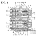
- the first and second connector housings 10, 10' are connected with each other by engaging the second coupling portions 28 of the upper or first connector housing 10' with the first coupling portions 18 of the lower or second connector housing 10 from front in FIG. 1. During this connecting operation, the first locking portions 16 of the lower connector housing 10 move in the front guide groove 27F of the upper connector housing 10'.
- the elastic locking piece 22 of the upper connector housing 10' is substantially elastically displaced upward (direction closer to the upper surface 10L of the upper connector housing 10' and toward the inside of the insertion space 23) by the inclination of the guide surfaces 16F, 26R, and the second locking portion 26 of this elastic locking piece 22 moves over the first locking portion 16 of the lower connector housing 10.
- the elastic locking piece 22 is elastically restored substantially to its original position to engage the locking surface 26F of the second locking portion 26 with the locking surface 16R of the first locking portion 16. This prevents the upper connector housing 10' from being disengaged forward from the lower connector housing 10. Simultaneously, the rear ends of the second coupling portions 28 of the upper connector housing 10' come into abutment against the first stoppers 19 of the first coupling portions 18 of the lower connector housing 10, and the second stoppers 29 of the second coupling portions 28 come into abutment against the front ends of the first coupling portions 18.
- the narrow jig J in the form of a flat or minus screwdriver is opposed to an insertion opening 30 defined between the connector housings 10, 10' as shown in FIG. 3, the jig J is or can be inserted between the elastic locking piece 22 and the upper surface 10U of the lower connector housing 10, i.e. into the escape recess 17 through the insertion opening 30 and the leading end thereof is inclined upward with respect to the inserting direction (toward the elastic locking piece 22).
- a point of inclination at this time is the front end (end toward the insertion opening 30) of the escape recess 17.
- the leading end of the jig J pushes or can push the elastic locking piece 22 in a position slightly before the first locking portion 16 to forcibly elastically displace the elastic locking piece 22 upward.
- the first locking portion 16 and the second locking portion 26 are or can be disengaged from each other to permit the connector housings 10, 10' to relatively move in their disengaging direction.
- the connector housings 10, 10' are disengaged by sliding the upper connector housing 10 forward as shown in FIG. 5 while keeping the first and second locking portions 16, 26 disengaged.
- the lower surface 10L of the connector housing 10 is brought closer to the stay S horizontally projecting backward or projecting in a specified (predetermined or predeterminable) direction toward the connector housing 10 to at least partly fit the stay S into the insertion space 23.
- the leading end (rear end) of the stay S comes into contact with the guide surface 24F of the stay locking portion 24 to substantially elastically displace the elastic locking piece 22 downward (direction away from the lower surface 10L of the connector housing 10 and opposite from the insertion space 23) by the inclination of the guide surface 24F.
- the contact portions Sa of the stay S come into contact with the front end surfaces of the opposite ends of the plate portion 20 to restrict any further insertion of the stay S into the insertion space 23, and the elastic locking piece 22 is elastically restored substantially to its original position to engage the stay locking portion 24 with the locking hole Sc.
- the locking surface 24R of the stay locking portion 24 is engaged with the rear edge of the locking hole Sc from front, with the result that the connector housing 10 is prevented from being disengaged backward from the stay S. In this way, the connector housing 10 is locked into the stay S while making it impossible to withdraw or further insert the stay S from or into the connector housing 10.
- a finger or manipulating jig is or can be placed on the rear end (free end) of the elastic locking piece 22 to forcibly elastically displace the elastic locking piece 22 downward (direction away from the lower surface 10L of the connector housing 10). Then, as shown in FIG. 6, the stay locking portion 24 is disengaged from the locking hole Sc of the stay S.
- the connector housing 10 can be detached from the stay S by being moved backward while keeping the stay locking portion 24 and the locking hole Sc disengaged.
- the upper surface 10U of the connector housing 10 is formed with the first locking portion 16 as the connecting means for the connector housings 10, whereas the lower surface 10L thereof is formed with the elastic locking piece 22 provided with the second locking portion 26 as the connecting means for the connector housings 10, 10' and the stay locking portion 24 as the mounting means for mounting the connector housing 10 on the stay S.
- a plurality of connector housings 10 can be mounted on one stay S while being connected with each other.
- the two mating connector housings 10, 10' have identical or similar shape and/or configuration.
- the inserting direction of the stay S into the insertion space 23 is the same as the extending direction of the elastic locking piece 22 from its point of pivotal movement toward the extending end, the base end (front end) of the stay S extends out of the insertion space 23 in a direction opposite from the extending end (rear end) of the elastic locking piece 22 with the stay S inserted in the insertion space 23. Accordingly, a finger or the jig J can be placed on the extending end of the elastic locking piece 22 without any interference with the stay S to disengage the stay locking portion 24 of the elastic locking piece 22 and the stay S from each other.
- the insertion opening 30 of the connector housing 10 for the jig J is formed at the side preferably substantially opposite from the wire draw-out surface 14 of the connector housing 10, and the jig J is or can be inserted from the side substantially opposite from the one where the wires 13 are drawn out. Thus, the wires 13 do not interfere the insertion of the jig J.
- the jig J is inclined to incline the elastic locking piece 22.
- the inserting direction of the stay S into the connector housing 10 is substantially the same as the extending direction of the elastic locking piece 22 from its point of pivotal movement toward the extending end, a point of inclination of the jig J and that of the elastic locking piece 22 are located substantially at the same position with respect to the forward and backward directions. Therefore, the jig J can be held substantially along the elastic locking piece 22.
- the escape recess 17 for permitting the inclining movement of the jig J to incline the elastic locking piece 22 is formed in the upper surface 10U of the connector housing 10, a clearance between the upper surface 10U (where the first locking portion 16 is formed) of the lower connector housing 10 and the lower surface of the elastic locking piece 22 of the upper connector housing 10' can be narrowed with the upper and lower connector housings 10 connected with each other.
Landscapes
- Connector Housings Or Holding Contact Members (AREA)
- Details Of Connecting Devices For Male And Female Coupling (AREA)
- Connection Of Plates (AREA)
- Snaps, Bayonet Connections, Set Pins, And Snap Rings (AREA)
- Installation Of Indoor Wiring (AREA)
Abstract
Description
- The present invention relates to a connector housing and to a connector provided with two or more such connector housings.
- In the case that a wiring harness is arranged in an engine compartment of an automotive vehicle, a specified arrangement path has been secured by fixing connector housings forming the wiring harness to a vehicle body. A means shown in FIG. 11 has been conventionally adopted to fix the connector housings to the vehicle body.
- This means is such that a plate-
shaped stay 2 formed with amount hole 3 is provided on abody 1, a projection 5 engageable with themount hole 3 is formed on the bottom surface of a connector housing,guides 6 having a hook-shaped cross section are formed at the opposite sides of the projection 5, and the connector housing 4 is mounted on thestay 2 by sliding thehooked guides 6 while fitting them to the opposite side edges of thestay 2. - With the means for mounting one connector housing 4 on the
body 1 via onestay 2 as described above, not only the number ofstays 2 increases, but also thebody 1 is required to have a space for arranging a plurality ofstays 2 in the case that a plurality of wiring harnesses are arranged in the engine compartment. - In view of the above situation, an object of the present invention is to enable a plurality of connector housings to be mounted on a mating mounting member by one stay.
- This object is solved according to the invention by a connector housing according to
claim 1 and by a connector according toclaim 10. Preferred embodiments of the invention are subject of the dependent claims. - According to the invention, there is provided a connector housing connectable with a mating connector housing, having one or more terminal fittings accommodated therein, and being mountable on a mating mounting member via a stay, wherein the connector housing is formed with:
- at least one first coupling portion,
- at least one second coupling portion for connecting the connector housing with the mating connector housing by being engaged with a corresponding first coupling portion of the mating connector housing,
- at least one first locking portion, and
- at least one elastic locking piece extending substantially along the outer surface of the connector housing while being spaced apart therefrom to define an insertion space for the stay and elastically deformable to incline toward and away from the connector housing, wherein a stay locking portion for preventing the stay from being withdrawn from the insertion space by engaging the stay is formed on an inner surface of the elastic locking piece facing or on the side of the insertion space, and a second locking portion for preventing the connector housing from being disengaged from the mating connector housing by engaging the first locking portion is formed on an outer surface of the elastic locking piece substantially opposite from the insertion space.
-
- According to a preferred embodiment of the invention, there is provided a connector provided with connector housings connectable with each other and terminal fittings accommodated in the connector housings, and mountable on a mating mounting member via a stay, wherein outer surfaces of each connector housing are formed with:
- a first coupling portion,
- a second coupling portion for connecting two connector housings with each other by being engaged with the first coupling portion of the other connector housing,
- a first locking portion, and
- an elastic locking piece extending along the outer surface of the connector housing while being spaced apart therefrom to define an insertion space for the stay and elastically deformable to incline toward and away from the outer surface of the connector housing, wherein a stay locking portion for preventing the stay from being withdrawn from the insertion space by engaging the stay is formed on an inner surface of the elastic locking piece facing the insertion space, and a second locking portion for preventing the connector housings from being disengaged from each other by engaging the first locking portion is formed on an outer surface of the elastic locking piece opposite from the insertion space.
-
- The connector housings connected with each other are prevented from being disengaged from each other by engaging the first coupling portion of one connector housing with the second coupling portion of the other connector housing. The connector housing is mounted on the stay by inserting the stay into the insertion space to be engaged with the stay locking portion.
- According to a further preferred embodiment of the invention, an inserting direction of the stay into the insertion space is the substantially same as an extending direction of the elastic locking piece from its point of pivotal movement toward its extending end.
- With the stay inserted in the insertion space, the base end of the stay extends out of the insertion space toward the side opposite from the extending end of the elastic locking piece. Accordingly, a finger or a jig can be placed on the extending end of the elastic locking piece without any interference with the stay to disengage the stay locking portion of the elastic locking piece and the stay from each other.
- Preferably, a jig can be inserted between the connector housing and the mating connector housing connected therewith and incline the elastic locking piece in a direction to bring the second locking portion away from the first locking portion.
- Thus, a jig can be inserted between the two connector housings connected with each other and incline the elastic locking piece in a direction to bring the second locking portion away from the first locking portion, and an insertion opening of the connector housing for the jig is preferably provided at a side opposite from a wire draw-out surface of the connector.
- Since the jig is or can be inserted from the side opposite from the one where the wires are drawn out, the wires do not interfere the insertion of the jig.
- Further preferably, a jig can be inserted between the two connector housings connected with each other and incline the elastic locking piece in a direction to bring the second locking portion away from the first locking portion, and an inserting direction of the jig into the connector housing is preferably substantially the same as an extending direction of the elastic locking piece from its point of pivotal movement toward its extending end.
- The jig is inclined to incline the elastic locking piece. Since a point of inclination of the jig and that of the elastic locking piece are located substantially at the same position at this time, the jig can be held substantially along the elastic locking piece.
- Still further preferably, an escape recess for permitting an inclining movement of the jig to incline the elastic locking piece is formed in the outer surface of the connector housing where the first locking portion is formed.
- By forming the escaping recess, a clearance between the outer surface where the first locking portion is formed and the outer surface where the elastic locking piece is formed can be narrowed.
- Further preferably, the escape recess is inclined with respect to an insertion direction of the jig into the insertion opening of the connector housing.
- Still further preferably, the first coupling portion comprises at least one first stopper portion which can come substantially into abutment with a corresponding second coupling portion of the mating connector housing.
- Most preferably, the second coupling portion comprises at least one second stopper portion which can come substantially into abutment with a corresponding first coupling portion of the mating connector housing, wherein first and second stopper portions preferably come into abutment with the corresponding second and first coupling portion, respectively substantially simultaneously.
- Accordingly, a loose movement of the connector housings, in particular in the mating direction, is restricted.
- According to the invention, there is further provided a connector comprising two or more connector housings according to the invention or an embodiment thereof being connectable with each other, wherein at least one of the connector housings is mountable to a mating mounting member by means of a stay.
- These and other objects, features and advantages of the present invention will become apparent upon reading of the following detailed description of preferred embodiments and accompanying drawings in which:
- FIG. 1 is a section showing a state where connector housings of a connector according to one preferred embodiment of the invention are connected and the connector is mounted on a stay,
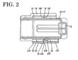
- FIG. 2 is a section of the connector housing according to one preferred embodiment of the invention,
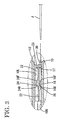
- FIG. 3 is a partial section showing a state before the connector housings are unlocked,
- FIG. 4 is a partial section showing an intermediate state while the connector housings are being unlocked,
- FIG. 5 is a partial section showing a state where the connector housings are unlocked,
- FIG. 6 is a partial section showing a state where an elastic locking piece and a stay are unlocked,
- FIG. 7 is a plan view of the connector housing,
- FIG. 8 is a bottom view of the connector housing,
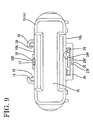
- FIG. 9 is a front view of the connector housing,
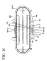
- FIG. 10 is a rear view of the connector housing, and
- FIG. 11 is a section of a prior art means for mounting a connector on a stay.
-
- Hereinafter, one preferred embodiment of the invention is described with reference to FIGS. 1 to 10.
- A connector or connector housing according to this embodiment is mountable on a mating mounting member A via a stay S. The stay S is substantially plate-shaped and is horizontally secured while its leading end portion projects from an end of the upper surface of the mating mounting member A (see FIGS. 1 and 6). The stay S is substantially rectangular in plan view as a whole as shown by phantom line in FIG. 8, and is stepped or narrowed at the opposite side or lateral edges such that the leading end portion to be engaged with a
connector housing 10 is narrower than the base end portion. The stepped or narrowed portions serve as contact portions Sa. A narrow portion Sb of the stay S is formed with a substantially rectangular locking hole Sc located in a widthwise center position. - A connector is a so-called joint connector and is comprised of a
connector housing 10, a plurality of harness-side terminal fittings 11 to be at least partly inserted into the connector housing 10 preferably from behind, and a joint terminal fitting 12 for electrically connecting the plurality of harness-side terminal fittings 11 inside theconnector housing 10.Wires 13 connected with the harness-side terminal fittings 11 are drawn out backward preferably through the rear end surface, i.e. a wire draw-out surface orportion 14, of theconnector housing 10. - In the description below, right side in FIGS. 1 to 8 is referred to as front and vertical direction is based on FIGS. 1 to 6.
- The
connector housing 10 is, as a whole, preferably in the form of a substantially flat rectangular parallelepiped whose width is larger than its height, and the front end thereof is or can be closed by afront wall 15. On a substantially flat upper orfirst surface 10U of theconnector housing 10, afirst locking portion 16 is formed preferably substantially in a middle position with respect to widthwise direction and forward and backward directions. Thefirst locking portion 16 is in the form of a projection, and the front surface thereof is formed into aguide surface 16F which is inclined with respect to theupper surface 10U of theconnector housing 10, i.e. to forward and backward directions (disengaging direction from a mating connector housing 10) while the rear surface thereof is formed into alocking surface 16R which extends upward from theupper surface 10U of theconnector housing 10 at an angle different from 0° or 180°, preferably substantially at a right angle or in an overhanging manner. - In the
upper surface 10U of the connector housing 10, anescape recess 17 is formed in a position before thefirst locking portion 16. This escape recess 17 is narrow in forward and backward directions and inclined downward to the front. In other words, theescape recess 17 is deeper toward its front end. The left and right inner surfaces of theescape recess 17 are so inclined as to be wider toward the upper end when viewed from front or so that the escape recess 17 is at its upper end wider toward the front of theconnector housing 10 while being substantially of equal width at its bottom end (FIG. 7). Accordingly, theescape recess 17 has substantially V-shape or bottomed V-shape when seen in cross-section. The bottom surface of theescape recess 17 has a substantially constant width over its entire length along forward and backward directions, and this width is substantially equal to that of thefirst locking portion 16. - A pair of left and right or lateral
first coupling portions 18 are formed at the opposite sides of thefirst locking portion 16 on theupper surface 10U of theconnector housing 10. Eachcoupling portion 18 has, as can be seen in FIG. 9, substantially an L-shaped (hook-shaped) cross section bent inwardly when viewed from front, and substantially linearly extends in forward and backward directions (fitting directions of the connector housings 10). Further, afirst stopper 19 is formed at the rear end of thefirst coupling portion 18. - A substantially
rectangular plate portion 20 is formed preferably substantially in a widthwise center position of a substantially flat lower orsecond surface 10L of theconnector housing 10. Theplate portion 20 is substantially continuous with thelower surface 10L of theconnector housing 10 at its opposite side edges and is substantially parallel to thelower surface 10L of theconnector housing 10. A pair of left and right orlateral slits 21 are formed preferably substantially in a widthwise middle portion of theplate portion 20, thereby forming anelastic locking piece 22 which cantilevers backward substantially in parallel with thelower surface 10L of theconnector housing 10. Thiselastic locking piece 22 extends along thelower surface 10L of theconnector housing 10 while being spaced apart therefrom to define aninsertion space 23 for the stay S, and is elastically deflectable or deformable substantially in directions (vertical direction) toward and away from thelower surface 10L of theconnector housing 10. - On the inner surface (upper surface) of the
elastic locking piece 22 substantially facing or corresponding to theinsertion space 23, astay locking portion 24 in the form of a projection is formed to prevent the stay S from being withdrawn from theinsertion space 23 by locking the stay S. The front surface of thestay locking portion 24 is formed into aguide surface 24F which is inclined with respect to forward and backward directions (inserting direction of the stay S into the insertion space 23), and the rear surface thereof is formed into a lockingsurface 24R which extends preferably at a substantially right angle to or overhangs from theupper surface 10U of theconnector housing 10. - On the other hand, a
second locking portion 26 in the form of a projection engageable with thefirst locking portion 16 is formed on the outer (lower surface) of theelastic locking piece 22 at the side opposite from theinsertion space 23. The front surface of thesecond locking portion 26 is formed into a lockingsurface 26F which extends preferably at a right angle to or overhangs with respect to forward and backward directions (disengaging direction from the mating connector housing 10), and the rear surface thereof is formed into aguide surface 26R which is inclined with respect to forward and backward directions (fitting direction with the mating connector housing 10). Further, guidegrooves second locking portion 26 are formed in the lower surface of theelastic locking piece 22. - The opposite side edges of the
plate portion 20 are rib-shapedsecond coupling portions 28 projecting outwardly with respect to widthwise direction and linearly extending preferably substantially in parallel in forward and backward directions. Thesecond coupling portions 28 are slidably engageable with the grooves of thefirst coupling portions 18 of themating connector housing 10 in forward and backward directions. Further,second stoppers 29 are formed at the front ends of thesecond coupling portions 28. - Here, the directions of the respective members are collectively described. The extension of the
elastic locking piece 22 is substantially the same as a direction in which theconnector housing 10 formed with theelastic locking piece 22 is fitted to the mating (upper in FIG. 1)connector housing 10 by the lockingportion 16. The extension of theelastic locking piece 22 is substantially the same as a direction in which the stay S is inserted into theinsertion space 23. The extension of theelastic locking piece 22 is substantially the same as a direction in which a jig J is inserted into theconnector housing 10. The inserting direction of the stay S into theinsertion space 23 is substantially the same as the inserting direction of the jig J into theconnector housing 10. A direction in which thewires 13 are drawn out from theconnector housing 10 is substantially the same as the extension of theelastic locking piece 22. The drawing direction of thewires 13 from theconnector housing 10 is substantially the same as the inserting direction of the stay S into theinsertion space 23. The drawing direction of thewires 13 from theconnector housing 10 is substantially the same as the inserting direction of the jig J into theconnector housing 10. - Next, the action of this embodiment is described.
- The first and
second connector housings 10, 10' are connected with each other by engaging thesecond coupling portions 28 of the upper or first connector housing 10' with thefirst coupling portions 18 of the lower orsecond connector housing 10 from front in FIG. 1. During this connecting operation, thefirst locking portions 16 of thelower connector housing 10 move in thefront guide groove 27F of the upper connector housing 10'. Subsequently, when the guide surfaces 16F, 26R of the first andsecond locking portions elastic locking piece 22 of the upper connector housing 10' is substantially elastically displaced upward (direction closer to theupper surface 10L of the upper connector housing 10' and toward the inside of the insertion space 23) by the inclination of the guide surfaces 16F, 26R, and thesecond locking portion 26 of thiselastic locking piece 22 moves over thefirst locking portion 16 of thelower connector housing 10. - When the
connector housings 10, 10' are substantially properly connected, theelastic locking piece 22 is elastically restored substantially to its original position to engage thelocking surface 26F of thesecond locking portion 26 with the lockingsurface 16R of thefirst locking portion 16. This prevents the upper connector housing 10' from being disengaged forward from thelower connector housing 10. Simultaneously, the rear ends of thesecond coupling portions 28 of the upper connector housing 10' come into abutment against thefirst stoppers 19 of thefirst coupling portions 18 of thelower connector housing 10, and thesecond stoppers 29 of thesecond coupling portions 28 come into abutment against the front ends of thefirst coupling portions 18. These two abutments restrict any further loose movement of theconnector housings 10, 10' in the fitting direction (any further backward movement of thelower connector housing 10 with respect to the upper connector housing 10'). In this way, theconnector housings 10, 10' are locked into each other while having their relative movements in forward and backward directions restricted. - When the
connector housings 10, 10' are to be disengaged from each other, the narrow jig J in the form of a flat or minus screwdriver is opposed to aninsertion opening 30 defined between theconnector housings 10, 10' as shown in FIG. 3, the jig J is or can be inserted between theelastic locking piece 22 and theupper surface 10U of thelower connector housing 10, i.e. into theescape recess 17 through theinsertion opening 30 and the leading end thereof is inclined upward with respect to the inserting direction (toward the elastic locking piece 22). A point of inclination at this time is the front end (end toward the insertion opening 30) of theescape recess 17. When the jig J is inclined as above, the leading end of the jig J pushes or can push theelastic locking piece 22 in a position slightly before thefirst locking portion 16 to forcibly elastically displace theelastic locking piece 22 upward. As a result, thefirst locking portion 16 and thesecond locking portion 26 are or can be disengaged from each other to permit theconnector housings 10, 10' to relatively move in their disengaging direction. Theconnector housings 10, 10' are disengaged by sliding theupper connector housing 10 forward as shown in FIG. 5 while keeping the first andsecond locking portions - When the
connector housing 10 is to be mounted on the stay S, thelower surface 10L of theconnector housing 10 is brought closer to the stay S horizontally projecting backward or projecting in a specified (predetermined or predeterminable) direction toward theconnector housing 10 to at least partly fit the stay S into theinsertion space 23. During this fitting operation, the leading end (rear end) of the stay S comes into contact with theguide surface 24F of thestay locking portion 24 to substantially elastically displace theelastic locking piece 22 downward (direction away from thelower surface 10L of theconnector housing 10 and opposite from the insertion space 23) by the inclination of theguide surface 24F. When theconnector housing 10 reaches its proper mount position on the stay S, the contact portions Sa of the stay S come into contact with the front end surfaces of the opposite ends of theplate portion 20 to restrict any further insertion of the stay S into theinsertion space 23, and theelastic locking piece 22 is elastically restored substantially to its original position to engage thestay locking portion 24 with the locking hole Sc. The lockingsurface 24R of thestay locking portion 24 is engaged with the rear edge of the locking hole Sc from front, with the result that theconnector housing 10 is prevented from being disengaged backward from the stay S. In this way, theconnector housing 10 is locked into the stay S while making it impossible to withdraw or further insert the stay S from or into theconnector housing 10. - When the
connector housing 10 is to be detached from the stay S, a finger or manipulating jig is or can be placed on the rear end (free end) of theelastic locking piece 22 to forcibly elastically displace theelastic locking piece 22 downward (direction away from thelower surface 10L of the connector housing 10). Then, as shown in FIG. 6, thestay locking portion 24 is disengaged from the locking hole Sc of the stay S. Thus, theconnector housing 10 can be detached from the stay S by being moved backward while keeping thestay locking portion 24 and the locking hole Sc disengaged. - As described above, in this embodiment, the
upper surface 10U of theconnector housing 10 is formed with thefirst locking portion 16 as the connecting means for theconnector housings 10, whereas thelower surface 10L thereof is formed with theelastic locking piece 22 provided with thesecond locking portion 26 as the connecting means for theconnector housings 10, 10' and thestay locking portion 24 as the mounting means for mounting theconnector housing 10 on the stay S. Thus, a plurality ofconnector housings 10 can be mounted on one stay S while being connected with each other. Preferably, the twomating connector housings 10, 10' have identical or similar shape and/or configuration. - Further, since the inserting direction of the stay S into the
insertion space 23 is the same as the extending direction of theelastic locking piece 22 from its point of pivotal movement toward the extending end, the base end (front end) of the stay S extends out of theinsertion space 23 in a direction opposite from the extending end (rear end) of theelastic locking piece 22 with the stay S inserted in theinsertion space 23. Accordingly, a finger or the jig J can be placed on the extending end of theelastic locking piece 22 without any interference with the stay S to disengage thestay locking portion 24 of theelastic locking piece 22 and the stay S from each other. - The
insertion opening 30 of theconnector housing 10 for the jig J is formed at the side preferably substantially opposite from the wire draw-outsurface 14 of theconnector housing 10, and the jig J is or can be inserted from the side substantially opposite from the one where thewires 13 are drawn out. Thus, thewires 13 do not interfere the insertion of the jig J. - The jig J is inclined to incline the
elastic locking piece 22. In this embodiment, since the inserting direction of the stay S into theconnector housing 10 is substantially the same as the extending direction of theelastic locking piece 22 from its point of pivotal movement toward the extending end, a point of inclination of the jig J and that of theelastic locking piece 22 are located substantially at the same position with respect to the forward and backward directions. Therefore, the jig J can be held substantially along theelastic locking piece 22. - Further, since the
escape recess 17 for permitting the inclining movement of the jig J to incline theelastic locking piece 22 is formed in theupper surface 10U of theconnector housing 10, a clearance between theupper surface 10U (where thefirst locking portion 16 is formed) of thelower connector housing 10 and the lower surface of theelastic locking piece 22 of the upper connector housing 10' can be narrowed with the upper andlower connector housings 10 connected with each other. - The present invention is not limited to the above described and illustrated embodiment. For example, the following embodiments are also embraced by the technical scope of the present invention as defined in the claims. Beside the following embodiments, various changes can be made without departing the sprit of the present invention as defined in the claims.
- (1) Although the present invention is applied to the joint connector to be mounted on an end of a wiring harness in the foregoing embodiment, it is also applicable to so-called wire-to-wire type connectors provided in intermediate positions of wiring harnesses.
- (2) Although the extension of the
elastic locking piece 22 according to the foregoing embodiment is substantially the same as the fitting direction of theconnector housing 10 formed with theelastic locking piece 22 with the mating connector housing 10' (upper connector housing in FIG. 1) by thefirst locking portion 16, the two directions may be opposite from each other according to the present invention. - (3) Although the extension of the
elastic locking piece 22 is substantially the same as the inserting direction of the stay S into theinsertion space 23 in the foregoing embodiment in the foregoing embodiment, the two directions may be opposite from each other according to the present invention. - (4) Although the extension of the
elastic locking piece 22 is substantially the same as the inserting direction of the jig J into theconnector housing 10, 10' in the foregoing embodiment, the two directions may be opposite from each other according to the present invention. - (5) Although the inserting direction of the stay S into the
insertion space 23 is substantially the same as the inserting direction of the jig J into theconnector housing 10, 10' in the foregoing embodiment, the two directions may be opposite from each other according to the present invention. - (6) Although the drawing direction of the wires from the connector housing is the same as the extension of the elastic locking piece in the foregoing embodiment, the two directions may be opposite from each other according to the present invention.
- (7) Although the drawing direction of the
wires 13 from theconnector housing 10 is the same as the inserting direction of the stay S into theinsertion space 23 in the foregoing embodiment, the two directions may be opposite from each other according to the present invention. - (8) Although the drawing direction of the
wires 13 from theconnector housing 10, 10' is substantially the same as the inserting direction of the jig J into theconnector housing 10, 10' in the foregoing embodiment, the two directions may be opposite from each other according to the present invention. - (9) Although both first and
second locking portions - (10) Although the
stay locking portion 24 is a projection and the locking portion Sc of the stay S is a hole in the foregoing embodiment, thestay locking portion 24 may be a hole and the locking portion Sc of the stay S may be a projection according to the present invention. - (11) Although the first and
second locking portions connector housing 10, 10' opposite to each other in the foregoing embodiment, the outer surface where thefirst locking portion 16 is formed and the one where thesecond locking portion 26 is formed may be arranged at an angle different from 0° or 180°, preferably substantially normal to each other. -
-
- 10
- connector housing
- 10'
- mating connector housing
- 11, 12
- terminal fitting
- 13
- wire
- 14
- wire draw-out surface
- 16
- first locking portion
- 17
- escape recess
- 18
- first coupling portion
- 22
- elastic locking piece
- 23
- insertion space
- 24
- stay locking portion
- 26
- second locking portion
- 28
- second coupling portion
- 30
- jig insertion opening between connector housings
- A
- mating mounting member
- S
- stay
Claims (10)
- A connector housing (10) connectable with a mating connector housing (10'), having one or more terminal fittings accommodated therein, and being mountable on a mating mounting member (A) via a stay (S), wherein the connector housing (10) is formed with:at least one first coupling portion (18),at least one second coupling portion (28) for connecting the connector housing (10) with the mating connector housing (10') by being engaged with a corresponding first coupling portion (18) of the mating connector housing (10'),at least one first locking portion (16), andat least one elastic locking piece (22) extending substantially along the outer surface of the connector housing (10) while being spaced apart therefrom to define an insertion space (23) for the stay (S) and elastically deformable to incline toward and away from the connector housing (10), wherein a stay locking portion (24) for preventing the stay (S) from being withdrawn from the insertion space (23) by engaging the stay (S) is formed on an inner surface of the elastic locking piece (22) facing the insertion space (23), and a second locking portion (26) for preventing the connector housing (10) from being disengaged from the mating connector housing (10') by engaging the first locking portion (16) is formed on an outer surface of the elastic locking piece (22) substantially opposite from the insertion space (23).
- A connector housing according to claim 1, wherein an inserting direction of the stay (S) into the insertion space (23) is substantially the same as an extending direction of the elastic locking piece (22) from its point of pivotal movement toward its extending end.
- A connector housing according to one or more of the preceding claims, wherein a jig (J) can be inserted between the connector housing (10) and the mating connector housing (10') connected therewith and incline the elastic locking piece (26) in a direction to bring the second locking portion (26) away from the first locking portion (16).
- A connector housing according to claim 3, wherein an insertion opening (30) of the connector housing (10) for the jig (J) is provided at a side opposite from a wire draw-out surface (14) of the connector housing (10).
- A connector housing according to claim 3 or 4, wherein an inserting direction of the jig (J) into the connector housing (10) is substantially the same as an extending direction of the elastic locking piece (22) from its point of pivotal movement toward its extending end.
- A connector housing according to any of claims 3, 4 or 5, wherein an escape recess (17) for permitting an inclining movement of the jig (J) to incline the elastic locking piece (22) is formed in the outer surface of the connector housing (10) where the first locking portion (16) is formed.
- A connector housing according to claim 6, wherein the escape recess (17) is inclined with respect to an insertion direction of the jig (J) into the insertion opening (30) of the connector housing (10).
- A connector housing according to one or more of the preceding claims, wherein the first coupling portion (18) comprises at least one first stopper portion (19) which can come substantially into abutment with a corresponding second coupling portion (28) of the mating connector housing (10').
- A connector housing according to one or more of the preceding claims, wherein the second coupling portion (28) comprises at least one second stopper portion (29) which can come substantially into abutment with a corresponding first coupling portion (16) of the mating connector housing (10'), wherein first and second stopper portions (19, 29) preferably come into abutment with the corresponding second and first coupling portion (28, 18), respectively substantially simultaneously.
- A connector comprising two or more connector housings (10, 10') according to one or more of the preceding claims being connectable with each other, wherein at least one of the connector housings (10, 10') is mountable to a mating mounting member (A) by means of a stay (S).
Applications Claiming Priority (2)
| Application Number | Priority Date | Filing Date | Title |
|---|---|---|---|
| JP2000145934A JP3698250B2 (en) | 2000-05-18 | 2000-05-18 | connector |
| JP2000145934 | 2000-05-18 |
Publications (2)
| Publication Number | Publication Date |
|---|---|
| EP1156553A1 true EP1156553A1 (en) | 2001-11-21 |
| EP1156553B1 EP1156553B1 (en) | 2003-08-27 |
Family
ID=18652369
Family Applications (1)
| Application Number | Title | Priority Date | Filing Date |
|---|---|---|---|
| EP01109964A Expired - Lifetime EP1156553B1 (en) | 2000-05-18 | 2001-04-24 | A connector housing and a connector |
Country Status (4)
| Country | Link |
|---|---|
| US (1) | US6413118B2 (en) |
| EP (1) | EP1156553B1 (en) |
| JP (1) | JP3698250B2 (en) |
| DE (1) | DE60100639T2 (en) |
Families Citing this family (11)
| Publication number | Priority date | Publication date | Assignee | Title |
|---|---|---|---|---|
| JP2003333728A (en) * | 2002-05-10 | 2003-11-21 | Sumitomo Wiring Syst Ltd | Connection structure between junction box and attached electric connection box |
| EP1369959B1 (en) * | 2002-06-06 | 2007-10-24 | Sumitomo Wiring Systems, Ltd. | A connector, a disengagement jig and a method |
| JP2004015958A (en) * | 2002-06-10 | 2004-01-15 | Sumitomo Wiring Syst Ltd | Interconnecting structure of junction box and electric connection box attached therewith |
| JP3838269B1 (en) * | 2005-06-13 | 2006-10-25 | 住友電装株式会社 | Electrical junction box |
| CN2909606Y (en) * | 2006-03-11 | 2007-06-06 | 富士康(昆山)电脑接插件有限公司 | Fixing device for electric connector |
| JP5286166B2 (en) * | 2009-06-17 | 2013-09-11 | 矢崎総業株式会社 | Unlock structure |
| CN202600189U (en) * | 2012-05-31 | 2012-12-12 | 泰科电子(上海)有限公司 | Adapter assembly and connector assembly |
| JP5550766B2 (en) * | 2013-05-31 | 2014-07-16 | 矢崎総業株式会社 | Container with lock arm |
| CN106030925A (en) * | 2013-12-23 | 2016-10-12 | 富加宜(亚洲)私人有限公司 | Electrical connector |
| JP6306486B2 (en) * | 2014-09-30 | 2018-04-04 | 本田技研工業株式会社 | Support structure for multiple couplers |
| JP7132273B2 (en) * | 2020-04-24 | 2022-09-06 | 矢崎総業株式会社 | connector |
Citations (3)
| Publication number | Priority date | Publication date | Assignee | Title |
|---|---|---|---|---|
| US4938710A (en) * | 1987-12-15 | 1990-07-03 | Honda Giken Kogyo Kabushiki Kaisha | Connector apparatus |
| US5048161A (en) * | 1989-05-25 | 1991-09-17 | Yazaki Corporation | Connector with lock onto panel |
| EP0731530A2 (en) * | 1995-03-09 | 1996-09-11 | Sumitomo Wiring Systems, Ltd. | Assembled connector |
Family Cites Families (7)
| Publication number | Priority date | Publication date | Assignee | Title |
|---|---|---|---|---|
| US3577116A (en) * | 1968-08-08 | 1971-05-04 | Molex Inc | Lamp socket and terminal |
| US5295870A (en) * | 1992-12-11 | 1994-03-22 | Electro-Wire Products, Inc. | Modular electrical assembly and removable wedge therefor |
| DE4331212C2 (en) * | 1993-09-10 | 1997-04-30 | Krone Ag | Terminal connection unit |
| JPH08171962A (en) * | 1994-12-15 | 1996-07-02 | Sumitomo Wiring Syst Ltd | Junction box |
| JP3039313B2 (en) | 1995-02-09 | 2000-05-08 | 住友電装株式会社 | Lock mechanism |
| JPH10302879A (en) * | 1997-04-24 | 1998-11-13 | Yazaki Corp | Coupling connector |
| US6179653B1 (en) * | 2000-03-23 | 2001-01-30 | Simula Co. Ltd. | Stacking computer connector |
-
2000
- 2000-05-18 JP JP2000145934A patent/JP3698250B2/en not_active Expired - Lifetime
-
2001
- 2001-04-24 EP EP01109964A patent/EP1156553B1/en not_active Expired - Lifetime
- 2001-04-24 DE DE60100639T patent/DE60100639T2/en not_active Expired - Lifetime
- 2001-05-11 US US09/853,532 patent/US6413118B2/en not_active Expired - Lifetime
Patent Citations (3)
| Publication number | Priority date | Publication date | Assignee | Title |
|---|---|---|---|---|
| US4938710A (en) * | 1987-12-15 | 1990-07-03 | Honda Giken Kogyo Kabushiki Kaisha | Connector apparatus |
| US5048161A (en) * | 1989-05-25 | 1991-09-17 | Yazaki Corporation | Connector with lock onto panel |
| EP0731530A2 (en) * | 1995-03-09 | 1996-09-11 | Sumitomo Wiring Systems, Ltd. | Assembled connector |
Also Published As
| Publication number | Publication date |
|---|---|
| DE60100639D1 (en) | 2003-10-02 |
| JP3698250B2 (en) | 2005-09-21 |
| US20010049223A1 (en) | 2001-12-06 |
| DE60100639T2 (en) | 2004-06-09 |
| EP1156553B1 (en) | 2003-08-27 |
| JP2001326035A (en) | 2001-11-22 |
| US6413118B2 (en) | 2002-07-02 |
Similar Documents
| Publication | Publication Date | Title |
|---|---|---|
| US6840789B2 (en) | Connector and a method of assembling it | |
| EP1923962B1 (en) | A connector and method of preassembling it | |
| KR101973894B1 (en) | Electrical connector with a terminal position assurance device | |
| EP1271705B1 (en) | Connector with open-stopping means for retainer | |
| US6942510B2 (en) | Connector and a connector system | |
| EP0696084A2 (en) | Connector with locking device | |
| KR100939700B1 (en) | Connector assembly with terminal position assurance device | |
| US7014511B2 (en) | Electrical connector | |
| US6497591B2 (en) | Connector | |
| US20020193013A1 (en) | Connector | |
| EP1156553B1 (en) | A connector housing and a connector | |
| US5788536A (en) | Connector having elongated protrusions for securing a connecting terminal therein | |
| US6872093B2 (en) | Terminal fitting and a connector provided therewith | |
| US6824428B2 (en) | Connector | |
| US6851987B2 (en) | Connector | |
| EP1557908A2 (en) | A connector | |
| EP1172895B1 (en) | Connector | |
| EP1601063B1 (en) | A connector device | |
| EP1801925B1 (en) | A connector | |
| US6027378A (en) | Combined-type connector | |
| EP1523072B1 (en) | A connector, a connector assembly and an assembling method | |
| US6835106B2 (en) | Connector, a connector assembly, a jig, and a method for withdrawing a terminal in a connector | |
| US6488547B2 (en) | Connector with longitudinally spaced locks for retaining terminal fittings | |
| US6325663B1 (en) | Half-fitting prevention connector | |
| US6478632B2 (en) | Shake preventing construction for a terminal fitting and a connector |
Legal Events
| Date | Code | Title | Description |
|---|---|---|---|
| PUAI | Public reference made under article 153(3) epc to a published international application that has entered the european phase |
Free format text: ORIGINAL CODE: 0009012 |
|
| 17P | Request for examination filed |
Effective date: 20010517 |
|
| AK | Designated contracting states |
Kind code of ref document: A1 Designated state(s): AT BE CH CY DE DK ES FI FR GB GR IE IT LI LU MC NL PT SE TR Kind code of ref document: A1 Designated state(s): DE |
|
| AX | Request for extension of the european patent |
Free format text: AL;LT;LV;MK;RO;SI |
|
| 17Q | First examination report despatched |
Effective date: 20020215 |
|
| AKX | Designation fees paid |
Free format text: DE |
|
| GRAH | Despatch of communication of intention to grant a patent |
Free format text: ORIGINAL CODE: EPIDOS IGRA |
|
| GRAS | Grant fee paid |
Free format text: ORIGINAL CODE: EPIDOSNIGR3 |
|
| GRAA | (expected) grant |
Free format text: ORIGINAL CODE: 0009210 |
|
| AK | Designated contracting states |
Designated state(s): DE |
|
| REF | Corresponds to: |
Ref document number: 60100639 Country of ref document: DE Date of ref document: 20031002 Kind code of ref document: P |
|
| PLBE | No opposition filed within time limit |
Free format text: ORIGINAL CODE: 0009261 |
|
| STAA | Information on the status of an ep patent application or granted ep patent |
Free format text: STATUS: NO OPPOSITION FILED WITHIN TIME LIMIT |
|
| 26N | No opposition filed |
Effective date: 20040528 |
|
| REG | Reference to a national code |
Ref country code: DE Ref legal event code: R084 Ref document number: 60100639 Country of ref document: DE |
|
| PGFP | Annual fee paid to national office [announced via postgrant information from national office to epo] |
Ref country code: DE Payment date: 20200415 Year of fee payment: 20 |
|
| REG | Reference to a national code |
Ref country code: DE Ref legal event code: R071 Ref document number: 60100639 Country of ref document: DE |