EP1156319A1 - Particle size distribution measuring apparatus - Google Patents
Particle size distribution measuring apparatus Download PDFInfo
- Publication number
- EP1156319A1 EP1156319A1 EP01111427A EP01111427A EP1156319A1 EP 1156319 A1 EP1156319 A1 EP 1156319A1 EP 01111427 A EP01111427 A EP 01111427A EP 01111427 A EP01111427 A EP 01111427A EP 1156319 A1 EP1156319 A1 EP 1156319A1
- Authority
- EP
- European Patent Office
- Prior art keywords
- validation
- particle size
- operator
- size distribution
- measuring apparatus
- Prior art date
- Legal status (The legal status is an assumption and is not a legal conclusion. Google has not performed a legal analysis and makes no representation as to the accuracy of the status listed.)
- Withdrawn
Links
- 239000002245 particle Substances 0.000 title claims abstract description 93
- 238000010200 validation analysis Methods 0.000 claims abstract description 131
- 238000007689 inspection Methods 0.000 claims description 15
- 230000000052 comparative effect Effects 0.000 claims description 3
- 238000000034 method Methods 0.000 abstract description 37
- 239000000523 sample Substances 0.000 description 52
- 238000005259 measurement Methods 0.000 description 30
- 238000002834 transmittance Methods 0.000 description 17
- 230000006870 function Effects 0.000 description 12
- 239000002612 dispersion medium Substances 0.000 description 5
- 238000013208 measuring procedure Methods 0.000 description 5
- 238000012545 processing Methods 0.000 description 5
- 230000003287 optical effect Effects 0.000 description 4
- 238000004891 communication Methods 0.000 description 3
- 238000010276 construction Methods 0.000 description 3
- 239000002609 medium Substances 0.000 description 3
- 239000000919 ceramic Substances 0.000 description 2
- 239000012488 sample solution Substances 0.000 description 2
- 239000004793 Polystyrene Substances 0.000 description 1
- 238000000149 argon plasma sintering Methods 0.000 description 1
- 239000004568 cement Substances 0.000 description 1
- 238000012790 confirmation Methods 0.000 description 1
- 238000001514 detection method Methods 0.000 description 1
- 239000012153 distilled water Substances 0.000 description 1
- 238000002296 dynamic light scattering Methods 0.000 description 1
- 230000010365 information processing Effects 0.000 description 1
- 230000001678 irradiating effect Effects 0.000 description 1
- 239000004816 latex Substances 0.000 description 1
- 229920000126 latex Polymers 0.000 description 1
- 239000000463 material Substances 0.000 description 1
- 239000011859 microparticle Substances 0.000 description 1
- 238000005065 mining Methods 0.000 description 1
- 238000012986 modification Methods 0.000 description 1
- 230000004048 modification Effects 0.000 description 1
- 238000011022 operating instruction Methods 0.000 description 1
- 238000011017 operating method Methods 0.000 description 1
- 229920002223 polystyrene Polymers 0.000 description 1
- 239000000843 powder Substances 0.000 description 1
- 238000003825 pressing Methods 0.000 description 1
- 238000007639 printing Methods 0.000 description 1
- 238000003908 quality control method Methods 0.000 description 1
- 239000002994 raw material Substances 0.000 description 1
- 238000012827 research and development Methods 0.000 description 1
- 239000002904 solvent Substances 0.000 description 1
- XLYOFNOQVPJJNP-UHFFFAOYSA-N water Chemical compound O XLYOFNOQVPJJNP-UHFFFAOYSA-N 0.000 description 1
Images







Classifications
-
- G—PHYSICS
- G01—MEASURING; TESTING
- G01N—INVESTIGATING OR ANALYSING MATERIALS BY DETERMINING THEIR CHEMICAL OR PHYSICAL PROPERTIES
- G01N15/00—Investigating characteristics of particles; Investigating permeability, pore-volume or surface-area of porous materials
- G01N15/02—Investigating particle size or size distribution
-
- G—PHYSICS
- G01—MEASURING; TESTING
- G01N—INVESTIGATING OR ANALYSING MATERIALS BY DETERMINING THEIR CHEMICAL OR PHYSICAL PROPERTIES
- G01N15/00—Investigating characteristics of particles; Investigating permeability, pore-volume or surface-area of porous materials
- G01N15/10—Investigating individual particles
- G01N15/1012—Calibrating particle analysers; References therefor
-
- G—PHYSICS
- G01—MEASURING; TESTING
- G01N—INVESTIGATING OR ANALYSING MATERIALS BY DETERMINING THEIR CHEMICAL OR PHYSICAL PROPERTIES
- G01N2201/00—Features of devices classified in G01N21/00
- G01N2201/12—Circuits of general importance; Signal processing
- G01N2201/127—Calibration; base line adjustment; drift compensation
- G01N2201/12746—Calibration values determination
- G01N2201/12753—Calibration values determination and storage
Definitions
- the present invention relates to a particle (grain) size measuring apparatus, which detects a diffraction/scattered light or dynamic light scattering by irradiating a laser beam to a particle group such as a dispersing powder sample or the like, and measures a particle size distribution of the particle group on the basis of a scattered light intensity signal or the like obtained by the detection.
- a particle size distribution measuring apparatus using light diffraction phenomenon or scattering phenomenon by a particle has calculated a particle size distribution of sample particle in the following manner. More specifically, the above apparatus measures intensity distribution of a diffraction light or a scattered light, that is, a relation between a diffraction angle or scattering angle and a light intensity, and then, carries out arithmetic processing based on a Frauunhofer diffraction theory or Mie scattering theory with respect to the measured result. In the above manner, the above apparatus has calculated the particle size distribution of sample particle.
- the above particle size distribution measuring apparatus has been used for research and development of raw materials in almost mining and industrial fields such as cement or ceramic industry, and in a new material field mainly using ceramics.
- FIG. 16 is a view schematically showing a construction of the particle size distribution measuring apparatus disclosed in this Publication.
- a reference numeral 10 denotes a cell comprising a transparent container for receiving a sample solution 11 dispersing a particle group of measuring object in a proper dispersion medium
- a reference numeral 12 denotes a laser beam source provided on one side (backward side) of the cell 10.
- a parallel laser beam 13 emitted from the laser beam source 12 is enlarged by a beam expander (not shown), and then, is irradiated to the cell 10 in an enlarged state.
- a reference numeral 14 denotes a condenser lens provided on the other side (forward side) of the cell 10, and a ring detector 15 is arranged at a focal position of the condenser lens 14.
- the ring detector 15 is constructed in a manner that a plurality of photo sensors having mutually different radius and a ring or semi-ring light receiving plane is arrayed concentrically around an optical axis of the condenser lens 14. Further, the ring detector 15 receives a light scattered/diffracted at a relatively small angle of the laser beam 13 diffracted or scattered by particles in the cell 10 for each scattering angle, and then, measures their light intensity.
- a wide angle scattered light photo detector group 16 is provided at the vicinity of the cell 10.
- the wide angle scattered light photo detector group 16 individually detects a light scattered/diffracted at a relatively large angle of the laser beam 13 diffracted/scattered by the particles in the cell 10 for each scattered light.
- the wide angle scattered light photo detector group 16 is composed of a plurality of photo sensors 17 to 22 provided at an angle different from the condenser lens 14 and the ring detector 15.
- the photo detector group 16 can detect a wide angle scattered light exceeding a predetermined angle by the particles in the cell 10 in accordance with each oriented angle.
- the photo sensors 17 to 20 detect a forward scattering light
- the photo sensor 21 detects a side scattering light
- the photo sensor 22 detects a backscattering light.
- a reference numeral 23 denotes a pre-amplifier for amplifying an output of the photo sensors constituting the ring detector 15, and a reference numeral 24 denotes a pre-amplifier for amplifying each output of the forward scattering light photo sensors 17 to 20. Further, a reference numeral 25 denotes a pre-amplifier for amplifying each output of the side scattering light photo sensor 21 and the backscattering light photo sensor 22.
- a reference numeral 26 denotes a multiplexer for successively capturing each output of the pre-amplifier groups 23 to 25 and transmitting it to an A-D converter 27, and a reference numeral 28 denotes a computer which is used as an arithmetic processor for inputting an output from the A-D converter 27.
- the computer 28 stores a program for processing each output converted into a digital signal (digital data relative to light intensity) of the ring detector 15 and the photo sensors 13 to 22 on the basis of a Frauunhofer diffraction theory or Mie scattering theory, and obtaining a particle size distribution in a particle group.
- the laser beam 13 in a state that the sample solution 11 is received in the cell 10, when the laser beam 13 is irradiated from the laser beam source 12 to the sample cell 10, the laser beam 13 is diffracted or scattered by the particles in the cell 10.
- a light having a relatively small scattering angle is imaged on the ring detector 15 by the condenser lens 14.
- the photo sensor arranged on the outer side receives a light having a larger scattering angle; on the other hand, the photo sensor arranged on the inner side receives a light having a smaller scattering angle.
- a light intensity detected by the outer-side photo sensor means a quantity of particle having smaller particle diameter (particle size); on the other hand, a light intensity detected by the inner-side photo sensor means a quantity of sample particle having larger particle diameter.
- the light intensity detected by each of these photo sensors is converted into an analog electric signal, and further, is inputted to the multiplexer 26 via the pre-amplifier 23.
- a light which is not converged by the condenser lens 14 and has a relatively large scattering angle, is detected by the photo sensors 17 to 22, and then, its light intensity distribution is measured.
- the forward scattering light photo sensors 17 to 20 the side scattering light photo sensor 21 and the backscattering light photo sensor 22 successively detect a scattering light from a particle having a small particle size.
- the light intensity detected by each of these photo sensors 17 to 22 is converted into an analog electric signal, and further, is inputted to the multiplexer 26 via the pre-amplifier groups 24 and 25.
- the multiplexer 26 captures a measurement data from the ring detector 15 and the photo sensors 17 to 22, that is, an analog electrical signal in a predetermined order.
- the analog electric signal captured by the multiplexer 26 is made into a serial signal, then, is converted by the A-D converter 27 into a digital signal in succession, and thereafter, is inputted to the computer 28.
- the computer 28 processes a light intensity data for each scattering angle obtained by each of the ring detector 15, the photo sensors 17 to 22 on the basis of a Frauunhofer diffraction theory or Mie scattering theory.
- a light intensity distribution of scattering light having a mainly larger particle size is measured by the ring detector 15; on the other hand, a light intensity distribution of wide-angle scattering light having a mainly smaller particle size is measured by the photo sensors 17 to 22. Further, the output of these ring detector 15 and photo sensors 17 to 22 is processed by the computer 28. Therefore, it is possible to obtain a particle size distribution of particle group over a wide range from a relatively larger particle size to a micro particle size.
- the particle size distribution measuring apparatus as described above requires periodically carrying out a validation work in order to make a decision whether or not its measuring accuracy is correctly made.
- the validation work must be correctly done at least one time per year.
- the above scattering type particle size distribution measuring apparatus uses precision optical components, laser beam source, a motor and the like; for this reason, there is a possibility that an accident happens in the case where a user disassemble the apparatus in error, or makes a handling mistake.
- caution matters has been prescribed in a manual or the like, or a label describing handling caution matters has been stuck onto the apparatus main body.
- the aforesaid accident happens due to user's careless mistake and an erroneous operation by an inexperienced operator; for this reason, there is a possibility that the number of many processes is required in a maker side or user side.
- the present invention has been made in view of the aforesaid problems in the related art. It is, therefore, an object of the present invention to provide a particle size distribution measuring apparatus, which has a function of informing an operator of a procedure of validation work of the particle size distribution measuring apparatus, and thereby, can prevent a generation of mistake in a complicate validation work.
- the present invention provides a particle size distribution measuring apparatus comprising a storage medium for storing validation procedure data being used to carry out validation procedures for the particle size distribution measuring apparatus, and a control unit for controlling the validation procedures by successively reading validation procedure data from the storage medium and controlling the particle size distribution measuring apparatus according to the read out validation procedure data to execute the respective validation procedure, wherein the control unit carries out a validation procedure itself, if no operation by an operator in the validation procedure is required, and provides help to the operator when an operation by the operator is required in a validation procedure.
- the operator uses a validation help function provided by the control unit, and thereby, can operate the particle size distribution measuring apparatus according to the help information provided by the control unit which preferably comprises the teaching of work procedures given from the control unit in the predetermined order without making a mistake.
- the measuring procedure controlled by only control unit is automatically carried out, by which the control unit controls the particle size distribution measuring apparatus according to an operation sequence previously stored as a validation data.
- the measuring procedure automatically carried out by the control unit includes a procedure for setting a setup value of measuring object sample such as a refractive index of standard sample used for the validation work. Therefore, the operator has no need of carrying out trouble some various setup operations for the validation work.
- the operator can perform the complicate validation work without referring to a manual, and thereby, it is possible to reduce a load acting to the operator to the minimum, and to successively carry out the validation work made by the operator during the validation procedures step by step without making a mistake. This serves to more accurately perform the validation work.
- control unit has a warning function of pointing out the operator's mistake in the validation procedures to the operator, and teaching a validation work according to a correct validation procedure, when the operator makes an erroneous operation, a warning is given from the control unit. Therefore, the validation work is accurately performed, so that the measured result having a high reliability can be obtained.
- the operator charges a standard sample unsuitable for the measurement condition.
- concentration and temperature of the charged sample are without a range of measurement condition predetermined as a standard sample.
- the concentration of sample is previously measured by a light transmittance, and then, in the case where the measured result is different from the sample concentration condition, the control unit can give an instruction to adjust the concentration of sample to the operator.
- the control unit may have a warning function which confirms the measurement condition during measurement of particle size distribution, and gives an instruction to retry the measurement in the case where the measurement condition is without a range of predetermined value.
- control unit has a speech (voice) output section for outputting an instruction to the operator by a speech signal
- an operating instruction is given by a speech; therefore, the operator can readily perform the validation procedures according to the speech without giving attention to reading a manual and the like.
- control unit has a monitor screen for displaying an instruction to the operator
- the operator can obtain instructions for validation work via a display screen; therefore, it is possible to readily perform the validation work.
- the particle size distribution measuring apparatus of the present invention has an automatic charger for successively charging a standard sample used for the validation work into the above particle size distribution measuring apparatus, it is possible to reduce a work done by the operator to the minimum, and further, to easily handle the above apparatus.
- the control unit has a function of continuously measuring a plurality of standard samples.
- the control unit has a judgment function of comparing an inspection result obtained from the validation work with a performance standard of the particle size distribution measuring apparatus, and making a judgment whether or not the comparative result is within the performance standard range. In this case, the operator has no need of collating the comparative result with a standard chart of the particle size distribution measuring apparatus, and making a judgment whether or not an error is within the performance standard range.
- the inspection result is automatically stored after the validation work is performed. Even in the case where the operator forgets the output of inspection result, it is possible to prepare a report using records of the inspection result automatically stored.
- the record of the inspection result may be a result data stored in the storage medium, or may be an inspection result report outputted by a printer or the like.
- a particle size distribution measuring apparatus 1 of this embodiment has a measuring section 2 for measuring a particle size distribution of a measuring object sample S, and a control unit 3 connected to the measuring section 2.
- a laser beam is irradiated to the measuring object sample S charged from a charging hole so as to detect a scattered light by particles in the measuring object sample S, and then, the scattered light is analyzed, and thereby, its particle size distribution is measured.
- control unit 3 is an information processing unit (hereinafter, referred to personal computer 3), which is connected to the measuring section 2 via a communication cable C.
- the control unit 3 has a display 3d (i.e., monitor screen) and a keyboard 3k.
- display 3d i.e., monitor screen
- keyboard 3k i.e., keyboard
- the construction of the control unit 3 is not limited to this embodiment.
- the control unit 3 may be a microcomputer provided in the measuring section 2.
- the aforesaid personal computer 3 has a CPU 3c, a storage (memory) section 3m such as a RAM, a ROM, a hard disk or the like, and an input-output interface 3i.
- the storage section 3m previously stores a control program Pc, and the personal computer 3 controls the measuring section 2 by executing the control program Pc. More specifically, the personal computer 3 executes various arithmetic processings on the basis of a data inputted from the input-output interface 3i, and outputs the processing (output) result via the input-output interface 3i.
- the input-output interface 3i is connected with the communication cable C so that a signal from sensors (not shown) incorporated into each part of the measuring section 2 can be transmitted to the personal computer main body via the communication cable C.
- the storage section 3m stores a validation program P and a validation data D decoded by the validation program ,in addition to the above control program Pc. More specifically, the personal computer 3 has a validation help function by the control program Pc, the validation program P and the validation data D.
- the validation program P is executable by reading a control data (including the above validation data D) recorded by a simple language for controlling the measuring section 2, and thereby, the validation program P has a general-purpose characteristic.
- the validation program P automatically and successively carries out a procedure executable in the particle size distribution measuring apparatus 1, in the procedures of validation work recorded as the validation data D. Meanwhile, regarding a procedure requiring an operation by the operator, the validation program P is programmed so as to give a work instruction relative to the procedure to the operator. As a result, the operator merely carries out a necessary and minimum operation, so that the validation work can be simplified.
- the work instruction to the operator is outputted by a message on display screen 3d and a voice announce. More specifically, in the case of carrying out a validation work, the operator has no need of reading a manual describing a working procedure for the validation, and can perform the validation work according to a message displayed on the display screen 3d or announced speech; therefore, the operator is able to have a concentration on the validation work.
- the validation data D includes at least one of announce by speech and a message displayed on the display screen.
- the personal computer 3 has a converter 3t for converting a digital data stored as validation data D into a speech (aural) signal, and a speaker 3s which is a speech output section.
- the validation program P is programmed in a manner that a work situation of the operator is detected and grasped by sensors incorporated into each part of the measuring section 2. In the case where the operator makes a mistake in the work procedure, the validation program P is programmed in a manner of giving a warning to the operator, and giving an instruction for carrying out the validation work according a correct work procedure to the same.
- the measuring object sample S charged into the measuring section 2 by the operator is without a range of concentration usable as a standard sample.
- a warning can be given to the operator. More specifically, when the operator opens a cover of the apparatus, which should not be opened during measurement work, the following announce or message is made or displayed; for example, "Please close the cover. Please do not see laser beam source in the apparatus.”
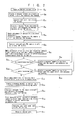
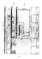
- FIG. 2 is a flowchart showing a procedure of the validation work in this embodiment, and shows measuring and operating procedures.
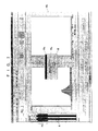
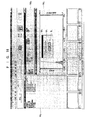
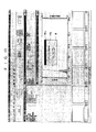
- FIG. 3 to FIG. 13 is a view showing one example of a window screen displayed on the display 3d pursuant to the progress of the validation work.
- step St1 shows one example of operation previously executed before the validation data D is read and the validation program P is executed. Namely, the operator presets validation standards.
- FIG. 3 is a view showing a window displayed on the display 3d of the personal computer 3 in the above step St1.
- W1 is a main window
- W2 is a display condition setup window.
- W3 is a validation setup window for setting validation judgment factors such that each standard diameter has what size ( ⁇ m) or an error in the size of diameter is applicable by what percents in plus and minus as an allowable range.
- the number of diameters set as the validation standard diameter is not limited to three. For example, only standard value and allowable range relative to median diameter may be set.
- the judgment standard of validation work set in the above manner is reflected in the validation data D. Namely, the operator can freely change the judgment standard of validation work. Likewise, the operator can freely change a kind of standard sample used in the validation work and physical information such a refractive index of the standard sample or the like.
- a PSL (Polystyrene latex) sphere having a diameter of 1 ⁇ m is used as the standard sample.
- various data such as a kind and allowable range of the standard sample may be predetermined as the judgment standard of validation work by a maker of the particle size distribution measuring apparatus.
- the validation program P reads the validation data D, and then, successively executes various processings based on the validation data D.
- step St2 shown in FIG. 2 the personal computer 3 displays a measuring window W4 on the display screen, and further, displays a message window W5 thereon. Moreover, in a message window W5, a message M1 "Please put dispersion medium in cell” is displayed, and thereafter, the same announce as the message M1 is converted into speech, and outputted from the speaker.
- the operator sets a cell, into which distilled water is put as a dispersion medium, in the measuring section 2, and thereafter, operates an OK button B displayed on the message window W5 (step St3).
- a method for operating the OK button B is as follows. For example, in the case of a keyboard, the OK button B is selected by a cursor key, and thereafter, a return key is pressed. Moreover, in the case of a mouse, the mouse is clicked in a state of bringing the cursor key to the OK button B. In order to simplify the description, the operation as described above is referred simply to "press the OK button".
- the personal computer 3 senses the completion of work when the operator presses the OK button B; however, the present invention is not limited to this embodiment. More specifically, the completion of work may be sensed by sensors attached to each part of the measuring section 2.
- the personal computer 3 reads the following procedure from the validation data D, and then, executes the procedure.
- the next procedure of validation work is blank measurement, and is a measuring procedure executable in the particle size distribution measuring apparatus 1 without requiring a work by the operator. Therefore, after waiting the operator's instruction, the personal computer 3 automatically controls each part of the measuring section 2, and then, executes the blank measurement.
- FIG. 5 shows a message window W6.
- a message M2 "execute blank measurement” is displayed, and the personal computer 3 is waiting for the operator to press the OK button B while making announce of the above message M2 (step St4).
- the personal computer makes an adjustment of optical axis according to the measuring procedure shown by the validation data D, and thereafter, executes a blank measurement.
- the personal computer 3 is controlled by the validation program P, and each part required for the blank measurement is automatically adjusted; therefore, the operator has no any operations.
- the personal computer 3 When the blank measurement is completed, the personal computer 3 again reads the validation data D, and then, executes the next validation work.
- the next validation work is a work procedure on which the operator puts the standard sample S in the cell. For this reason, the personal computer 3 displays a message window W7 as shown in FIG. 6.
- a message M3 for instructing the work procedure to the operator is displayed, and a speech of the same content as the message M3 is announced (step St5).
- the operator mixes a PSL sphere in the cell according to the above message M3, and then, inputs the completion of work by pressing the OK button B (step St8).
- the personal computer 3 reads the validation data D so as to execute the next validation work. More specifically, as shown in step St7, the personal computer 3 executes an adjustment of optical axis, and thereafter, measures a light transmittance in order to confirm whether or not a measuring object sample put by the operator has a transmittance within a range predetermined as a standard sample S for validation.
- step St8 a decision is made whether or not the light transmittance of the measuring object sample S is higher than the upper limit of predetermined transmittance.
- a message window W8 is displayed, and a message M4 "concentration is too thin. Please add sample thereto" is displayed on the window screen while announce by speech being outputted.
- a reference numeral 4 denotes a bar graph showing a light transmittance measured in the above step St8, and a reference numeral 4a denotes a predetermined range of the light transmittance.
- step St10 a decision is made whether or not the light transmittance of the measuring object sample S is lower than the lower limit of predetermined transmittance range 4a (step St10).
- a message window W10 is displayed, and a message M6 "Start measurement" is displayed on the window screen while announce by speech being outputted. Then, when the operator presses the OK button B, a measurement of particle size distribution is started (step St12).
- the personal computer 3 automatically executes the following various setting works of the particle size distribution measuring apparatus according to the measurement procedure recorded as the validation data D.
- the various setting works include an input of refractive index of the standard sample S and solvent required for measuring a particle size distribution, etc. Namely, the operator has no need of doing troublesome various setting works for the validation work. Moreover, it is possible to prevent a mistake which will be made in the case where the operator does the above various setting works by manual, and therefore, even an inexperienced operator can securely perform the validation work.
- the personal computer 3 displays the measured result on windows Wa to Wc according to the measurement procedure recorded as the validation data D, and thereafter, makes a decision whether or not the measured result is suitable. Namely, the personal computer 3 makes a decision whether or not the measured result of the particle size distribution measuring apparatus 1 is within an allowable error range.
- the personal computer 3 displays a message window W11 as shown in FIG. 10 in the case where the above measured result is within an allowable range, and displays a message M7 "Validation OK" on the window screen while outputting announce by speech.
- a message window W12 is displayed, and a message M8 "validation is not suitable” is displayed on the window screen while announce by speech being outputted (step St13).
- the personal computer 3 displays a message window W13 as shown in FIG. 12, and then, displays a message M9 "Is the result printed?" on the window screen while outputting announce by speech (step St14).
- the personal computer 3 prints inspection results such as measured result, validation standards, measuring person name, date and time, kind of measuring apparatus, operational parameters or the like via a printer (not shown) (step St15) Namely, the operator can determine whether the result should be printed when performing the validation work; therefore, the operator never forgets the records of validation work.
- step St16 when the operator presses a "no" button Bn, the personal computer 3 does no any works, and then, executes the next procedure (step St16).
- FIG. 13 shows an example of the next step St16.
- the personal computer 3 displays a window W14 for recording inspection results such as measured result, validation standards, measuring personal name, date and time, kind of measuring apparatus, operational parameters in a storage section 3m as a digital data.
- the window W14 has an input bar N, an input bar F, a list L, a save button Bs for executing a save, and a cancel button Bc for canceling a save. More specifically, the input bar N is used for setting a file name for adding a file bundling a saving data, and the input bar F is used for setting a folder saving the file, and further, the list L is used for displaying a file name list of the file already stored in the folder.
- step St16 the operator can input a folder and a file name by using the above input bars F and N (step St16).
- this embodiment has disclosed the case of printing the inspection result record on a paper and the case of storing it in a file as a digital data. Either of two disclosures may be carried out. Moreover, the inspection result record may be separately carried out by the operator.
- three parameter values are set with respect to one standard sample S as validation standards.
- the present invention is not limited to this embodiment.
- a geometrical mean particle diameter or the like may be set.
- the standard sample S to be measured is not limited to one kind.
- FIG. 14 is a view showing a particle size distribution measuring apparatus according to another embodiment of the present invention.
- a particle size distribution measuring apparatus 1' will be described below with reference to FIG. 14.
- like reference numerals are used to designate the same member as FIG. 1, and therefore, the details are omitted.
- a reference numeral 2' denotes a measuring section for measuring a particle size distribution of measuring object sample.
- the measuring section 2' is different from the measuring section 2 described in detail in FIG. 1 in that 2' has an automatic sample charger 5 for automatically charging a plurality of standard samples S1 to Sn according to the control by the personal computer 3.
- FIG. 15 is a flowchart showing a procedure of validation work performed according to the control of the particle size distribution measuring apparatus 1'.
- the same steps St1 to St17 as FIG. 2 have almost the same description as FIG. 2, and therefore, the details are omitted for simplification of description.
- step St3 standard samples S1 to Sn are set with respect to the automatic sample charger 5, and there is no need of making a message displayed in step St5 and charging a sample by the operator in step St6.
- step St1 for making a confirmation by the operator is added. More specifically, when measurement of one sample is completed, a message "next, measure another sample” is displayed on the screen, and then, announce by speech is made. In this case, when the operator presses the OK button, the personal computer 3 controls the automatic sample charger 5 so as to charge the next sample, and then, the procedures from step St4 is repeatedly made.
- step St18 when the procedure jumps from step St18 to step St4, a blank measurement is made every when the standard samples S1 to Sn are changed in succession, and thereby, a measurement accuracy is improved.
- the present invention is not limited to this embodiment.
- the procedure jumps from step St18 to step St7, and thereby, measurement may be made at a high speed.
- the operator when the operator performs a validation work, the operator can receive a suitable validation help. More specifically, by validation help function, it is possible to operate the particle size distribution measuring apparatus according to a work procedure given from a control unit in a predetermined order without making a mistake. Moreover, a measurement procedure controlled by only control unit is automatically made according to a sequence of the measurement procedure previously stored as a validation data. Therefore, the operator can perform the complicate validation work without referring to a manual, so that a load acting on the operator can be reduced to the minimum. In addition, the work procedure is executed by one step without making a mistake, so that the validation work can be accurately performed.
Landscapes
- Chemical & Material Sciences (AREA)
- Dispersion Chemistry (AREA)
- Physics & Mathematics (AREA)
- Health & Medical Sciences (AREA)
- Life Sciences & Earth Sciences (AREA)
- Analytical Chemistry (AREA)
- Biochemistry (AREA)
- General Health & Medical Sciences (AREA)
- General Physics & Mathematics (AREA)
- Immunology (AREA)
- Pathology (AREA)
- Investigating Or Analysing Materials By Optical Means (AREA)
Abstract
Description
- The present invention relates to a particle (grain) size measuring apparatus, which detects a diffraction/scattered light or dynamic light scattering by irradiating a laser beam to a particle group such as a dispersing powder sample or the like, and measures a particle size distribution of the particle group on the basis of a scattered light intensity signal or the like obtained by the detection.
- Conventionally, a particle size distribution measuring apparatus using light diffraction phenomenon or scattering phenomenon by a particle has calculated a particle size distribution of sample particle in the following manner. More specifically, the above apparatus measures intensity distribution of a diffraction light or a scattered light, that is, a relation between a diffraction angle or scattering angle and a light intensity, and then, carries out arithmetic processing based on a Frauunhofer diffraction theory or Mie scattering theory with respect to the measured result. In the above manner, the above apparatus has calculated the particle size distribution of sample particle. The above particle size distribution measuring apparatus has been used for research and development of raw materials in almost mining and industrial fields such as cement or ceramic industry, and in a new material field mainly using ceramics.
- For example, to give an example of the above apparatus, there is a particle size distribution measuring apparatus disclosed in Japanese Examined Patent publication No. 6-43950. FIG. 16 is a view schematically showing a construction of the particle size distribution measuring apparatus disclosed in this Publication. In FIG. 16, a
reference numeral 10 denotes a cell comprising a transparent container for receiving asample solution 11 dispersing a particle group of measuring object in a proper dispersion medium, and areference numeral 12 denotes a laser beam source provided on one side (backward side) of thecell 10. Aparallel laser beam 13 emitted from thelaser beam source 12 is enlarged by a beam expander (not shown), and then, is irradiated to thecell 10 in an enlarged state. - In FIG. 16, a
reference numeral 14 denotes a condenser lens provided on the other side (forward side) of thecell 10, and aring detector 15 is arranged at a focal position of thecondenser lens 14. Thering detector 15 is constructed in a manner that a plurality of photo sensors having mutually different radius and a ring or semi-ring light receiving plane is arrayed concentrically around an optical axis of thecondenser lens 14. Further, thering detector 15 receives a light scattered/diffracted at a relatively small angle of thelaser beam 13 diffracted or scattered by particles in thecell 10 for each scattering angle, and then, measures their light intensity. - Moreover, a wide angle scattered light
photo detector group 16 is provided at the vicinity of thecell 10. The wide angle scattered lightphoto detector group 16 individually detects a light scattered/diffracted at a relatively large angle of thelaser beam 13 diffracted/scattered by the particles in thecell 10 for each scattered light. Further, the wide angle scattered lightphoto detector group 16 is composed of a plurality ofphoto sensors 17 to 22 provided at an angle different from thecondenser lens 14 and thering detector 15. Thus, thephoto detector group 16 can detect a wide angle scattered light exceeding a predetermined angle by the particles in thecell 10 in accordance with each oriented angle. In thephoto detector group 16, thephoto sensors 17 to 20 detect a forward scattering light, thephoto sensor 21 detects a side scattering light, and thephoto sensor 22 detects a backscattering light. - A
reference numeral 23 denotes a pre-amplifier for amplifying an output of the photo sensors constituting thering detector 15, and areference numeral 24 denotes a pre-amplifier for amplifying each output of the forward scatteringlight photo sensors 17 to 20. Further, areference numeral 25 denotes a pre-amplifier for amplifying each output of the side scatteringlight photo sensor 21 and the backscatteringlight photo sensor 22. Areference numeral 26 denotes a multiplexer for successively capturing each output of thepre-amplifier groups 23 to 25 and transmitting it to anA-D converter 27, and areference numeral 28 denotes a computer which is used as an arithmetic processor for inputting an output from theA-D converter 27. Thecomputer 28 stores a program for processing each output converted into a digital signal (digital data relative to light intensity) of thering detector 15 and thephoto sensors 13 to 22 on the basis of a Frauunhofer diffraction theory or Mie scattering theory, and obtaining a particle size distribution in a particle group. - In the above particle size distribution measuring apparatus, in a state that the
sample solution 11 is received in thecell 10, when thelaser beam 13 is irradiated from thelaser beam source 12 to thesample cell 10, thelaser beam 13 is diffracted or scattered by the particles in thecell 10. Of the diffracted light or scattered light, a light having a relatively small scattering angle is imaged on thering detector 15 by thecondenser lens 14. In this case, the photo sensor arranged on the outer side receives a light having a larger scattering angle; on the other hand, the photo sensor arranged on the inner side receives a light having a smaller scattering angle. Therefore, a light intensity detected by the outer-side photo sensor means a quantity of particle having smaller particle diameter (particle size); on the other hand, a light intensity detected by the inner-side photo sensor means a quantity of sample particle having larger particle diameter. The light intensity detected by each of these photo sensors is converted into an analog electric signal, and further, is inputted to themultiplexer 26 via the pre-amplifier 23. - On the other hand, of the
laser beam 13 diffracted light or scattered by the particle, a light, which is not converged by thecondenser lens 14 and has a relatively large scattering angle, is detected by thephoto sensors 17 to 22, and then, its light intensity distribution is measured. In this case, the forward scatteringlight photo sensors 17 to 20, the side scatteringlight photo sensor 21 and the backscatteringlight photo sensor 22 successively detect a scattering light from a particle having a small particle size. The light intensity detected by each of thesephoto sensors 17 to 22 is converted into an analog electric signal, and further, is inputted to themultiplexer 26 via thepre-amplifier groups - The
multiplexer 26 captures a measurement data from thering detector 15 and thephoto sensors 17 to 22, that is, an analog electrical signal in a predetermined order. The analog electric signal captured by themultiplexer 26 is made into a serial signal, then, is converted by theA-D converter 27 into a digital signal in succession, and thereafter, is inputted to thecomputer 28. - Subsequently, the
computer 28 processes a light intensity data for each scattering angle obtained by each of thering detector 15, thephoto sensors 17 to 22 on the basis of a Frauunhofer diffraction theory or Mie scattering theory. - As described above, in the above particle size distribution measuring apparatus, a light intensity distribution of scattering light having a mainly larger particle size is measured by the
ring detector 15; on the other hand, a light intensity distribution of wide-angle scattering light having a mainly smaller particle size is measured by thephoto sensors 17 to 22. Further, the output of thesering detector 15 andphoto sensors 17 to 22 is processed by thecomputer 28. Therefore, it is possible to obtain a particle size distribution of particle group over a wide range from a relatively larger particle size to a micro particle size. - By the way, the particle size distribution measuring apparatus as described above requires periodically carrying out a validation work in order to make a decision whether or not its measuring accuracy is correctly made. In particular, in a pharmaceutical company, in the case where the above particle size distribution measuring apparatus is used for a quality control, the validation work must be correctly done at least one time per year.
- In order to correctly do the validation of the particle size distribution measuring apparatus, an operator must measure a predetermined standard sample according to a determined procedure. For this reason, in the conventional particle size distribution measuring apparatus, the operator prepares a validation manual recording procedures of the above validation work, and then, must carry out the validation work according to the determined validation procedures.
- However, a measuring technique using the above particle size distribution measuring apparatus is complicate, and therefore, it is difficult for an inexperienced operator to memorize and operate all of working procedures. For this reason, in the case where the inexperienced operator operates the above apparatus, the operator must operate a control unit while referring to a user manual. In fact, when the inexperienced operator makes the above operation while referring to the user manual, the operator is easy to make a mistake of the sequence of work, and does not notice the mistake. Therefore, validation is incorrectly carried out; for this reason, the numerical value has no reliability.
- In such a case, measurement must be retried. However, in order to again make a measurement, the following works are required. More specifically, dispersion medium and standard sample in a sample supply apparatus are discharged, and the sample supply apparatus is washed, and thereafter, the dispersion medium and standard sample are charged in the supply apparatus. Time and labor are much spent for doing the above work, and in the case where the standard sample is valuable, there is a possibility that many standard samples are wasted.
- After the validation work is completed, the operator makes a report based on the measurement result, and must store the report; however, there is the case where the operator forgets this work. For this reason, there is a problem that no record is stored in spite of carrying out validation work.
- In addition, the above scattering type particle size distribution measuring apparatus uses precision optical components, laser beam source, a motor and the like; for this reason, there is a possibility that an accident happens in the case where a user disassemble the apparatus in error, or makes a handling mistake. In order to prevent such an accident, conventionally, caution matters has been prescribed in a manual or the like, or a label describing handling caution matters has been stuck onto the apparatus main body. However, the aforesaid accident happens due to user's careless mistake and an erroneous operation by an inexperienced operator; for this reason, there is a possibility that the number of many processes is required in a maker side or user side.
- The present invention has been made in view of the aforesaid problems in the related art. It is, therefore, an object of the present invention to provide a particle size distribution measuring apparatus, which has a function of informing an operator of a procedure of validation work of the particle size distribution measuring apparatus, and thereby, can prevent a generation of mistake in a complicate validation work.
- In order to achieve the above object, the present invention provides a particle size distribution measuring apparatus comprising a storage medium for storing validation procedure data being used to carry out validation procedures for the particle size distribution measuring apparatus, and a control unit for controlling the validation procedures by successively reading validation procedure data from the storage medium and controlling the particle size distribution measuring apparatus according to the read out validation procedure data to execute the respective validation procedure, wherein the control unit carries out a validation procedure itself, if no operation by an operator in the validation procedure is required, and provides help to the operator when an operation by the operator is required in a validation procedure.
- Therefore, when carrying out the validation work during the validation procedures, the operator uses a validation help function provided by the control unit, and thereby, can operate the particle size distribution measuring apparatus according to the help information provided by the control unit which preferably comprises the teaching of work procedures given from the control unit in the predetermined order without making a mistake. Moreover, the measuring procedure controlled by only control unit is automatically carried out, by which the control unit controls the particle size distribution measuring apparatus according to an operation sequence previously stored as a validation data.
- The measuring procedure automatically carried out by the control unit includes a procedure for setting a setup value of measuring object sample such as a refractive index of standard sample used for the validation work. Therefore, the operator has no need of carrying out trouble some various setup operations for the validation work.
- Accordingly, the operator can perform the complicate validation work without referring to a manual, and thereby, it is possible to reduce a load acting to the operator to the minimum, and to successively carry out the validation work made by the operator during the validation procedures step by step without making a mistake. This serves to more accurately perform the validation work.
- In the case where the control unit has a warning function of pointing out the operator's mistake in the validation procedures to the operator, and teaching a validation work according to a correct validation procedure, when the operator makes an erroneous operation, a warning is given from the control unit. Therefore, the validation work is accurately performed, so that the measured result having a high reliability can be obtained.
- The following matter is considered as the aforesaid mistake in the validation procedures; more specifically, the operator charges a standard sample unsuitable for the measurement condition. For example, it is considered that concentration and temperature of the charged sample are without a range of measurement condition predetermined as a standard sample. In this case, the concentration of sample is previously measured by a light transmittance, and then, in the case where the measured result is different from the sample concentration condition, the control unit can give an instruction to adjust the concentration of sample to the operator. Moreover, the control unit may have a warning function which confirms the measurement condition during measurement of particle size distribution, and gives an instruction to retry the measurement in the case where the measurement condition is without a range of predetermined value.
- In the case where the control unit has a speech (voice) output section for outputting an instruction to the operator by a speech signal, an operating instruction is given by a speech; therefore, the operator can readily perform the validation procedures according to the speech without giving attention to reading a manual and the like.
- In the case where the control unit has a monitor screen for displaying an instruction to the operator, the operator can obtain instructions for validation work via a display screen; therefore, it is possible to readily perform the validation work.
- Moreover, in the case where the particle size distribution measuring apparatus of the present invention has an automatic charger for successively charging a standard sample used for the validation work into the above particle size distribution measuring apparatus, it is possible to reduce a work done by the operator to the minimum, and further, to easily handle the above apparatus. In this case, preferably, the control unit has a function of continuously measuring a plurality of standard samples.
- The control unit has a judgment function of comparing an inspection result obtained from the validation work with a performance standard of the particle size distribution measuring apparatus, and making a judgment whether or not the comparative result is within the performance standard range. In this case, the operator has no need of collating the comparative result with a standard chart of the particle size distribution measuring apparatus, and making a judgment whether or not an error is within the performance standard range.
- In the case where the control unit has a recording function of recording the inspection result obtained by the validation work, the inspection result is automatically stored after the validation work is performed. Even in the case where the operator forgets the output of inspection result, it is possible to prepare a report using records of the inspection result automatically stored.
- Therefore, there is no case where the record is lost in spite of carrying out the validation work. In this case, the record of the inspection result may be a result data stored in the storage medium, or may be an inspection result report outputted by a printer or the like.
-
- FIG. 1
- is a view schematically showing a construction of a particle size distribution measuring apparatus according to one embodiment of the present invention;
- FIG. 2
- is a view to explain an operation of validation help function of the above embodiment;
- FIG. 3
- is a view showing a display window on a screen when measuring a standard sample using the validation help function of the particle size distribution measuring apparatus;
- FIG. 4
- is a view showing another display window on the screen;
- FIG. 5
- is a view showing another display window on the screen;
- FIG. 6
- is a view showing another display window on the screen;
- FIG. 7
- is a view showing another display window on the screen;
- FIG. 8
- is a view showing another display window on the screen;
- FIG. 9
- is a view showing another display window on the screen;
- FIG. 10
- is a view showing another display window on the screen;
- FIG. 11
- is a view showing another display window on the screen;
- FIG. 12
- is a view showing another display window on the screen;
- FIG. 13
- is a view showing another display window on the screen;
- FIG. 14
- is a view showing a particle size distribution measuring apparatus according to another embodiment;
- FIG. 15
- is a view to explain an operation of validation help function of the above embodiment; and
- FIG. 16
- is a view to explain the measuring principle of a conventional particle size distribution measuring apparatus.
- One embodiment of the present invention will be described below with reference to the accompanying drawings.
- In FIG. 1, a particle size distribution measuring apparatus 1 of this embodiment has a
measuring section 2 for measuring a particle size distribution of a measuring object sample S, and acontrol unit 3 connected to themeasuring section 2. In themeasuring section 2, a laser beam is irradiated to the measuring object sample S charged from a charging hole so as to detect a scattered light by particles in the measuring object sample S, and then, the scattered light is analyzed, and thereby, its particle size distribution is measured. - In this embodiment, the
control unit 3 is an information processing unit (hereinafter, referred to personal computer 3), which is connected to themeasuring section 2 via a communication cable C. Thecontrol unit 3 has adisplay 3d (i.e., monitor screen) and akeyboard 3k. However, in the present invention, the construction of thecontrol unit 3 is not limited to this embodiment. For example, thecontrol unit 3 may be a microcomputer provided in themeasuring section 2. - The aforesaid
personal computer 3 has aCPU 3c, a storage (memory)section 3m such as a RAM, a ROM, a hard disk or the like, and an input-output interface 3i. Thestorage section 3m previously stores a control program Pc, and thepersonal computer 3 controls the measuringsection 2 by executing the control program Pc. More specifically, thepersonal computer 3 executes various arithmetic processings on the basis of a data inputted from the input-output interface 3i, and outputs the processing (output) result via the input-output interface 3i. - Moreover, the input-
output interface 3i is connected with the communication cable C so that a signal from sensors (not shown) incorporated into each part of the measuringsection 2 can be transmitted to the personal computer main body via the communication cable C. - The
storage section 3m stores a validation program P and a validation data D decoded by the validation program ,in addition to the above control program Pc. More specifically, thepersonal computer 3 has a validation help function by the control program Pc, the validation program P and the validation data D. - In this embodiment, regardless of the validation work, the validation program P is executable by reading a control data (including the above validation data D) recorded by a simple language for controlling the
measuring section 2, and thereby, the validation program P has a general-purpose characteristic. - Further, the validation program P automatically and successively carries out a procedure executable in the particle size distribution measuring apparatus 1, in the procedures of validation work recorded as the validation data D. Meanwhile, regarding a procedure requiring an operation by the operator, the validation program P is programmed so as to give a work instruction relative to the procedure to the operator. As a result, the operator merely carries out a necessary and minimum operation, so that the validation work can be simplified.
- The work instruction to the operator is outputted by a message on
display screen 3d and a voice announce. More specifically, in the case of carrying out a validation work, the operator has no need of reading a manual describing a working procedure for the validation, and can perform the validation work according to a message displayed on thedisplay screen 3d or announced speech; therefore, the operator is able to have a concentration on the validation work. - The validation data D includes at least one of announce by speech and a message displayed on the display screen. For example, in the case of carrying out announce by speech, the
personal computer 3 has aconverter 3t for converting a digital data stored as validation data D into a speech (aural) signal, and aspeaker 3s which is a speech output section. - The validation program P is programmed in a manner that a work situation of the operator is detected and grasped by sensors incorporated into each part of the measuring
section 2. In the case where the operator makes a mistake in the work procedure, the validation program P is programmed in a manner of giving a warning to the operator, and giving an instruction for carrying out the validation work according a correct work procedure to the same. - The following matter is considered as the above mistake in the work procedure; more specifically, the measuring object sample S charged into the measuring
section 2 by the operator is without a range of concentration usable as a standard sample. In this case, it is possible to use a sensor for measuring a light transmittance of the measuring object sample S. Moreover, in the case where the inexperienced operator makes a mistake of handling themeasuring section 2 by his careless or erroneous operation, a warning can be given to the operator. More specifically, when the operator opens a cover of the apparatus, which should not be opened during measurement work, the following announce or message is made or displayed; for example, "Please close the cover. Please do not see laser beam source in the apparatus." - FIG. 2 is a flowchart showing a procedure of the validation work in this embodiment, and shows measuring and operating procedures. FIG. 3 to FIG. 13 is a view showing one example of a window screen displayed on the
display 3d pursuant to the progress of the validation work. - In FIG. 2, step St1 shows one example of operation previously executed before the validation data D is read and the validation program P is executed. Namely, the operator presets validation standards.
- FIG. 3 is a view showing a window displayed on the
display 3d of thepersonal computer 3 in the above step St1. - In FIG. 3, W1 is a main window, and W2 is a display condition setup window. When seeing the display condition setup window W2, in this embodiment, it is possible to input standard values relative to three kinds of diameters (median diameter, 10% diameter, 90% diameter) with respect to one standard sample. W3 is a validation setup window for setting validation judgment factors such that each standard diameter has what size (µm) or an error in the size of diameter is applicable by what percents in plus and minus as an allowable range.
- More specifically, in this embodiment, three kinds of standard diameters are set with respect to one standard sample, and then, in each diameter, a judgment is made whether or not the measured value is within an allowable error; therefore, it is possible to perform a more detailed validation work. In the present invention, the number of diameters set as the validation standard diameter is not limited to three. For example, only standard value and allowable range relative to median diameter may be set.
- The judgment standard of validation work set in the above manner is reflected in the validation data D. Namely, the operator can freely change the judgment standard of validation work. Likewise, the operator can freely change a kind of standard sample used in the validation work and physical information such a refractive index of the standard sample or the like.
- In the following embodiment, a PSL (Polystyrene latex) sphere having a diameter of 1 µm is used as the standard sample. Moreover, various data such as a kind and allowable range of the standard sample may be predetermined as the judgment standard of validation work by a maker of the particle size distribution measuring apparatus.
- Next, when the validation program P starts up, the validation program P reads the validation data D, and then, successively executes various processings based on the validation data D.
- In step St2 shown in FIG. 2, the
personal computer 3 displays a measuring window W4 on the display screen, and further, displays a message window W5 thereon. Moreover, in a message window W5, a message M1 "Please put dispersion medium in cell" is displayed, and thereafter, the same announce as the message M1 is converted into speech, and outputted from the speaker. - Subsequently, the operator sets a cell, into which distilled water is put as a dispersion medium, in the
measuring section 2, and thereafter, operates an OK button B displayed on the message window W5 (step St3). In this case, a method for operating the OK button B is as follows. For example, in the case of a keyboard, the OK button B is selected by a cursor key, and thereafter, a return key is pressed. Moreover, in the case of a mouse, the mouse is clicked in a state of bringing the cursor key to the OK button B. In order to simplify the description, the operation as described above is referred simply to "press the OK button". - In this embodiment, the
personal computer 3 senses the completion of work when the operator presses the OK button B; however, the present invention is not limited to this embodiment. More specifically, the completion of work may be sensed by sensors attached to each part of the measuringsection 2. - Next, the
personal computer 3 reads the following procedure from the validation data D, and then, executes the procedure. The next procedure of validation work is blank measurement, and is a measuring procedure executable in the particle size distribution measuring apparatus 1 without requiring a work by the operator. Therefore, after waiting the operator's instruction, thepersonal computer 3 automatically controls each part of the measuringsection 2, and then, executes the blank measurement. - FIG. 5 shows a message window W6. In this message window W6, a message M2 "execute blank measurement" is displayed, and the
personal computer 3 is waiting for the operator to press the OK button B while making announce of the above message M2 (step St4). - Subsequently, when the OK button B is pressed, the personal computer makes an adjustment of optical axis according to the measuring procedure shown by the validation data D, and thereafter, executes a blank measurement. In this case, the
personal computer 3 is controlled by the validation program P, and each part required for the blank measurement is automatically adjusted; therefore, the operator has no any operations. - When the blank measurement is completed, the
personal computer 3 again reads the validation data D, and then, executes the next validation work. The next validation work is a work procedure on which the operator puts the standard sample S in the cell. For this reason, thepersonal computer 3 displays a message window W7 as shown in FIG. 6. In the message window W7, a message M3 for instructing the work procedure to the operator is displayed, and a speech of the same content as the message M3 is announced (step St5). - Subsequently, the operator mixes a PSL sphere in the cell according to the above message M3, and then, inputs the completion of work by pressing the OK button B (step St8).
- Then, the
personal computer 3 reads the validation data D so as to execute the next validation work. More specifically, as shown in step St7, thepersonal computer 3 executes an adjustment of optical axis, and thereafter, measures a light transmittance in order to confirm whether or not a measuring object sample put by the operator has a transmittance within a range predetermined as a standard sample S for validation. - Namely, a decision is made whether or not the light transmittance of the measuring object sample S is higher than the upper limit of predetermined transmittance (step St8).
- At that time, in the case where the transmittance is too high, as shown in FIG. 7, a message window W8 is displayed, and a message M4 "concentration is too thin. Please add sample thereto" is displayed on the window screen while announce by speech being outputted. In FIG. 8 and FIG. 9 described later, a
reference numeral 4 denotes a bar graph showing a light transmittance measured in the above step St8, and areference numeral 4a denotes a predetermined range of the light transmittance. When the operator presses the OK button B, the validation work is returned to step St6, and then, measurement for the light transmittance can be retried (step St9). - On the other hand, in the case where the
light transmittance 4 of the measuring object sample S is not higher than the upper limit of thepredetermined transmittance range 4a, conversely, a decision is made whether or not the light transmittance of the measuring object sample S is lower than the lower limit ofpredetermined transmittance range 4a (step St10). - In the case where the
light transmittance 4 is too low, as shown in FIG. 8, a message window W9 is displayed, and a message M5 "concentration is too strong. Please make sample thin" is displayed on the window screen while announce by speech being outputted. When the operator presses the OK button B, the validation work is returned to step St6, and then, measurement for the light transmittance can be retried (step St1 1). - In the above manner, in the case where the
light transmittance 4 is set within thepredetermined range 4a, as shown in FIG. 9, a message window W10 is displayed, and a message M6 "Start measurement" is displayed on the window screen while announce by speech being outputted. Then, when the operator presses the OK button B, a measurement of particle size distribution is started (step St12). - In this case, the
personal computer 3 automatically executes the following various setting works of the particle size distribution measuring apparatus according to the measurement procedure recorded as the validation data D. The various setting works include an input of refractive index of the standard sample S and solvent required for measuring a particle size distribution, etc. Namely, the operator has no need of doing troublesome various setting works for the validation work. Moreover, it is possible to prevent a mistake which will be made in the case where the operator does the above various setting works by manual, and therefore, even an inexperienced operator can securely perform the validation work. - Subsequently, when the particle size distribution measurement is completed, the
personal computer 3 displays the measured result on windows Wa to Wc according to the measurement procedure recorded as the validation data D, and thereafter, makes a decision whether or not the measured result is suitable. Namely, thepersonal computer 3 makes a decision whether or not the measured result of the particle size distribution measuring apparatus 1 is within an allowable error range. - Then, the
personal computer 3 displays a message window W11 as shown in FIG. 10 in the case where the above measured result is within an allowable range, and displays a message M7 "Validation OK" on the window screen while outputting announce by speech. On the other hand, in the case where the above measured result is outside the allowable range, as shown in FIG. 11, a message window W12 is displayed, and a message M8 "validation is not suitable" is displayed on the window screen while announce by speech being outputted (step St13). - In any cases, when the operator presses the OK button B shown in FIG. 10 and FIG. 11, the
personal computer 3 displays a message window W13 as shown in FIG. 12, and then, displays a message M9 "Is the result printed?" on the window screen while outputting announce by speech (step St14). - When the operator presses a "yes" button By, the
personal computer 3 prints inspection results such as measured result, validation standards, measuring person name, date and time, kind of measuring apparatus, operational parameters or the like via a printer (not shown) (step St15) Namely, the operator can determine whether the result should be printed when performing the validation work; therefore, the operator never forgets the records of validation work. - On the other hand, in the window W13 shown in FIG. 12, when the operator presses a "no" button Bn, the
personal computer 3 does no any works, and then, executes the next procedure (step St16). - FIG. 13 shows an example of the next step St16. In this embodiment, the
personal computer 3 displays a window W14 for recording inspection results such as measured result, validation standards, measuring personal name, date and time, kind of measuring apparatus, operational parameters in astorage section 3m as a digital data. The window W14 has an input bar N, an input bar F, a list L, a save button Bs for executing a save, and a cancel button Bc for canceling a save. More specifically, the input bar N is used for setting a file name for adding a file bundling a saving data, and the input bar F is used for setting a folder saving the file, and further, the list L is used for displaying a file name list of the file already stored in the folder. - Therefore, the operator can input a folder and a file name by using the above input bars F and N (step St16). The operator presses the save button Bs, and thereby, it is possible to readily save the inspection result (step St17).
- On the other hand, when the operator presses the cancel button Bc, the save of the inspection result is cancelled, and the validation work ends.
- The aforesaid embodiment is merely one embodiment of the present invention, and therefore, the present invention is not limited to this embodiment. More specifically, in the above embodiment, respective contents of the messages M1 to M9 displayed on each of the windows W5 to W13 may be announced by speech (voice), and thereby, the operator can extremely readily obtain validation help from the
personal computer 3. The present invention is not limited to this modification and the message may be made by either of display on thedisplay screen 3d or announce by speech. - Likewise, this embodiment has disclosed the case of printing the inspection result record on a paper and the case of storing it in a file as a digital data. Either of two disclosures may be carried out. Moreover, the inspection result record may be separately carried out by the operator.
- In the above embodiment, as shown in the window W2 of FIG. 3, three parameter values (median diameter, 10% diameter, 90% diameter) are set with respect to one standard sample S as validation standards. The present invention is not limited to this embodiment. For example, a geometrical mean particle diameter or the like may be set.
- Further, the standard sample S to be measured is not limited to one kind.
- FIG. 14 is a view showing a particle size distribution measuring apparatus according to another embodiment of the present invention. A particle size distribution measuring apparatus 1' will be described below with reference to FIG. 14. In the particle size distribution measuring apparatus 1', like reference numerals are used to designate the same member as FIG. 1, and therefore, the details are omitted.
- In this embodiment, a reference numeral 2' denotes a measuring section for measuring a particle size distribution of measuring object sample. The measuring section 2' is different from the measuring
section 2 described in detail in FIG. 1 in that 2' has anautomatic sample charger 5 for automatically charging a plurality of standard samples S1 to Sn according to the control by thepersonal computer 3. - FIG. 15 is a flowchart showing a procedure of validation work performed according to the control of the particle size distribution measuring apparatus 1'. In FIG. 15, the same steps St1 to St17 as FIG. 2 have almost the same description as FIG. 2, and therefore, the details are omitted for simplification of description.
- In each procedure shown in FIG. 15, the point different from the description of FIG. 2 is as follows. More specifically, in step St3, standard samples S1 to Sn are set with respect to the
automatic sample charger 5, and there is no need of making a message displayed in step St5 and charging a sample by the operator in step St6. - Moreover, in this embodiment, the following step St1 for making a confirmation by the operator is added. More specifically, when measurement of one sample is completed, a message "next, measure another sample" is displayed on the screen, and then, announce by speech is made. In this case, when the operator presses the OK button, the
personal computer 3 controls theautomatic sample charger 5 so as to charge the next sample, and then, the procedures from step St4 is repeatedly made. - In this embodiment, when the procedure jumps from step St18 to step St4, a blank measurement is made every when the standard samples S1 to Sn are changed in succession, and thereby, a measurement accuracy is improved. The present invention is not limited to this embodiment. For example, the procedure jumps from step St18 to step St7, and thereby, measurement may be made at a high speed.
- As is evident from the above description, by using the particle size distribution measuring apparatus of the present invention, when the operator performs a validation work, the operator can receive a suitable validation help. More specifically, by validation help function, it is possible to operate the particle size distribution measuring apparatus according to a work procedure given from a control unit in a predetermined order without making a mistake. Moreover, a measurement procedure controlled by only control unit is automatically made according to a sequence of the measurement procedure previously stored as a validation data. Therefore, the operator can perform the complicate validation work without referring to a manual, so that a load acting on the operator can be reduced to the minimum. In addition, the work procedure is executed by one step without making a mistake, so that the validation work can be accurately performed.
Claims (7)
- A particle size distribution measuring apparatus,
characterized by:a storage medium for storing validation procedure data being used to carry out validation procedures for the particle size distribution measuring apparatus, anda control unit for controlling the validation procedures by successively reading validation procedure data from the storage medium and controlling the particle size distribution measuring apparatus according to the read out validation procedure data to execute the respective validation procedure, wherein the control unit carries out a validation procedure itself, if no operation by an operator in the validation procedure is required, and provides help to the operator when an operation by the operator is required in a validation procedure. - The particle size distribution measuring apparatus according to claim 1, wherein the control unit has a warning function of pointing out the operator's mistake in an operator's operation to the operator, and teaching the operator how to correctly execute the corresponding operation.
- The particle size distribution measuring apparatus according to claim 1 or 2, wherein the control unit has a speech output section for outputting an instruction to the operator by a speech signal.
- The particle size distribution measuring apparatus according to anyone of the claims 1 to 3, wherein the control unit has a monitor screen for displaying an instruction to the operator.
- The particle size distribution measuring apparatus according to anyone of the claims 1 to 4, wherein an automatic charger for successively charging a standard sample used for the validation procedures into the particle size distribution measuring apparatus is equipped.
- The particle size distribution measuring apparatus according to anyone of the claims 1 to 5, wherein the control unit has a judgment function of comparing an inspection result obtained from the validation procedures with a performance standard of the particle size distribution measuring apparatus, and making a judgment whether or not the comparative result is within the performance standard range.
- The particle size distribution measuring apparatus according to anyone of the claims 1 to 6, wherein the control unit has a recording function of recording the inspection result obtained by the validation procedures.
Applications Claiming Priority (2)
| Application Number | Priority Date | Filing Date | Title |
|---|---|---|---|
| JP2000142963 | 2000-05-16 | ||
| JP2000142963A JP3398121B2 (en) | 2000-05-16 | 2000-05-16 | Particle size distribution analyzer |
Publications (1)
| Publication Number | Publication Date |
|---|---|
| EP1156319A1 true EP1156319A1 (en) | 2001-11-21 |
Family
ID=18649842
Family Applications (1)
| Application Number | Title | Priority Date | Filing Date |
|---|---|---|---|
| EP01111427A Withdrawn EP1156319A1 (en) | 2000-05-16 | 2001-05-10 | Particle size distribution measuring apparatus |
Country Status (3)
| Country | Link |
|---|---|
| US (1) | US6741350B2 (en) |
| EP (1) | EP1156319A1 (en) |
| JP (1) | JP3398121B2 (en) |
Cited By (2)
| Publication number | Priority date | Publication date | Assignee | Title |
|---|---|---|---|---|
| WO2005026699A1 (en) * | 2003-09-12 | 2005-03-24 | Sacmi Cooperativa Meccanici Imola Societa' Cooperativa | Method for continuously controlling the particle size distribution of powders used in the ceramics industry, and plant for its implementation |
| EP1621865A1 (en) * | 2004-07-26 | 2006-02-01 | Horiba, Ltd. | Particle size distribution analyzer |
Families Citing this family (20)
| Publication number | Priority date | Publication date | Assignee | Title |
|---|---|---|---|---|
| JP3814190B2 (en) * | 2001-11-09 | 2006-08-23 | 株式会社堀場製作所 | Particle size distribution measuring device |
| US20050031188A1 (en) * | 2003-08-10 | 2005-02-10 | Luu Victor Van | Systems and methods for characterizing a sample |
| JP4578205B2 (en) * | 2004-08-31 | 2010-11-10 | 株式会社堀場製作所 | Particle size distribution measuring device |
| JP4588390B2 (en) * | 2004-08-31 | 2010-12-01 | 株式会社堀場製作所 | Particle size distribution measuring device |
| JP4454555B2 (en) * | 2005-08-29 | 2010-04-21 | 株式会社堀場製作所 | Particle size distribution measuring device |
| JP5272641B2 (en) * | 2008-10-21 | 2013-08-28 | 三菱瓦斯化学株式会社 | Method for evaluating graphite oxide particle-containing liquid, method for producing graphite oxide particle-containing liquid using the same, and method for producing conductor |
| JP5913787B2 (en) * | 2010-02-26 | 2016-04-27 | 株式会社堀場製作所 | Particle size distribution measuring device |
| JP2017009466A (en) * | 2015-06-23 | 2017-01-12 | 富士電機株式会社 | Method for calibrating particle composite analysis device, and particle composite analysis device |
| JP6441195B2 (en) * | 2015-09-14 | 2018-12-19 | 東芝メモリ株式会社 | Particle detector |
| US10048366B1 (en) * | 2018-01-30 | 2018-08-14 | Oculii Corp | Systems and methods for virtual aperature radar tracking |
| WO2021034561A1 (en) | 2019-08-16 | 2021-02-25 | Nutrition & Biosciences USA 4, Inc. | Flour- and meal-based food products comprising insoluble alpha-1,3-glucan |
| WO2021092228A1 (en) | 2019-11-06 | 2021-05-14 | Nutrition & Biosciences USA 4, Inc. | Highly crystalline alpha-1,3-glucan |
| WO2021158543A1 (en) | 2020-02-04 | 2021-08-12 | Nutrition & Biosciences USA 4, Inc. | Aqueous dispersions of insoluble alpha-glucan comprising alpha-1,3 glycosidic linkages |
| WO2022235655A1 (en) | 2021-05-04 | 2022-11-10 | Nutrition & Biosciences USA 4, Inc. | Compositions comprising insoluble alpha-glucan |
| EP4334364A1 (en) | 2021-05-04 | 2024-03-13 | Nutrition & Biosciences USA 4, Inc. | Compositions comprising oxidized insoluble alpha-glucan |
| WO2023081341A1 (en) | 2021-11-05 | 2023-05-11 | Nutrition & Biosciences USA 4, Inc. | Compositions comprising one cationic alpha- 1,6-glucan derivative and one alpha- 1,3-glucan |
| EP4463519A1 (en) | 2022-01-12 | 2024-11-20 | Nutrition & Biosciences USA 4, Inc. | Coating compositions comprising rubber and insoluble alpha-glucan |
| US20250339361A1 (en) | 2022-11-02 | 2025-11-06 | Nutrition & Biosciences USA 4, Inc. | Compositions comprising xanthan gum and crystalline alpha-1,3-glucan |
| CN121398902A (en) | 2023-06-30 | 2026-01-23 | 营养与生物科学美国第四公司 | Porous alpha-1, 3-glucan compositions |
| WO2026024663A1 (en) | 2024-07-24 | 2026-01-29 | Nutrition & Biosciences USA 4, Inc. | Compositions comprising alpha-glucan with alpha-1,3 glycosidic linkages |
Citations (3)
| Publication number | Priority date | Publication date | Assignee | Title |
|---|---|---|---|---|
| JPH03115950A (en) * | 1989-09-29 | 1991-05-16 | Shimadzu Corp | Particle size distribution measuring device |
| EP0571053A2 (en) * | 1985-11-04 | 1993-11-24 | Cell Analysis Systems, Inc. | Analysis method and apparatus for biological specimens |
| US5380663A (en) * | 1984-12-24 | 1995-01-10 | Caribbean Microparticles Corporation | Automated system for performance analysis and fluorescence quantitation of samples |
Family Cites Families (15)
| Publication number | Priority date | Publication date | Assignee | Title |
|---|---|---|---|---|
| US5408307A (en) * | 1988-07-11 | 1995-04-18 | Omron Tateisi Electronics Co. | Cell analyzer |
| US5033095A (en) * | 1988-09-30 | 1991-07-16 | Marcantonio Jeffrey J | Scanning image analyzer for accumulating quantifiable contaminants of webs |
| JPH06249857A (en) | 1993-02-26 | 1994-09-09 | Hitachi Ltd | Automatic analyzer |
| US5576827A (en) * | 1994-04-15 | 1996-11-19 | Micromeritics Instrument Corporation | Apparatus and method for determining the size distribution of particles by light scattering |
| JP3213211B2 (en) * | 1995-07-20 | 2001-10-02 | ホーチキ株式会社 | Photoelectric smoke detector |
| US5922976A (en) * | 1995-10-12 | 1999-07-13 | California Institute Of Technology | Method of measuring aerosol particles using automated mobility-classified aerosol detector |
| JP3827731B2 (en) * | 1995-10-25 | 2006-09-27 | フロイント産業株式会社 | Particle measuring apparatus for powder processing apparatus and particle measuring method using the same |
| US5966677A (en) * | 1997-02-28 | 1999-10-12 | Fiekowsky; Peter J. | High accuracy particle dimension measurement system |
| GB2326229A (en) * | 1997-06-13 | 1998-12-16 | Robert Jeffrey Geddes Carr | Detecting and analysing submicron particles |
| US5867273A (en) * | 1997-07-07 | 1999-02-02 | General Electric Company | Automated measurements and visualization system |
| US6346983B1 (en) * | 1998-01-29 | 2002-02-12 | Aleksandr L. Yufa | Methods and wireless communicating particle counting and measuring apparatus |
| US6246474B1 (en) * | 1998-04-29 | 2001-06-12 | Particle Measuring Systems, Inc. | Method and apparatus for measurement of particle size distribution in substantially opaque slurries |
| JP3086873B2 (en) * | 1998-08-04 | 2000-09-11 | 工業技術院長 | Particle size distribution measuring method and device |
| JP3393817B2 (en) * | 1998-10-16 | 2003-04-07 | 株式会社堀場製作所 | Particle size distribution measuring device |
| US6236458B1 (en) * | 1998-11-20 | 2001-05-22 | Horiba, Ltd. | Particle size distribution measuring apparatus, including an array detector and method of manufacturing the array detector |
-
2000
- 2000-05-16 JP JP2000142963A patent/JP3398121B2/en not_active Expired - Fee Related
-
2001
- 2001-05-10 EP EP01111427A patent/EP1156319A1/en not_active Withdrawn
- 2001-05-16 US US09/858,389 patent/US6741350B2/en not_active Expired - Fee Related
Patent Citations (3)
| Publication number | Priority date | Publication date | Assignee | Title |
|---|---|---|---|---|
| US5380663A (en) * | 1984-12-24 | 1995-01-10 | Caribbean Microparticles Corporation | Automated system for performance analysis and fluorescence quantitation of samples |
| EP0571053A2 (en) * | 1985-11-04 | 1993-11-24 | Cell Analysis Systems, Inc. | Analysis method and apparatus for biological specimens |
| JPH03115950A (en) * | 1989-09-29 | 1991-05-16 | Shimadzu Corp | Particle size distribution measuring device |
Non-Patent Citations (2)
| Title |
|---|
| LOHN A ET AL: "A knowledge-based system for real-time validation of calibrations and measurements", CHEMOMETRICS AND INTELLIGEMT LABORATORY SYSTEMS, ELSEVIER SCIENCE PUBLISHERS, AMSTERDAM, NL, vol. 46, no. 1, 15 February 1999 (1999-02-15), pages 57 - 66, XP004154894, ISSN: 0169-7439 * |
| PATENT ABSTRACTS OF JAPAN vol. 015, no. 320 (P - 1238) 15 August 1991 (1991-08-15) * |
Cited By (3)
| Publication number | Priority date | Publication date | Assignee | Title |
|---|---|---|---|---|
| WO2005026699A1 (en) * | 2003-09-12 | 2005-03-24 | Sacmi Cooperativa Meccanici Imola Societa' Cooperativa | Method for continuously controlling the particle size distribution of powders used in the ceramics industry, and plant for its implementation |
| EP1621865A1 (en) * | 2004-07-26 | 2006-02-01 | Horiba, Ltd. | Particle size distribution analyzer |
| US7180592B2 (en) | 2004-07-26 | 2007-02-20 | Horiba, Ltd. | Particle size distribution analyzer |
Also Published As
| Publication number | Publication date |
|---|---|
| JP3398121B2 (en) | 2003-04-21 |
| US20010048366A1 (en) | 2001-12-06 |
| US6741350B2 (en) | 2004-05-25 |
| JP2001324441A (en) | 2001-11-22 |
Similar Documents
| Publication | Publication Date | Title |
|---|---|---|
| US6741350B2 (en) | Particle size distribution measuring apparatus with validation and instruction modes | |
| JP5301232B2 (en) | Blood cell image display device, sample analysis system, blood cell image display method, and computer program | |
| EP2037281B1 (en) | Sample analyzer | |
| EP2618158A2 (en) | Sample analyzer and sample analyzing method | |
| CN110967512B (en) | Measuring device and precision management method | |
| JP2010014405A (en) | Sample analyzer, particle distribution chart displaying method and computer program | |
| US20090244068A1 (en) | Sample analyzer and computer program product | |
| JP2011039046A (en) | Urine work area manager and urine work area | |
| JP5591619B2 (en) | Urine test apparatus and urine sample measurement result processing apparatus | |
| JP2009174942A (en) | Sample treatment apparatus and program for sample treatment apparatus | |
| JP2001337028A (en) | Particle size distribution measuring method and apparatus | |
| US20230332999A1 (en) | Specimen analysis system and specimen analysis method | |
| CN107357273B (en) | A kind of PLC control method of data acquisition and mistake proofing in cylinder cap transmit process | |
| CN101387649A (en) | Specimen Analyzer | |
| JP2010156649A (en) | Specimen pretreatment system | |
| KR102269286B1 (en) | the automatic monitoring system for annotation | |
| WO2001050209A1 (en) | Method and system for monitoring production data | |
| JPH1183726A (en) | Inspection device | |
| US20230383235A1 (en) | Bioparticle sorting apparatus and information processing apparatus | |
| US4697236A (en) | Densitometer with automatic gain and reference value adjustment of analog waveform | |
| JP2014224827A (en) | Urine examination method and urine examination device | |
| CN116542625A (en) | Lims-based laboratory information management system and management method thereof | |
| JP2004004006A (en) | Microorganism inspection system | |
| JP2002318112A (en) | Inner diameter size measuring method of work and device therefor | |
| JP3059123U (en) | Particle size distribution analyzer |
Legal Events
| Date | Code | Title | Description |
|---|---|---|---|
| PUAI | Public reference made under article 153(3) epc to a published international application that has entered the european phase |
Free format text: ORIGINAL CODE: 0009012 |
|
| AK | Designated contracting states |
Kind code of ref document: A1 Designated state(s): AT BE CH CY DE DK ES FI FR GB GR IE IT LI LU MC NL PT SE TR Kind code of ref document: A1 Designated state(s): DE FR GB |
|
| AX | Request for extension of the european patent |
Free format text: AL;LT;LV;MK;RO;SI |
|
| 17P | Request for examination filed |
Effective date: 20011211 |
|
| AKX | Designation fees paid |
Free format text: DE FR GB |
|
| 17Q | First examination report despatched |
Effective date: 20070917 |
|
| STAA | Information on the status of an ep patent application or granted ep patent |
Free format text: STATUS: THE APPLICATION IS DEEMED TO BE WITHDRAWN |
|
| 18D | Application deemed to be withdrawn |
Effective date: 20091201 |